Ge Globe Control Valves Mn 28000 Series Technical Specifications
Ge-Globe-Control-Valves-Mn-28000-Series-Technical-Specifications-656504 ge-globe-control-valves-mn-28000-series-technical-specifications-656504
2015-03-11
: Ge Ge-Globe-Control-Valves-Mn-28000-Series-Technical-Specifications-656504 ge-globe-control-valves-mn-28000-series-technical-specifications-656504 ge pdf
Open the PDF directly: View PDF ![]() .
.
Page Count: 25
GE Oil & Gas
28000 Series
Masoneilan* VariPak*
Adjustable-Cv Control Valves
Instruction Manual
2 | GE Oil & Gas
THESE INSTRUCTIONS PROVIDE THE CUSTOMER/OPERATOR WITH IMPORTANT PROJECT-
SPECIFIC REFERENCE INFORMATION IN ADDITION TO THE CUSTOMER/OPERATOR’S NORMAL
OPERATION AND MAINTENANCE PROCEDURES. SINCE OPERATION AND MAINTENANCE
PHILOSOPHIES VARY, GE (GENERAL ELECTRIC COMPANY AND ITS SUBSIDIARIES AND
AFFILIATES) DOES NOT ATTEMPT TO DICTATE SPECIFIC PROCEDURES, BUT TO PROVIDE BASIC
LIMITATIONS AND REQUIREMENTS CREATED BY THE TYPE OF EQUIPMENT PROVIDED.
THESE INSTRUCTIONS ASSUME THAT OPERATORS ALREADY HAVE A GENERAL
UNDERSTANDING OF THE REQUIREMENTS FOR SAFE OPERATION OF MECHANICAL AND
ELECTRICAL EQUIPMENT IN POTENTIALLY HAZARDOUS ENVIRONMENTS. THEREFORE, THESE
INSTRUCTIONS SHOULD BE INTERPRETED AND APPLIED IN CONJUNCTION WITH THE SAFETY
RULES AND REGULATIONS APPLICABLE AT THE SITE AND THE PARTICULAR REQUIREMENTS
FOR OPERATION OF OTHER EQUIPMENT AT THE SITE.
THESE INSTRUCTIONS DO NOT PURPORT TO COVER ALL DETAILS OR VARIATIONS IN EQUIPMENT
NOR TO PROVIDE FOR EVERY POSSIBLE CONTINGENCY TO BE MET IN CONNECTION WITH
INSTALLATION, OPERATION OR MAINTENANCE. SHOULD FURTHER INFORMATION BE DESIRED
OR SHOULD PARTICULAR PROBLEMS ARISE WHICH ARE NOT COVERED SUFFICIENTLY FOR
THE CUSTOMER/OPERATOR'S PURPOSES THE MATTER SHOULD BE REFERRED TO GE.
THE RIGHTS, OBLIGATIONS AND LIABILITIES OF GE AND THE CUSTOMER/OPERATOR ARE
STRICTLY LIMITED TO THOSE EXPRESSLY PROVIDED IN THE CONTRACT RELATING TO THE
SUPPLY OF THE EQUIPMENT. NO ADDITIONAL REPRESENTATIONS OR WARRANTIES BY GE
REGARDING THE EQUIPMENT OR ITS USE ARE GIVEN OR IMPLIED BY THE ISSUE OF THESE
INSTRUCTIONS.
THESE INSTRUCTIONS CONTAIN PROPRIETARY INFORMATION OF GE, AND ARE FURNISHED TO
THE CUSTOMER/OPERATOR SOLELY TO ASSIST IN THE INSTALLATION, TESTING, OPERATION,
AND/OR MAINTENANCE OF THE EQUIPMENT DESCRIBED. THIS DOCUMENT SHALL NOT BE
REPRODUCED IN WHOLE OR IN PART NOR SHALL ITS CONTENTS BE DISCLOSED TO ANY
THIRD PARTY WITHOUT THE WRITTEN APPROVAL OF GE.
Masoneilan VariPak Adjustable Cv Control Valves Instruction Manual | 3
Contents
1. General ......................................................................................................4
1.1 Spare Parts ............................................................................................4
1.2 After Sales Department ................................................................................4
1.3 Training ................................................................................................4
2. Operation ...................................................................................................5
2.1 Precise Adjustment of the Varipak 28002 Adjustable-Cv Valve ............................................5
2.2 Flow Coefficient of Varipak 28001 Single-Lever and 28002 Adjustable-Cv Valves ..........................5
2.3 Actuator ...............................................................................................7
2.4 Handwheel ............................................................................................7
2.5 Reversing the Valve Action ..............................................................................8
3. Installation .................................................................................................10
3.1 Preliminary Steps ......................................................................................10
3.2 Valve Installation ......................................................................................10
3.3 Pneumatic and Electrical Circuit .......................................................................11
3.4 Limit Switches .........................................................................................11
4. Calibration. . . . . . . . . . . . . . . . . . . . . . . . . . . . . . . . . . . . . . . . . . . . . . . . . . . . . . . . . . . . . . . . . . . . . . . . . . . . . . . . . . . . . . . . . . . . . . . . . .12
4.1 Piston Rod Clevis Adjustment ..........................................................................12
4.2 Plug Stem Adjustment .................................................................................12
4.3 Limit Stop Adjustment .................................................................................13
4.4 Varipak 28002 Cv Adjustment ..........................................................................14
4.5 Positioner Start-Up Pressure Adjustment ...............................................................14
5. Maintenance ...............................................................................................14
5.1 Actuator Diaphragm Removal .........................................................................14
5.2 Adding Packing Ring. . . . . . . . . . . . . . . . . . . . . . . . . . . . . . . . . . . . . . . . . . . . . . . . . . . . . . . . . . . . . . . . . . . . . . . . . . . . . . . . . . .14
5.3 Disassembly ..........................................................................................15
5.4 Reassembly ...........................................................................................16
5.5 Packing Quick Change Method (Only For Valves With Max. Cv Of 0.6 To 3.8) ..............................18
5.6 7700P or 7700E Positioner Maintenance ................................................................18
5.7 Maintenance Operations Specific to the 7700E Positioner ...............................................19
5.8 Converting a 7700P Positioner (Pneumatic) into a 7700E Positioner (Electro-Pneumatic) ..................20

4 | GE Oil & Gas
1. General
These installation, operation, and maintenance instructions apply to Masoneilan VariPak* 28000 series control
valves. They also include a parts reference list with recommended spare parts (see page 21).
IMPORTANT REMARKS
Before installing, operating, or performing maintenance on this equipment, you should read
these instructions carefully and make sure you have understood them.
Work on this equipment should only be carried out by qualified personnel.
Failure to follow the instructions and precautions given in this document could lead to a
malfunction and seriously damage the equipment.
1.1 SPARE PARTS
For maintenance purposes, always use original
Masoneilan spare parts obtained through your local
GE representative or Spare Parts Department. When
ordering, always give the references of the original
order for the equipment concerned and, in particular,
the number indicated on the serial plate. (135).
1.2 AFTER SALES DEPARTMENT
GE has a highly skilled After Sales Department to assist
customers with start-up, maintenance, and repair of
valves and instruments. Contact your nearest GE Sales
Office or Representative, or the After Sales Department
at the Condé-sur-Noireau plant, in France.
1.3 TRAINING
GE organizes regular training courses in the operation,
maintenance, and application of its Masoneilan
control valves and instruments for customer service
and instrumentation personnel at its Condé-sur-
Noireau plant. For further details, contact your local
GE representative or the Training Department at the
Condé-sur-Noireau plant, in France.
Based on general field failure data and product design analysis, a useful life period of
25 years or longer can be expected for the Masoneilan 28000 Series Varipak valves.
To maximize the useful life of the product it is essential to conduct annual inspections,
routine maintenance and ensure proper installation to avoid any unintended stresses
on the product. The specific operating conditions will also impact the useful life of the
product. Consult the factory for guidance on specific applications if required prior to
installation.

Masoneilan VariPak Adjustable Cv Control Valves Instruction Manual | 5
2. Operation
The Masoneilan VariPak microflow control valve
features a very wide range of rated flow coefficients
(Cv), from 0.004 to 3.8.
Two types of actuators are available:
- The VariPak 28001 with a single lever, designed for
just one rated Cv. This version is used when enough is
known about the operating conditions when sizing the
valve.
- The VariPak 28002 with an adjustable rated Cv. This
valve uses a patented lever system to adjust the rated
Cv on site to suit the actual operating conditions,
thereby avoiding any oversizing in flow capacity.
Each plug and seat ring combination can be adjusted
without changing the control signal.
2.1 PRECISE ADJUSTMENT OF THE VARIPAK 28002
ADJUSTABLE-Cv VALVE
The valve is adjusted using a simple, but robust,
crossed-lever system with an adjustable fulcrum. This
can be done easily by hand, either before installation or
during operation. For example, an application requiring
a theoretical Cv of 0.006 could be handled using a
VariPak 28002 with a maximum Cv of 0.010, that can
subsequently be calibrated on site between 0.004 and
0.010.
2.2 FLOW COEFFICIENT OF VARIPAK 28001
SINGLE-LEVER AND 28002 ADJUSTABLE-Cv
VALVES
2.2.1 Plug/seat ring combinations (trim)
Eight plugs and five seat rings are used to
make up the ten available plug and seat ring
combinations, identified by codes from 0 to 9
(see figure 2). The shape of each plug and the
port diameter of the seat ring can be used to
match parts with the table in figure 2.
The difference between the four plugs in trim
Nos. 6 to 9 lies in the angle of the flat machined
on the tip. The same seat ring (3e) and the
same spacer (3f) are used in all four cases (see
figure 2).
Use the table in figure 1 to select the plug and
seat ring combination to obtain the Cv value or
range of Cv values you require.
Trim No.
FLOW COEFFICIENT Cv
VARIPAK
28001
VARIPAK 28002
MIN. RISK FREE MAX.
90.0040 0.0016 0.0020 0.0024 0.0028 0.0032 0.0036 0.0040
80.010 0.004 0.005 0.006 0.007 0.008 0.009 0.010
70.025 0.010 0.013 0.016 0.019 0.021 0.023 0.025
60.050 0.020 0.025 0.030 0.035 0.040 0.045 0.050
50.10 0.04 0.05 0.06 0.07 0.08 0.09 0.10
40.25 0.10 0.13 0.16 0.19 0.21 0.23 0.25
30.6 0.25 0.30 0.35 0.4 0.45 0.5 0.55 0.6
21.2 0.5 0.6 0.7 0.8 0.9 1.0 1.1 1.2
12.3 0.9 1.1 1.3 1.5 1.7 1.9 2.1 2.3
03.8 1.5 1.9 2.3 2.6 2.9 3.2 3.5 3.8
Figure 1

6 | GE Oil & Gas
Plug and
seat ring
No. 9
Plug and
seat ring
No. 8
Plug and
seat ring
No. 7
Plug and
seat ring
No. 6
Plug and
seat ring
No. 5
Plug and
seat ring
No. 4
Plug and
seat ring
No. 3
Plug and
seat ring
No. 2
Plug and
seat ring
No. 1
Plug and
seat ring
No. 0
VariPak
28001 Cv 0.004 Cv 0.010 Cv 0.010 Cv 0.050 Cv 0.10 Cv 0.25 Cv 0.60 Cv 0.2 Cv 2.3 Cv 3.8
VariPak
28002
Cv 0.004
to 0.0016
Cv 0.010
to 0.004
Cv 0.010
to 0.004
Cv 0.050
to 0.010
Cv 0.10
to 0.04
Cv 0.25
to 0.10
Cv 0.60 to
0.25
Cv 1.2 to
0.9
Cv 2.3 to
0.9
Cv 3.8 to
1.5
Orifice Dia.
2 mm
3f 3d
3e Orifice Dia.
1.6 mm
Orifice Dia.
4.5 mm
Orifice Dia.
9.5 mm
Orifice Dia.
14.3 mm
3c 3b 3a
2.2.2 Changing the plug and seat ring combination
The plug and seat ring combination can be changed
very easily for trim Nos. 1 to 9 inclusive. Simply replace
the following parts:
- The plug and seat ring (see figures 1 and 2 to select
the combination required for the new Cv).
- The Cv adjustment plate (25) in the case of the VariPak
28002 adjustable-Cv valve.
- If necessary, the actuator spring (134) (see figure 3 to
check the spring range corresponding to the new Cv.
Plug/Seat
No.
Flow
Coefficient Cv
Spring Range (134)
Max. Pressure Supply
Adjustable CvSingle Lever
CI. IV CI. V CI. IV CI. V
m.bar Psi Color Code bar (Psi) bar (Psi) bar (Psi) ATO ATC
03.8 to 1.5 414
-
1660
6-24 Red 2.1 (30) 2.1 (30) 2.1 (30) 2.8
(40)
12.3 to 0.9
21.2 to 0.5
30.6 to 0.25
40.25 to 1.10
207
-
1035
3-15 Green 1.4 (20) 1.4 (20) 1.4 (20) 1.7
(25)
50.10 to 0.04
60.050 to 0.020
70.025 to 0.010
80.010 to 0.004
90.004 to 0.0016
Figure 3 - Actuator spring ranges and supply pressures
Masoneilan VariPak Adjustable Cv Control Valves Instruction Manual | 7
Follow the procedure described in the "Disassembly/
Reassembly" section of the "Maintenance" chapter on
pages 14 to 18.
- Also change the serial plate (135) or correct the
information on the existing plate.
Caution: If the valve in question includes
a 1/2" or 3/4" NPT threaded end, the
maximum capacity of the body is
respectively limited to trim Nos. 9 to 3
inclusive or 9 to 2 inclusive. A trim No. 9
cannot be installed in a VariPak valve body
designed for a trim No. 0. Likewise, a trim
No. 0 cannot be installed in valve bodies
designed for other trim numbers.
2.2.3 Adjusting the Cv of a Varipak 28002 valve for
each plug and seat ring combination
This is done by moving adjustment knob (24) along
adjustment plate (25) fastened to the top of lever No.
1 (21).
The adjustment plate (25) gives the range of Cv
values offered by the selected plug and seat ring
combination. Carry out this adjustment operation as
follows:
Figure 4 - Adjusting the Cv of VariPak 28002 valve for each
plug/seat ring combination
- Loosen adjustment knob (24) and slide it along the
lever to the required value. Tighten the adjustment
knob again firmly.
Note:
- This operation entails moving lever No. 2, either
pneumatically (by allowing air into the actuator),
or manually (by pressing piston clevis (140b) with a
screwdriver or similar tool) so that the slides of the
two levers are perfectly parallel.
- It may be necessary to reset the zero to calibrate the
closure point after changing the Cv.
2.3 ACTUATOR
A single actuator allows VariPak valves to act in
direct Air-to-Close (ATC), or reverse Air-to-Open (ATO).
Valve action can be changed with no additional part
by simply shifting:
- the pivot pin and the attachment hole of the
positioner balance spring clamp for the singlelever
VariPak 28001 valve,
- the two pivot pins for the adjustable-Cv VariPak
28002 valve, then calibrating as required.
Follow the instructions given under "Reversing the
valve action" on page 8.
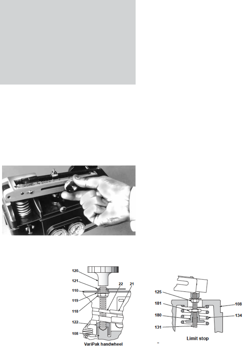
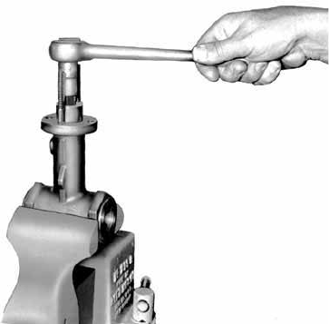
2.4 HANDWHEEL(Figure 5)
The handwheel is an optional feature located on top
of the cover and fitted with a locking lever. Access
can be gained to it directly without removing any
other parts. It consists of a threaded rod, equipped
with a handwheel (120) and a lever arm stop (122).
The threaded rod rests freely on the actuator bracket
(108) and is guided through the cover (110) by
handwheel bushing (119). The stop consists of a block
screwed onto the threaded rod. The block is guided
by the actuator bracket (108).
Figure 5

8 | GE Oil & Gas
When the handwheel (120) is turned clockwise, the
stop (122) moves up the threaded rod, compressing the
spring (134) and raising lever No. 2 (22) (VariPak 28002)
or (113) (VariPak 28001). This closes the valve if the valve
is equipped with a direct-action actuator (Air-to-Close)
and opens the valve if it is equipped with a reverse-
action actuator (Air-to- Open).
The valve can be returned to automatic mode (neutral
position), by turning the handwheel counterclockwise
until the stop (122) comes into contact with the bracket
(108).
Note: During this operation, the compression is released
when the stop (122) moves away from the lever (22)
(VariPak 28002) or (113) (VariPak 28001). Continue the
operation until a slight tension reappears, then tighten
the handwheel lock (121).
VariPak actuators are equipped with a limit stop. This
consists of parts (180) and (181), and is designed to
prevent damage to the plug and seat ring assembly
and/or the plug stem in the event of handwheel or
actuator overstroke.
Note: The limit stop is not used with air-to-open valves
fitted with a handwheel, and must be screwed down at
the bottom of the piston.
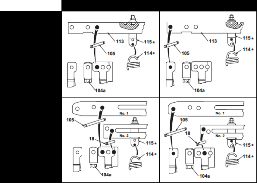
2.5 REVERSING THE VALVE ACTION
(Figures 5, 6, 26, 27 and 29)
Caution: The valve must be isolated and
pressure vented before disassembly.
A. Loosen and remove cover (110). On valves equipped
with a handwheel, loosen cover screw (109), back
off handwheel lock (121), and turn handwheel (120)
counter-clockwise to release cover (110).
B. Adjust the signal so that the valve closes. Change the
signal slightly so that the plug just moves off the seat
ring. On the VariPak 28002 adjustable-Cv valve, set
the adjustment knob (24) to the minimum Cv setting.
C. Loosen locknut (103) and, using a screwdriver,
turn the plug stem one and three-quarter turns
counter-clockwise. Shut off the signal and the supply
pressure. Slightly tighten locknut (103) against the
clevis.
D. Unlock nut (117) and completely loosen screw (116).
Unhook spring (114) from spring clamp (115).
2.5.1 VariPak 28001 single-lever valve
E. Remove retainer clips (112b) from pin (18), and remove
the pin from lever (113) and plug clevis (104a).
Note: This operation will be simplified by relieving
the load exerted on the plug clevis by the conical
compression spring (106). To do this push against the
plug stem end with a screwdriver while driving out the
pins.
F. Remove the two retainer clips (112a) from the pin (105)
and disengage it to uncouple the lever (113) from the
bracket (108).
G. Refit the levers (113) making sure that the pin (105) is
fitted into the correct holes in the lever and bracket
for the new action of the actuator (see figure 6). Fit
the spring clamp (115) into the corresponding lever
hole.
Note: Ensure that the clevis is correctly positioned before
fitting the lever on the bracket.
H. Couple the plug stem clevis (104a) to the lever (113)
following the normal reassembly procedure (step
I. in the "Reassembly" section on page 17). Then
follow the same procedure as for the VariPak 28002
adjustable-Cv valve as from step L.
2.5.2 VariPak 28002 adjustable-Cv valve (2 levers)
E. Remove retainer clips (112b) from each of the two
pins (184) and remove pins from lever (113) and plug
clevis (104a).
Note: This operation will be simplified by relieving
the load exerted on the plug clevis by the conical
compression spring (106). To do this push against the
plug stem end with a screwdriver while driving out the
pins.
F. Remove the two retainer clips (112a) from pin No. 1
(105) and disengage it to uncouple lever No. 1 from
bracket (108). Loosen adjustment knob (24) and slide
it to the maximum Cv setting. Disengage the smooth
end of the adjustment pin (23) from the groove in lever
No. 2 while removing lever No. 1.
G. Drive out pin No. 3 (18) and remove lever No. 2 (22)
from the bracket.
H. Remove the two screws (26) and refit Cv adjustment
plate (25) after turning it round to comply with the
new action.
I. Refit levers No. 1 and 2 in sequence, making sure that
pins (105) and (108) are fitted into the correct holes
in the levers and bracket for the new action of the
actuator (see figure 6).
Masoneilan VariPak Adjustable Cv Control Valves Instruction Manual | 9
Note: Ensure that the clevis is correctly positioned before
fitting the lever No. 1 on the bracket (108).
J. Reset adjustment knob (24) to the minimum Cv
position.
K. Couple plug stem clevis (104a) to lever No. 1 following
the normal reassembly procedure (step L. in the
"Reassembly" section on page 17).
L. Hook spring (114) in the appropriate hole in spring
clamp (115) (see figure 6).
M. Admit supply and signal pressures and complete
calibration. Refit cover (110) using the two screws
(109). If the valve is equipped with a handwheel, refit
the cover and turn the handwheel clockwise so that
it engages in lever arm stop (122). Tighten cover
screws (109).
N. Put the valve back into service.
Note:
- When replacing an Air-to-Close actuator with an Air-to-
Open actuator, do not forget to neutralize the limit stop
by screwing it down at the bottom of the piston.
- When replacing an Air-to-Open actuator with an
Air-to-Close actuator, set the limit stop to the opening
position.
AIR-TO-CLOSE ACTUATOR AIR-TO-OPEN ACTUATOR
VariPak 28001
with single lever
VariPak 28002
with adjustable
Cv (2 levers)
*Only with type 7700 positioner
Figure 6 - Identification of lever pivot pin holes

10 | GE Oil & Gas
3.1 Preliminary Steps
A. Before installing the valve in the line, remove all
traces of foreign material from the piping such as
welding chips, scale, oil, grease, etc.
B. Note down all the data given on the serial plate.
C. For valve inspection without interrupting process
operation, a hand-operated stop valve will be
required on either side of the VariPak, together with a
hand-operated throttling valve mounted on a bypass
line.
3.2 Valve Installation (Figures 7, 8 and 9)
Connections: The body of the ANSI Class 1500* rated
VariPak valve can be:
- Bolted between 25 mm (1") pipe flanges machined to
standards ISO-PN 10 to PN 250 (ANSI 150 - 300 - 600 -
900 and 1500 lb).
Use ASTM A 193 Gr B 7 (or equivalent) carbon steel
bolting for temperatures between -29° and +350 °C.
For corrosive or cryogenic service, use ASTM A 193 Gr
B8 strain-hardened stainless steel. All the line bolting
required for installation can be supplied by GE on
request.
Figure 7 - VariPak flanged connection
- Connected by 25 mm flanges machined to standards
ISO-PN 20, 50 and 100 (ANSI 150, 300 and 600 lb).
Fit gaskets compatible with service conditions between
the valve body and the pipe flanges.
Figure 8 - VariPak flanged body
The VariPak valve body can be supplied on request with
1/2", 3/4", or 1" NPT threaded ends. Apply PTFE tape or a
sealing compound compatible with the process to the
threaded pipe ends.
Figure 9 - VariPak screwed connection (option)
Alignment: This valve is small and light, making it easy
to install on the piping. Support the valve body when
fitting studs. Suitably shaped bosses are provided to
center the valve in the line and prevent rotation before
the studs are finally tightened.
The valve must always be installed with "flow tending
to open". The flow arrow on the valve body must be
pointing in the direction of flow. Fit the bolts and tighten
in criss-cross fashion.
3. Installation

Masoneilan VariPak Adjustable Cv Control Valves Instruction Manual | 11
Insulation: If the valve is to be insulated, ensure that the
insulation does not exceed the shaded area shown in
figure 10 below.
Figure 10 - Insulation limit for a VariPak valve
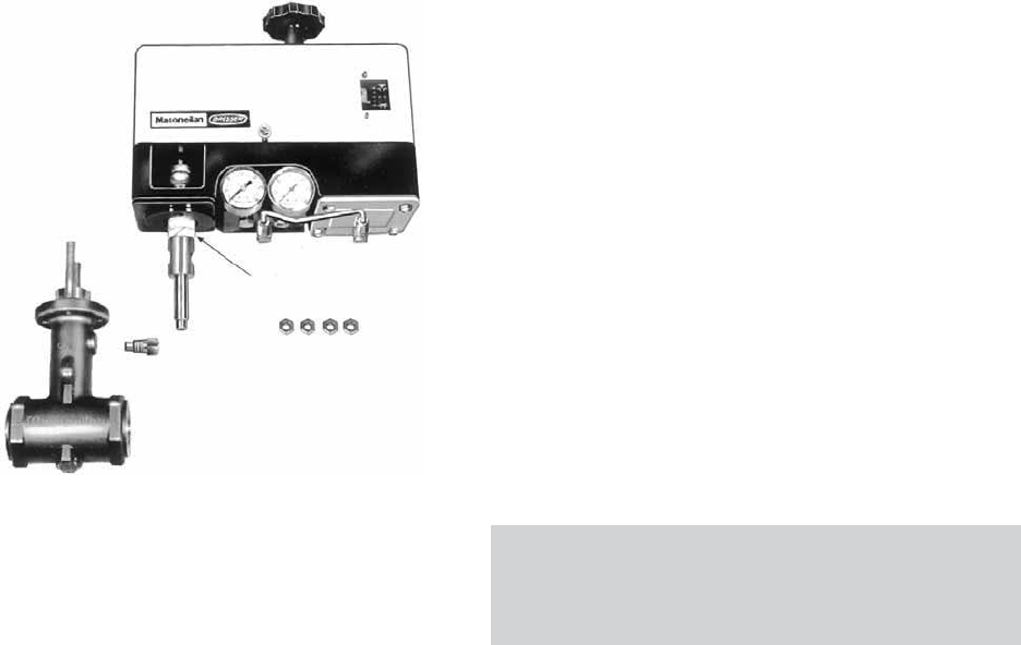
3.3 Pneumatic and Electrical Circuit
(Figures 3, 11 and 12)
- On-off valve: connect the air supply line directly to the
1/8" NPT threaded connection in diaphragm cover
(137).
- Control valve with 7700P positioner (air signal):
connect the supply and instrument signal lines to the
appropriate connections on the manifold block (144)
(figure 11). Use 4 x 6 mm (1/4" O.D.) tubing.
- Control valve with 7700E positioner (electrical signal):
connect the manifold block (144) air supply line and
make the electrical connection for the I/P module (20)
(figure 12).
Use 4 x 6 mm (1/4" O.D.) tubing for the air line.
Note: Check that the supply pressure is that indicated on
the serial plate.
7700P or 7700E positioners can be installed on
both VariPak 28001 single-lever and VariPak 28002
adjustable-Cv valves.
Figure 11 - Connections with 7700P positioner
Figure 12 - Connections with 7700E positioner
3.4 Limit Switches (Figure 13)
In some cases, limit switches can be provided for the
VariPak valve, on request. These are wired and adjusted
in the factory to customer order. The black wire is
connected to either the normally open or normally
closed terminal of the upper limit switch. The black and
white wire is connected to the common terminal of this
switch. The red wire is connected to either the normally
open or normally closed terminal of the lower limit
switch.
The red and white wire is connected to the common
terminal of this switch. To adjust limit switches, loosen
their fasteners and move the valve to the required
position. Adjust the position of the switch until it trips.
Tighten fasteners (160 - 161 - 162).
Figure 13 - Limit switch installation
12 | GE Oil & Gas
VariPak valves are factory-calibrated according to
the components specified in the customer order. If for
any reason this calibration has been disturbed (e.g.
after changing from direct to reverse valve action, or
replacing the plug and seat ring), all or some of the
adjustments below must be carried out in the following
order:
- Piston rod clevis (104b) adjustment.
- Plug stem adjustment.
- Limit stop adjustment.
- Cv adjustment.
- Positioner start-up pressure adjustment.
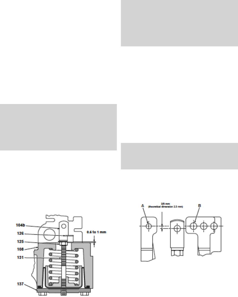
4.1 PISTON ROD CLEVIS ADJUSTMENT
4.1.1 Adjusting the piston rod clevis on the VariPak
28001 single-lever valve (Figures 14 and 26)
This adjustment is only required if the piston
(131) has been removed. In this case, it
should be carried out during reassembly,
before coupling the lever (113) to the clevises
(chap. MAINTENANCE - Reassembly. step H.,
page 17).
With the piston resting against diaphragm cover (137),
turn clevis (104b) so that the top of actuator bracket
(108) is 0.5 mm to 1 mm from the bottom of indicator
(126). A shim will simplify this operation. Admit enough
air pressure to disengage locknut (125) and tighten it
against indicator. Check that indicator (126) is correctly
positioned. Release air pressure.
4.1.2 Adjusting the piston rod clevis on the
Figure 14 - Piston rod clevis (104b) adjustment
VariPak 28002 adjustable-Cv valve (Figures 14 and 27)
This adjustment is only required if the piston
(131) has been removed.
In this case, it should be carried out during
reassembly, before coupling the levers (21)
and (22) to the clevises (chap. MAINTENANCE
- Reassembly. step K., page 17).
With the piston resting against diaphragm cover (137),
turn clevis (104b) so that the top of the actuator bracket
(108) is 0.5 mm to 1 mm from the bottom of indicator
(126). A shim will simplify this operation.
Couple lever No. 2 (22) in this clevis position. Admit
enough air pressure to disengage locknut (125) and
tighten it against the indicator. Check that indicator
(126) is correctly positioned. Release air pressure.
4.2 PLUG STEM ADJUSTMENT
4.2.1 Adjusting the plug stem on the VariPak 28001
single-lever valve (Figures 15, 16 and 26)
This adjustment should be carried out during
reassembly, before coupling the lever (113) to
the clevises.
A. Loosen nut (103) and turn the plug stem using a
screwdriver while blocking clevis (104a) until the clevis is
in the position shown in figure 15. Lock nut (103).
Figure 15 - Presetting the plug stem position
4. Calibration
Masoneilan VariPak Adjustable Cv Control Valves Instruction Manual | 13
B. Fit lever (113) with spring clamp (115) positioning hole
facing upwards, fit pin (105) into hole A, then fit pin
(18) into clevis (104a). Note: All pins should be greased
slightly before fitting.
C. Press the lever on the actuator side to check for plug/
seat ring leaks at ΔP 3.5 barg (50 psig). If the valve is
equipped with a handwheel, lever (113) should not
touch lever arm stop (122). If the valve leaks, release
the pressure at the inlet and remove pin (18) of clevis
(104a), then loosen nut (103). Loosen the plug stem in
order to move the clevis up (104a). A complete turn
moves the position up by 1 mm. Then tighten the
locknut (103) again.
D. Check that the distance between clevis (104b) pin
and the hole in lever (113) is approximately 2 mm.
If necessary, adjust the position of clevis (104a) to
obtain this distance, see figure 16. This value provides
the initial compression of actuator spring (134).
Figure 16 - Adjusting the lever (113)
E. Admit enough air pressure to the actuator to drive
piston clevis (104b) upwards. Couple the clevis to
lever (113) using pin (124).
F. Release the actuator pressure and repeat the plug/
seat ring leak test at ΔP 3.5 barg (50 psig). Dimension
A should be the same as in figure 16 . Release the
valve pressure once this step is completed.
4.2.2 Adjusting the plug stem on the VariPak 28002
adjustable-Cv valve (Figures 27, 28 and 29)
Once all the coupling operations are completed,
proceed as follows:
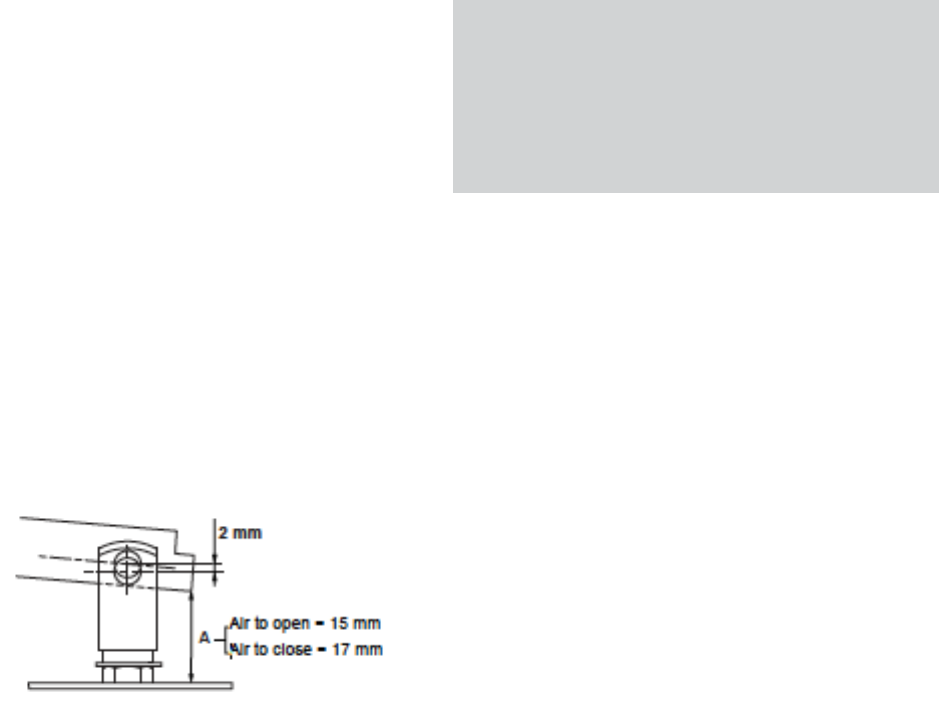
A. Admit enough pressure to the actuator to drive out
the piston rod far enough to place a shim under
the indicator (126). Use a 1.5 mm shim for an Air-to-
Open actuator, and a 25 mm shim for an Air-to-Close
actuator. Release the air pressure after inserting the
shim.
At this closing point where the plug is not
tightened onto the seating, the slides of
levers No. 1 and 2 should be perfectly
parallel. This characteristic makes it possible
to change the adjustment knob (24) position
later to obtain the required real Cv value.
B. Loosen adjustment knob (24) and slide it along lever
No. 1 to the maximum Cv position on adjustment
plate (25). Fully tighten adjustment knob (24).
C. Loosen locknut (103) and, using a screwdriver, turn
the plug stem until the plug is just touching the seat
ring. If the valve has been removed from the pipe,
a bubble test can be performed on the calibration
bench to obtain a very accurate adjustment. Using
the screwdriver to hold the plug stem in position,
tighten locknut (103) against clevis (104a).
D. Admit air pressure again to remove the shim, then
release the pressure.
Note: On an Air-to-Open actuator, shim thickness may
be increased or decreased by one or two-tenths of a
millimeter to ensure that levers No. 1 and 2 are perfectly
parallel and to obtain the required tightness on closing,
especially for very low Cv values (Cv < 0.10).
4.3 LIMIT STOP ADJUSTMENT (Figure 5)
VariPak valves include a limit stop to prevent damage to
the plug and seat ring and/or plug stem in the event of
actuator or handwheel overstroke. This device consists
of a nut (180) acting as a stop, screwed onto the piston
rod inside the spring chamber, and a locknut (181).
If necessary, this device should be adjusted
immediately after plug stem adustment (see section
4.2).
A. Remove the shim (for VariPak 28002 adjustable- Cv
valve only) and admit sufficient supply pressure to
close the valve. Turn locknut (181) on the piston rod
until it touches locknut (125). Turn limit stop (180) until
it just touches the inside of actuator bracket (108).
B. Hold the limit stop with a 12 mm wrench and tighten
locknut (181). Release the air pressure.

14 | GE Oil & Gas
4.4 VARIPAK 28002 Cv ADJUSTMENT
This adjustment is carried out by moving adjustment
knob (24) along adjustment plate (25) fastened to the
top of lever No. 1 (21). See section “Adjusting the Cv
of a Varipak 28002 valve for each plug and seat ring
combination”, page 7.
4.5 POSITIONER START-UP PRESSURE ADJUSTMENT
(Figures 7, 25, 26 and 27)
A. Connect the air supply and signal lines to the 7700P
or 7700E (with electrical signal) positioner.
B. Set the supply pressure according to the valve Cv
value (see the table in figure 3).
C. Set the signal to the minimum value for an Air-to-
Open actuator, and to the maximum value for an Air-
to-Close actuator. Turn take-up screw (116) until the
piston rod just begins to move. Tighten locknut (117).
5. Maintenance
Caution: Always ensure that there is no
pressure in the valve, actuator, or positioner
before maintenance or disassembly.
5.1 ACTUATOR DIAPHRAGM REMOVAL
(Figures 17, 24, 25, 26 and 27)
A. Unscrew the two pressure connection nuts (138a)
and pull tubing (140) out. Remove the four cap screws
(139) and diaphragm cover (137). Remove the worn
diaphragm. Form new diaphragm (136) and fit it on
the piston as shown in figure 17. Fit the diaphragm
roll into the bracket groove. Take care not to twist
or bend the diaphragm during replacement. Refit
diaphragm cover (137) with the four screws (139)
and reconnect the tubing with the two pressure
connection nuts (138a). Check that all connections
are leaktight.
Figure 17 - Diaphragm replacement
5.2 ADDING PACKING RING (Figures 18, 26 and 27)
A. Before adding packing ring, the valve must be
isolated and all pressure released. Remove packing
flange nuts (8b), lift the packing flange and follower,
and insert a new packing ring. Tighten nuts (8b)
finger tight and then tighten one full turn with the
wrench.
Figure 18 - Adding a packing ring

Masoneilan VariPak Adjustable Cv Control Valves Instruction Manual | 15
5.3 DISASSEMBLY (Figures 5, 24, 25, 26, 27, 28 and 29)
In some cases, it may be necessary to disassemble the
VariPak valve, for example, to replace the plug/seat ring
assembly (fitting new parts or changing the maximum
Cv value) or to change the packing rings when the
maximum Cv is less than 0.6.
Note: If the maximum Cv ≥ 0.6, a quick change method
can be used to avoid disassembling the valve (see page
18).
Caution: The valve must be isolated and
pressure vented before disassembly.
A. Loosen cover screws (109) and remove cover (110). If
the valve is equipped with a handwheel, loosen cover
screws (109) and handwheel lock (121), then turn
handwheel (120) counterclockwise to release cover
(110).
Disassembly procedure for the VariPak 28001 single-
lever valve:
B. Unlock nut (117) and completely loosen screw (116).
Remove spring clamp (115) from lever (113) and
remove spring (114) from the positioner.
C. Remove the two retainer clips (112c) from pin (124)
and disengage the pin to uncouple piston clevis
(104b) from lever (113).
Note: To simplify this operation, admit air pressure to the
actuator to drive the piston clevis (104b) upwards, then
release the air pressure.
D. Remove retainer clips (112b) from pin (18) and
disengage the pin from lever (113) and plug clevis
(104a).
E. Remove two retainer clips (112a) from pin (105)
and disengage the pin to uncouple lever (113) from
actuator bracket (108). Now proceed in the same way
as for the VariPak 28002 adjustable- Cv valve, as from
step I.
Disassembly procedure for the VariPak 28002
adjustable-Cv valve:
B. Adjust the signal to close the valve. Change the signal
slightly so that the plug just moves off the seat ring.
Set adjustment knob (24) to the minimum Cv position.
C. Loosen locknut (103) and, using a screwdriver, turn
the plug stem one and three-quarter turns counter-
clockwise. Shut off signal and supply pressure.
Slightly tighten locknut (103) against the clevis.
D. Completely loosen locknut (117) and screw (116).
Remove spring clamp (115) from lever No. 2 and
remove balance spring (114) from the positioner.
E. Remove the retainer clip (112b) from each of the two
pins (184) and disengage the pins from lever No. 1
and clevis (104a).
Note: This operation will be simplified by relieving
the load exerted on the plug clevis by the conical
compression spring (106). To do this push against the
plug stem end with a screwdriver while driving out the
pins.
F. Remove the two retainer clips (112c) from pivot pin
No. 4 (124) and disengage the pin to uncouple piston
clevis (104b) from lever No. 2 (22).
G. Remove the two retainer clips (112a) from pivot pin
No. 1 (105) and disengage the pin to uncouple lever
No. 1 from the actuator bracket (108). Disengage the
smooth end of adjustment pin (23) from the groove
in lever No. 2 and remove adjustment knob (24) and
adjustment pin (23) from lever No. 1.
H. Drive out pivot pin No. 3 (18) and remove lever No. 2
(22).
I. Hold the plug stem in place using a screwdriver and
unlock nut (103). Loosen clevis (104a) and locknut (103).
Remove spring button (102), spring (106), and grommet
plate (101).
J. Remove the two packing flange nuts (8b), packing
flange (10) and packing follower (9). Remove the two
bracket mounting nuts (8a) as well as the bracket
(108).
K. Using a packing hook, remove as many packing rings
(6) as possible from the packing box. Remove safety
pin (11) and pull the plug stem to remove the packing
spacer (5), the plug and its stem and, if necessary, the
rest of the packing.
L. Using a 9/16" or 14 mm piece of hex stock and a
wrench, unlock and pull out the seat-ring retainer (4).
M. Remove seat ring (3) and gasket (2) using a hook
made from steel wire, approx. diameter 3 mm.
Carefully fettle the hook end.
Note:
- The seat-ring of VariPak valves with Cv max.< 0.10
consists of two parts: the seat ring proper (3e), and
a spacer (3f). These parts have a small orifice and
so cannot be removed using a hook. It is therefore
necessary to remove the body from the pipe and turn
it over and, if necessary, hit the bottom with a wooden
mallet. If the seat ring (3a) is jammed in its housing, it
can be removed by inserting a screwdriver through the
outlet orifice.
16 | GE Oil & Gas
- VariPak valves with Cv max. 3.8 do not have seatring
gaskets (2).
5.4 REASSEMBLY (Figures 5, 15, 19, 20, 24, 25, 26, 27,
28 and 29)
Before reassembly, thoroughly clean the inside of the
valve body and parts, paying particular attention to
gasket seating surfaces and contact surfaces. Make
sure to use a new seat-ring gasket (2) and new packing
(6) during reassembly.
A. Insert a new seat-ring gasket (2) into valve body (13),
then fit seat ring (3), making sure that the gasket is
correctly centered on the seat-ring shoulder. Turn it
so that one of its ports is lined up with the valve body
outlet orifice.
Note: If the maximum Cv is less than 0.10, first fit the
seat ring (3e) on the new gasket (2), taking the same
precautions as above. Then fit the spacer (3f), turning it
so that one of its ports is turned towards the body outlet
orifice.
VariPak valves with a maximum Cv of 3.8 do not include
a seat-ring gasket (2).
B. Carefully apply Never Seez grease or equivalent to
the threads and bottom of the seat-ring retainer
(4). Using a 9/16" or 14 mm piece of hex stock and a
wrench, torque the retainer to 59 ftlb or 8 daN.m for
stainless-steel reinforced graphite gaskets or 40 ft-lb
or 5.5 daN.m for glass-filled PTFE gaskets (see figure
19).
Note: Torque the retainer to 30 ft-lb or 4 daN.m for
valves with a maximum Cv of 3.8.
C. Insert the plug and stem assembly into the seat
ring. For valves with a maximum Cv < 0.10, check
that there are no friction points in the plug stroke.
If a friction point is detected, loosen retainer (4)
and reposition seat ring (3e) until the stem slides
smoothly. Fit spacer (5), turning it so that one of its
holes is aligned with safety pin (11) hole in the valve
body.
Note: For valves with a maximum Cv less than 0.10,
check that the retaining ring (182) is fitted on the plug
before fitting the plug in the spacer (3f). If the retaining
ring is worn or damaged, replace it.
Figure 19 - Tightening the seat-ring retainer (4)
D. Wind two layers of PTFE tape around the safety pin
(11). Screw the pin into the bonnet five and a half to
six turns as from the thread engagement point.
Note: To determine the thread engagement point:
- Screw the safety pin about one turn.
- Pull the safety pin out while unscrewing it.
E. Fit the packing, making sure that the skive cut of
each packing ring is located 120° away from the that
of the adjacent ring. Push the rings down slightly
using a 1/2" sch., size 160 tube. Fit the packing
follower (9) onto the plug stem.
F. Fit actuator bracket (108) and secure it with two
nuts (8a). Slip packing flange (10) onto plug stem.
Handtighten the two packing flange nuts and add
one full turn with the wrench.
G. Fit, in the following order, grommet plate (101),
conical compression spring (106) and its spring
button (102) (see position in figure 26 and 27). Screw
nut (103) and clevis (104a) on the plug stem.
Adjust the nut and clevis without locking them together
until the clevis holes are positioned approximately:
- 2.3 mm below the alignment of the pin holes in
the actuator bracket (108) for the VariPak 28001
single-lever valve (see figure 15).
- 1.5 mm above the alignment of the pin holes in
the actuator bracket (108) for the VariPak 28002
adjustable-Cv valve (see figure 20).
Note: Measuring this distance can be simplified by fitting
pins (105), (184) and (18) into their holes.

Masoneilan VariPak Adjustable Cv Control Valves Instruction Manual | 17
Figure 20 - Plug stem pre-adjustment for
VariPak 28002 adjustable-Cv
Reassembly procedure for the VariPak 28001 single-
lever valve (continued):
H. Couple lever (113) to actuator bracket (108) using pin
(105) and the 2 retainer clips (112a). Ensure that the
holes in lever (113) where spring clamp (115) is fitted
is located above.
Note: Check that the clevis (104a) is correctly positioned
before fitting the lever (113) on the actuator support
(108).
To identify the position of the lever connecting holes and
the spring clamp (115) attachment hole, with respect to
the required action, see figure 6.
I. Couple clevis (104a) to lever (113). To do this, press the
end of the plug stem with a screwdriver until the holes
in the clevis and lever are aligned. Couple using the
pin (18) and retainer clips (112b).
Note: Slightly grease all pins before fitting. Perform the
adjustment operation described in "Calibration", section
4.2.1, page 12.
J. If piston rod clevis (104b) has not been disturbed
during disassembly, couple it to the end of lever (113)
by admitting air pressure to the actuator to drive
clevis (104b) upwards. Couple the clevis to lever (113)
using pin (124) and two retainer clips (112c).
Note: If the clevis (104b) has been disturbed, proceed
with adjustment and coupling as described in
"Calibration", section 4.1.1, page 12.
K. Release the pressure from the actuator and check
tightness again (see "Calibration", section 4.2.1, page
12). Then continue from step M. of the VariPak 28002
procedure.
Reassembly procedure for the VariPak 28002
adjustable-Cv valve (continued):
H. Couple lever No. 2 (22) to the actuator bracket (108)
using pin (18). Ensure that the hole in lever No. 2
where spring clamp (115) is fitted is located above
and in line with balance spring (114).
I. Fit adjustment pin (23) in the slide of lever No. 1 and
screw adjustment knob (24) on its threaded end. Insert
the smooth end of pin (23) into the groove in lever
No. 2 and place lever No. 1 on support bracket (108).
Couple lever No. 1 to actuator bracket (108) using pin
(105) and two retainer clips (112a).
Note: Check that the clevis (104a) is correctly positioned
before fitting lever No. 1 on the actuator support (108)
To identify the position of the connecting holes of levers
No. 1 and 2 with respect to the required action, see
figure 6.
J. Set adjustment knob (24) to the minimum Cv position.
K. If piston rod clevis (104b) has not been disturbed
during disassembly, couple it to the end of lever No. 2
using pin (124) and two retainer clips (112c).
Note: This operation will be simplified by applying air
pressure to the diaphragm (136) to set the piston rod to
an intermediate position, and by setting the adjustment
knob to a position where lever No. 2 is most accessible.
If the clevis (104b) has been disturbed, proceed with
adjustment and coupling as described in "Calibration",
section 4.1.1, page 12.
L. Couple clevis (104a) to lever No. 1. To do this, press
the end of the plug stem with a screwdriver until the
holes in the clevis and lever No. 1 are aligned. Couple
using the two pins (184) and retainer clips (112b).
Note: The clips are inserted on the pins between the
sides of the clevis and lever No. 1.
M. Fully unscrew take-up screw (116) from spring clamp
(115), then fit clamp, after hooking balance spring
(114) first to the positioner spring bracket of the
diaphragm S/A (152), and then to spring clamp (115).
Note: The spring clamp (115) has two holes. If an Air-to-
Open actuator is used, the spring must be hooked to the
top hole. If an Air-to-Close actuator is used, the spring
must be hooked to the bottom hole (see figure 6).
18 | GE Oil & Gas
N. Admit the signal and supply pressure and complete
calibration. Refit cover (110) using the two screws
(109). If the valve is equipped with a handwheel, refit
the cover, then turn the handwheel clockwise until
it is engaged in lever arm stop (122). Tighten cover
screws (109).
O. If the valve body has been removed, reinstall it taking
the precautions given under "Valve Installation" on
page 10. Put the valve back into service.
5.5 PACKING QUICK CHANGE METHOD (ONLY FOR
VALVES WITH MAX. Cv OF 0.6 TO 3.8)
(Figures 21, 26 and 27)
The quickest and easiest way to replace packing is
to remove the entire actuator from the valve body,
taking care not to modify the actuator setting. This
method is not recommended, however, for valves with
a maximum Cv less than 0.6 because of their extremely
fine plugs. For these valves, disassemble the valve to
replace the packing (see "DISASSEMBLY", page 15).
Figure 21 - Packing replacement (for Cv maxi ≥ 0.6)
Vent the valve pressure and proceed as follows:
A. Check that the plug is not resting on the seat ring.
For valves equipped with an Air-to-Open actuator,
admit air pressure under the diaphragm and turn the
handwheel to move the plug off its seat ring.
B Remove safety pin (11) from the valve body. The
safety pin stub engages with the hole in packing
spacer (5). The function of the safety pin and spacer
is to prevent the plug from being pushed out if the
actuator is accidentally removed while the valve is
still pressurized. The internal parts of the valve cannot
be removed unless the safety pin is removed first.
Remove the two packing flange nuts (8b) and back off
the two actuator bracket mounting nuts (8a) as far as
possible.
C. Remove the actuator-plug assembly from the valve
body, tapping it off with a block of wood and mallet if
necessary. Clean the packing box in the valve body.
Remove the worn packing, then clean the plug stem
thoroughly. Carefully fit new packing rings around
the stem, positioning the skive cut of each ring 120°
from that of the adjacent ring.
D. Refit the actuator-plug assembly on the valve body,
taking care to: - align hole in packing spacer (5) with
safety pin (11) hole,
- and refit the two mounting nuts (8a).
- Take extra care when guiding each packing ring
into the packing box.
E. Wind two layers of PTFE tape around the safety pin.
Screw the pin into the bonnet five and a half to six
turns as from the thread engagement point.
Note: To determine the thread engagement point:
- Screw the safety pin about one turn,
- Pull the safety pin out while unscrewing it.
F. Refit the packing follower, packing flange, and flange
nuts (8b). Tighten the packing assembly correctly. If
the valve is equipped with an Air-to- Open actuator,
release the air pressure or turn the handwheel to
bring the plug back into contact with the seat ring.
Put back into service.
5.6 7700P OR 7700E POSITIONER MAINTENANCE
(Figures 22, 23, 24, 25, 26 and 27)
Caution: Shut off the signal and supply
pressure. Isolate and depressurize the valve
body.
A. Disconnect the two pressure connection nuts (138a)
and pull tubing (140) out.
Masoneilan VariPak Adjustable Cv Control Valves Instruction Manual | 19
B. Loosen the two cap screws (141a) and remove
manifold block (144), spring (158), gasket (146) and its
three O-rings, pilot valve assembly (155 to 157), shims
(145), and O-ring (153).
Caution: Handle the shims carefully (145).
C. Loosen locknut (117) and take-up screw (116), unhook
the spring clamp from lever (22) or (113).
D. Unscrew cap screws (141b) from positioner block (147)
and remove the positioner block from the actuator
bracket.
Remove screws (148) to separate positioner diaphragm
assembly (152) and spring (154) from the positioner
block. Examine all the parts and replace if worn or
damaged.
E. Refit positioner diaphragm assembly (152) and spring
(154) to positioner block and tighten screws (148).
Check that the small signal port Oring is in its recess
in the diaphragm assembly.
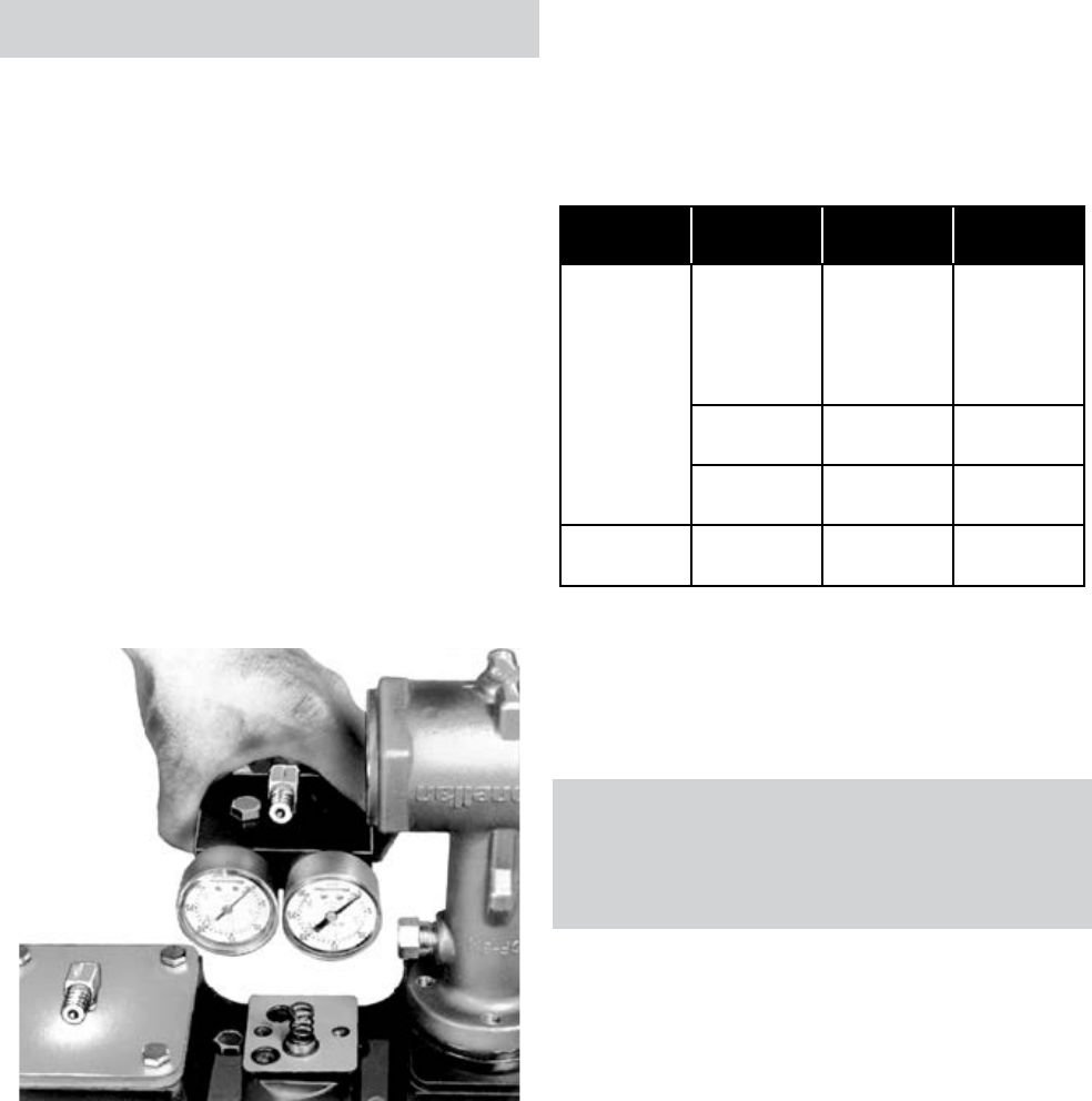
F. Reinstall the block assembly on the actuator bracket.
Note: When installing the positioner block (147), turn it
so that when the manifold block (144) is installed, the
gauge(s) is(are) facing in the right direction (figure 22).
Figure 22 - Positioner assembly
Note how the positioner (147) and gasket (146) are oriented
G. Check that gasket (146), three O-rings, and seats are
not worn or damaged and replace if necessary.
H. Fit O-ring (153), shims (145), pilot valve assembly,
gasket (146) and its three O-rings, spring (158) and
manifold block (144). Tighten the screws (141a), refit
tubing (140) and tighten pressure connection nuts
(138a).
Note: The ports in gasket (146) must be aligned with
those in the positioner block (147).
To ensure correct positioner performance, check that all
gaskets are perfectly leaktight.
I. Hook spring clamp (115) to lever (22) or (113). In the
case of VariPack 28001 valve, see figure 6 to position
the spring clamp (115) according to the actuator
required action. Admit the supply pressure and
the signal. Set the start-up pressure following the
instructions given in the "Calibration" chapter. Put
back into service.
Positioner Signal (Psi) Spring ref.
No.
Spring color
code
7700P
3-15
or
6-30
or
3-27
114
154
Yellow
Red
3-9 114
154
White
Blue
9-15 114
154
White
Green
7700E 4-20 mA 114
154
Yellow
Red
Figure 23 - Color code for positioner springs
(114 and 154)
5.7 MAINTENANCE OPERATIONS SPECIFIC TO THE
7700E POSITIONER
REFER TO ATEX INSTRUCTION MANUAL
No. 185977 FOR ALL MAINTENANCE ON
THE ELECTRICAL PARTS OF THE 7700E
POSITIONER.
A. Loosen screws (27) and remove I/P module (20).
Note: If damaged, the I/P module must be replaced.
B. Check that O-rings (28, 29 and 30) and their seats are
not worn or damaged.
Note: All worn or damaged parts must be replaced.
C. Fit O-rings (28, 29 and 30) in their recesses on the I/P
module (20). Refit I/P module (20) on manifold block
(144). Tighten screws (27).
Note: To ensure correct positioner performance, check
that all gaskets are perfectly leaktight.

20 | GE Oil & Gas
5.8 CONVERTING A 7700P POSITIONER (PNEUMATIC)
INTO A 7700E POSITIONER (ELECTROPNEUMATIC)
A kit comprising the manifold block (144) and the I/P
module (20) is available from your local Masoneilan
representative or the Spare Parts Department.
REFER TO ATEX INSTRUCTION MANUAL
No. 185977 FOR ALL MAINTENANCE ON
THE ELECTRICAL PARTS OF THE 7700E
POSITIONER.
Shut off the signal and supply pressure. Isolate and
depressurize the valve body.
A. Disconnect the two pressure connection nuts (138a)
and pull the tubing (140) out.
B. Loosen the two cap screws (141a) and remove
manifold block (144). The spring (158), gasket (146)
and the three O-rings, the pilot valve assembly (155
to 157), shims (145), and O-ring (153) do not need to
be removed unless you have new parts. Otherwise,
simply check that parts are in perfect condition
before refitting.
Caution: Handle the shims carefully (145).
C. If the parts mentioned above have been removed,
proceed as follows:
Fit the O-ring (153), shims (145), pilot valve assembly (155
to 157), gasket (146) and the three O-rings, the spring
(158) and manifold block (144) - I/P module (20). Tighten
screws (141a), refit tubing (140) and tighten pressure
connection nuts (138a).
Note: The ports in gasket (146) must be aligned with
those in positioner block (147).
To ensure correct positioner performance, check that all
gaskets are perfectly leaktight.
D. Hook spring clamp (115) to lever (22) (VariPak 28002)
or (113) (VariPak 28001). In the case of VariPack
28001 valve, see figure 6 to position the spring clamp
(115) according to the actuator required action.
Admit the supply pressure and enable the electrical
signal. Adjust the start-up pressure following the
instructions under "Calibration". Put back into service.
Masoneilan VariPak Adjustable Cv Control Valves Instruction Manual | 21
Ref. Qty Part Name Ref. Qty Part Name Ref. Qty Part Name
Δ ☐ 111/4" NPT pipe plug 101 1Grommet support plate 140 1Tubing
Ο 21Seat-ring gasket 102 1Spring button 141 (a, b) 4Screw
a1Seat ring Cv max. 3.8 103 1Locknut 142 1Output gauge
b1Seat ring Cv max. 2.3 and 1.2 104 2Clevis 143 1Instrument gauge
3 c1 Seat ring Cv max. 0.25 and
0.60 105 1 Pivot pin No. 1 144 1Manifold block
d1Seat ring Cv max. 0.10 106 1Conical compression spring 145 1 to 5 Shim
☐ e1Seat ring Cv max. < 0.10 Ο 107 1Grommet Ο 146 1 Gasket (includes 171 & 172)
☐ 3 f1Spacer Cv max. < 0.10 108 1Actuator bracket 147 1Positioner block
41Seat-ring retainer 109 2Cover screw 148 2 Slotted flat. c screw
51Packing spacer 110 1Cover Ο 152 1Positioner diaphragm S/A
Ο 61Packing ring 112 (a, b, c) 6Retainer clip Ο 153 1O-ring
72Packing flange stud 114 1Balance spring ♥ 154 1Spring
8 a2Mounting nut 115 1Spring clamp Ο 155 1Sleeve
8 b2Packing flange nut 116 1Take-up screw Ο 156 1Spool
91Packing follower 117 1Locknut Ο 157 1Spring
10 1Packing flange 118 1Handwheel locknut 158 1Spring
11 1Safety pin 119 1Handwheel bushing Δ 159 2Switch
12
a1Plug/stem Cv max. 3.8 120 1Handwheel Δ 160 4Screw
b1Plug/stem Cv max. 2.3 121 1Handwheel lock Δ 161 4Washer
c1Plug/stem Cv max. 1.2 & 0.6 122 1 Lever arm stop Δ 162 4Nut
d1Plug/stemCv max. 0.25 & 0.10 123 1Cover plug Δ 163 4Wire
13 a1Body Cv max. < 3.8 124 1 Pivot pin No. 4 Δ 164 1Terminal
13 b1Body Cv max. 3.8 125 1Locknut ■ 165 2Logo
18 1Pivot pin No. 3 (22/108) 126 1Indicator 168 1Cover washer
20 1I/P module 127 1Indicator plate 170 2Signal decal
21 1Lever No. 1 129 2Indicator plate screw ■ 171 1O-ring
22 1Lever No. 2 130 2Speed nut ■ 172 1O-ring
23 1Adjustment pin 131 1Piston S/A 173 1Cover plug
24 1Cv adjustment knob 133 2 Serial plate screw ▼ 180 1Limit stop
25 1Cv adjustment plate 134 1Actuator spring ▼ 181 1Locknut
26 2Adjustment plate screw 135 1Serial plate 182 1Retaining ring (Cv max. <0.10)
27 4Screw Ο 136 1Diaphragm 183 1Plug (Cv max. <0.10)
Ο 28 1O-ring 137 1Diaphragm cover 184 2 Pivot pin No. 2
Ο 29 1O-ring 138 1 Union elbow t(incl. 138a)
Ο 30 1O-ring 139 1 Cover cap screw
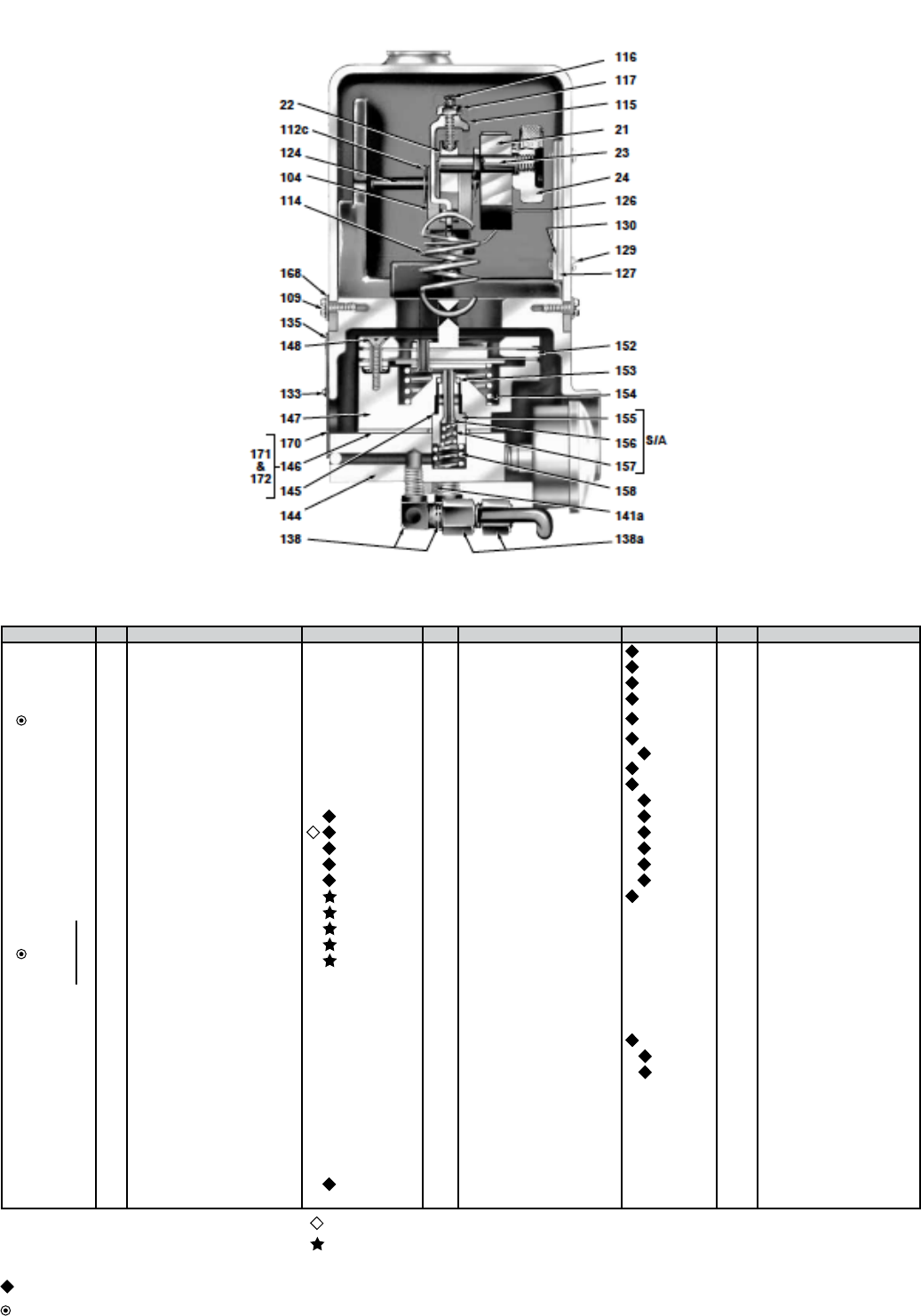
Figure 24 - Cross-section of the VariPak 28002 adjustable-Cv actuator and the 7700P positioner
PARTS LIST
Ο Recommended spare parts
☐ Complete subassembly includes: plug and stem (183),
retaining ring (182), seat ring (3e) and spacer (3f) (see
figure 2).
Only for pneumatic positioner.
See Figure 2.
See table in figure 23.
Only for handwheel (optional) (fig. 5).
Ο Complete subassembly includes Ref. Nos. (155, 156
and157).
■ Not shown.
▲ Only for cast bodies.
▼ Only on actuator with handwheel and/or Model 8013
E.P. positioner (fig. 5).
Δ Only for optional limit-switch adaptation: quantity
given for two limit switches (see fig. 13).

22 | GE Oil & Gas
180
181
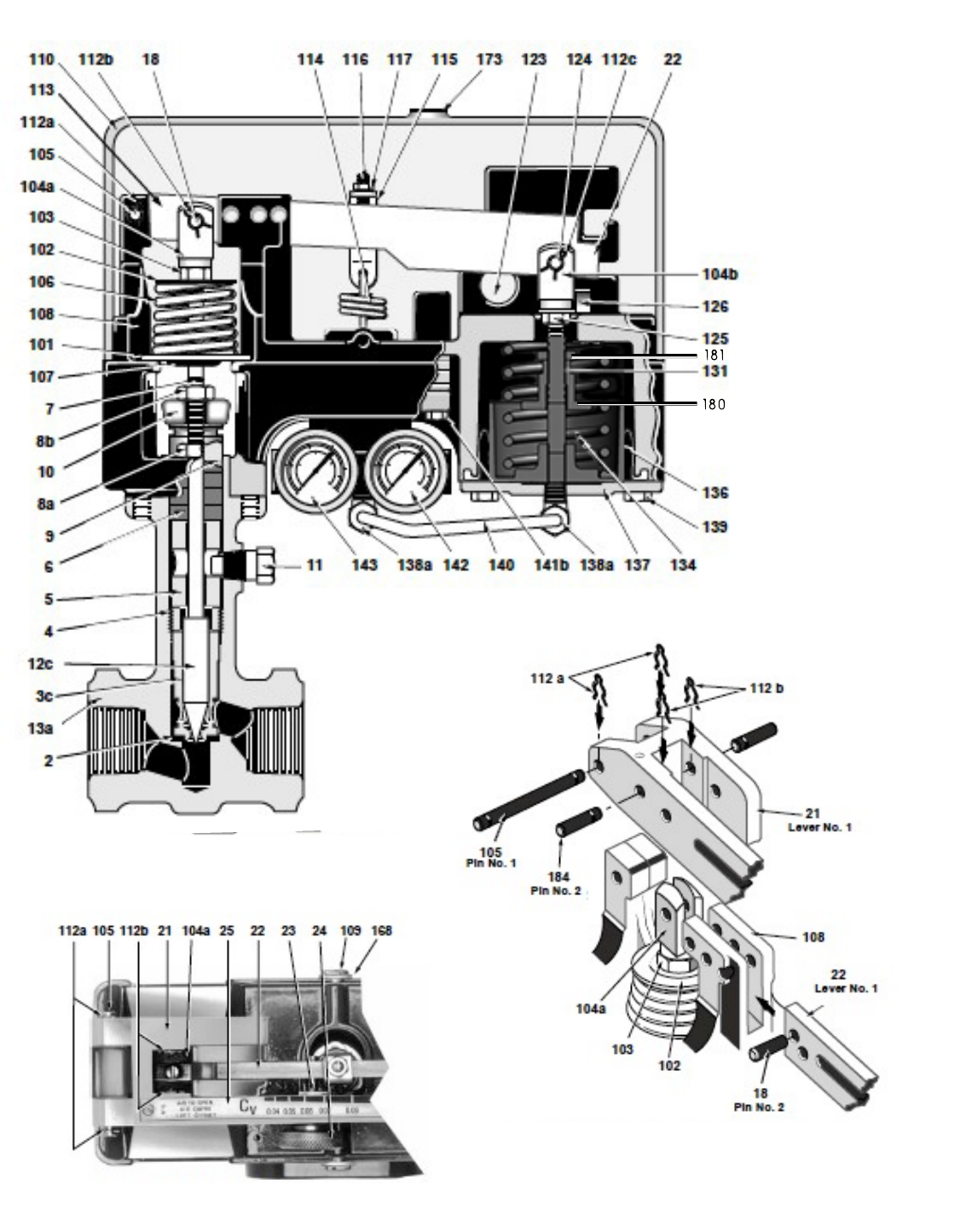
Figure 25 - Cross-section of the VariPak 28001
single-lever actuator and the
7700E positioner
Figure 26 - Partial cross-section of VariPak
28001 single-lever, air-to-open
valve
Masoneilan VariPak Adjustable Cv Control Valves Instruction Manual | 23
24 | GE Oil & Gas
Figure 27 - Partial cross-section of VariPak 28002
adjustable-Cv, air-to-open valve
Figure 29 - Coupling detail of levers No. 1 and 2
Figure 28 - Partial top view
180
181

180
181
GEA30857 03/2014
© 2014 General Electric Company. All rights reserved.
* Masoneilan and VariPak are registered trademarks of the General Electric Company.
Other company names and product names used in this document are the registered trademarks
or trademarks of their respective owners.
AUSTRALIA
Brisbane:
Phone: +61-7-3001-4319
Fax: +61-7-3001-4399
Perth:
Phone: +61-8-6595-7018
Fax: +61 8 6595-7299
Melbourne:
Phone: +61-3-8807-6002
Fax : +61-3-8807-6577
BELGIUM
Phone: +32-2-344-0970
Fax: +32-2-344-1123
BRAZIL
Phone: +55-11-2146-3600
Fax: +55-11-2146-3610
CHINA
Phone: +86-10-8486-4515
Fax: +86-10-8486-5305
FRANCE
Courbevoie
Phone: +33-1-4904-9000
Fax: +33-1-4904-9010
GERMANY
Ratingen
Phone: +49-2102-108-0
Fax: +49-2102-108-111
INDIA
Mumbai
Phone: +91-22-8354790
Fax: +91-22-8354791
New Delhi
Phone: +91-11-2-6164175
Fax: +91-11-5-1659635
ITALY
Phone: +39-081-7892-111
Fax: +39-081-7892-208
JAPAN
Chiba
Phone: +81-43-297-9222
Fax: +81-43-299-1115
KOREA
Phone: +82-2-2274-0748
Fax: +82-2-2274-0794
MALAYSIA
Phone: +60-3-2161-0322
Fax: +60-3-2163-6312
MEXICO
Phone: +52-5-310-9863
Fax: +52-5-310-5584
THE NETHERLANDS
Phone: +0031-15-3808666
Fax: +0031-18-1641438
RUSSIA
Veliky Novgorod
Phone: +7-8162-55-7898
Fax: +7-8162-55-7921
Moscow
Phone: +7 495-585-1276
Fax: +7 495-585-1279
SAUDI ARABIA
Phone: +966-3-341-0278
Fax: +966-3-341-7624
SINGAPORE
Phone: +65-6861-6100
Fax: +65-6861-7172
SOUTH AFRICA
Phone: +27-11-452-1550
Fax: +27-11-452-6542
SOUTH & CENTRAL
AMERICA AND THE CARIBBEAN
Phone: +55-12-2134-1201
Fax: +55-12-2134-1238
SPAIN
Phone: +34-93-652-6430
Fax: +34-93-652-6444
UNITED ARAB EMIRATES
Phone: +971-4-8991-777
Fax: +971-4-8991-778
UNITED KINGDOM
Wooburn Green
Phone: +44-1628-536300
Fax: +44-1628-536319
UNITED STATES
Massachusetts
Phone: +1-508-586-4600
Fax: +1-508-427-8971
Corpus Christi, Texas
Phone: +1-361-881-8182
Fax: +1-361-881-8246
Deer Park, Texas
Phone: +1-281-884-1000
Fax: +1-281-884-1010
Houston, Texas
Phone: +1-281-671-1640
Fax: +1-281-671-1735
DIRECT SALES OFFICE LOCATIONS
