GemTek Technology A901023 Wireless LAN Access Point User Manual WX 1590 manual
Gemtek Technology Co., Ltd. Wireless LAN Access Point WX 1590 manual
Manual

11Mbps Wireless LAN Access Point
WX-1590
User's Manual
Nov. 2001
GemTek Technology Co., Ltd.
2
Copyright statement
No part of this publication may be reproduced, stored in a retrieval system, or transmitted in any
form or by any means, whether electronic, mechanical, photocopying, recording, or otherwise
without the prior writing of the publisher.
Printed in Taiwan, Nov. 2001
3
Federal Communication Commission Interference Statement
This equipment has been tested and found to comply with the limits for a Class B digital
device, pursuant to Part 15 of the FCC Rules. These limits are designed to provide
reasonable protection against harmful interference in a residential installation. This
equipment generates, uses and can radiate radio frequency energy and, if not installed
and used in accordance with the instructions, may cause harmful interference to radio
communications. However, there is no guarantee that interference will not occur in a
particular installation. If this equipment does cause harmful interference to radio or
television reception, which can be determined by turning the equipment off and on, the
user is encouraged to try to correct the interference by one of the following measures:
- Reorient or relocate the receiving antenna.
- Increase the separation between the equipment and receiver.
- Connect the equipment into an outlet on a circuit different from that
to which the receiver is connected.
- Consult the dealer or an experienced radio/TV technician for help.
FCC Caution: To assure continued compliance, (example - use only shielded interface
cables when connecting to computer or peripheral devices) any changes or modifications
not expressly approved by the party responsible for compliance could void the user's
authority to operate this equipment.
This device complies with Part 15 of the FCC Rules. Operation is subject to the
following two conditions: (1) This device may not cause harmful interference, and
(2) this device must accept any interference received, including interference that
may cause undesired operation.
FCC Radiation Exposure Statement:
This equipment complies with FCC radiation exposure limits set forth for an uncontrolled
environment.
This equipment should be installed and operated with minimum distance 20cm between
the radiator & your body.
This transmitter must not be co-located or operating in conjunction with any other
antenna or transmitter.
4
R&TTE Compliance Statement
This equipment complies with all the requirements of the DIRECTIVE 1999/5/EC OF THE EUROPEAN PARLIAMENT AND
THE COUNCIL of 9 March 1999 on radio equipment and telecommunication terminal Equipment and the mutual recognition of
their conformity (R&TTE).
The R&TTE Directive repeals and replaces in the directive 98/13/EEC (Telecommunications Terminal Equipment and Satellite
Earth Station Equipment) As of April 8, 2000.
Safety
This equipment is designed with the utmost care for the safety of those who install and use it. However, special attention must
be paid to the dangers of electric shock and static electricity when working with electrical equipment. All guidelines of this
manual and of the computer manufacturer must therefore be allowed at all times to ensure the safe use of the equipment.
EU Countries intended for use
The ETSI version of this device is intended for home and office use in Austria, Belgium, Denmark, Finland, France (with
Frequency channel restrictions), Germany, Greece, Ireland, Italy, Luxembourg, The Netherlands, Portugal, Spain, Sweden and
United Kingdom.
The ETSI version of this device is also authorized for use in EFTA member states Iceland, Liechtenstein, Norway and
Switzerland.
EU Countries Not intended for use
None.
Potential restrictive use
France: Only channels 10,11,12, and13
5
1 Contents
1 Contents...................................................................................................5
2 Introduction ..............................................................................................6
3 Installation................................................................................................7
4 Glossary.................................................................................................15
5 Technical specifications Series Access Points.......................................16
5.1 Standards supported......................................................................16
5.2 Environmental ................................................................................16
5.3 Power specifications.......................................................................16
5.4 Radio specifications .......................................................................16
5.5 Specific features.............................................................................16
5.6 Physical Dimensions ......................................................................16
5.7 Weight……………………………………………………………………16
6
2 Introduction
Thank you for purchasing your 11Mbps Wireless LAN Access Point. This manual will assist you in the installation procedure for
PCMCIA 11Mbps PC Card models
The package you have received should contain the following items:
•=User's manual
•=Access Point
•=Power adapter
•=Diskette
Note: if anything is missing, please contact your vendor
A wireless LAN is normally used in a predefined environment. In such a network, Access Points are mounted at assigned places,
each covering its own area in which wireless nodes can operate. These Access Points are connected to a wired network to
communicate with each other and with servers and clients on that network.
The Access Point can be connected to a 10/100 Mbps Ethernet network through a RJ45 (UTP) connector.
7
3 Installation
1. Mount the Access Point firmly to the wall on the position that is determined during the site survey. A drill model is supplied
as a separate sheet with this manual.
2. Make sure the antennas are in a vertical position (if not, rotate over 90 degrees).
3. Insert the power connector.
4. Attach the UTP Ethernet cable to the Access Point.
5. Switch on the Access Point.
At the front of the Access Point you will see three LEDs.
If all goes well, the middle LED (power) is green and the leftmost (WLAN) and rightmost (wired network) LEDs flash whenever
there is traffic on the respective networks, which is at least ten times per second for the wireless LAN because of so-called
‘beacons’.
The Access Point automatically selects the medium attached. When the cable network is detected, the network LED will turn
green.
You can reset the Access Point’s settings to factory defaults by pushing a paperclip in the little hole next to the power switch.
The sequence of the ACT is on, and keeps holding until the LED is being turned off.
When you push a paperclip in the reset hole while the Access Point is switched on, only the lock set by APManager (Par 4.5) is
deactivated.
This device provides three operational mode of the Access Point available.
Access Point: This mode provides access for wireless stations to wired LANs and from wired LANs to wireless stations.
AP Client: The function is same as normal wireless NIC card.
Wireless Bridge: This mode allows the connection of one or more remote LANs with a central LAN.
3-1 Install Procedure
Step 1. Plug in the power supply. The power LED will turn on to indicate power
operation.
User may connect the Ap/ AP client/Wireless Bridge to a hub or particular device for different purpose use.
Step 2. Setting the IP Address of the Access Point
This procedure can be done either through the Ethernet port by using a combination of Arp / Ping commands and the
SNMP Manager.
8
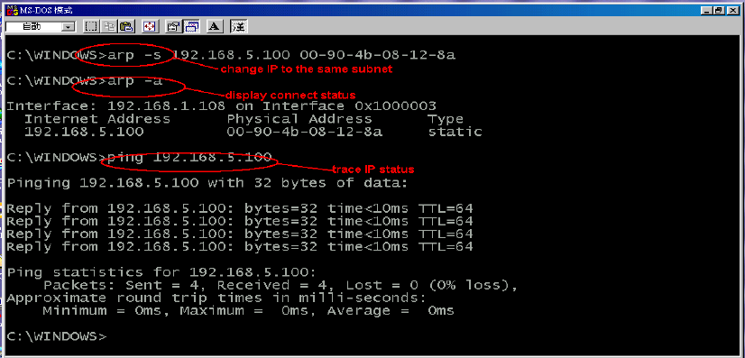
Step 3. Modify IP address to same subnet
Under DOS prompt and type
c:\>arp -s [IP address] [MAC address]
Note:
Arp: address resolution protocol
-s: change IP address
[IP address]: target IP address
[MAC address]: MAC address of Access Point
9
Step 4. Confirm IP address by using “ARP” instruction
Under DOS prompt and type
c:\>arp -a
10
Step 5. Trace IP address by using “Ping”
Under DOS prompt and type
c:\>ping [IP address]
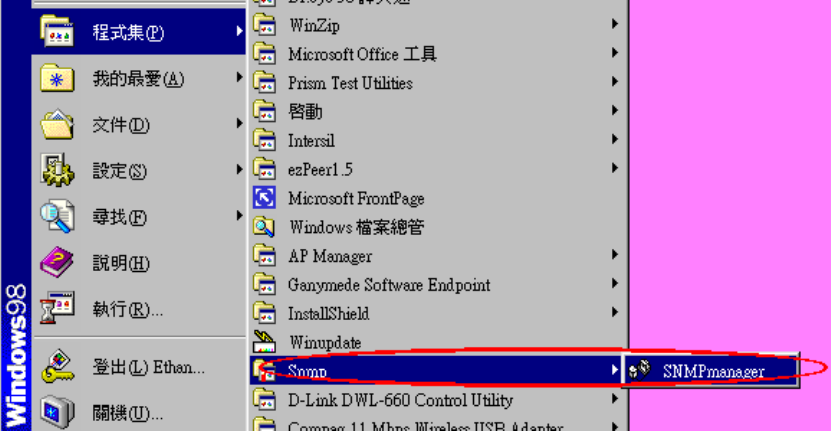
Step 6. Launch “AP SNMP” program
“Start” “Programs” “SNMP” “SNMP manager.
11
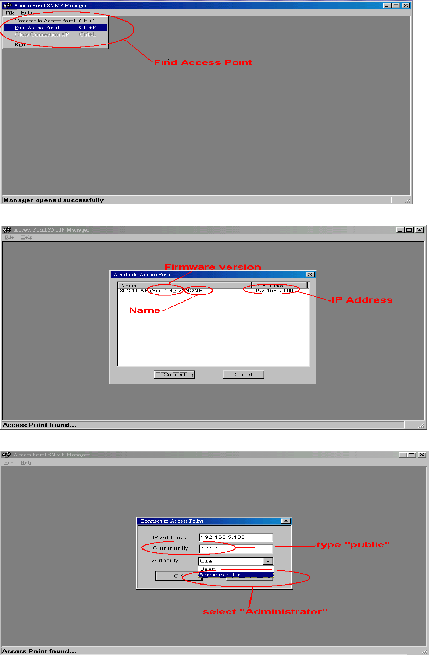
Step 7. Finding the associated Access Point
“File” “Find Access Point”
The list below shows all available Access Points,
Select the Access Point, which requires to control
Type “public” on community and select “Administrator” for logo-on authority, then click “OK”
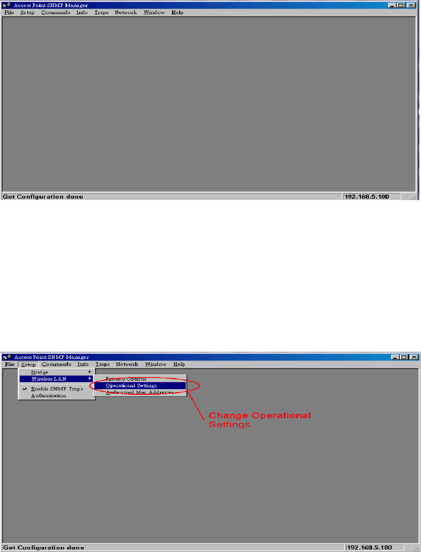
After Log-on the system, more function shows on the menu
12
Step 8. Function settings (Standard AP, AP Client, Wireless Bridge)
Here allow user to enter different configure settings.
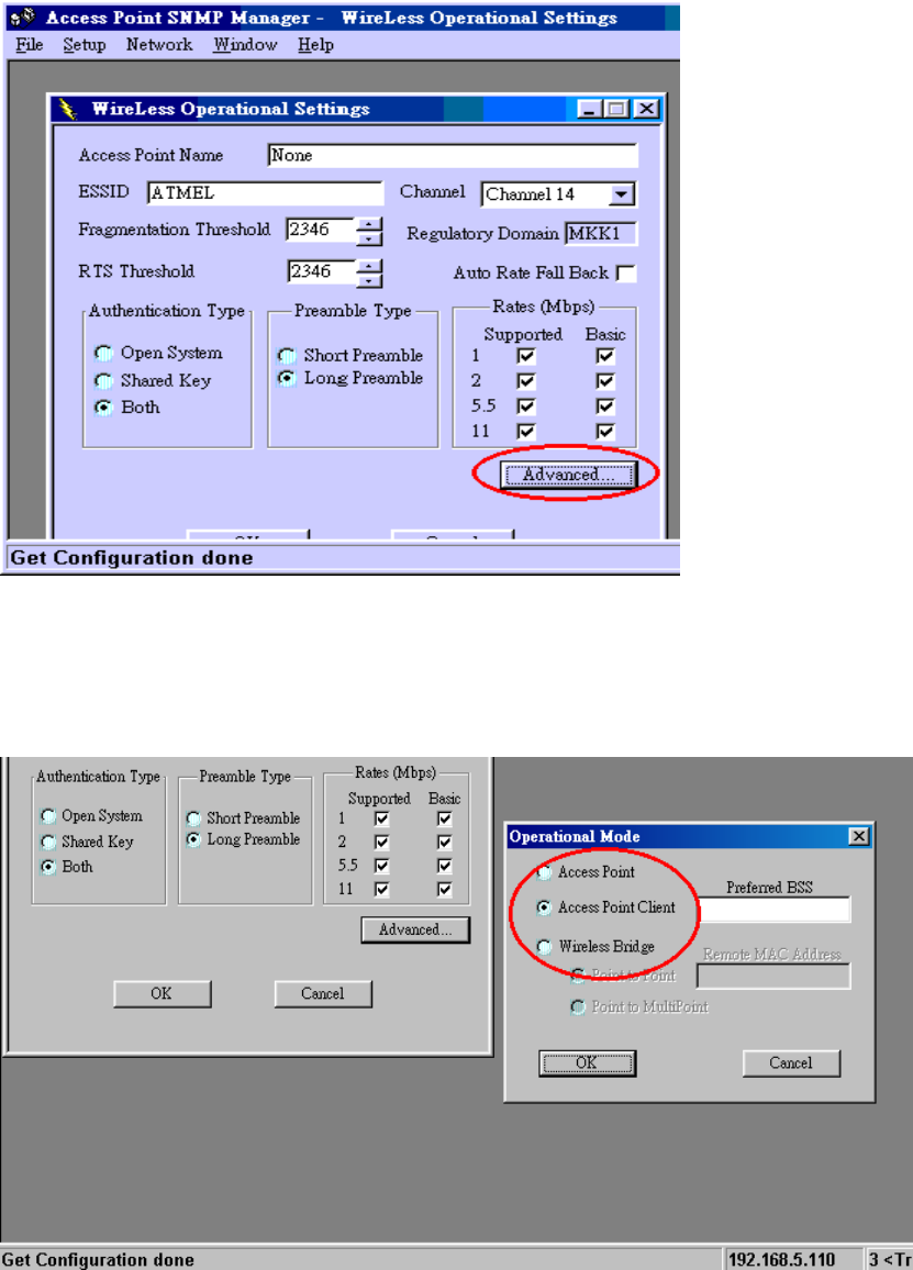
13
Click on Advanced button for different Operational Mode.
1. Click Access Point for standard AP function. Then click OK button.
2. For Access Point Client mode, please enter MAC address of the AP
(the AP you wish to associate with) in the Preferred BSS box.
Then click OK button.
14
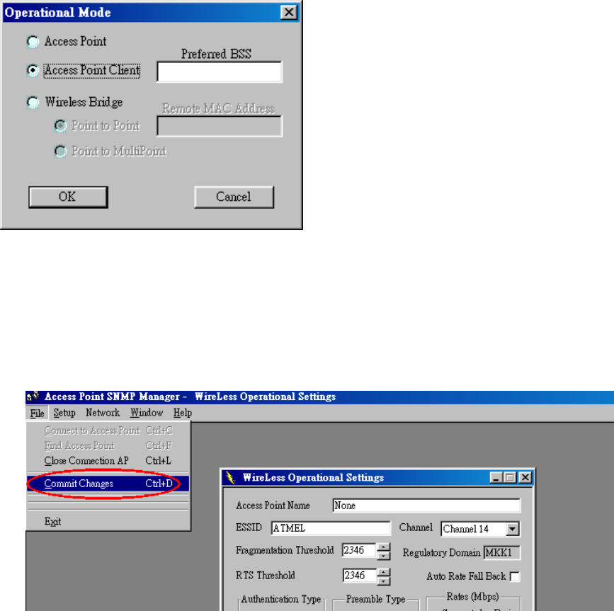
3. For Wireless Bridge mode, there are 2 options.
Point-to-Point: please enter the MAC address of remote Wireless Bridge.
Point to Multipoint
Then click OK button.
After finish the setting, please Commit Changes.
15
4. Glossary
BSS “Basic Service Set”. De facto an alias for Access
Point.
Cell Area in which the radio signal of an Access Point
is sufficiently good to join with it.
ESS “Extended Service Set”. A group of Access
Points with identical settings among which a
client system can roam. An ESS forms the heart
of a WLAN.
Shared Key Algorithm Encryption scheme for which both sender and
receiver need to know the (same) encryption
key.
SNMP “Simple Network Management Protocol”
WLAN “Wireless LAN” The set of Access Points and
Wireless Clients that form a local area network.
Write Community String SNMP password
WEP “Wired Equivalent Protection”
Data privacy mechanism based on a 40 bit
shared key algorithm, as described in the IEEE
802.11b standard

16
5. Technical specifications of Series Access Points
5.1 Standards supported
IEEE 802.11b standard for Wireless LAN
All major networking standards (including IP, IPX)
5.2 Environmental
Operating temperature (ambient):
-10 ~ 55°C
Humidity:
Max. 95% Non-condensing
5.3 Power specifications
DC power supply
Input: DC 100-240 50-60 Hz 1A
Output: 5V DC 1A converter incl.
5.4 Radio specifications
Range:
Per cell indoors approx. 35-100 meters
Per cell outdoors up to 100-300 meters
Transmit power:
Nominal Temp Range: 14 dBm, 12min.
Extend Temp Range: 14 dBm, 11 dBm min.
Transmit Power, 2.7 v to 3v: 14 dBm max, 11 dBm min.
Frequency range:
2.4-2.4835 GHz, direct sequence spread spectrum
Number of Channels:
Most European countries: 13
US and Canada: 11 (3 non-overlapping)
France: 4 (1 non-overlapping)
Japan: 14
Antenna system:
Dual antenna diversity system; 2dB gain with swivel neck
5.5 Specific features
Supported bit rates:
11 Mbps: CCK
5.5 Mbps: CCK
1 Mbps: DBSK
2 Mbps: DQPSK
Data encryption:
64/128-bit WEP Encryption
Utility Software:
AP Manager to manage wireless LAN, network connection and client access control
5.6 Physical Dimensions
152 x 111 x 40 mm
5.7 Weight
187 g