GemTek Technology A911028 Hotspot Acess Point User Manual Manual
Gemtek Technology Co., Ltd. Hotspot Acess Point Manual
Manual

Wi-Fi HiaB “Hot-Spot in a
Box”Access Point
P-360
User's Guide
Revision 0 December 25, 2002

Copyright © 2002 Gemtek Systems Holding BV
www.gemtek-systems.com

Gemtek Systems Page 4
Revision History
Revision Date Description Author
0November 6,
2002 Initial version of the document. Rasa Unguraityte

Gemtek Systems Page 5
Copyright
© 2002 Gemtek Systems Holding BV.
This user’s guide and the software described in it are copyrighted with all rights reserved. No part of
this publication may be reproduced, transmitted, transcribed, stored in a retrieval system, or translated
into any language in any form by any means without the written permission of Gemtek Systems
Holding BV.
Notice
Gemtek Systems reserves the right to change specifications without prior notice.
While the information in this manual has been compiled with great care, it may not be deemed an
assurance of product characteristics. Gemtek Systems shall be liable only to the degree specified in
the terms of sale and delivery.
The reproduction and distribution of the documentation and software supplied with this product and
the use of its contents is subject to written authorization from Gemtek Systems.
Trademarks
The product described in this book is a licensed product of Gemtek Systems Holding BV. All other
brand and product names are trademarks or registered trademarks of their respective.
Limited Warranty, Disclaimer
For a period two (2) year from the data of purchase.
National Radio Regulations
The usage of wireless network components is subject to national and or regional regulations and laws.
Administrator must ensure that they select the correct radio settings according to their regulatory
domain. Refer to the regulatory domains chapter in the appendix to get more information on
regulatory domains. Please check the regulations valid for your country and set the parameters
concerning frequency, channel, and output power to the permitted values!
Channel and output power settings may be modified by experienced service personnel only!
Wi-Fi “Hot Spot in a Box” Access Point P-360 User’s Guide
Rev.1

Contents
Gemtek Systems Page 6
Copyright..............................................................................................................................................5
Notice...................................................................................................................................................5
Trademarks..........................................................................................................................................5
Limited Warranty, Disclaimer...............................................................................................................5
National Radio Regulations .................................................................................................................5
CONTENTS.............................................................................................................................................6
ABOUT THIS GUIDE ..............................................................................................................................8
Purpose................................................................................................................................................8
Prerequisite Skills and Knowledge ......................................................................................................8
Conventions Used in this Document....................................................................................................8
Gemtek Systems Technical Support ...................................................................................................9
CHAPTER 1 – INTRODUCTION ..........................................................................................................10
Product Description............................................................................................................................10
Operating Modes ...............................................................................................................................10
Difference to P-320............................................................................................................................11
System Requirements........................................................................................................................11
The Product Package ........................................................................................................................11
LED’s..................................................................................................................................................12
CHAPTER 2 – INSTALLATION............................................................................................................13
Hardware Installation .........................................................................................................................13
Attaching the Access Point to the Wall ..........................................................................................13
Removing the Access Point from the Wall.....................................................................................14
Software Installation...........................................................................................................................14
Find Your New P-360! .......................................................................................................................14
Test: Calling P-360 with Ping.............................................................................................................15
CHAPTER 3 - CONFIGURATION ........................................................................................................16
Accessing the Web Manager Interface..............................................................................................16
Device Status.....................................................................................................................................18
System Status ................................................................................................................................18
Service/Interface Status .................................................................................................................18
Network Status...............................................................................................................................19
Network Statistics...........................................................................................................................19
Setup Wizard .....................................................................................................................................21
General Configuration Settings......................................................................................................21
Network Configuration Settings......................................................................................................22
Wireless Configuration Settings.........................................................................................................24
Access Point SSID.........................................................................................................................24
Domain/Channel.............................................................................................................................24
Encryption Algorithm ......................................................................................................................25
ACL Settings ..................................................................................................................................26
Firewall Settings.............................................................................................................................27
Isolation Settings............................................................................................................................30
Routing Settings.............................................................................................................................30
DHCP Settings ...............................................................................................................................31
Port Forwarding Settings................................................................................................................32
Administrator’s Settings .................................................................................................................33
Contents

Contents
Gemtek Systems Page 7
802.1x Settings...............................................................................................................................34
PPPoE Settings..............................................................................................................................36
PPTP 36
QoS 37
Redirect Settings............................................................................................................................37
Load Balance .................................................................................................................................38
System Tools .....................................................................................................................................39
Clients 39
Loopback Test................................................................................................................................39
SNMP Settings...............................................................................................................................40
Site Survey.....................................................................................................................................43
Monitoring.......................................................................................................................................43
Upgrade 44
Reboot 45
Reset Device..................................................................................................................................46
REFERENCE GUIDE............................................................................................................................48
TROUBLESHOOTING..........................................................................................................................50
GLOSSARY ..........................................................................................................................................53
INDEX....................................................................................................................................................54

Gemtek Systems Page 8
Purpose
This document provides information and procedures on hardware installation, setup, configuration,
and management of the Gemtek Systems Wi-Fi ‘Hot-Spot in the Box’ Access Point model P-360.
Prerequisite Skills and Knowledge
To use this document effectively, you should have a working knowledge of Local Area Networking
(LAN) concepts and wireless Internet access infrastructures. In addition, you should be familiar with
the following:
! Hardware installers should have a working knowledge of basic electronics and mechanical assembly,
and should understand related local building codes.
! Network administrators should have a solid understanding of software installation procedures for
network operating systems under Microsoft Windows 95, 98, Millennium Edition, 2000, NT, and
Windows XP and general networking operations and troubleshooting knowledge.
Conventions Used in this Document
The following typographic conventions and symbols are used throughout this document:
Very important information. Failure to observe this may result in damage.
Important information that should be observed.
Additional information that may be helpful but which is not required.
bold Menu commands, buttons and input fields are displayed in bold
code File names, directory names, form names, and system-generated output
such as error messages are displayed in constant-width type
<value> Placeholder for certain values, e.g. user inputs
note Comments or hints
About this Guide

Gemtek Systems Page 9
Help Us to Improve this Document!
If you should encounter mistakes in this document or want to provide comments to improve the
manual please send e-mail directly to:
manuals@gemtek-systems.com.
Gemtek Systems Technical Support
If you encounter problems when installing or using this product, please consult the Gemtek Systems
website at
http://www.gemtek-systems.com for:
• The latest software, user documentation and product updates.
• Frequently Asked Questions (FAQ).
• Direct contact to the Gemtek Systems support.

Gemtek Systems Page 10
Thank you for choosing the Gemtek Systems Wi-Fi ‘Hot-Spot in the Box’ Access Point model P-360.
With this product the Gemtek Systems want to deliver a carrier class 11Mb WLAN Access Point
specially designed for single-cell hot-spot applications with an integrated Public Access Controllers
(model G-6000/G-4000).
Product Description
The P-360 “Hot-Spot in a Box” Access Point (HiaB) is a stand-alone network device designed to
provide user-friendly wireless public access services. It is a WLAN Access Point that supports
authentication, accounting, and security mechanisms that enable operators to instantly deliver
commercial Internet services to customers.
Product Features
Aprashyti featurus produkto: some features description in several sentences.
P-360 Highlights
• 2.4 GHz, IEEE 802.11b, 11Mbps Wi-Fi Access Point
• Integrated high-gain diversity antennas
• Power-Over-Ethernet
• Theft protection system
• User Isolation (Layer 2)
• Web-based and 802.1x/EAP authentication
• AAA RADIUS/EAP client
• IP Routing , NAT, Firewall, PPTP. PPPoE
• 64/128-bit WEP security on wireless transmissions
• Programmable RF Output Power Management
• Site/Clients Survey
• Private Gemtek MIB
• Management via HTTPs, Telnet, SSH and SNMP
• Remote software upgrade
• Copy protection
Operating Modes
Aprashyti abu operation modes, kas ten vyxta.
Chapter 1 – Introduction

Gemtek Systems Page 11
The P-360 HiaB Access Point can work in different operation modes:
• Access point mode (AP)
• Access Point-Router mode (AP-Router)
Difference to P-320
The P-360 WLAN AP is designed to cooperate with G-6000/G-4000 hot-spot gateways. As opposed
to P-320 (Wi-Fi Operator Access Point) the P-360 does incorporate routing and the Universal Access.
However, P-360 can be configured as a 802.1x authenticator. In this setup the G-6000/G-4000
gateway will act as a RADIUS-Proxy and controls the traffic flow. Only when 802.1x authentication
chain is successfully finished the gateway will allow Internet access.
P-360 is also called “A Hot-spot in a box”, because it incorporates all necessary AAA features for
single-cell hot-spots. P-360 typically works as a router, whereas P-320 is used as a layer2 bridge
between wireless clients and an Ethernet backbone.
P-320 and P-360 share one hardware platform incl. housing. However it is not possible for users to
upgrade from P-320 to P-360 by software (or vice versa).
System Requirements
• Network Adapter with Ethernet (UTP CAT 5) Cabling and TCP/IP installed per PC
• Web browser with enabled Java and JavaScripts for Web-based Manager
• Cable Modem with Ethernet Connection and Internet Access
• Windows operating system for AP search and AP upgrade tools
The Product Package
Each ”Hot-Spot in a Box” Access Point comes with the following:
• One P-360 model Access Point
• One Twisted-pair LAN cable
• One wall mounting assembly kit
• One CD-ROM containing this User’s Guide in the Portable Document Format (PDF)
If any of these items are missing or damaged, please contact your reseller or Gemtek System
Technical Support.

Gemtek Systems Page 12
LED’s
The HiaB Access Point has a several LED’s located at the front side.
1. Wireless activity LED
Off: no activity
Blinking: sending and receiving data
2. LAN link LED
Off: No LAN connection available
On: LAN connection OK
3. Power LED
Off: Power supply connection not available or broken
On: Power supply connection OK
Figure 1 – Front Side LED’s

Gemtek Systems Page 13
This chapter describes how to install Wi-Fi “Hot-Spot in a Box” Access Point. The hardware and
software installation instructions are provided here.
Hardware Installation
Before you connect the Access Point, decide where to place it.
Determinate the best location of the Wi-Fi Access Point, keeping in mind the following considerations:
•
The length of the Ethernet cable that connects the Access Point to the network must not exceed 100 meters.
•
The power source must be next to the installation place.
• Try to place the Access Point in a dry, clean location as far from the ground as possible, such
as on top of a desk or bookcase, keeping clear of metal obstructions.
• Try to place the Access Point away from transformers, heavy-duty motors, fluorescent lights,
microwave ovens, refrigerators, or other equipment that could cause radio signal interference.
• Try to centrally locate the Access Point to provide the best coverage of the area.
Attaching the Access Point to the Wall
1. Place the Access Point in the desired location. Use the wall mounting assembly kit available with
P-360 Access Point. Follow the instructions:
• Attach the wall mounting clamp to the wall with the spring latch to the upper side using the
four enclosed screws.
• Connect the rear side of the Access Point to the mounting plate:
Figure 2 -- Attaching the P-320 housing to the mounting clamp
• Move the housing slightly upwards until the spring latch is locked in place. The P-320
Operator Access Point is now securely mounted onto the wall and can not be removed
without special tools.
2. Insert the twisted pair LAN cable to a Power-over-Ethernet socket. At least the power LED and
the LAN link LED should light up.
Chapter 2 – Installation

Gemtek Systems Page 14
Removing the Access Point from the Wall
1. Open the housing of the Access Point by pressing the spring latches on the upper rear side of the
access point using the disassembling tool delivered with your P-360.
Figure 3 -- Removing the P-360 housing using the disassembling tool
2. Release the housing from the wall mounting clamp by carefully pressing the spring latch in the
center of the device (see Figure 3 -- Removing the P-360 housing using the disassembling tool)
using the small edge of the disassembling tool.
3. Move the housing slightly downward and remove it.
Software Installation
Insert the installation CD delivered with your new P-360 Access Point into your CD-ROM drive.
The installation wizard starts automatically and will guide you through the rest of the installation
process. If the installation wizard does not start automatically, please run “autorun.exe” manually
from the root directory of the installation CD.
Software is needed for setup and management of the P-360 HiaB Access Point.
In general, there are four different ways to access the device:
• Windows applications: AP search and AP upgrade (installation required)
• Standard HTML browser (Java and JavaScript enabled) using Configuration Manager
• CLI (command line interface)
• SNMP
Find Your New P-360!
To find your new P-360 HiaB Access Point you will need to connect the AP to the same logical
network as your PC. The standard IP address of the P-360 in factory default status is 192.168.2.2. To
access the P-360 in its default configuration you will need to use one of the following IP settings in
your network:
• IP address space 192.168.x.x
• Subnet mask 255.255.0.0

Gemtek Systems Page 15
Test: Calling P-360 with Ping
To test the accessibility of your P-360 from your PC, just type the following from a command prompt:
ping 192.168.2.2
If ping replays, you can access the P-360 from this PC. Otherwise there is a problem accessing the P-
360 in default status from this PC. You should either change the IP address of your PC or of the P-
360.
Gemtek Systems Page 16
The configuration manager provides the user interface to configure and manage HiaB Access Point
(P-360). When the Access Point is installed, access the user interface using the standard Web
browser such as Internet Explorer 6 or Netscape Navigator 6 (Java and JavaScript enabled).
This chapter includes the following subsections:
• Authentication
• System Status
• Setup Wizard
• Advanced Settings
• System Tools
Accessing the Web Manager Interface
3. Open a Web browser on a network computer.
4. In the Address or Location field, enter the IP address of a HiaB Access Point on the network.
For example if the IP address for HiaB is 192.168.2.2, type: http://192.168.2.2 to access the Web
Manager.
Your Web browser session is automatically redirected to the secured connection to
the device (https).
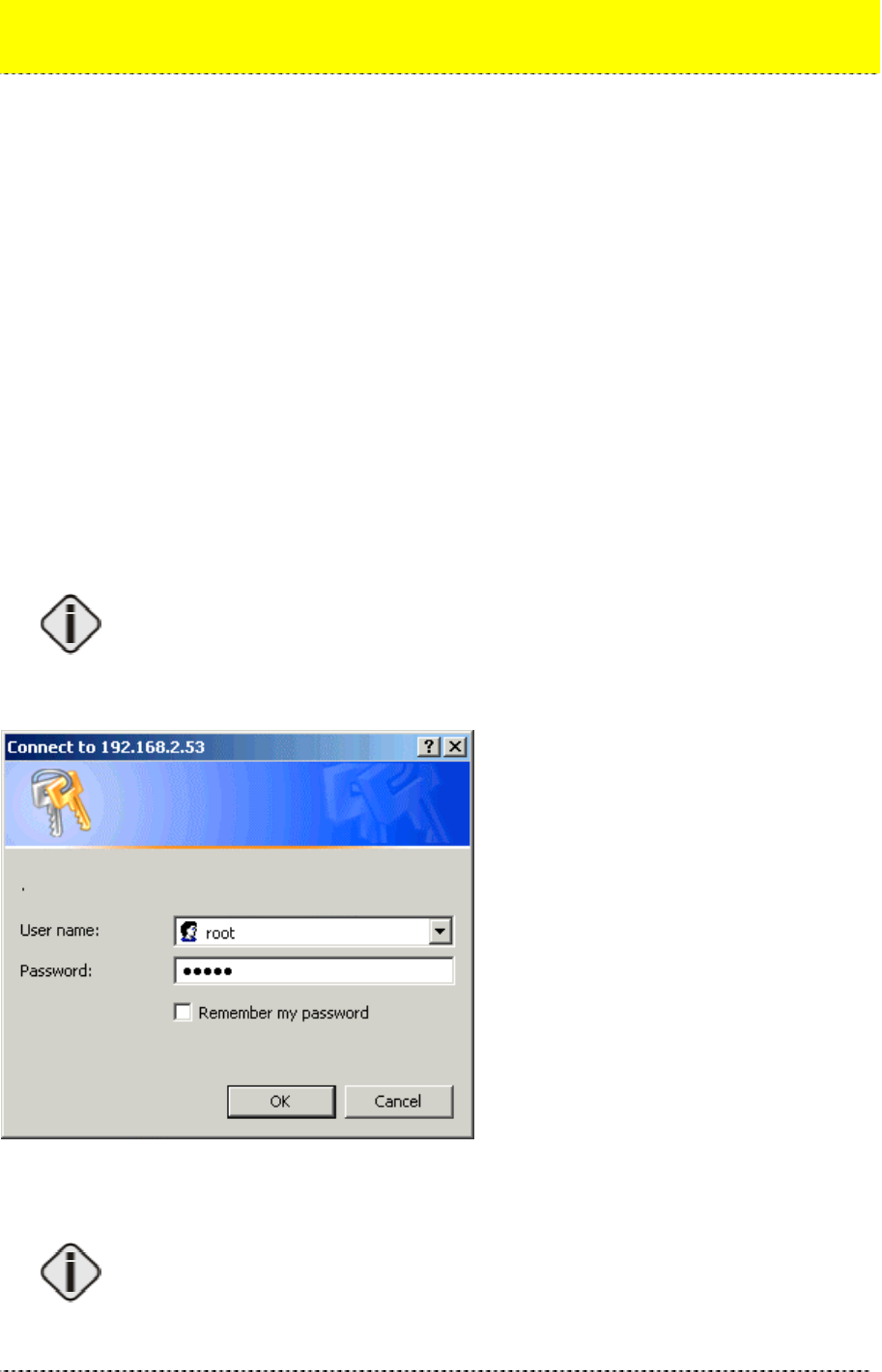
5. The Network Authentication dialog appears as shown in the example:
Figure 4 – Login to the Web Manager
Enter default login settings: root as user name and pass as password.
The default user name is fixed and cannot be changed. Password can be managed
using the Advanced Settings menu.
Chapter 3 - Configuration

Gemtek Systems Page 17
After successful authentication the Web Manager user interface is displayed as following:
Figure 5 – Main Web Manager Page
The device status headline is displayed in the upper part of the screen. Some general information of
this device is provided here:
Figure 6 -- Status Headline
SSID of the device
Uptime since last reboot
Average Load of processor
Number of Clients currently connected to this device.
In the next subsections different configuration Web Manager parts are described.
Gemtek Systems Page 18
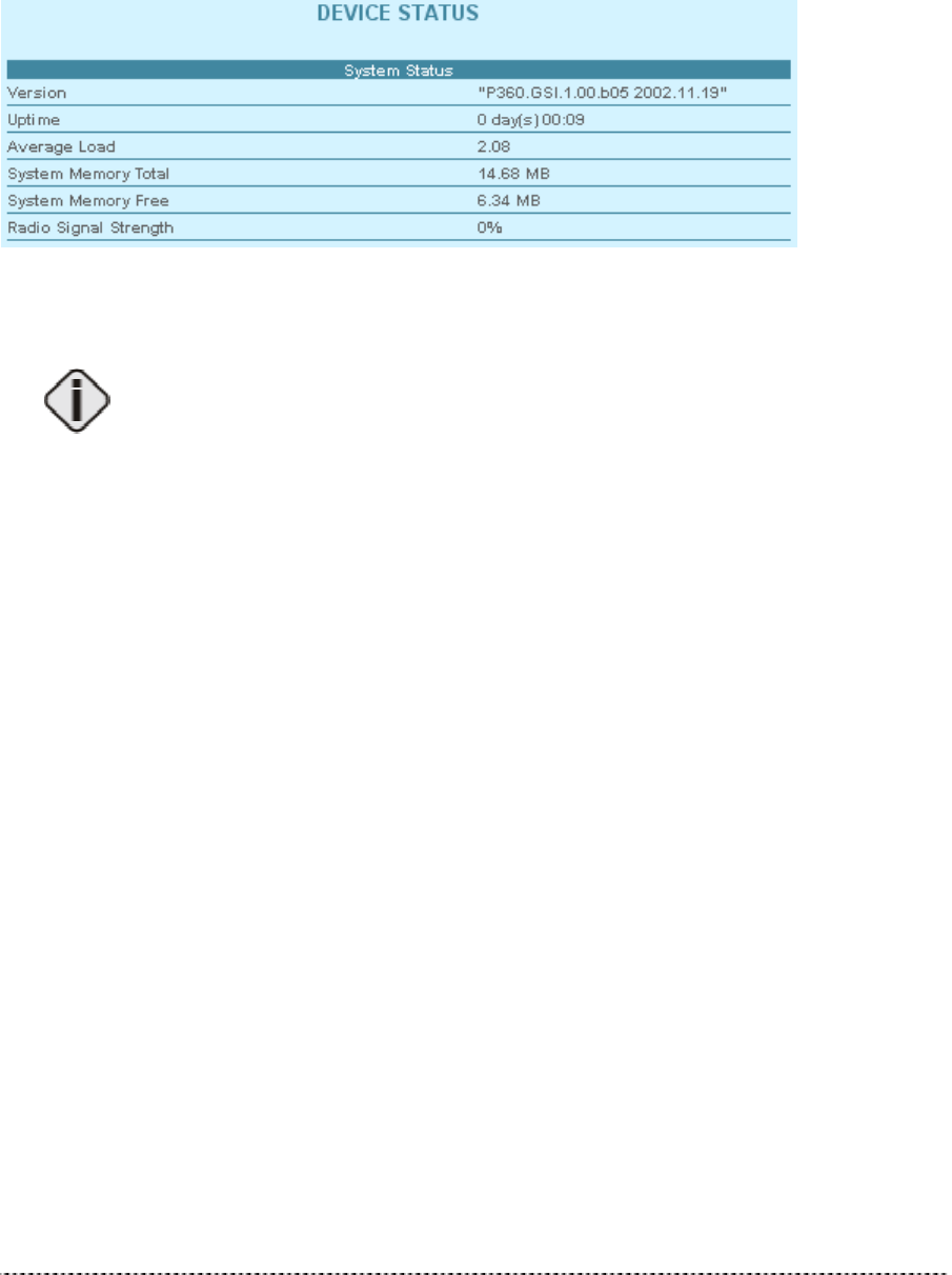
Device Status
The device status page shows some information about the HiaB P-360 itself, its loaded services, its
operating mode and position in your network and the data traffic on the wireless interface.
System Status
Figure 7 – Device Status (1)
Version is the current version of the firmware.
This is important information for support requests and for preparing firmware
uploads.
Uptime is the time in days since last system reboot.
Average Load shows the average load of the P-360 processor.
System Memory Total shows the total P-360 memory.
System Memory Free shows the currently available P-360 memory.
Radio Signal Strength shows ?????
Service/Interface Status
Different services status (enabled/disabled) and WAN interface status is provided in the following
status table:
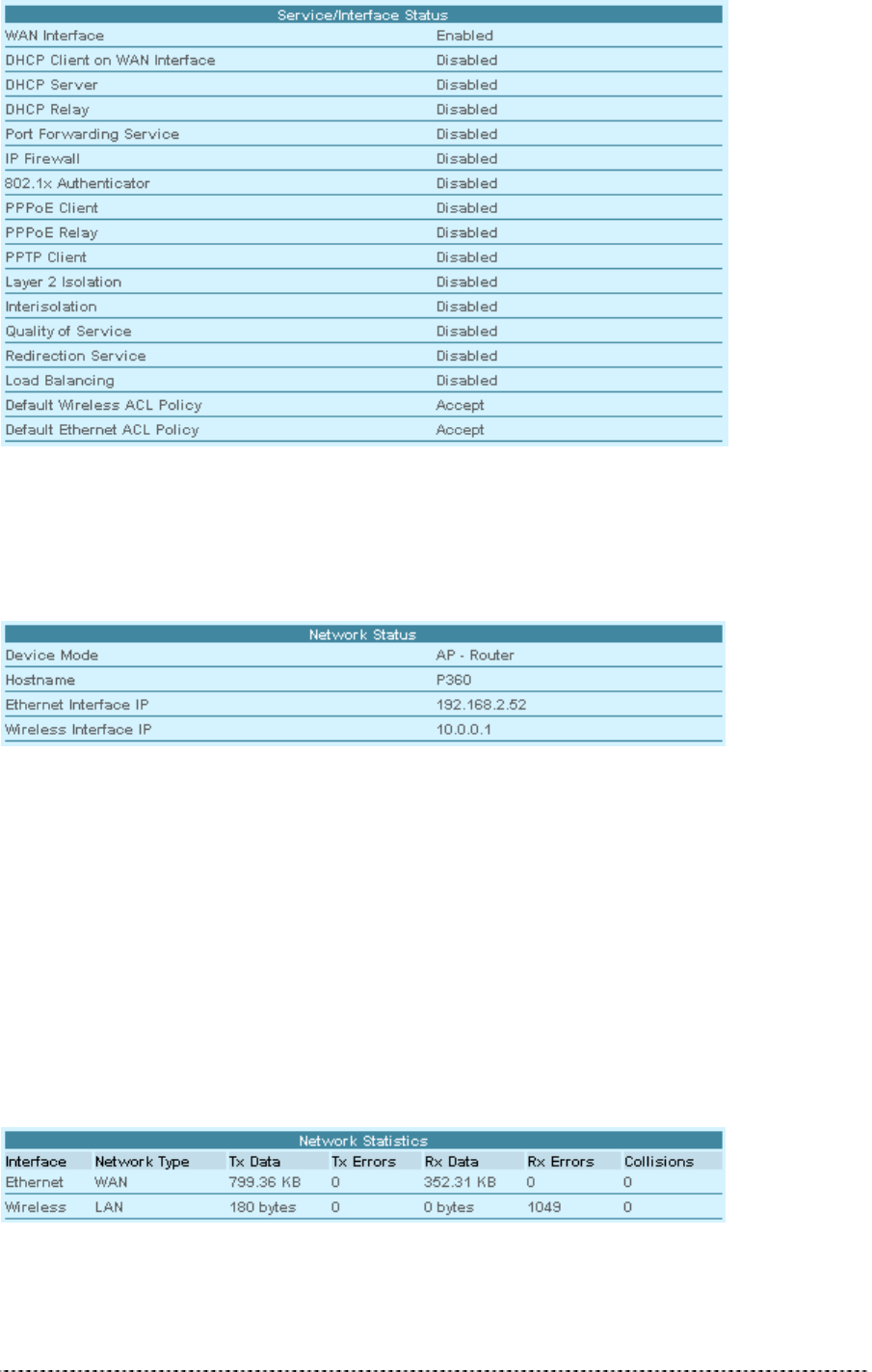
Gemtek Systems Page 19
Figure 8 – Device Status (2)
Network Status
Figure 9 – Device Status (3)
Device Mode shows the P-360 operating mode (AP or AP Router).
Hostname shows the name of the P-360 in the network used for statistic routines.
Ethernet Interface IP shows IP address of the Ethernet interface of the P-360.
Wireless Interface IP is the IP address of the wireless interface of the P-360.
Network Statistics
In the list of all Interfaces you can find information about the data traffic on the wireless interface:
Figure 10 – Device Status (4)
Tx Data is data volume transmitted successfully.

Gemtek Systems Page 20
Tx Errors are errors while transmitting data.
Rx Data are data volume received successfully.
Rx Errors are errors while transmitting data.
Collisions are number of data packet collisions.
Gemtek Systems Page 21
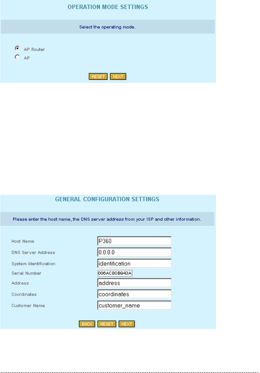
Setup Wizard
On the first page of the Setup Wizard available ‘Hot-Spot in a Box’ device modes are listed:
Figure 11 – Device Operating Modes
Select AP – Router mode, if you want to allow mobile stations to access your wired network and you
need to build up a wireless connection to a different IP subnet.
Select AP mode, if you want to allow mobile stations to access your wired network.
General Configuration Settings
On the general settings page you can specify information about the name and location of your P-360.
Figure 12 -- General Configuration Settings
Host Name is the name under which the device will appear for example in the AP Search tool.
Gemtek Systems Page 22
DNS Server Address is the IP address of a domain name server. This IP address, provided by your
ISP, will be assigned to all PCs requesting address information through DHCP from the P-360.
Available in AP-Router mode only!
If you are not sure about the IP address of the DNS server currently responsible for
your local network, please get your IP configuration with “ipconfig” (Win 2000, Win
NT and Win XP) or “winipcfg” (Win 9x and Win Me) from the command prompt.
System Identification is a more specific device name for better identification by service staff.
Serial Number is the MAC address of the device and cannot be modified!
Address is the street and postal address of the location where the device is deployed.
The Coordinates specifies the longitude and latitude or other coordinates of the device location.
Customer Name is the customer’s name.
All of the parameters above on the general configuration setting page are required!
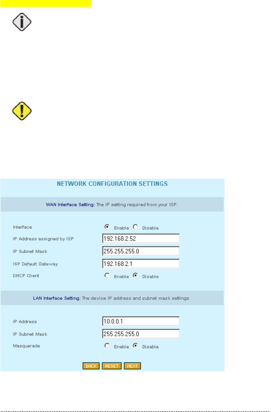
Network Configuration Settings
On the network configuration settings page you can modify the IP settings for the P-360 and the
default gateway.
Figure 13 – Network Configuration Settings

Gemtek Systems Page 23
WAN Interface Settings:
Interface: Use this option to switch the WAN interface of P-360 on (Enable) or off (Disable).
Available in AP-Router mode only!
In AP-Router mode you disable the wired interface to the Ethernet using this radio
button. When the interface is disabled, there are no connections possible between
Ethernet devices and the P-360.
IP Address assigned by ISP is the device’s IP address on the WAN interface. If the DHCP client
function is enabled, the IP address assigned by the DHCP server will be used. If no DHCP server can
be found via WAN interface, the IP entered here will be used.
If you change the IP address manually, please make sure that the chosen IP
address is free and belongs to the same IP subnet as the old one. Otherwise you
will loose the connection to the P-360 from your current PC. If you enable the
DHCP client via web browser, the browser will loose the connection after rebooting,
because the IP address assigned by the DHCP server is not predictable.
IP Subnet Mask is the corresponding network mask for the IP address on the WAN interface.
ISP Default Gateway is the gateway to other networks on WAN side.
DHCP Client: enable this option, when a DHCP server is running in the network on WAN side and
you want the DHCP server to assign a free IP address the WAN interface of P-360.
If you are not sure about the IP address of the gateway currently responsible for
your local network or DHCP server please get your IP configuration with “ipconfig”
(Win 2000, Win NT and Win XP) or “winipcfg” (Win 9x and Win Me) from the
command prompt.
LAN Interface Settings (AP-Router mode only):
IP Address is the device’s IP address on the LAN interface. In AP-Router mode this is the IP address
on the wireless interface, in client router mode it is the IP address on the wired (Ethernet) interface.
If you enable the DHCP server on the wireless interface in AP-Router mode, please
make sure that the IP address inserted for the wireless interface here is in the
same IP subnet as the IP address pool range of the DHCP server.
IP Subnet Mask is the corresponding network mask for the IP address on the LAN interface.
Please make sure that you use different IP subnets for the WAN and LAN
interfaces. If both address spaces are in the same IP subnet, all routing functions
will be disabled!
Masquerade: When you enable this function, the router will use his network address translation (NAT)
function. In this case all LAN IP addresses are hidden to the WAN network behind the routers WAN IP
address. The P-360 in AP router mode on the other side of the wireless network will forward the data
packets using his own WAN IP address to the wired (Ethernet) network it is connected to.
Gemtek Systems Page 24
Wireless Configuration Settings
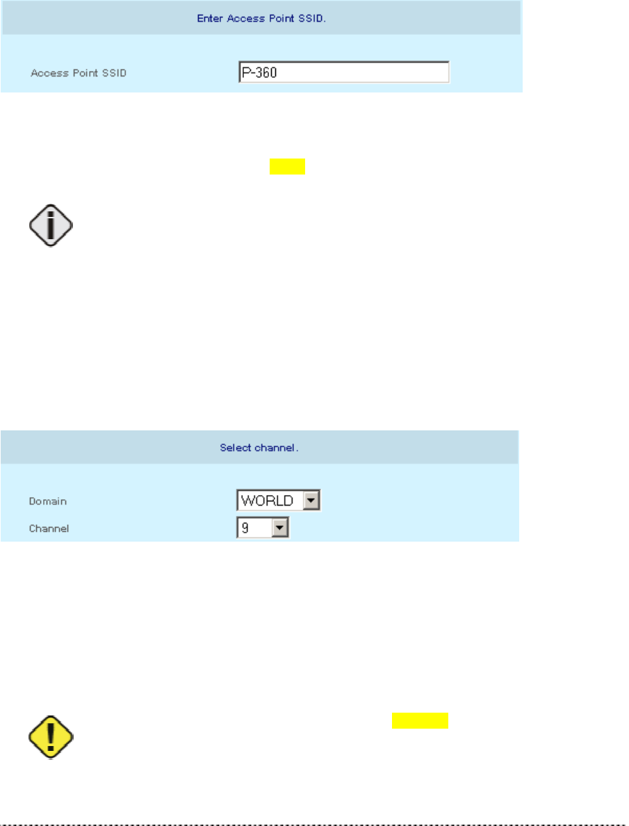
Access Point SSID
Depending on the device mode selection, parameters available in the Wireless Configuration Settings
page will vary. Because of the complexity and quantity the wireless parameters are spitted into the
simple units.
Figure 14 -- Wireless Configuration Settings (1)
Access Point SSID is a unique name for your wireless network. It is case sensitive and must not
exceed 32 characters. The default SSID is "xxxxx " but you should change this to a personal wireless
network name.
The SSID may not contain special characters like [ ] { } / \ or spaces. Only dots and
underscores are allowed.
In Access Point mode SSID must be made known to all mobile clients, or they have to use the “auto
connect to any wireless network” function in their WLAN card.
If you are running more than one P-360 and want to enable the roaming function, please use the
same SSID in all access points.
Domain/Channel
Figure 15 – Wireless Configuration Settings (2)
Domain: full frequency range of the 2.4 GHz ISM band is not permitted to be used in all countries.
Depending on the selection of the regulatory domain here the available frequency channels will vary.
Channel: Frequency channels are used to avoid interference between nearby access points. If you
wish to operate more than one access points in overlapping coverage areas, we recommend a
distance of at least four channels between the chosen channels. For example, for three Access Points
in close proximity choose channels 1, 5 and 11.
Refer to the regulatory domains chapter in the appendix to get more information
concerning the regulations valid for your country and set the parameters for
frequency channel to the permitted values!

Gemtek Systems Page 25
Encryption Algorithm
Figure 16 -- Wireless Configuration Settings (3)
Select No, 64-Bit or 128-Bit Encryption.
Key 0 to 3: The WEP keys are entered as a series of colon-separated HEX pairs:
5 pairs for 64-Bit (e.g. 00:AC:01:35:FF)
13 pairs for 128-Bit (e.g. 00:11:22:33:44:55:66:77:88:99:AA:BB:CC).
Also select the active key radio button next to appropriate key.
The encryption key must also be entered into the WLAN card configuration of the mobile clients.
Gemtek Systems Page 26
Advanced Settings
Setting up the P-360 advanced settings requires advanced knowledge of the
TCP/IP network structure and functionalities. It is recommended that only skilled
network administrators should use these settings.
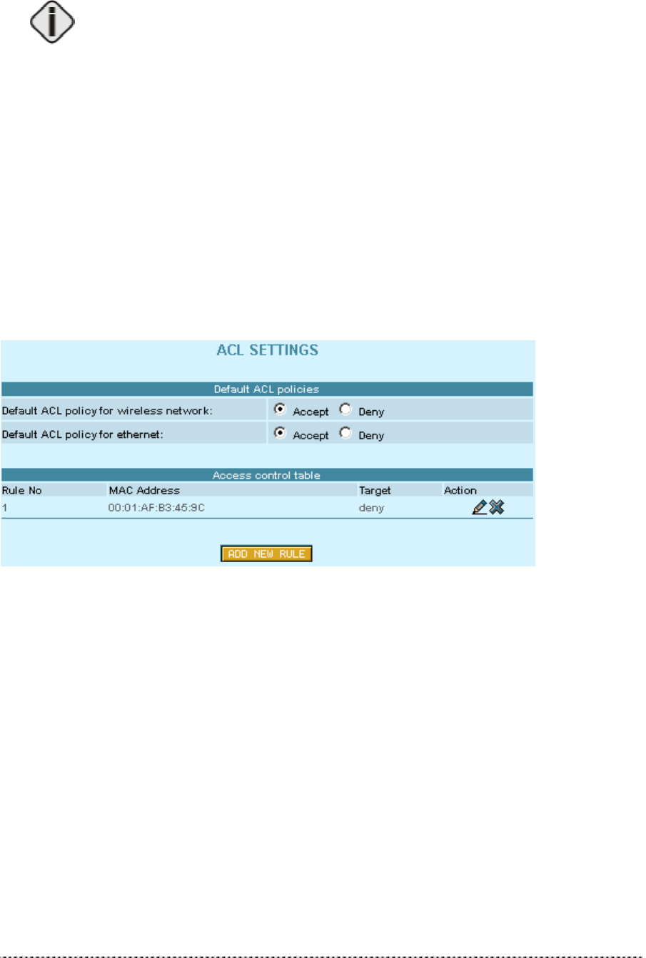
ACL Settings
In the ACL Settings page you can specify default access policy for wireless or Ethernet network
devices.
Default ACL policy for wireless network: Select Accept to allow all mobile clients to access this
access point or Deny to prevent all mobile clients from access to your access point. Clients may also
be subject to rules in the Access control table.
Default ACL policy for Ethernet: Select Accept to allow all LAN clients to access this access point
or Deny to prevent all LAN clients from accessing your access point. Clients may also be subject to
rules in the Access control table.
Figure 17 – ACL Settings
If you need to define special access rules for specific network devices, you can create your own
access list. Access control list is based on the networks devices’ MAC address. Just specify network
device MAC address and it’s access policy (accept/deny) with new rule in the Access control table.
Click the Add New Rule button and define new specific rule in the following page:

Gemtek Systems Page 27
Figure 188 – Add New ACL Rule
• Specify the MAC address of the device you want to add to the ACL. The format is a list of colon
separated hexadecimal numbers (for example: 00:00:78:0A:CD:FF).
• Select the Target of the rule, whether the specified network device should be allowed or denied
as an Access Points client.
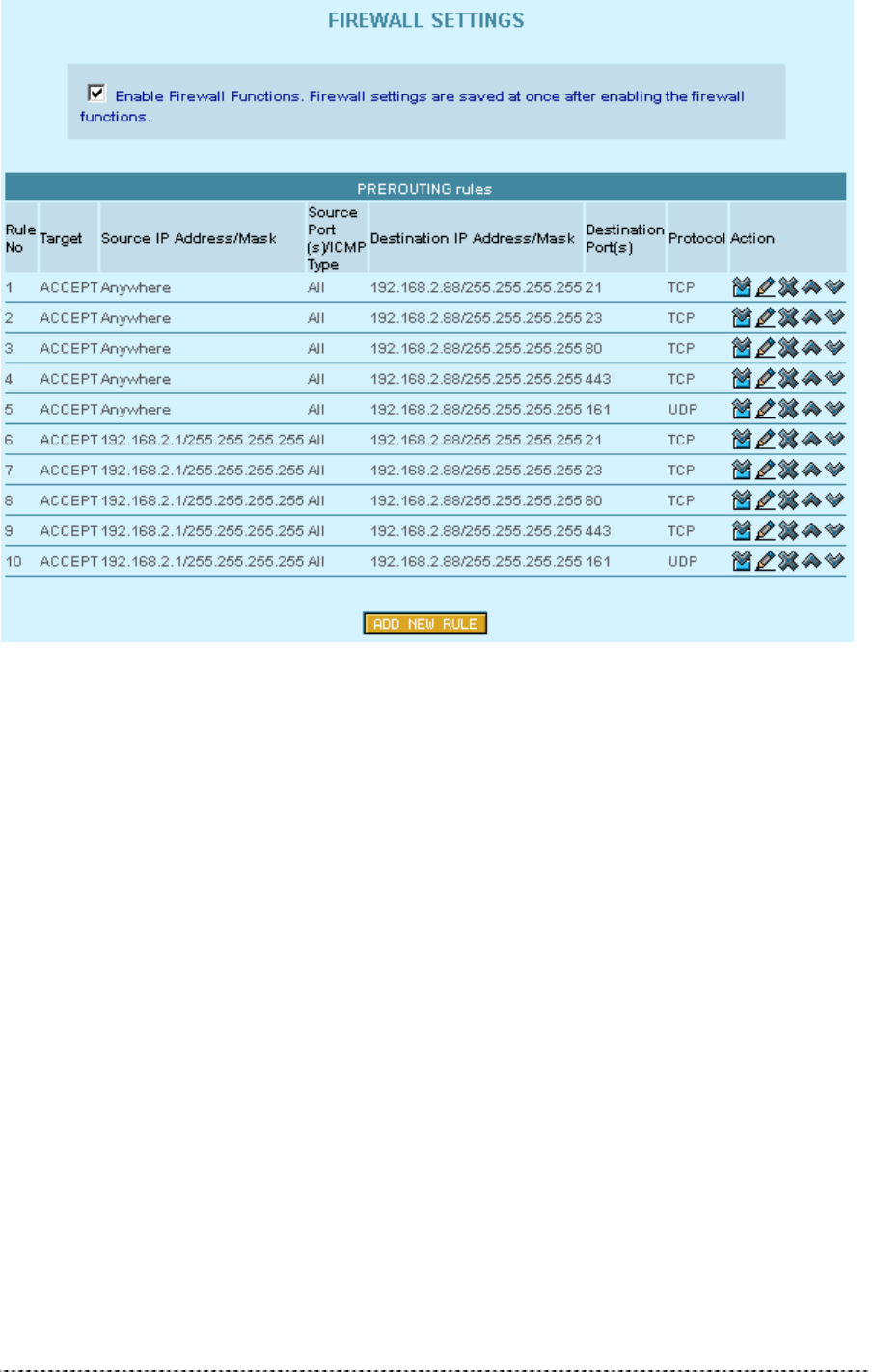
Firewall Settings
The firewall settings allow to specify IP packet filters to enhance the data security. The firewall takes
effect between LAN and WAN and is supposed to avoid forbidden intrusion to your local network. The
firewall rules are divided into Input and Output (in AP router operating mode) or Prerouting (in AP
mode) rules to assign special procedures to a certain data transmission direction.
Gemtek Systems Page 28
Figure 19 – Firewall Settings
On the main firewall settings page you will find one table for input, output or prerouting rules and a
switch to enable or disable the firewall. Within the tables you can insert new rules, modify existing
ones, delete rules and change their position by moving up or down.
The position of a rule within the list is very important, because the list is worked through from top to
down. If a packet is dropped in the first lines by a very general rule, it does not help to accept it further
down with a more specific rule. So please check the rules right position after defining or modifying
them.
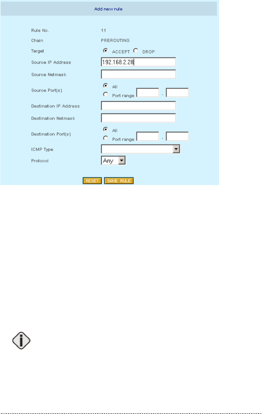
To specify a new firewall rule please click Add New Rule and choose type of rule, it’s source,
destination parameters.
Gemtek Systems Page 29
Figure 190 – Add New Firewall Rule
Target – this implementation of firewall control supports two types of rules – Accept and Drop. The
appropriate policy defines what to do if the data packet received matches the rule.
Source IP Address – source IP address.
Source Netmask – source netmask IP address.
Source Port(s) – can be specified in two ways: “All” or a given port range.
Destination IP Address – specified the same as Source IP.
Destination Netmask – specified the same as source netmask.
Destination Port(s) – specified the same as Source port.
Protocol – network protocol, which affects the rule. Can be specified as one of TCP/UDP/ICMP or
“any”.
ICMP Type – if ICMP network protocol is selected, then the appropriate protocol type can be chosen.
Leave the Source/Destination IP and Netmasks fields empty if you want to specify it
as “any”.
Gemtek Systems Page 30
Isolation Settings
Figure 201 -- Layer 2 Isolation
Routing Settings
Routing Settings is available when the access point is in AP-Router operation
mode.
Opening the page you will find a list of all present routes, each consisting of the related interface, the
destination IP address, the gateway and the subnet mask. The default values in this list are generated
from your current IP settings in the Network Configuration Settings menu.
The routing list shows, how the router will handle data packets received on an interface at destination
to a specific IP address. In this example, all data received on the Ethernet interface with an
destination IP address in the 192.168.2.0 network will be forwarded to the default gateway. All other
data packets received on the Ethernet interface will be forwarded to the gateway 192.168.2.1.
If there is more than one route specified for one destination, the metric value shows the priority, how
the router will try the routes. The metric value indexes the number of gateways between sender and
destination.

Gemtek Systems Page 31
Figure 212 – Static Routing Settings
To create a new static route please click Add New Route and select the related interface
(Ethernet/wireless), specify destination, netmask and gateway IP, and metric values. Click the Save
Route to add new static route in the Routing table.
Figure 223 -- Add Static Route
Destination, Netmask and Gateway are required parameters to specify.
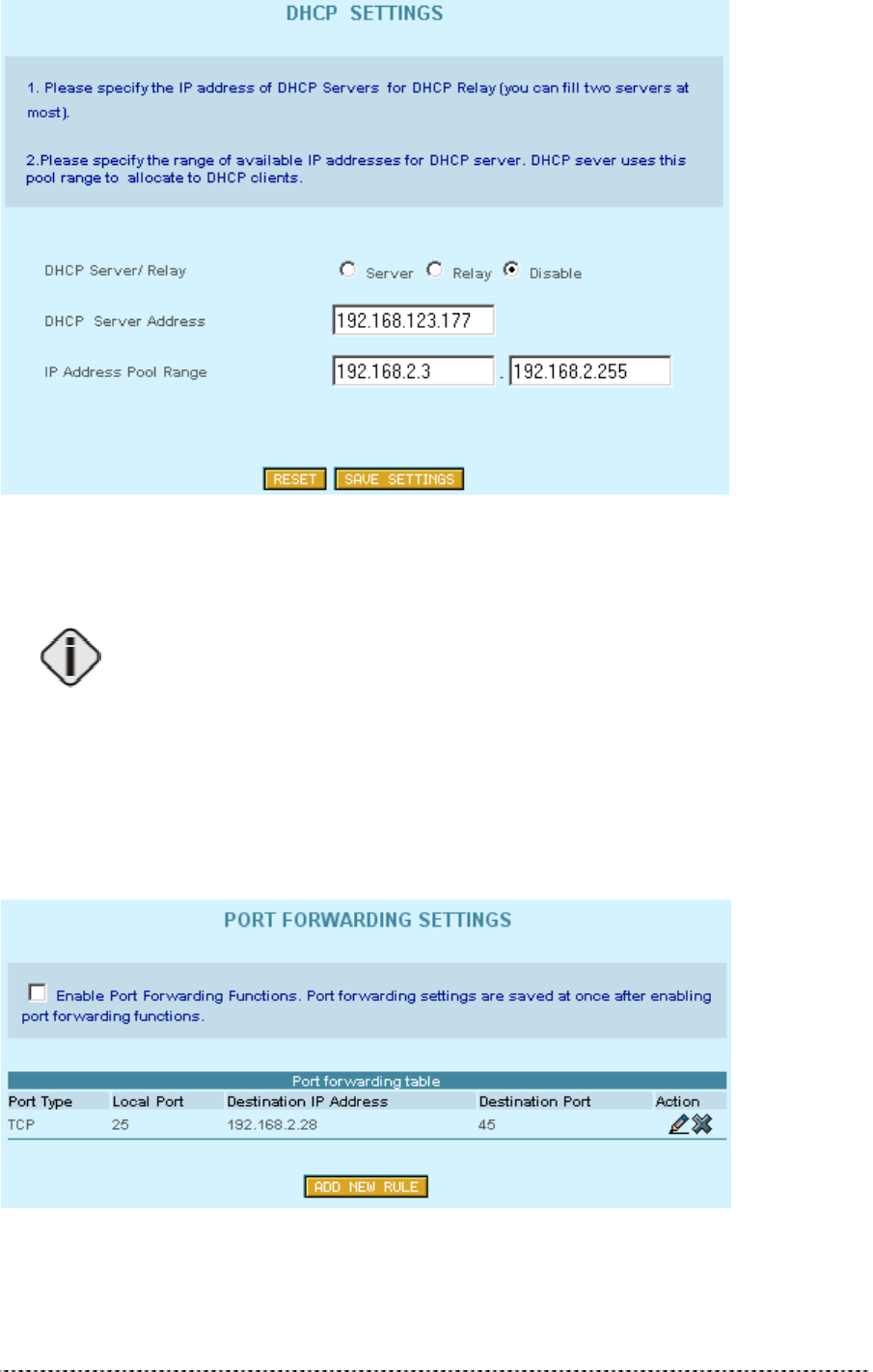
DHCP Settings
The DHCP server settings specify, which IP addresses are assigned to the DHCP clients in the LAN.
For a P-380 in AP router mode, these are the mobile wireless stations or P-380 devices in client
router mode with DHCP client function enabled.
Gemtek Systems Page 32
Figure 234 – DHCP Settings
Port Forwarding Settings
Port Forwarding Settings is available when the access point is in AP-Router
operation mode.
Port forwarding service provides access to computers in the LAN with dedicated services by
overriding the NAT (Network Address Translation) feature. Example of such services could be a web
server on a computer in the LAN, which should be open to public access for testing purposes. The
administrator can define the port of the application, which should be open to public access, the LAN
IP address of the computer running the service and a destination port, which is used in the router to
override the network address translation.
In the Port Forwarding Settings main page you can add, modify or delete forwarding rules.
Figure 245 -- Port Forwarding Settings
To specify a new port forwarding rule please click Add New Rule and insert the port type, the local
port, the destination IP address and the destination:
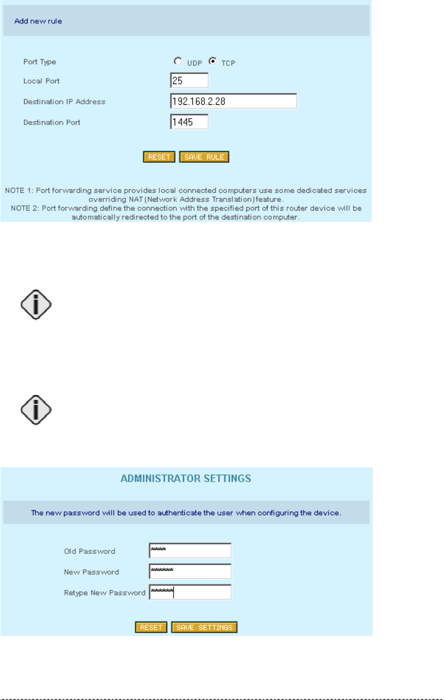
Gemtek Systems Page 33
Figure 256 – Add Port Forwarding Rule
In this example, all requests to the P-360 on port 25 will be redirected to the IP address 192.168.2.28
on port 1445.
Port forwarding is a kind of reverse function to IP masquerading. Hence this
function can take effect only when NAT is enabled! Please refer to your firewall
settings to check if the port forwarding settings are suitable.
Administrator’s Settings
You can change the Administrator’s password using this Administrator Settings menu.
Default Administrator password: Pass.
Just enter old administrator password, type new one (from 4 up to 16 characters) of your choice and
retype it. Click the Save Settings button to apply new administrators password to the system.
Figure 267 – Administrator’s Settings
Gemtek Systems Page 34
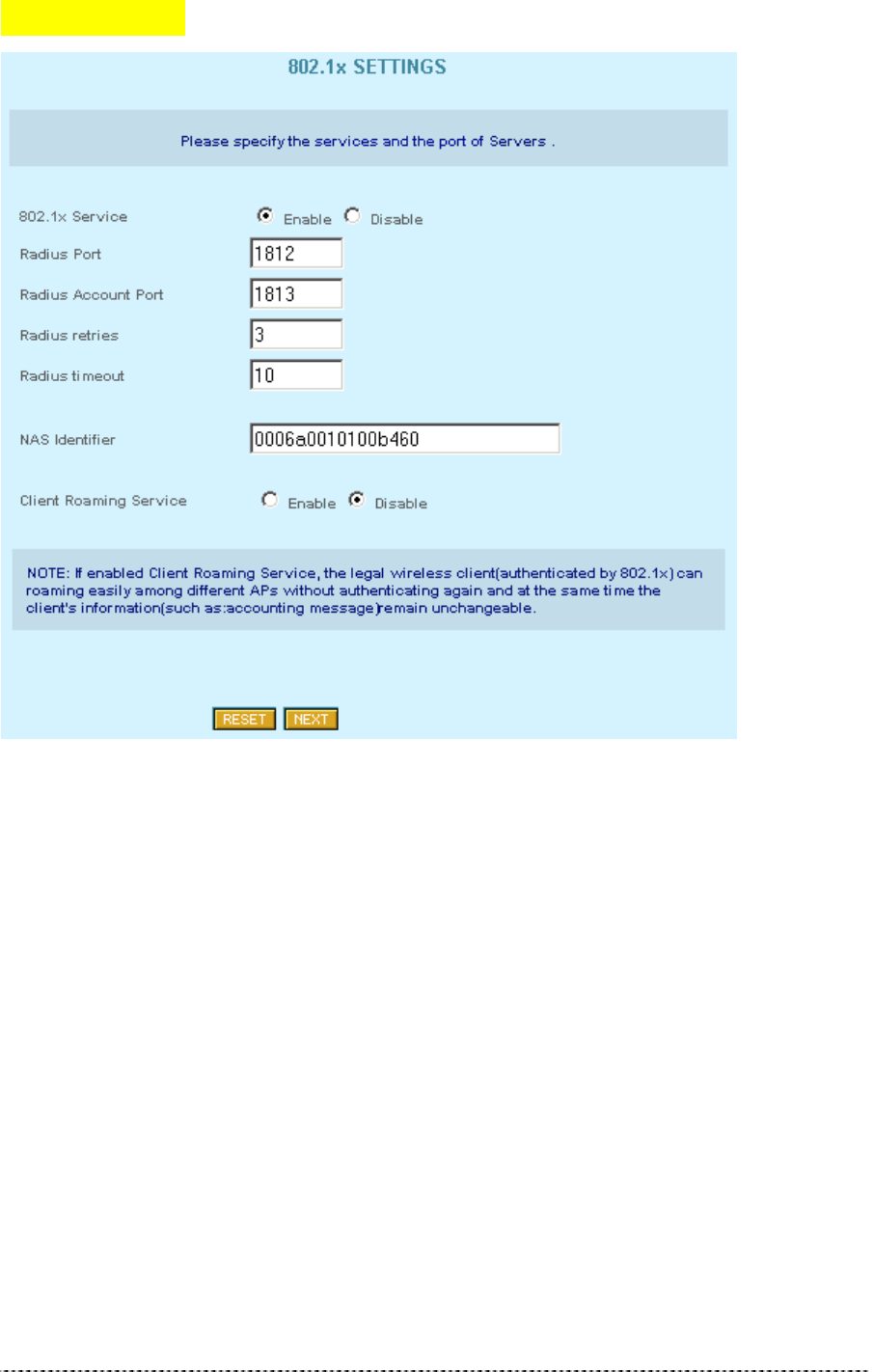
802.1x Settings
Figure 278 – 802.1x Settings (1)
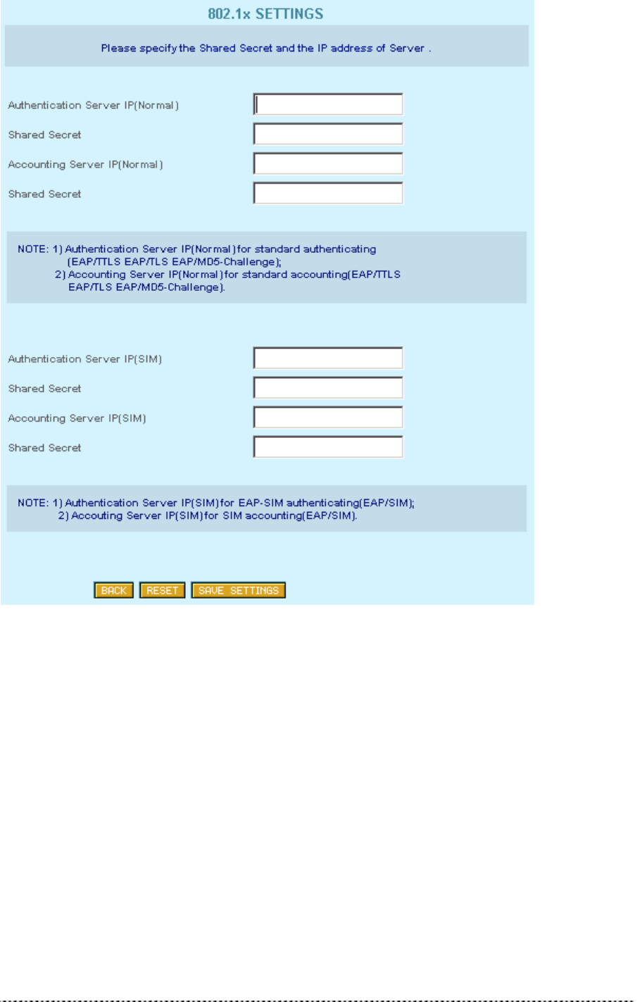
Gemtek Systems Page 35
Figure 29 – 802.1x Settings (2)
Gemtek Systems Page 36
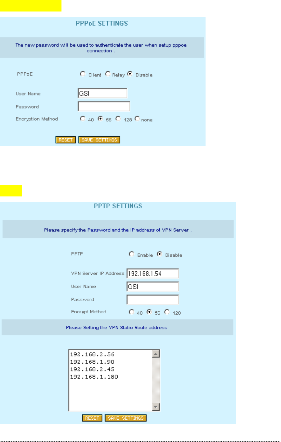
PPPoE Settings
Figure 280 -- PPPoE Settings
PPTP
Gemtek Systems Page 37
Figure 291 – PPTP Settings
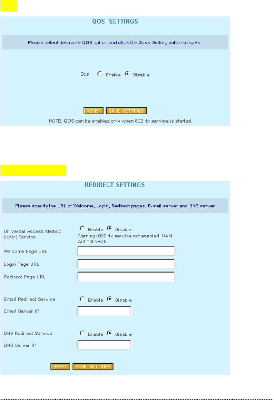
QoS
Figure 302 – QOS Settings
Redirect Settings
Figure 313 – Redirection Settings

Gemtek Systems Page 38
Load Balance
Figure 324 – Load Balance Settings

Gemtek Systems Page 39
System Tools
Using this menu you can perform system tests, configure SNMP settings, upgrade firmware, restart or
reset HiaB Access Point into factory defaults.
Clients
All clients currently connected to the P-360 Access Point is listed in the Connected Clients table. The
clients are listed by its MAC address.
Figure 335 – Connected Clients
Click the Refresh button if you want to renew the connected clients statistic.
Loopback Test
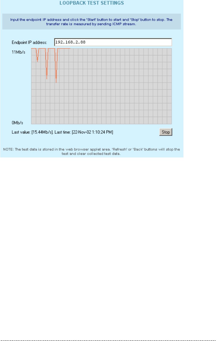
The loopback test is used for wireless link diagnostics. The loopback test graphically shows the data
transfer rate in Mb/s between the P-360 and a specified wireless network device. The transfer rate is
measured by sending an ICMP stream to the specific device. Data is refreshed every 10 seconds.
Gemtek Systems Page 40
Figure 346 – Loopback Test
To start the loopback test, do the following:
Endpoint IP – specify the device’s IP address, whose transfer rate needs to be measured.
Start – click to start measuring the specified wireless link.
The status line will show the last measured data transfer rate and the time when this data was
received from the wireless network device.
To stop loopback test simply click the Stop button.
SNMP Settings
SNMP (Simple Network Management Protocol) can be configured using the SNMP Settings. Several
Read-Only and Read-Write communities can be specified here. The Community strings are used for
SNMP authentication purposes. It is possible to allow or deny IP address groups from accessing the
P-360 using SNMP. To add new Read-Only or Read-Write community, click the Add New Rule next
to appropriate table.
Gemtek Systems Page 41
Figure 357 – SNMP Settings (1)
The following parameters should be entered to create new SNMP community:
Figure 368 – Add New SNMP Community
Community String – community name for (read-only/read-write) access.
Allow Community Access from IP – IP address/netmask for (read-only/read-write) community.
Allow Mib-view – specify MIB ???
IP address and netmask combination of 0.0.0.0/32 means “ANY” IP address can
connect. Access can be controlled for one specified IP (for example
192.168.2.100/32) or by a range (for example 192.168.2.0/24 for IP numbers
192.168.2.1 to 192.168.2.254).
xxxxxxxxxxxxxxxxxxxxxxxxxxxxxxxxxxxxxxxxxxxxxxxxxxxxxxxxxxxxxxxxxxxxxxxxxxxxxxxxxxxxxxxxxx
xxxxxxxx
Gemtek Systems Page 42
Figure 39 – SNMP Settings (2)
xxxxxxxxxxxxxxxxxxxxxxxxxxxxxxxxxxxxxxxxxxxxxxxxxxxxxxxxxxxxxxxxxxxxxxxxxxxxxxxxxxxxxxxxxx
xxxxxxxxxxxxxxxxxxxxxxxxxxxxxxxxxxx
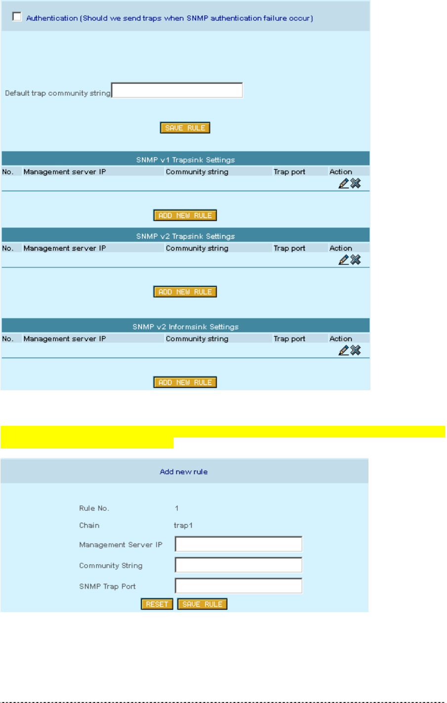
Figure 370 – Add SNMP Rule
Management Server IP ???
Community String ???

Gemtek Systems Page 43
SNMP Trap Port ???
Site Survey
The site survey test shows overview information for wireless networks in a local geography. Using this
test, users can scan for working access points, check their operating channels and see signal/noise
levels. To start the scan simply select the Site Survey menu.
Figure 381 – Site Survey
The available access points are listed in the table by MAC address and SSID. To refresh the statistics
click the Rescan button.
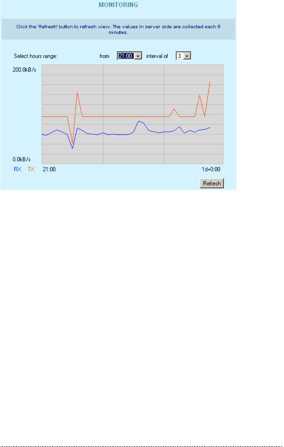
Monitoring
The Monitoring function shows Received/Transmitted bytes statistics per device.
These statistics show a five-minute average traffic rate over the last 24 hours period. RX (blue)
indicates incoming (Received) traffic and TX (red) indicates outgoing (Transmitted) traffic.
TX/RX monitoring is restarted on every reboot of the device. The reason is that the device has no real
time clock, so the time used is relative to the restart time. The first statistics appear as two points, five
minutes after the device has been restarted. A normal view is acquired 10 minutes after the P-360
reboots. First click the Show button to view the initial TX/RX statistics in the browser window. Click
the Refresh button instead of the Show button to get updated TX/RX statistics.
You can also change the TX/RX graph time interval. There are two drop-down menus used for this
purpose:
• The first one is used to choose the start hour of the interval. It is possible to choose any hour from
the last 24 hours (0-24), but the choice may be limited depending on the devices reboot time.
• The second drop-down is used to choose the time scale. The possible choices are from 0 to a
maximum of 23 hours.
For example: select time interval from 21 interval of 3 (time scale). Such selection shows graphic
starting from 21 hour after the device is started and up to 3 next hours. Following the same logic:
Select from 0 interval of 24 – full TX/RX graphic is displayed.
Selecting from 24 interval of 1 – the last hour TX/RX graphic is displayed.
Gemtek Systems Page 44
Figure 392 – Monitoring Test
RX – Received Kbytes per selected interval.
TX – Transmitted Kbytes per selected interval.
Upgrade
This function is used to update the current firmware version to a new one. If there is need to change
the firmware, a valid firmware file must be selected first by clicking the Browse button.
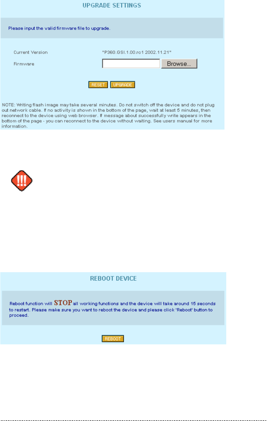
Gemtek Systems Page 45
Figure 403 – Upgrade Firmware
After selecting a valid firmware version file, click the Upgrade button to proceed. The upgrade
process begins.
Do not switch off and do not disconnect P-360 from power supply during firmware
update process because the device could be damaged. Best use Ethernet
connection (not wireless) for firmware update process.
After a successful upgrade process, the device firmware is upgraded, the Main Menu page is
displayed, and the previous device configuration set is maintained.
Reboot
Use the Reboot function to stop all working device functions and restart the device.
Figure 414 -- Reboot Device
Reboot – click the button to restart device.

Gemtek Systems Page 46
Reset Device
Figure 425 -- Reset Device to Defaults
Keep in mind that resetting the device is an irreversible process. The confirmation
message appears before starting the reset process. Read it carefully and confirm
as described. You must enter the administrator password to perform the reset
function. Please note that even the password will be set back to the factory default!
The device is restarted. All previous device configuration settings will be erased and the factory
default values applied. You can find the factory default values in the applendix.

Gemtek Systems Page 47
Introduction
CLISH (Command Line Interface Shell) software is a configuration shell for Wi-Fi “Hot-Spot in a Box”
Access Point device (P360). Using the CLISH interface the operator can:
configure all essential Wi-Fi “Hot-Spot in a Box” configuration settings;
show system and network statistics;
use system tools, such as Site Survey.
This manual describes the CLISH software command line interface and the command set available
from the shell.
Usage
CLISH is run by system on user login. This is done to prevent the manual modifying of configuration
files by users that do not know the system well enough. Such modifications can make other software
to function incorrectly thus disabling essential services. CLISH checks if arguments are correct and
only then modifies configuration settings.
The password for CLISH is the same as user’s system password. If user is not a ‘root’ user, he/she
will not be able to change settings, only to view them.
The Command Line Interface of CLISH does not take much getting used to. In key and key
combinations, it resembles the familiar interface of most common UNIX shells.
When the <TAB> key is pressed, the current word under the cursor is completed to full length, unless
if there are multiple possibilities. Pressing the question mark ‘?’ – will show content-sensitive help
about the available options. Other available key combinations in CLISH mode are listed in the table
bellow:
Command Line Interface Shell
Key and/or Combination Function
? Get context-sensitive help
<TAB> Complete the current keyword or list all the options
<CTRL> <D> Break out the subshell
<CTRL> <A> Jump to the beginning of the line
<CTRL> <E> Jump to the end of the line
<CursUP>/<CursDOWN> Scroll through the history of commands

Gemtek Systems Page 48
[Overview of all configuration interfaces, such as:
CLI
SMTP
HTTP
SSH
Description of all parameter/command of the configuration menu should be provided in this section.]
Reference Guide

Gemtek Systems Page 49

Gemtek Systems Page 50
[General hints, common problems, FAQ, technical support goes here.]
Troubleshooting

Gemtek Systems Page 51
Factory Default for P360 Access Point
The following settings and parameters are the factory default for “Hot-Spot in a Box” Access Point
model P360.
Default Device General Configuration Settings:
Operating Mode
Operation Mode AP (Access Point)
General Configuration Settings
Host Name P-360
DNS Server Address 0.0.0.0
System Identification identification
Serial Number MAC address of the device (provide on the device box)
Address address
Coordinates coordinates
Customer Name Customer_name
Network Configuration Settings
IP Address assigned by ISP 192.168.2.2
IP Subnet Mask 255.255.255.0
ISP Default Gateway (none)
DHCP Client disable
Wireless Configuration Settings
Access Point SSID P360
Domain World
Channel 11
Encryption Algorithm No Encryption
Antenna Gain in dBi 00 (can vary, depending on wireless LAN card)
Total Output Power (EIRP) in dBm 20 (can vary, depending on wireless LAN card)
Default Advanced Settings:
Firewall Settings
Firewall Function Not enabled
ACL
Default ACL Policy for wireless network Accept
Default ACL Policy for Ethernet Accept
Appendix

Gemtek Systems Page 52
Isolation
Isolation Disable
DHCP Server
DHCP Server/Relay Disable
DHCP Server Address 0.0.0.0
IP Address Pool Range 192.168.2.3-254
802.1x Settings
802.1x Service Disable
Radius Port 1812
Radius Account Port 1813
Radius Entries 3
Radius Timeout 10
NAS Identifier ????
Client Roaming Service Disable
PPPoE
PPPoE Disable
PPTP
PPTP Disable
VPN Server IP Address 0.0.0.0
User Name None
QOS
QOS Disable
Redirect Settings
Universal Access Method (UAM)
Service Disable
Email Redirect Service Disable
DNS Redirect Service Disable
Load Balance
Load Balance Disable
Balance level (1-5) 2
Broadcast Interval (10-300s) 50
Default System Tools Parameters:
SNMP
Read- Only Community String Public
Read-Write Community String Private

Gemtek Systems Page 53
[Glossary of the document is used to define terminology specific to the problem domain, explaining
terms, which may be unfamiliar to the reader.]
Glossary

Gemtek Systems Page 54
[Index of the document.]
Index

Gemtek Systems Page 55
Federal Communication Commission Interference
Statement
This equipment has been tested and found to comply with the limits for a Class B
digital device, pursuant to Part 15 of the FCC Rules. These limits are designed to
provide reasonable protection against harmful interference in a residential installation.
This equipment generates, uses and can radiate radio frequency energy and, if not
installed and used in accordance with the instructions, may cause harmful
interference to radio communications. However, there is no guarantee that
interference will not occur in a particular installation. If this equipment does cause
harmful interference to radio or television reception, which can be determined by
turning the equipment off and on, the user is encouraged to try to correct the
interference by one of the following measures:
- Reorient or relocate the receiving antenna.
- Increase the separation between the equipment and receiver.
- Connect the equipment into an outlet on a circuit different from that to which the
receiver is connected.
- Consult the dealer or an experienced radio/TV technician for help.
FCC Caution: To assure continued compliance, any changes or modifications not
expressly approved by the party responsible for compliance could void the user's
authority to operate this equipment.
This device complies with Part 15 of the FCC Rules. Operation is subject to the
following two conditions: (1) This device may not cause harmful interference, and (2)
this device must accept any interference received, including interference that may
cause undesired operation.
IMPORTANT NOTE:
FCC Radiation Exposure Statement:
This equipment complies with FCC radiation exposure limits set forth for an
uncontrolled environment. This equipment should be installed and operated with
minimum distance 20cm between the radiator & your body.
This transmitter must not be co-located or operating in conjunction with any other
antenna or transmitter.