GemTek Technology A950806AG Dual Radio 2.4GHz/5GHz Access Point User Manual BW1250 UG EN Revised
Gemtek Technology Co., Ltd. Dual Radio 2.4GHz/5GHz Access Point BW1250 UG EN Revised
Manual

0 72 0
Copyright©2006 BROWAN Communications Inc
BW1250
Dual Radio 2.4GHz/5GHz Access Point
www.browan.com
User
’
s Guide V1.0

Browan Page 1 of 68
Copyright
© 2002-2006 BROWAN COMMUNICATIONS
This product plan and the software described in it are copyrighted with all rights reserved. No part of
this publication may be reproduced, transmitted, transcribed, stored in a retrieval system, or translated
into any language in any form by any means without the written permission of BROWAN
COMMUNICATIONS.
Notice
BROWAN COMMUNICATIONS reserves the right to change specifications without prior notice.
While the information in this document has been compiled with great care, it may not be deemed an
assurance of product characteristics. BROWAN COMMUNICATIONS shall be liable only to the
degree specified in the terms of sale and delivery.
The reproduction and distribution of the documentation and software supplied with this product and
the use of its contents is subject to written authorization from BROWAN COMMUNICATIONS.
Trademarks
The product described in this book is a licensed product of BROWAN.

Browan Page 2 of 68
Within the 5.15 to 5.25 GHz band (5GHz radio channels 34 to 48) the U-NII devices
are restricted to indoor operations to reduce any potential harmful interference to
MSS operations.
FCC Warning
FCC Interference Statement
This equipment has been tested and found to comply with the limits for a Class B digital device,
pursuant to Part 15 of the FCC Rules. These limits are designed to provide reasonable protection
against harmful interference in a residential installation. This equipment generates, uses and can
radiate radio frequency energy and, if not installed and used in accordance with the instructions, may
cause harmful interference to radio communications. However, there is no guarantee that interference
will not occur in a particular installation. If this equipment does cause harmful interference to radio or
television reception, which can be determined by turning the equipment off and on, the user is
encouraged to try to correct the interference by one of the following measures:
Reorient or relocate the receiving antenna.
Increase the separation between the equipment and receiver.
Connect the equipment into an outlet on a circuit different from that to which the receiver is
connected.
Consult the dealer or an experienced radio/TV technician for help.
This device complies with Part 15 of the FCC Rules. Operation is subject to the following two
conditions: (1) This device may not cause harmful interference, and (2) this device must accept any
interference received, including interference that may cause undesired operation.
FCC Caution
Any changes or modifications not expressly approved by the party responsible for compliance could
void the user's authority to operate this equipment.
FCC Radiation Exposure Statement
This equipment complies with FCC radiation exposure limits set forth for an uncontrolled environment.
This equipment should be installed and operated with minimum distance 20cm between the radiator &
your body.
If this device is going to be operated in 5.15 ~ 5.25GHz frequency range, then it is restricted in indoor
environment only.
This transmitter must not be co-located or operating in conjunction with any other antenna or
transmitter.
The availability of some specific channels and/or operational frequency bands are
country dependent and are firmware programmed at the factory to match the intended
destination. The firmware setting is not accessible by the end user.

BW1250 Sep. 22, 2006
Browan Page 3 of 68
COPYRIGHT ........................................................................................................................................... 1
NOTICE................................................................................................................................................... 1
TRADEMARKS....................................................................................................................................... 1
FCC Warning.......................................................................................................................................2
CONTENTS............................................................................................................................................. 3
ABOUT THIS GUIDE.............................................................................................................................. 5
Purpose ............................................................................................................................................... 5
Prerequisite Skills and Knowledge......................................................................................................5
Conventions Used in this Document ................................................................................................... 5
Help Us to Improve this Document! .................................................................................................... 5
BROWAN Technical Support ..............................................................................................................5
CHAPTER 1 – INTRODUCTION ............................................................................................................ 6
Product Overview ................................................................................................................................ 6
Features Highlight ............................................................................................................................... 7
CHAPTER 2 - INSTALLATION .............................................................................................................. 9
The Product Package..........................................................................................................................9
Hardware Introduction .........................................................................................................................9
General Overview ............................................................................................................................9
Bottom Cover .................................................................................................................................10
LEDs ..............................................................................................................................................10
Connectors.....................................................................................................................................11
Connect to the Power Source and Local Network ............................................................................12
Software Installation ..........................................................................................................................13
Initialization ....................................................................................................................................13
Software Introduction: KickStart ....................................................................................................13
Access Your BW1250....................................................................................................................13
CHAPTER 3 – APPLICATION MODE ................................................................................................. 17
AP + AP Mode...................................................................................................................................17
AP + Bridge Mode .............................................................................................................................17
CHAPTER 4 – REFERENCE MANUAL............................................................................................... 19
Web Interface....................................................................................................................................19
Status ................................................................................................................................................20
Status | Device Status....................................................................................................................20
Status | Wireless Status.................................................................................................................21
Status | Interface Statistics ............................................................................................................22
Network .............................................................................................................................................23
Network | Interface.........................................................................................................................23
Network | RADIUS Server .............................................................................................................25
Network | DHCP Settings ..............................................................................................................27
Network | NTP Settings .................................................................................................................32
Network | Time Settings.................................................................................................................34
Wireless.............................................................................................................................................35
Wireless | Basic .............................................................................................................................35
Wireless | Advance ........................................................................................................................44
Wireless | WEP ..............................................................................................................................52
Contents

BW1250 Sep. 22, 2006
Browan Page 4 of 68
Wireless | MAC ACL ......................................................................................................................53
System...............................................................................................................................................56
System | Security ...........................................................................................................................56
System | SNMP..............................................................................................................................57
System | Telnet ..............................................................................................................................58
System | Configuration ..................................................................................................................58
System | Reset...............................................................................................................................60
System | Upgrade ..........................................................................................................................61
APPENDIX ............................................................................................................................................ 63
A) Specification .................................................................................................................................63
B) Factory Defaults for the BW1250 .................................................................................................65
C) Regulatory Domain/Channels/Power ........................................................................................... 66
D) Location ID and ISO Country Codes ............................................................................................68

BW1250 Sep. 22, 2006
Browan Page 5 of 68
Purpose
This document provides information and procedures on hardware installation, setup, configuration,
and management of the BROWAN high performance Dual Radio 2.4GHz/5GHz AP BW1250.
Prerequisite Skills and Knowledge
To use this document effectively, you should have a working knowledge of Local Area Networking
(LAN) concepts and wireless Internet access infrastructures. In addition, you should be familiar with
the following:
Hardware installers should have a working knowledge of basic electronics and mechanical
assembly, and should understand related local building codes.
Network administrators should have a solid understanding of software installation procedures for
network operating systems under Microsoft Windows 95, 98, Millennium, 2000, NT, and Windows
XP and general networking operations and troubleshooting knowledge.
Conventions Used in this Document
The following typographic conventions and symbols are used throughout this document:
Very important information. Failure to observe this may result in damage.
Important information that should be observed.
Additional information that may be helpful but which is not required.
bold Menu commands, buttons and input fields are displayed in bold
code File names, directory names, form names, and system-generated output
such as error messages are displayed in constant-width type
<value> Placeholder for certain values, e.g. user inputs
[value] Input field format, limitations, and/or restrictions.
Help Us to Improve this Document!
If you should encounter mistakes in this document or want to provide comments to improve the
manual please send e-mail directly to:
manuals@browan.com
BROWAN Technical Support
If you encounter problems when installing or using this product, please consult the BROWAN website
at www.browan.com for:
Direct contact to the BROWAN support centers.
Frequently Asked Questions (FAQ).
Download area for the latest software, user documentation and product updates.
About this Guide

BW1250 Sep. 22, 2006
Browan Page 6 of 68
Thank you for choosing the BROWAN Dual Radio Access Point BW1250.
The BROWAN BW1250 operates simultaneously in both 5 GHz and 2.4 GHz frequency band and is
fully compliant to 802.11b/g and 802.11a standard with its high performance and enhanced security.
The two Dual-Band radio (a/g + a/g) feature supplies the furthest in flexibility and makes sure low
interference and large coverage. The a+g operation mode and Multiple BSSID that this product
provides differentiates it from traditional indoor AP product.
Product Overview
Flexibility and High performance
BROWAN BW1250 is built as a high-performance and feature-rich indoor Access Point. With two
dual-band radios operating AP, Bridge and Repeater working modes can provide the furthest flexible
wireless network deployment:
Simultaneously supports 802.11a/b/g in one platform
Dual AP configuration for high client density environment
Dual AP configuration for supporting all kinds of client (11a/b/g) simultaneously
Mix of AP and Bridge configuration for enhancing wireless coverage by wireless repeating and
wireless bridging
Secure and Reliable Wireless Networking
BROWAN’s BW1250 supports and meets all security requirement of wide area networking
professionals for secured wireless network:
Supports VLAN, up to 16 VLAN ID per Radio
IEEE 802.1x/EAP with password, certificates and SIM card (EAP/TLS, EAP/PEAP, EAP/SIM
and EAP/TTLS)
64bits/128bits static and dynamic WEP key
Support Wi-Fi protected Access (WPA/WPA2) with AES and TKIP
Layer 2 Isolation for preventing snooping on the same radio
MAC ACL for preventing illegal attacking from Internet
Hidden SSID broadcast to prevent illegal users connection
Strong Anti-interference
Dynamic Channel Allocation (DCA) solution automatically selects optimal operational frequency
channel during power up and periodically monitors the environment and adjusts for best operational
channel.
Multiple BSSID
Support up to 16 BSSID per radio and each can be configured independently to support defferent
range of security policy, authentication methods, RADIUS servers and VLAN IDs. Each BSSID can be
Chapter 1 – Introduction
* * Two radios are under firmware controlled not to use the same channel or a channel which are separated less than 4 channels and
is not user changeable.

BW1250 Sep. 22, 2006
Browan Page 7 of 68
set by its priority on a basis of 802.1p tag or 802.11e EDCA which enables WLAN client device to
access wireless link QoS capabilities.
Simple Installation
Support IEEE 802.3af Power-over-Ethernet as well as external power supply by power adaptor. This
reduces the cost and the effort of installation and maintenance dramatically.
Easy Remote Management and Maintenance
BROWAN’s BW1250 supports remote management with HTTPS, CLISH and SNMP:
Web-based user interface with HTTPS request and CLISH configuration with SSHv2 request
supplies a secure remote management
BROWAN’s Network Management System supplies the system management solution
DHCP Server/DHCP Relay/DHCP Client service supplies flexibility for different network setup
Remote software upgrading via HTTPs
Management Option
You can use the Access Point management systems through the following interfaces:
Web-browser interface
with HTTPS
Command Line interface (CLI) with optional SSH
Simple Network Management Protocol
This user’s guide provides detailed description of the management for the web-browser interface.
Features Highlight
Super AP
Multiple BSSID (up to 16)
SSID per BSSID
Enabled or Disabled Hidden SSID per BSSID
VLAN ID per BSSID
QoS priority per BSSID based on 802.1p or EDCA
AAA way per BSSID, 802.1x and web login
Co-existence of 802.1x and web login
Security policy per BSSID
WPA pass-through
RADIUS server per BSSID
Traffic priority per BSSID
AAA
RADIUS client supporting
802.1x supporting(EAP/TLS,EAP/TTLS, EAP/PEAP and EAP/SIM)
Accounting supporting (RFC 2866)
Security

BW1250 Sep. 22, 2006
Browan Page 8 of 68
Static 64/128bits WEP, Dynamic 64/128bits WEP
WPA/TKIP and WPA/AES support
MAC ACL
Access Control (accept rule and deny rule) based on MAC address
Layer 2 Isolation
Hidden SSID
Management
Secure management via HTTPS, CLISH, SNMP
Standard MIB and BROWAN Private MIB
BROWAN NMS Support
Detail Client Survey
Network interface statistics
Remote firmware update via WEB UI
Backup/Restore configuration file
DHCP Server
Kickstart Tool
Bridge/Client Diagnostic tool
NTP support and setting time manually
Maintenance
Software watchdog
Super Brige
802.11a/b/g compliant
108Mbps raw data rate supporting
Up to 8 bridge links supporting
Special radio for Bridge
WPA/PSK over Bridge link
BW1250 Sep. 22, 2006
Browan Page 9 of 68
This chapter provides installation instructions for the hardware and software components of the
Access Point BW1250. It also includes the procedures for the following tasks:
Hardware Introduction (LEDs, Connectors)
Connecting the Access Point
Software Installation
The Product Package
The product deliverables:
BW1250 Dual Radio 2.4GHz/5GHz Access Point
Ethernet cable,1.5m
USA type Power Cord
EU type Power Cord
External power supply
Installation CD containing:
BW1250 User’s Guide in PDF format
KickStart Utility
Bridge/Client Diagnostic Utility
Product Firmware
Release Notes
Adobe Acrobat Readers
Release Notes
Printed 3 Year Warranty Card
If any of these items are missing or damaged, please contact your reseller or
BROWAN sales representative.
Hardware Introduction
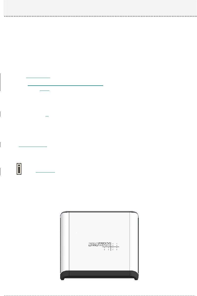
General Overview
Figure 1 – BW1250 General View
Chapter 2 - Installation
BW1250 Sep. 22, 2006
Browan Page 10 of 68
The front panel of BW1250 contains:
There are 4 indicator lights (LEDs) that help to describe the state of various networking and
connection operations.
The Bottom cover of BW1250 contains:
Connectors which enable you to make different network connections for the device
Reset button enables you to reboot or reset the device configuration to the factory defaults
Press the Reset button for less than 5 seconds to reboot the device.
Press the Reset button for more than 5 seconds to set the device to factory
defaults.
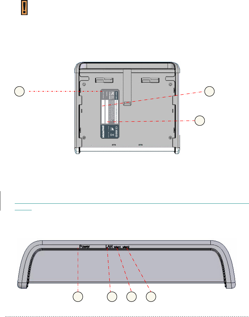
Bottom Cover
Figure 2 –Bottom Cover of the BW1250
The Bottom Cover of the BW1250 contains:
1. Back Label with Model and Device name. The official device name is Dual Radio 2.4GHz/5GHz
Access Point, model BW1250.
2. Serial Number label of the device.
3. MAC address label of the device. The MAC label shows the WLAN1 interface MAC address of the
device.
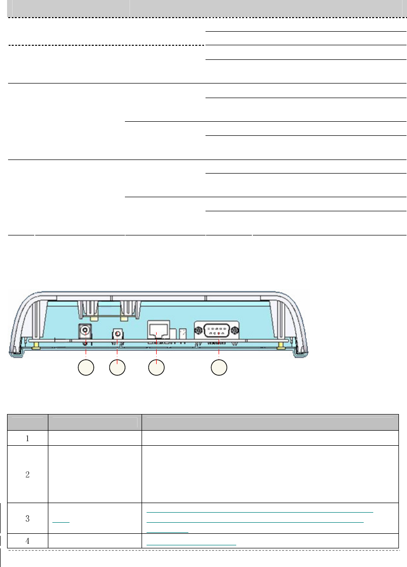
LEDs
The BW1250 Access Point has 4 LEDs located on the front panel:
2
1
3
1
2
3
4
BW1250 Sep. 22, 2006
Browan Page 11 of 68
Figure 3 – LEDs of the BW1250
The various states of the LEDs indicate different networking and connection operations as follows:
Item
LED Color Status Indication
On BW1250 is active/working 1 Power Green
Blink BW1250 is booting
On BW1250 Ethernet Port Link Active 2 LAN Green
Blink BW1250 Ethernet Port is
Transmitting and Receiving data
On BW1250 WLAN1 RF card Active Green
(802.11g module
is functional) Blink BW1250 WLAN1 RF card is
Transmitting and Receiving data
On BW1250 WLAN1 RF card Active
3 Wireless1
Amber
(802.11a module
is functional) Blink BW1250 WLAN1 RF card is
Transmitting and Receiving data
On BW1250 WLAN2 RF card Active Green
(802.11g module
is functional) Blink BW1250 WLAN2 RF card is
Transmitting and Receiving data
On BW1250 WLAN2 RF card Active
4 Wireless2
Amber
(802.11a module
is functional) Blink BW1250 WLAN2 RF card is
Transmitting and Receiving data
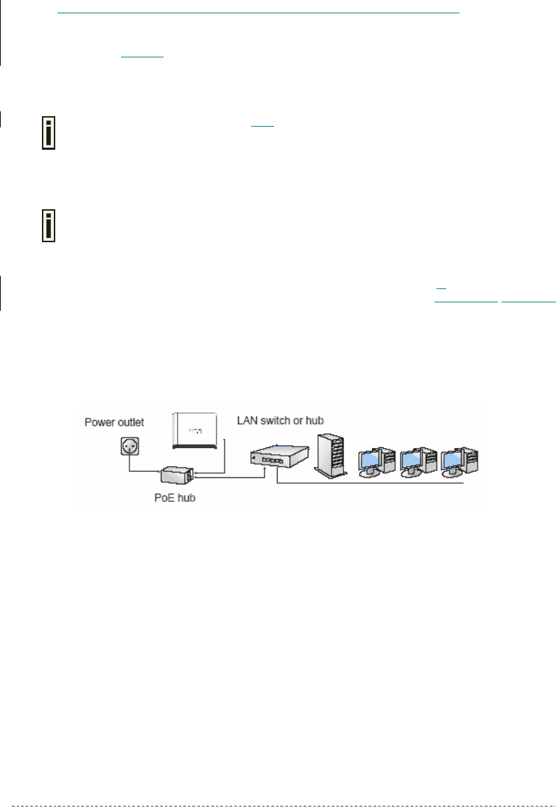
Connectors
The BW1250 has several connectors on the rear panel:
Figure 4 –RF Connectors
Descriptions of the connectors are given in the following table:
Item Connector Description
Power Jack For power supply
Reset button
Reboot or reset to factory defaults.
Press the reset bottom for less than 5 seconds to reboot the
Access Point. Press the reset bottom for more than 5 seconds
to reset the Access Point to factory defaults
LAN
Connect to the RJ45 port of your laptop for configuration or
connect to the PoE device for power supply and network
connection
Console For console connection
4
1
2
3
BW1250 Sep. 22, 2006
Browan Page 12 of 68
Connect to the Power Source and Local Network
BW1250 can be powered on by connecting to either one of the following two device:
♦ Power-over-Ethernet
♦ External Power Adapter
Case 1 Use the Power-over-Ethernet:
Use the enclosed power cord and any IEEE802.3af Compliant POE Power Source
Devices to supply your BW1250 Access Point.
Step 1 Place the Access Point on a flat work surface or hang on the wall.
Use the enclosed 4 screws to put the rear side of the Access Point hanging on the
wall.
Step 2 Connect the Ethernet cable from the BW1250 route to an IEEE802.3af compliant Power
source Equipment, Such as BE3011 POE HUB, E-820 POE Switch products of BROWAN.
Step 3 If you use the BE3011 POE HUB, please connect the BW1250 LAN port to the PWR-LAN
OUT port of BE3011 and connect the BE3011 LAN-IN port to the Switch or hub in the
local network.
Figure 5 – Connect BW1250 to Power source and network by PoE HUB
Case 2 Use External Power Adapter
Step 1 Place the Access Point on a flat work surface or hang on the wall.
Step 2 Use the enclosed Ethernet cable to connect the LAN port of the Access Point to the Switch
or hub in the local network.
Step 3 Connect the power supply to the Access Point.

BW1250 Sep. 22, 2006
Browan Page 13 of 68
Software Installation
Initialization
There are two choices for the first web browser connection to your BW1250: either enter the
BW1250's IP address and subnet (default networks settings) into the browser or launch the KickStart
utility that is provided with your product CD.
The default network settings for your new access point are:
LAN port: IP 192.168.2.2 subnet 255.255.255.0
Software Introduction: KickStart
The BROWAN KickStart is a software utility that is included on the Installation CD.
The utility automatically detects access points or access controllers installed on your network,
regardless of its host IP address and lets you configure each unit’s IP settings. The feature list for the
KickStart utility is listed below:
Scanning your subnet for all connected APs, ACs
Quick access to your AP via HTTPS, telnet, SSH
To install the KickStart utility insert the Installation CD into your CD-ROM drive. Find and install the
utility from the product CD into the computer.
Access Your BW1250
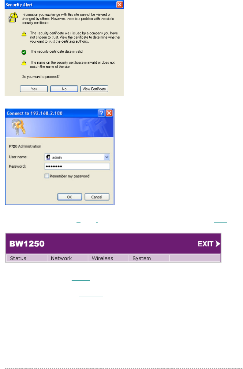
There are two choices for the first Web browser connection to your BW1250:
Use the Web browser.
Launch the KickStart utility that can be found in your product CD.
If first method is preferred, please follow these instructions:
Step 1 Configure your PC with a static IP address on the 192.168.2.0 subnet with mask
255.255.255.0. Connect the BW1250 to the same physical network as your PC.
Connect the BW1250 by typing the default IP of the BW1250 into the Web browser
address bar:
https://192.168.2.2
Step 2 Enter the BW1250 administrator login credential to access the Web management page.
The default administrator log on settings for all access point interfaces are:
User Name: admin
Password: admin01
If the Installation CD does not start automatically, please run “autorun.exe”
manually from the root directory of the installation CD.
BW1250 Sep. 22, 2006
Browan Page 14 of 68
Step 3 After successfully log on, you will see the main page of the BW1250’s Web user
interface:
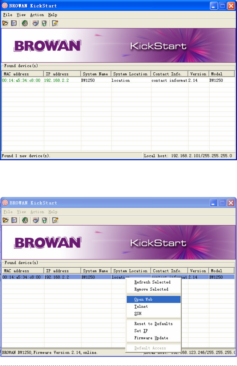
If second method is prefered, please follow the instructions:
Step 1 Install the KickStart utility that can be found in the product CD. Click Start >
Programs > BROWAN > KickStart to launch the application. If the BW1250
device is connected to your network, the utility will automatically find your BW1250:
BW1250 Sep. 22, 2006
Browan Page 15 of 68
Step 2 Select your controller and right click. Select Open WEB item to launch the web
management interface through the secure https connection:

BW1250 Sep. 22, 2006
Browan Page 16 of 68
Step 3 Enter the BW1250 administrator login credential to access the web management
interface.
The default administrator log on settings for all access point interfaces are:
User name: admin
Password: admin01
Step 4 After successfully log on, you will see the web interface.
BW1250 Sep. 22, 2006
Browan Page 17 of 68
The two Dual-Band radios (a/g + a/g) supply the furthest flexible application. Three application modes
are supplied by BW1250:
AP + AP mode
AP + Bridge mode
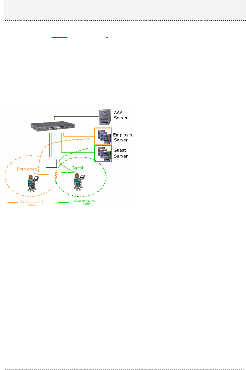
AP + AP Mode
AP + AP configuration can be for client density environment.
The typical usage that is recommended is: 11g AP + 11a AP.
Figure 6 – AP +AP application mode
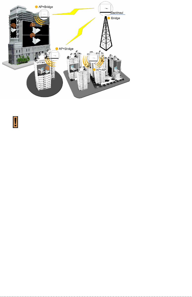
AP + Bridge Mode
AP + Bridge configuration is for environment with last mile issue.
The typical usage that is recommended is: 11g AP + 11a Bridge.
Chapter 3 – Application Mode
BW1250 Sep. 22, 2006
Browan Page 18 of 68
Figure 7 – AP +Bridge application mode
Because of the reason of the antenna interference, the performance will deteriorate
dramatically if the same band (2.4GHz or 5GHz) is used both on the two RF
modules. It is strongly recommended that one RF module uses 2.4GHz and the
other uses 5GHz.
BW1250 Sep. 22, 2006
Browan Page 19 of 68
This chapter contains web management reference information.
The web management main menu consists of the following sub menus:
Status – device status showing
Network – device settings affecting networking
Wireless – device settings related to the wireless part of the BW1250
System – device system settings directly applicable to the BW1250
Exit – click exit and leave the web management then close your web-browser window.
Web Interface
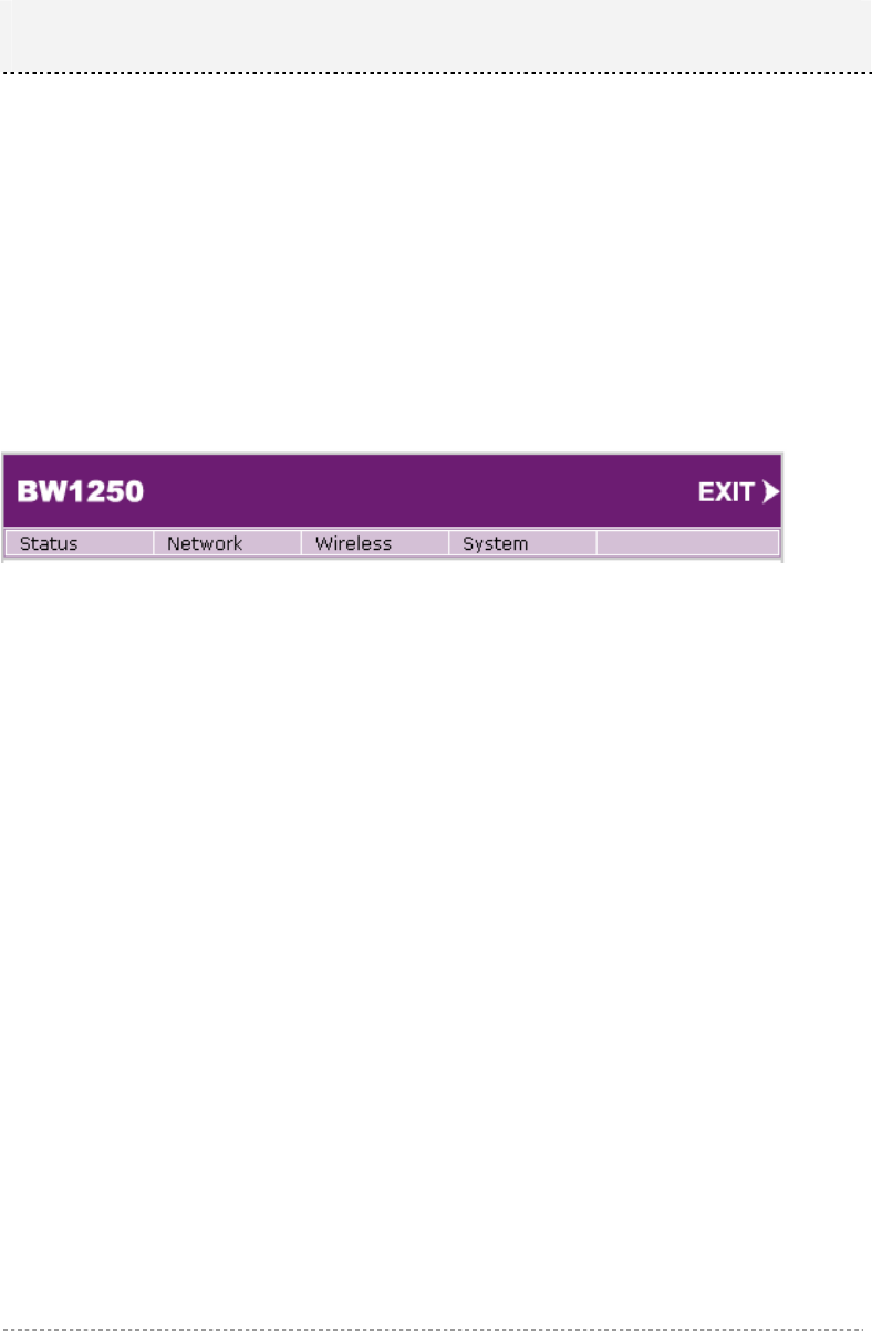
The main web management menu is displayed at the top of the page after successfully logging into
the system (see the figure below). From this menu all essential configuration pages are accessed.
Figure 8 – Main Configuration Management Menu
The web management menu has the following structure:
Status
Device Status – show the status related with the whole device
Wireless Status – show the status of the two radios
Interface Statistics – show the status of each network interface
Network
Interface – TCP/IP settings of BW1250 LAN (Bridge) port
RADIUS Server – specify the settings of RADIUS server which is used by 802.1x or WPA
DHCP Settings– specify the settings of DHCP server or DHCP relay service
NTP Settings – NTP settings of BW1250
Time Settings – Manually set time
Wireless
Basic – specify the basic settings related with wireless part
Advance – specify the settings of multiple BSSID or Bridge
WEP – specify the WEP settings related with static WEP encryption
MAC ACL – MAC ACL settings for BW1250
System
Security – set access permission to your BW1250
SNMP – SNMP service
Telnet – Telnet/SSH service
Configuration – system configuration utilities, including Backup/Upload configuration
Chapter 4 – Reference Manual
BW1250 Sep. 22, 2006
Browan Page 20 of 68
Reset – reboot device and restore systems to factory default
Upgrade – Upgrade the firmware remotely
In the following sections, short references for all menu items are presented.
Status
Status | Device Status
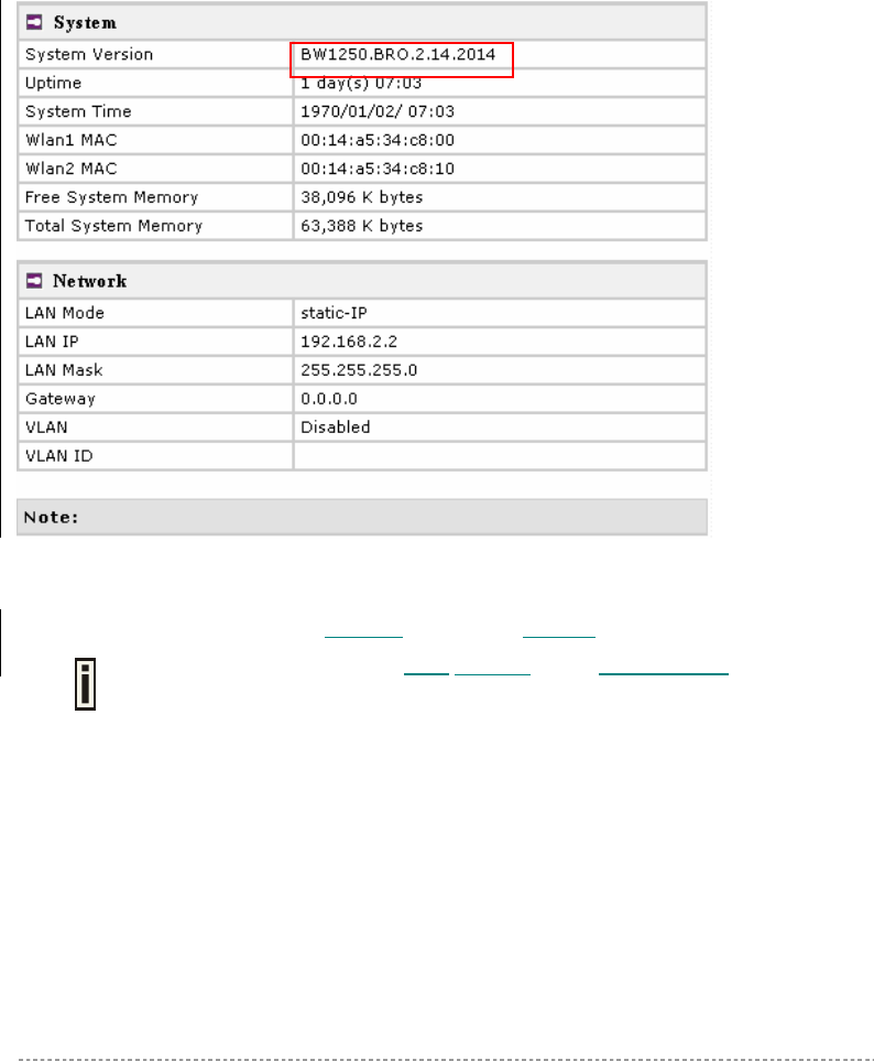
The device status page shows important information for the BW1250, its system status and network
configuration.
Figure 9 – Device Status
System Version display the current firmware version of the BW1250
This is important information when seeking support from BROWAN and preparing
firmware upgrading
Uptime – indicates the time, expressed in days, hours and minutes since the system was last
rebooted.
System Time – shows the current time of the BW1250.
Wlan1 MAC / Wlan2 MAC – shows the MAC addresses of the two wireless interfaces of the BW1250
Free System Memory – indicates the memory currently available in the BW1250
Total System Memory – indicates the total memory in the BW1250
LAN Mode – indicate static IP or DHCP client is used for BW1250 LAN IP address
LAN IP – shows the LAN IP address of BW1250
LAN Mask – shows the LAN Network Mask of BW1250
Gateway – shows the default gateway of BW1250
BW1250 Sep. 22, 2006
Browan Page 21 of 68
VLAN –specify whether to manage this device via VLAN.
VLAN ID _ specify VLAN ID when managing this device via VLAN.
Status | Wireless Status
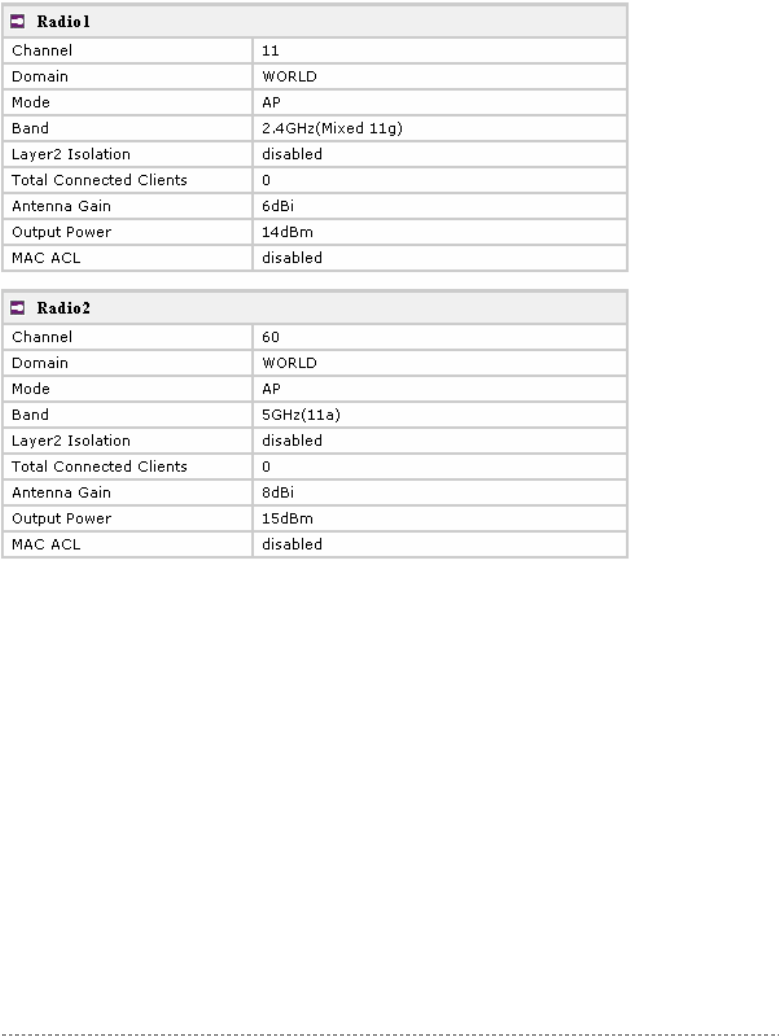
The wireless status shows the information related with BW1250 two wireless interfaces.
Figure 10 – Wireless Status
Radio1 / Radio2 – relates with two wireless interfaces
Channel – indicates which channel is in use.
Domain – indicates regulatory domain set on the BW1250
Mode – AP or Bridge mode is be used for this wireless interface
Band – specify which band is in use for wireless interface
Layer2 Isolation – specify the status of Layer2 Isolation service on this wireless interface
Total Connected Clients – indicates number of the currently connected clients to your BW1250
Antenna Gain – indicates antenna Gain value.
Output Power - indicates output power of the RF card, not including antenna gain.
MAC ACL – indicates the status of MAC ACL feature on BW1250
19
18

BW1250 Sep. 22, 2006
Browan Page 22 of 68
Status | Interface Statistics
The Interface Statistics shows each network interface status, including Input / Output bytes, packets
or error.
Figure 11 – Interface Statistics
Interface Name – shows the name of each network interface, where ixp0 is related to LAN interface,
wlan1_x is related to WLAN1 sub-interface and wlan2_x is related to WLAN2 sub-interface.
Input Bytes (KB) – shows the total number of bytes received on the network interface. The bytes
number is displayed in KB.
Input Packets – shows the packets number received on the network interface.
Input Errors – shows the packets number which contain errors preventing them from being received
correctly.
Output Bytes (KB) – shows the total number of bytes transmitted out of the network interface. The
bytes number is displayed in KB.
Output Packets – shows the packets number transmitted out of the network interface.
Output Errors – shows the packets number which contain errors preventing them from being
transmitted out correctly.
Refresh – gets the updated network interface information.
BW1250 Sep. 22, 2006
Browan Page 23 of 68
Network
Network | Interface
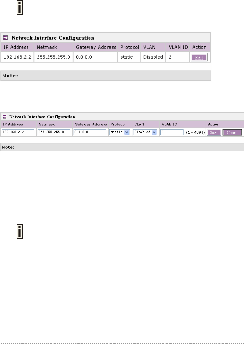
The interface configured is bridge device therefore only one interface is displayed
here for configuration.
Bridge interface and its settings are listed in the Interface page.
Figure 12 – Interface Configuration Table
To change network interface (bridge) configuration properties click the Edit button in the Action
column. The status can be changed now:
Figure 13 – Edit Interface Configuration Settings
IP Address – specify new interface IP address [in digits and dots notation, e.g. 192.168.123.70].
Netmask – specify the subnet mask [[0-255].[0-255].[0-255].[0-255]].These numbers are a binary
mask of the IP address, which defines IP address order and the number of IP addresses in the subnet.
Gateway Address – interface gateway. For Bridge type interfaces, the gateway is always the
gateway router.
Protocol – specify static for setting IP address manually and dhcp for getting IP address dynamically
acting as DHCP client.
When dhcp is used for getting IP address, Kickstart is strongly recommended to
find your device.
VLAN - specify whether to manage this device via VLAN.
VLAN ID _ specify VLAN ID when managing this device via VLAN.
Save – save the entered values.
Cancel – restore all previous values.
Change status or leave in the default state if no editing is necessary and click the Save button.
BW1250 Sep. 22, 2006
Browan Page 24 of 68
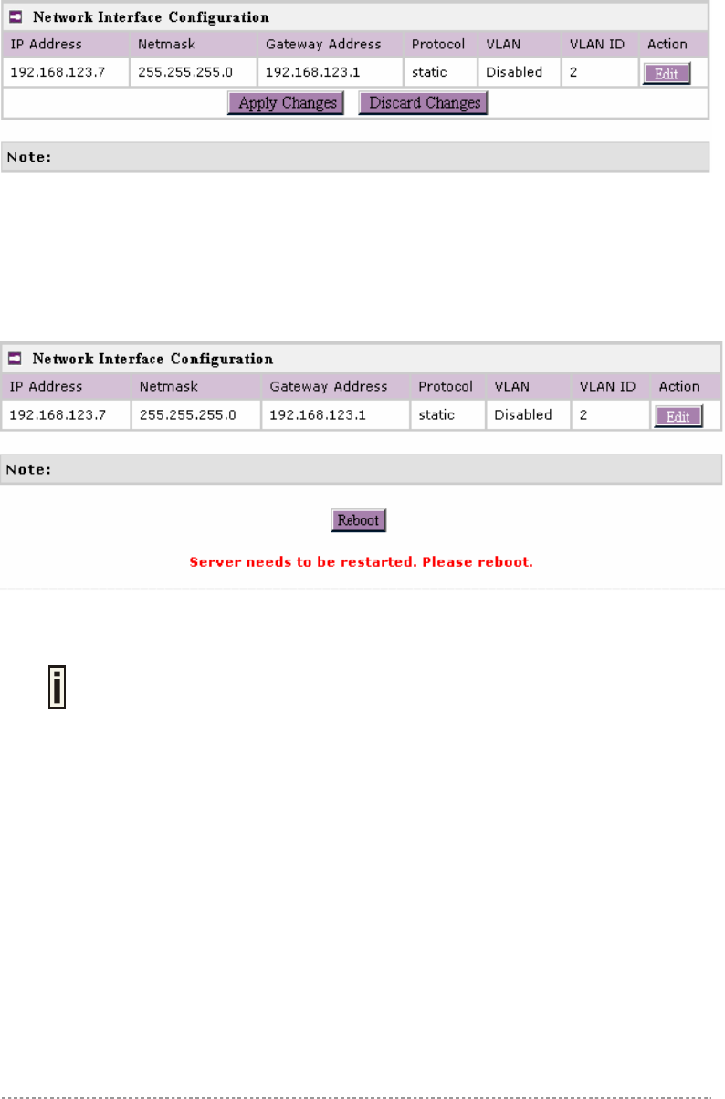
Figure 14 – Apply or Discard Interface Configuration Changes
Apply Changes – to save all changes in the interface table at once.
Discard Changes – restore all previous values.
For such each change of settings, the BW1250 needs to be restarted to apply all settings changes
when clicking Apply Changes. Request for reboot server appears:
Figure 15 – Reboot Server
Reboot – click the button to restart the server and apply the changes.
If there is no other setting needed to be modified, click the Reboot button for
applying all modifications.
And if there are still other setting modifications needed, go ahead to finish all
changes and then click Reboot button to restart and apply all settings together.
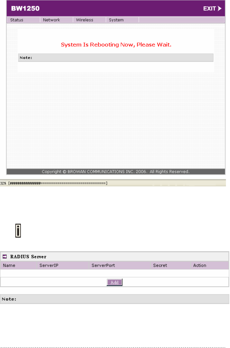
To reboot at once, click Reboot button and then it is necessary to wait a moment. And the message
of reboot appears just like bellows:
BW1250 Sep. 22, 2006
Browan Page 25 of 68
Figure 16 – Reboot Information
Network | RADIUS Server
Up to 32 different RADIUS servers can be configured under the RADIUS servers
menu.
By default, one RADIUS server is specified for the system:
Figure 17 – RADIUS Servers Settings
Add – add new RADIUS server.
Click Add to configure RADIUS server settings.
BW1250 Sep. 22, 2006
Browan Page 26 of 68
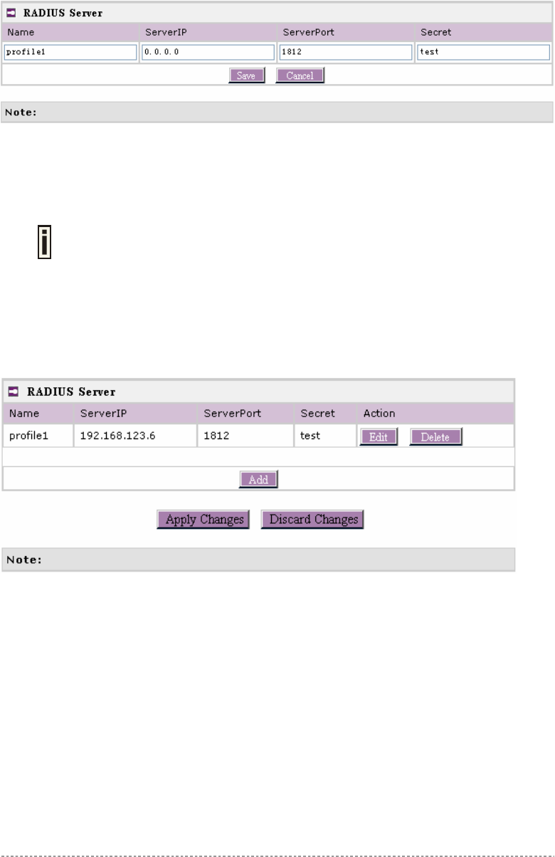
Figure 18 – RADIUS Server's Details
Name – specify the new RADIUS server name which is used for selecting RADIUS server.
Server IP – authentication RADIUS server IP address [dots and digits].
Server Port – specify the network port used to communicate with RADIUS [1-65535].
The default port value for authentication is 1812.
The default port value for accounting is 1813.
The port specified here must be the same with the one on the RADIUS server.
Secret – shared secret string that is used to make sure the integrity of data frames used for
authentication server.
Save – add new specified RADIUS server.
Cancel – restore all previous values.
After adding a new RADIUS server or editing an existing one, the following control appears:
Figure 19 – Apply or Discard RADIUS Server Changes
Edit – edit an existing RADIUS server settings
Delete – delete an existing RADIUS server settings
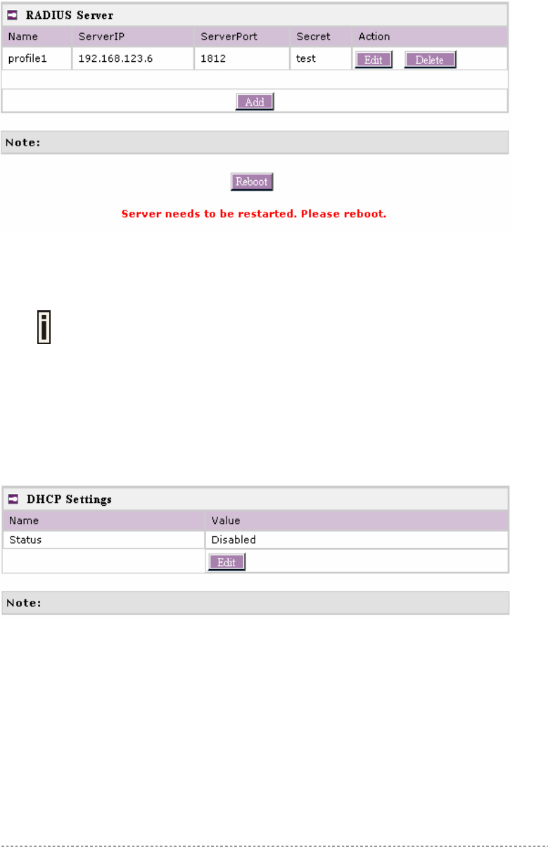
Click Apply Change to apply all the changes. Then the follow similar page will appear:
BW1250 Sep. 22, 2006
Browan Page 27 of 68
Figure 20 – Reboot Server
Reboot – restart the access point to make applied changes work.
If there is no other setting needed to be modified, click the Reboot button for
applying all modifications.
And if there are still other setting modifications needed, go ahead to finish all
changes and then click Reboot button to restart and apply all settings together.
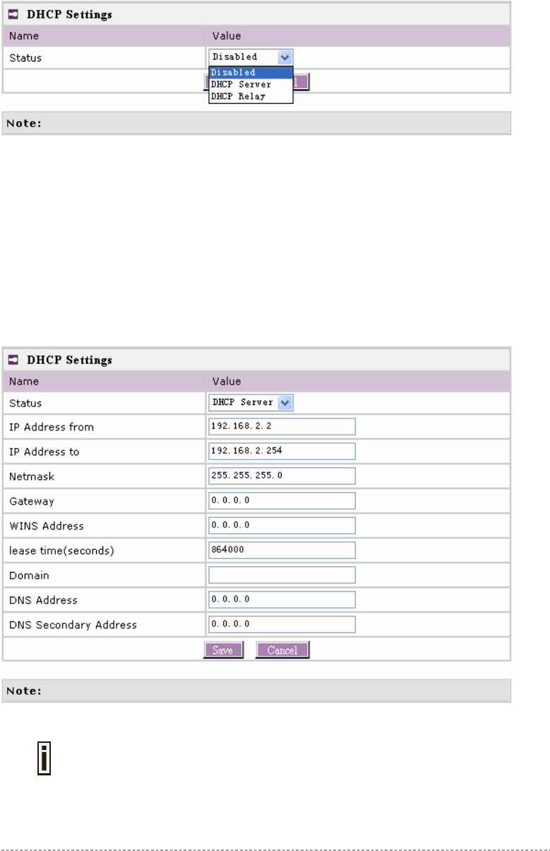
Network | DHCP Settings
BW1250 can act as DHCP server or DHCP relay. The DHCP (Dynamic Host Configuration Protocol)
service is supported on layer 2 interfaces.
DHCP server and DHCP relay is disabled by default.
Figure 21 – DHCP Settings
Edit – edit the wireless basic settings
To change DHCP setting properties click the Edit button, the DHCP server or DHCP relay service
should be configured:
BW1250 Sep. 22, 2006
Browan Page 28 of 68
Figure 22 – DHCP Settings
Status – select status from the drop-down menu.
Disabled – disable the DHCP server service.
DHCP Server – enable the DHCP server service.
DHCP Relay – enable the DHCP Relay service.
Choose DHCP Server to enable DHCP server service. Choose DHCP Relay to enable DHCP relay
service.
DHCP Server
This DHCP server service enables clients on the LAN to request configuration information, such as IP
address from a server. Settings of the DHCP service can be viewed just like the follow page.
Figure 23 – DHCP server Settings
By default, DHCP server is disabled for BW1250.
IP Address from / IP Address to – specify the IP address range to be dynamically allocated by the
DHCP server.
Netmask – enter the netmask for IP pool range.
BW1250 Sep. 22, 2006
Browan Page 29 of 68
Gateway – enter the gateway IP for wireless clients.
WINS Address (Windows Internet Naming Service) – specify server IP address if it is available on the
network [dots and digits].
Lease Time – specify the IP address lease interval in seconds [1-1000000].
Domain – specify the DHCP domain name [optional, 1-128 sting].
DNS address – specify the DNS server’s IP address [in digits and dots notation].
DNS secondary address – specify the secondary DNS server’s IP address [in digits and dots
notation].
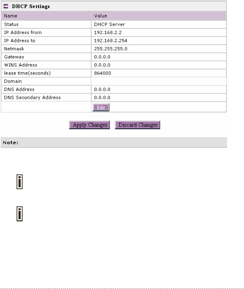
Change status or leave in the default state if no editing is necessary and click the Save button.
Figure 24 – Apply or Discard DHCP server Settings
The DHCP server settings will be automatically adjusted to match the network
interface settings.
The Gateway of DHCP server settings must be same with the Gateway of BW1250
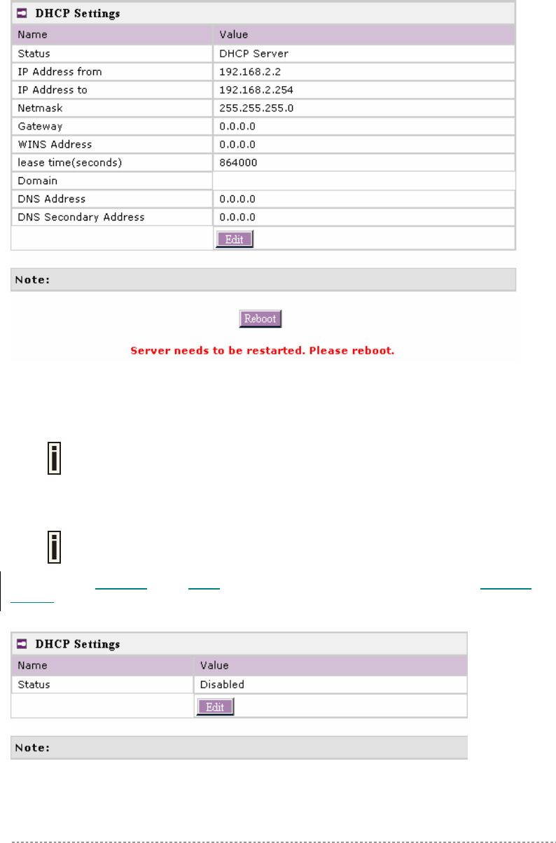
For each change of settings, the BW1250 needs to be restarted to apply all settings changes when
clicking Apply Changes. Request for reboot server appears:
BW1250 Sep. 22, 2006
Browan Page 30 of 68
Figure 25 – Reboot information
Reboot – click the button to restart the server and apply the changes.
If there is no other setting needed to be modified, click the Reboot button for
applying all modifications.
And if there are still other setting modifications needed, go ahead to finish all
changes and then click Reboot button to restart and apply all settings together.
When BW1250 network Interface uses DHCP to get IP address dynamically, DHCP
server service cannot be enabled.
When BW1250 serves as DHCP client to get IP address, the similar WEB UI will appear as below
diagram:
Figure 26 – Warning information
DHCP Relay
BW1250 Sep. 22, 2006
Browan Page 31 of 68
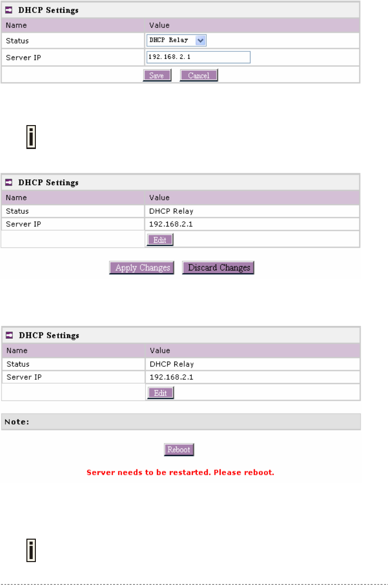
To route DHCP through the external server, enable the DHCP Relay service.
Figure 27 – DHCP Relay settings
Server IP – enter the IP address of the external DHCP server.
Only one DHCP server can be supported for DHCP relay feature.
Change status or leave in the default state if no editing is necessary and click the Save button.
Figure 28 –Apply or Discard DHCP relay Settings
For each change of settings, the BW1250 needs to be restarted to apply all settings changes when
clicking Apply Changes. Request for reboot server appears:
Figure 29 – Reboot information
Reboot – click the button to restart the server and apply the changes.
If there is no other setting needed to be modified, click the Reboot button for
applying all modifications.
And if there are still other setting modifications needed, go ahead to finish all
changes and then click Reboot button to restart and apply all settings together.
BW1250 Sep. 22, 2006
Browan Page 32 of 68
When BW1250 network interface uses DHCP to get IP address dynamically, DHCP
relay service cannot be enabled.
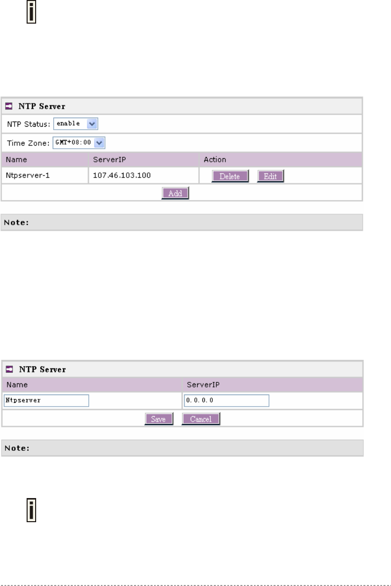
Network | NTP Settings
NTP (Network Time Protocol) is used to synchronize the system time with the selected network NTP
server. Use the Network| NTP Settings menu to configure the NTP service:
Figure 30 – NTP Settings
NTP Status – specify enable or disable this NTP service.
Time Zone – specify the time zone for NTP service.
Delete – delete the existed NTP server.
Edit – edit the settings of the existed NTP server.
Add – add a new NTP server setting for synchronizing time.
Clicking Add button to add a new NTP server:
Figure 31 – Add new NTP server setting
Two NTP servers can be configured under Network | NTP Settings menu. And
only IP address is accepted for NTP server.
It is required to add at least one NTP server before enable NTP service.
BW1250 Sep. 22, 2006
Browan Page 33 of 68
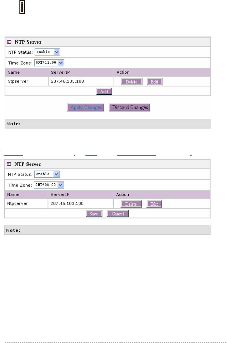
The Name of NTP server should be unique.
Change status or leave in the default state if no editing is necessary and click the Save button.
Figure 32 – Apply or Discard NTP server Changes
Choose the Time Zone for your local area time and enable or disable the NTP status.
Figure 33 – Edit Time Zone setting/NTP status
Click Save button to save new Time Zone setting.
BW1250 Sep. 22, 2006
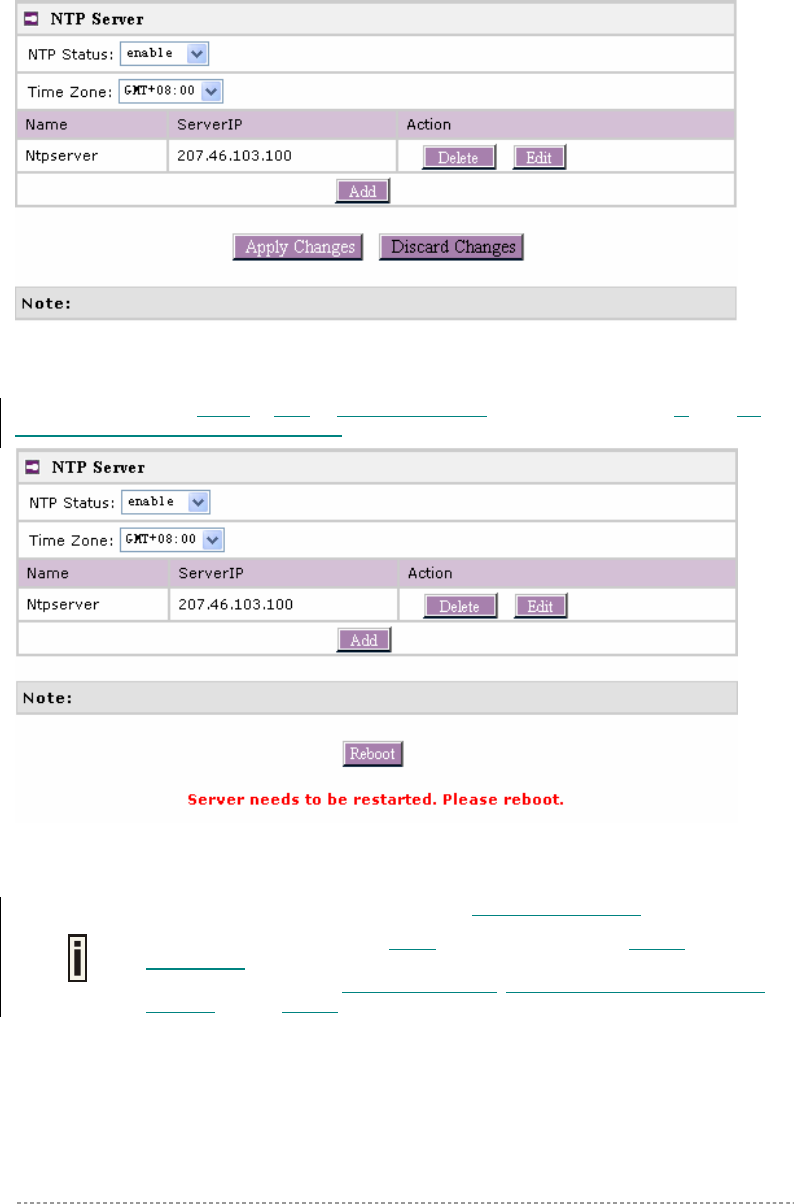
Browan Page 34 of 68
Figure 34 – Apply or Discard Time Zone/NTP status Changes
BW1250 needs to be rebooted to save all configuration. After clicking Apply Changes, reboot the
device is then requested as below diagram:
Figure 35 – Reboot information
Reboot – click the button to restart the server and save the configuration you edit..
If there is no other setting to be edited, click the Reboot button to save all
configuration.
And if there are still other settings to be edited, you can ignore the reboot request
until you finish all editing,
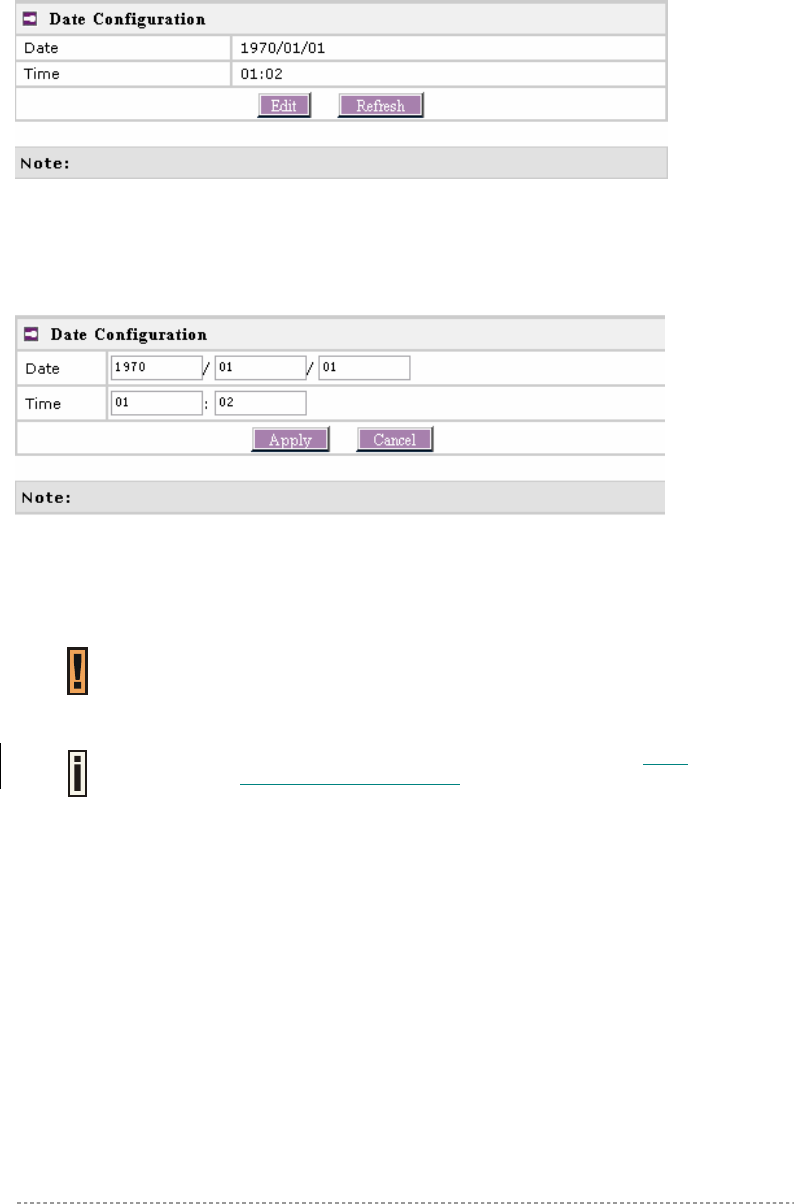
Network | Time Settings
Configure the system time manually under Network | Time Settings menu.
BW1250 Sep. 22, 2006
Browan Page 35 of 68
Figure 36 – Time Settings
Click Edit to change current system time.
Figure 37 – Edit Date and Time Settings
Change the Date and Time or leave in the default value if no editing is necessary and click the Apply
button. Thus the modified time will be taken effect at once. No reboot is needed.
If NTP is enabled, the local time cannot be modified.
Since BW1250 hasn’t RTC (real-time clock), the system time will show 1970/01/01
00:00 when the device reboots each time.
Wireless
Wireless | Basic
Use the wireless | Basic menu to configure such wireless settings as regulatory domain, channel,
band, layer2isolation. Click the edit button on the setting you need to change:
BW1250 Sep. 22, 2006
Browan Page 36 of 68
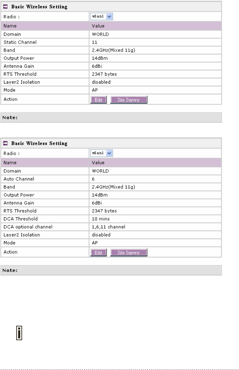
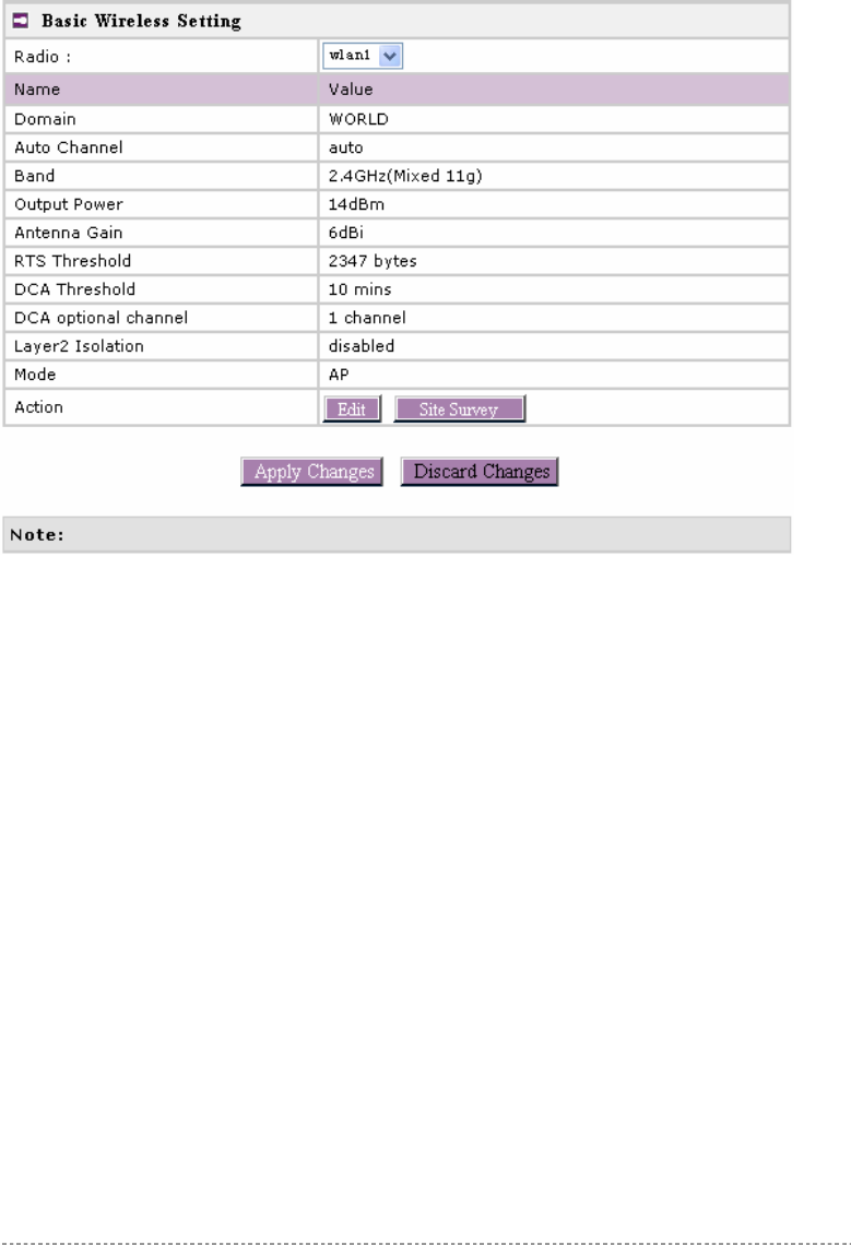
Figure 38 – Basic Wireless Settings with static channel selection
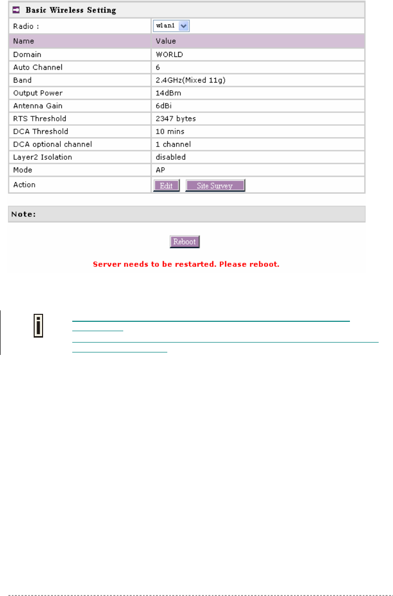
Figure 39 – Basic Wireless Settings with DCA enabled
Radio – specify which wireless interface of BW1250 is shown.
Domain – show the regulatory domain.
Static Channel / Auto Channel – show the channel that the access point will use to transmit and
receive information.
If DCA (Dynamic Channel Allocation) is enabled, this will show Auto Channel and
its channel number is chosen by auto channel selection.
If use static channel, this will show Static Channel and its channel number.
19
19

BW1250 Sep. 22, 2006
Browan Page 37 of 68
DCA (Dynamic Channel Allocation) is a very useful feature to help choose the best
channel automatically and reduce interference among many Access Points.
Band – show the working band on which your radio is working.
Five bands are supplied: 5GHz (11a), 2.4GHz (Mixed 11g), 2.4GHz (11g only), 2.4GHz (Mixed
11g WiFi) and 2.4GHz (11g only WiFi).
2.4GHz (Mixed 11g) or 2.4GHz (11g only) – the radio will work on 2.4GHz for a better
performance. 2.4GHz (11g only) mode only allows 11g client access. 2.4GHz (Mixed 11g) mode
allows 11b/11g client access.
2.4GHz (Mixed 11g WiFi) or 2.4GHz (11g only WiFi) – make sure to comply with Wi-Fi.
5GHz (11a) – the radio will work on 5GHz 11a mode.
Only under Bridge mode, Turbo Mode 11a can be set.
Output Power - indicates output power of the RF card in dBm, antenna gain is not included.
Antenna Gain – show the antenna gain that this Access Point used.
RTS Threshold –show the value of RTS threshold. Default is 2347 which means that RTS is disabled.
DCA threshold – show the value (in minutes) of DCA threshold. This threshold is been used to judge
if there is no wireless users connected during this time. And if yes, BW1250 will monitor the
environment and adjust channel for the best operational one.
DCA optional channel – show the channels only in which auto channel selection (DCA) will be
processed to reduce interference.
Only when DCA is enabled, DCA threshold and DCA optional channel will be
shown.
Layer 2 Isolation – show the status of Layer 2 Isolation service (enabled or disabled)
Mode – show the mode that the Access Point is in. (AP mode or Bridge mode)
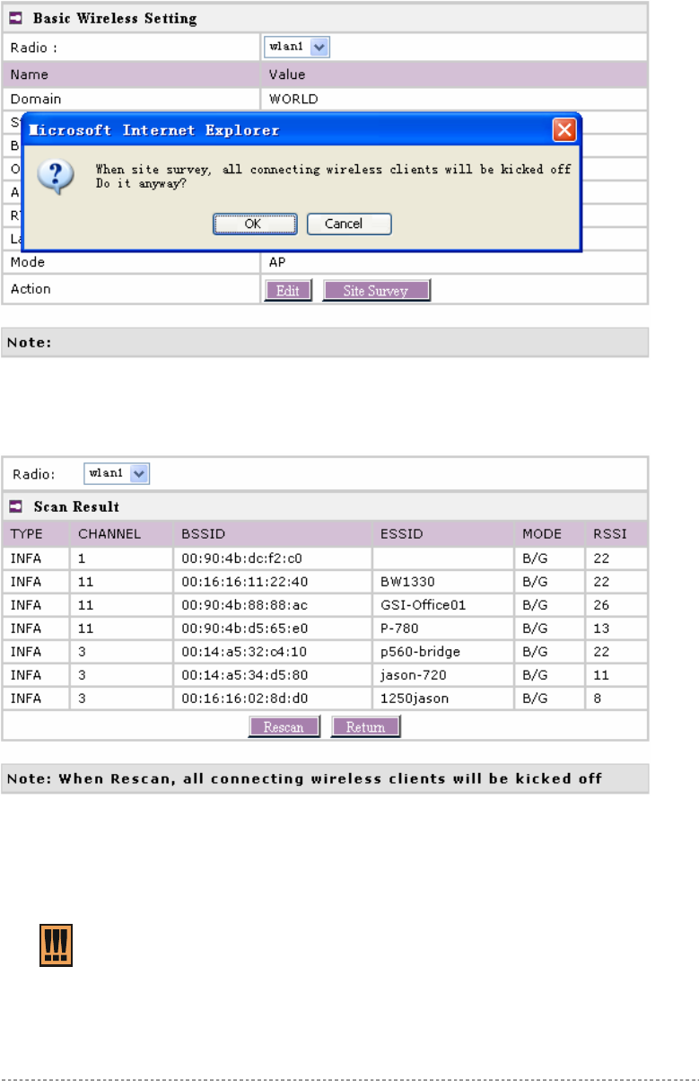
Site Survey – perform survey to show overview information for wireless networks in a local
geography
The site survey shows overview information for wireless networks in a local geographic area. Using
this survey, administrator can scan for working access points, check their operating channels, and see
RSSI levels. To start the scan, simply click the Site Survey menu.
After clicking Site Survey, you will see the follow warning message:
BW1250 Sep. 22, 2006
Browan Page 38 of 68
Figure 40 – Site Survey warning
Click OK to continue site survey and get the similar UI:
Figure 41 – Site Survey information
To refresh the statistics click the Rescan button.
During Site Survey, all wireless clients which are connecting with BW1250 would
be kicked off.
Site Survey takes some minutes to perform. Please wait and don’t power off AP
during site survey.
Edit – edit the wireless basic settings
BW1250 Sep. 22, 2006
Browan Page 39 of 68
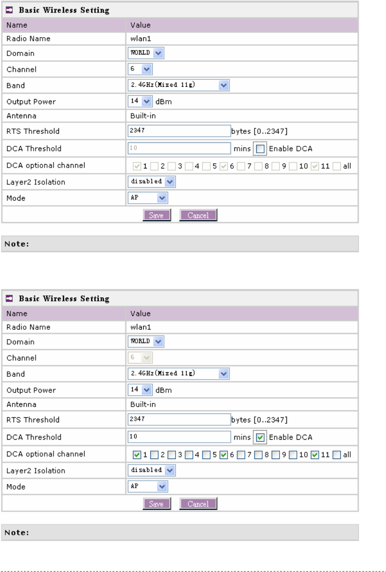
To change basic wireless setting properties click the Edit button in the Action column. The status
can be changed now:
Figure 42 – Edit Basic Wireless Settings with static channel selection
Figure 43 – Edit Basic Wireless Settings with DCA enabled
19
19 dBm

BW1250 Sep. 22, 2006
Browan Page 40 of 68
Radio Name – specify which wireless interface of BW1250 is shown
Domain – select the regulatory domain according to your country
The full frequency range of the 2.4 GHz or 5 GHz is not permitted for use in all countries. Depending
on your selection of regulatory domains, the available frequency channels will vary.
Before changing radio settings manually, make sure that your settings comply with
government regulations. At all times, it ‘s the responsibility of the end-user to
ensure that the installation complies with local radio regulations. Refer to the
Appendix:
C) Regulatory Domain/Channels.
Channels – select the channel that the access point will use to transmit and receive information. If
one channel is defined, it acts as default channel. Channels list will vary depending on selected
regulatory domain and selected band. Multiple frequency channels are used to avoid interference
between two radios of this AP, and between nearby access points. If you wish to operate more than
one access point in overlapping coverage areas, we recommend a distance of at least four channels
between the chosen channels. For example, for three Access Points in close proximity choose
channels 1, 6 and 11 for 11b/g or channels 36, 40 and 64 for 11a.
Band – working band on which your radio is working.
Five bands are supplied: 5GHz (11a), , 2.4GHz (Mixed 11g), 2.4GHz (11g only), 2.4GHz (Mixed
11g WiFi) and 2.4GHz (11g only WiFi).
If 2.4GHz (Mixed 11g) or 2.4GHz (11g only) is selected, the radio will work on 2.4GHz for a better
performance. 2.4GHz (11g only) mode only allows 11g client access. 2.4GHz (Mixed 11g) mode
allows 11b/11g client access.
2.4GHz (Mixed 11g WiFi) or 2.4GHz (11g only WiFi) can make sure to compatible with Wi-Fi.
If 5GHz (11a) is selected, the radio will work on 5GHz 11a mode.
Only under Bridge mode, Turbo Mode 11a can be set.
Output Power - indicates output power of the RF card in dBm, antenna gain is not included.
Total Output Power (EIRP) = Antenna Gain + RF card output power
The range of the EIRP varies with channel and regulatory domain.
Antenna – show the type of Antenna.
RTS Threshold – when set, this settings specifies the maximum packet size beyond which RTS/CTS
mechanism is be invokes. The value range of this is [0 …2347]. Default is 2347 which means that
RTS is disabled.
Enable DCA – Enable or Disable DCA service. DCA can help to choose the best working channel
automatically. And static channel selection will be forbidden if DCA is enabled.
DCA(Dynamic Channel Allocation) solution automatically select the optimal operational frequency
channel when power up and periodically monitors the environment and adjusts for the best
operational frequency channel.
BW1250 Sep. 22, 2006
Browan Page 41 of 68
DCA service is available only under 2.4GHz band.
DCA threshold – specify the value (in minutes) of DCA threshold. This threshold is been used to
judge if there is no wireless users connected during this time. And if yes, BW1250 will monitor the
environment and adjust channel for the best operational one.
If wireless network environment is stable which means auto channel selection
needn’t do frequently, set a big value for DCA threshold to gain a stable wireless
users’ connection.
If wireless network environment changes continually, frequent auto channel
selection is needed. So set a relative small value for DCA threshold to let channel
change based on wireless environment.
Wireless users will be kicked off when DCA is processing (site survey and new
operational frequency channel takes effect).
DCA optional channel – specify the channels only in which auto channel selection (DCA) will choose
for reducing interference reference.
Only when DCA is enabled, DCA threshold and DCA optional channel will be
shown.
Layer 2 Isolation – layer2 wireless client separation. Connected clients with user isolation function
enabled cannot access each other directly. The clients are isolated from each other using their MAC
addresses [enabled/disabled].
Mode – two modes are supplied: AP mode and Bridge mode.
Change status or leave in the default state if no editing is necessary and click the Save button.
19
BW1250 Sep. 22, 2006
Browan Page 42 of 68
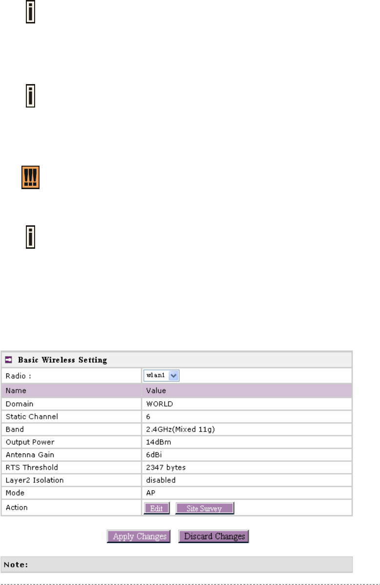
Figure 44 – Apply or Discard Basic Wireless Settings with Static Channel selection
Figure 45 – Apply or Discard Basic Wireless Settings with DCA enabled
For such each change of settings, the BW1250 needs to be restarted to apply all settings changes
when clicking Apply Changes. Request for reboot server appears:
19
BW1250 Sep. 22, 2006
Browan Page 43 of 68
Figure 46 – Reboot Server
Reboot – click the button to restart the server and apply the changes.
If there is no other setting to be edited, click the Reboot button to save all
configuration.
And if there are still other settings to be edited, you can ignore the reboot request
until you finish all editing,
19
BW1250 Sep. 22, 2006
Browan Page 44 of 68
Wireless | Advance
BW1250 supports Multiple BSSID (MBSSID) function. You can configure up to 16 BSSIDs per radio
on BW1250 and assign different configuration settings to each BSSID. For wireless users, they can
think BW1250 as single AP with multi service supporting, including different security policy, different
VLAN ID, different authentication etc. All the BSSIDs are active at the same time that means client
devices can associate to the access point for specific service. Use the Wireless | Advance menu to
configure properties related to Multiple BSSID, including configure SSID, Hidden SSID, VLAN, and
Security for each SSID.
Each BSSID can have its own SSID. In this case, Multiple BSSID is the same with
Multiple ESSID. Wireless users can think BW1250 as multiple virtual APs, each
supporting different service, and connects one SSID for the special services.
Also, BW1250 supports Bridge function, it can support up to 8 Bridge links per radio. Different
bridge link can use different WEP key index.
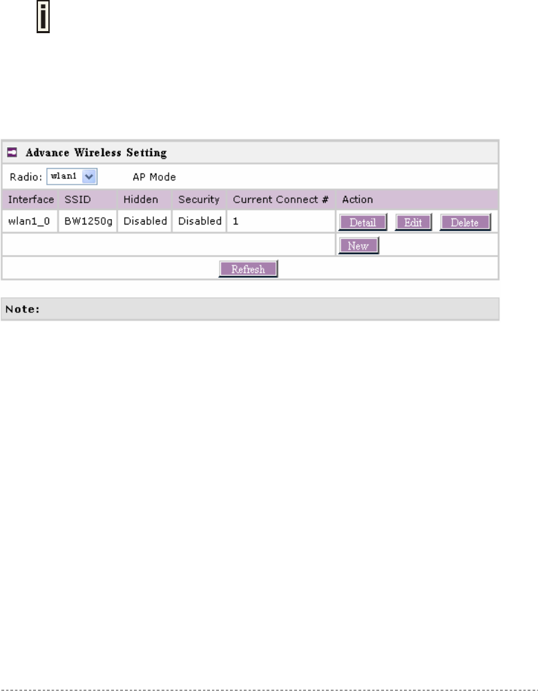
AP Mode:
Figure 47 – Advanced Wireless Setting (AP Mode)
Radio – specify which RF card (wlan1 or wlan2) is needed to be configured since BW1250 has two
Dual-Band radios
Mode – specify the operation mode of BW1250 (AP or Bridge)
Interface – choose the specified MBSSID entry you want to configure. Each Interface maps to a
BSSID
Hidden – show the status of Hidden SSID feature
Security – show which security policy is used for this MBSSID entry
Current Connect # – show the number of current wireless clients who are connecting with this
MBSSID
New – create a new MBSSID entry
Detail – show the detail information of this MBSSID entry
Edit – edit the selected MBSSID entry you want to configure
Delete – delete the selected MBSSID entry. When in AP mode, you can not delete the last entry
Refresh – rescan the WEB page to get newer information
Clicking Detail, a similar page will be appears as below:
BW1250 Sep. 22, 2006
Browan Page 45 of 68
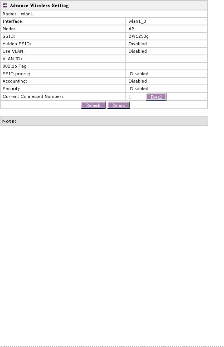
Figure 48 – Detail for MBSSID entry
Radio – show which radio (WLAN1 or WLAN2) is displayed
Interface – show the sub-interface of specified Radio
Mode – Show the operation mode of the sub-interface
SSID – Show the SSID value of the sub-interface
Hidden SSID – Show the enable/disable status of Hidden SSID service
Use VLAN – Show if VLAN is used for the sub-interface
VLAN ID – If used VLAN, show the VLAN ID which is specified
802.1p Tag – Show the 802.1p tag for the sub-interface if 802.1p is used
SSID priority – Show the traffic priority specified for this sub-interface( BSSID/SSID), 0 means the
normal priority
Accounting – Show the enable/disable status of accounting service
Security – Show the security policy specified for this sub-interface
Current Connect Number – Show the number of current connected client with this sub-interface
Detail – show the MAC address of current connected clients
Refresh – rescan the WEB page to get newer information
Return – return to the wireless advance settings page
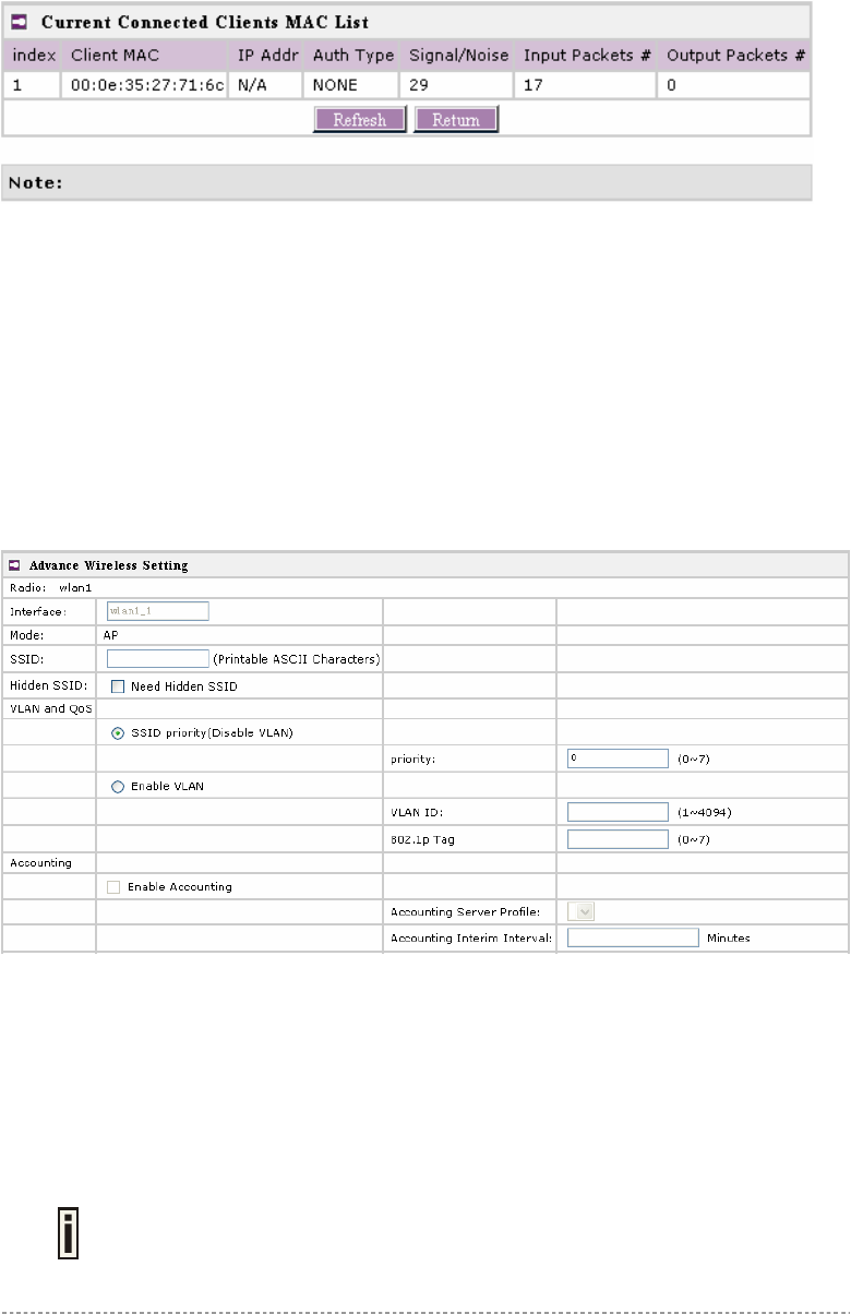
Click Detail to check the detail information of the connected client just like below:
BW1250 Sep. 22, 2006
Browan Page 46 of 68
Figure 49 – Detail information of connected client
Client MAC – show the connected client’s MAC address
IP Addr – show the IP address of the connected client
Auth Type – show the security policy that the connected client is used
Signal/Noise – show the SNR value of the connected client
Input Packets – show the packet number transmitted by the connected client
Output Packets – show the packet number destined to the connected client
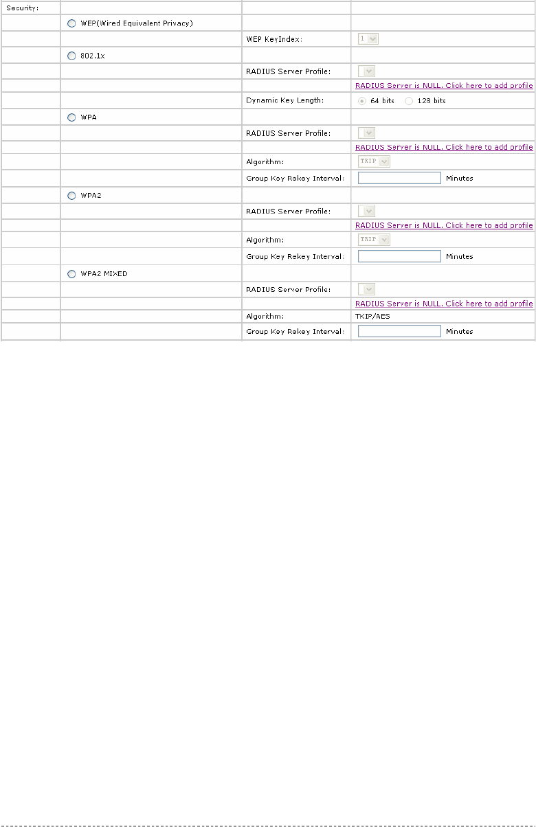
Clicking New or Edit on AP mode, the settings of MBSSID entry appears:
Figure 50 – Multiple BSSID Setting -1
Radio – showing which RF card (wlan1 or wlan2) is being configured.
Mode – showing the current operation mode of BW1250 (AP or Bridge).
Interface – showing the current MBSSID | Bridge link entry
SSID – a unique ID for your wireless network. It is case sensitive and must not exceed 32 characters.
The default SSID is "BW1250" but you should change this to a personal wireless network name. The
SSID is important for clients when connecting to the access point. All client stations must have their
client SSID settings configured and must use the same SSID.
Each MBSSID entry (BSSID) can has its own SSID. And SSID can be same for
different BSSID

BW1250 Sep. 22, 2006
Browan Page 47 of 68
Hidden SSID – when enabled, the SSID of this Interface is invisible in the networks list while
scanning the available networks for wireless client (SSID is not broadcasted with its Beacons). When
disabled, the AP’s SSID is visible in the available network list [enabled/disabled]. By default the
Hidden SSID is disabled.
VLAN and QoS – specify VLAN policy or QoS policy. Data priority is based on (B)SSID and is
implemented by 802.11e EDCA or 802.1p tag.
SSID priority (Disable VLAN) – specify the data priority, which is implemented according to
802.11e EDCA and makes sure the wireless downlink QoS. This priority is based on (B)SSID,
which means different BSSID can have different data priority and the data of the same BSSID has
the same priority.
This data priority only makes sure the priority of downlink (from AP to wireless
client).
8 levels priorities are supplied. 1, 2, 0, 3, 4, 5, 6, 7 is from lowest priority to highest
priority.
And if no special QoS is needed, leave priority to default (0). 0 means normal
priority.
Enable VLAN – when enabled, the outgoing packets from this SSID device will be tagged with
VLAN ID and 802.1p tag (If have).
VLAN ID – configure VLAN ID for each Multiple SSID devices. Valid numbers are from 1 to
4094.
802.1p Tag – configure 802.1p Tag for remote APC’s or Router’s QoS uses. Valid numbers
are from 0 to 7.
VLAN ID and 802.1p tag must cooperate with remote Router or APC.
Accounting – Control the status of accounting service
Enable Accounting – enable or disable the accounting service.
Accounting service only can be enabled when the security policy using RADIUS
server is chosen. The security policies using RADIUS server include 802.1x, WPA,
WPA2, WPA2 MIXED and MAC auth.
Accounting Server Profile – specify which RADIUS server is used for accounting service. If
not have any RADIUS server, please configure Network | RADIUS Servers Web UI first.
Accounting Interim Interval – specify the value (in minutes) which is used for interim-
accounting interval, which is helpful for statistics.
BW1250 Sep. 22, 2006
Browan Page 48 of 68
Figure 51 – Multiple BSSID Setting – 2
Security – specify the security policy.
WEP – when selected, the privacy of MSSID entry will be set to WEP (Wired Equivalent Privacy).
WEP Key Index – select the default key Index to make it the Default key and encrypt the
data before being transmitted. All stations, including this MSSID Entry, always transmit data
encrypted using this Default Key. The key number (1, 2, 3, 4) is also transmitted. The
receiving station will use the key number to determine which key to use for decryption. If the
key value does not match with the transmitting station, the decryption will fail. The key value
is set in Wireless | WEP web page.
802.1x – when selected, the MSSID entry will be configured as an 802.1x authenticator. It
supports multiple authentication types based on EAP (Extensible Authentication Protocol) like
EAP-TLS, EAP-TTLS, EAP-PEAP, EAP-SIM. The privacy will be configured as dynamic WEP.
RADIUS Server Profile – select the default radius server name. If not, please configure
Network | RADIUS Servers Web page first.
Dynamic Key Length – select the dynamic 64-bits / 128-bits encryption.
WPA – Wi-Fi Protected Access, When selected, the encrypt method will be WPA with RADIUS
Sever.
WPA2 – when selected, the security policy will be WPA2 with RADIUS server. In this mode, WPA
client is not permitted to connect.
WPA2 MIXED – when selected, WPA2 client and WPA client are all permitted to connect.
RADIUS Server Profile – select the default radius server name. If not, please configure
Network | RADIUS Servers Web page first.
Algorithm – choose WPA algorithm (TKIP, AES).
Group Key Rekey Interval – specify amount of minutes and WPA automatically will
generate a new Group Key.
BW1250 Sep. 22, 2006
Browan Page 49 of 68
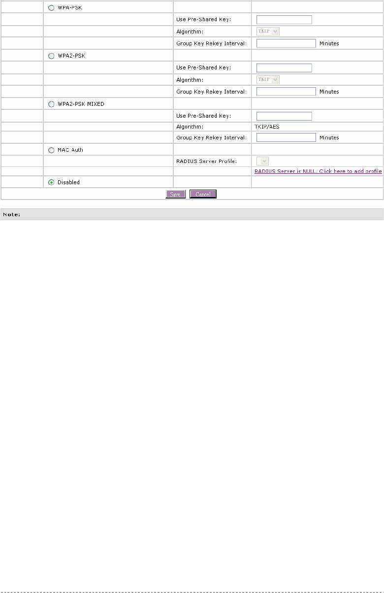
Figure 52 – Multiple BSSID Setting – 3
WPA-PSK – when selected, the encrypt method will be WPA without RADIUS server.
WPA2-PSK – when selected, the security policy will be WPA2 PSK without RADIUS server. In
this mode, only WPA2 PSK client can connect with AP and WPA PSK client is not permitted to
connect.
WPA2-PSK MIXED – when selected, WPA2 PSK and WPA PSK are all permitted to connect with
AP.
Use Pre-Shared Key – specify more than 8 characters and less than 64 characters for WPA
with pre-shared key encryption.
Algorithm – the same as WPA.
Group Key Rekey Interval – the same as WPA.
MAC Auth – when selected, the MAC address of wireless client will be passed to RADIUS server
for PAP authentication when it connects with BW1250. The MAC address of wireless client acts
as username and password.
RADIUS Server Profile – select the default radius server name. If not, please configure
Network | RADIUS Servers web page first
Disabled – when selected, you don’t select any security policy.
BW1250 Sep. 22, 2006
Browan Page 50 of 68
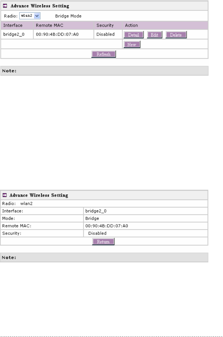
Bridge Mode
Figure 53 – Advanced Wireless Setting (Bridge Mode)
Radio – specify which RF card (wlan1 or wlan2) is needed to be configured since BW1250 has two
Dual-Band radios
Mode – specify the operation mode of BW1250 (AP or Bridge)
Interface – choose the specified Bridge link entry you want to configure.
Remote MAC – specify the remote peer’s MAC address of this Bridge
Security – specify which security policy is used
New – create a new Bridge link entry
Detail – show the detail information of this Bridge link entry
Edit – edit the selected Bridge link entry you want to configure
Delete – delete the selected Bridge link entry.
Clicking Detail, the similar page will be appears:
Figure 54 – Detail of one bridge entry
Clicking Edit for editing an existed bridge link or New for adding a new bridge link, you can see the
figure like this.
BW1250 Sep. 22, 2006
Browan Page 51 of 68
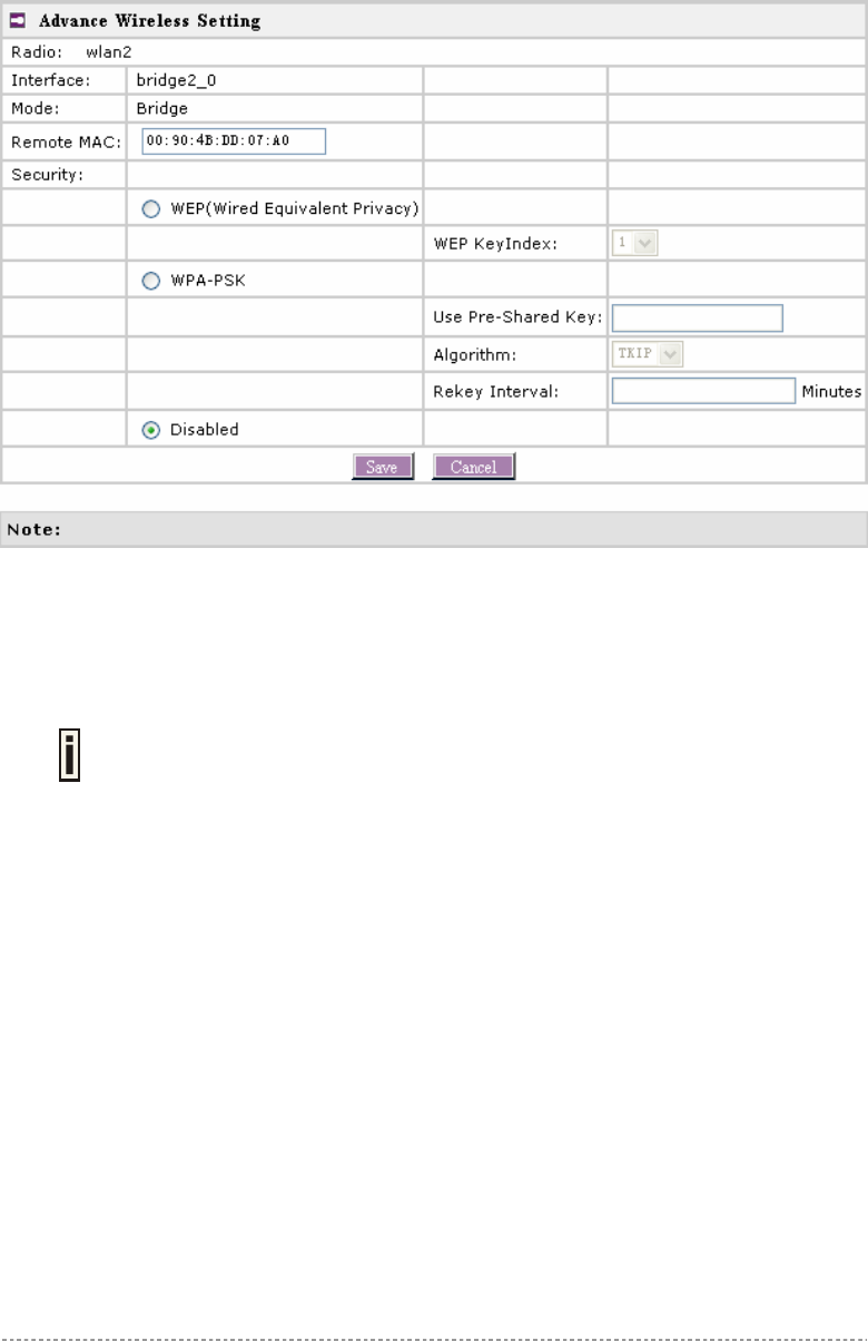
Figure 55 – Bridge Link Setting
Remote MAC – add the remote peer’s MAC address you want to configure as a bridge link
Security – specify WEP or WPA-PSK (TKIP or AES) is used for security policy. WPA-PSK or static
WEP can be used for encrypt each bridge link
Each Bridge link can have its own WEP key/key Index for encryption.
By default, four WEP keys are all set to “6161616161”. They can be modified in
Wireless | WEP.
BW1250 Sep. 22, 2006
Browan Page 52 of 68
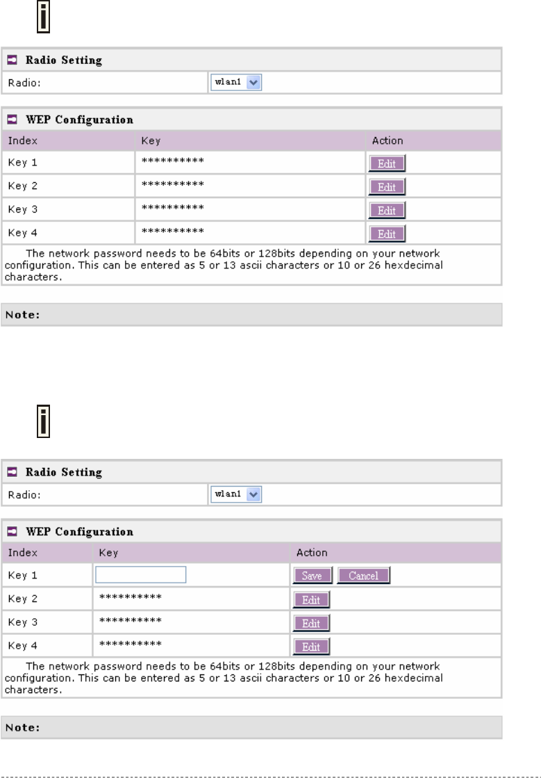
Wireless | WEP
Use the Wireless | WEP menu to configure static WEP settings.
This menu only set static WEP key value related with 4 key indexes for each RF
card (wlan1 or wlan2). Enable or Disable static WEP is in the Wireless | Advance
menu.
Figure 56 – WEP Settings
Radio – specify which RF card (wlan1 or wlan2) is needed to be set.
Click Edit to edit the existing wepkey1 to wepkey4.
By default, four WEP keys are all set to “6161616161”. They can be modified
according to real need.
Figure 57 – Edit WEP Key
BW1250 Sep. 22, 2006
Browan Page 53 of 68
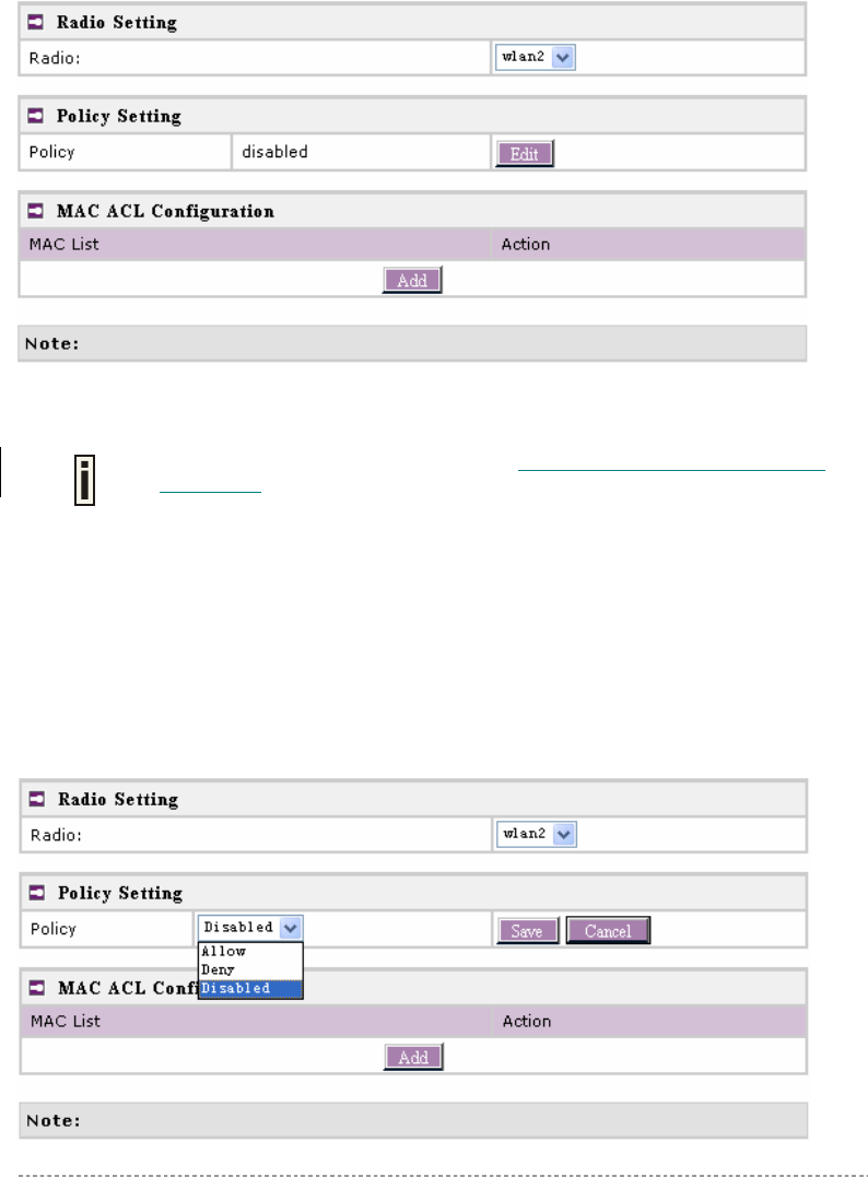
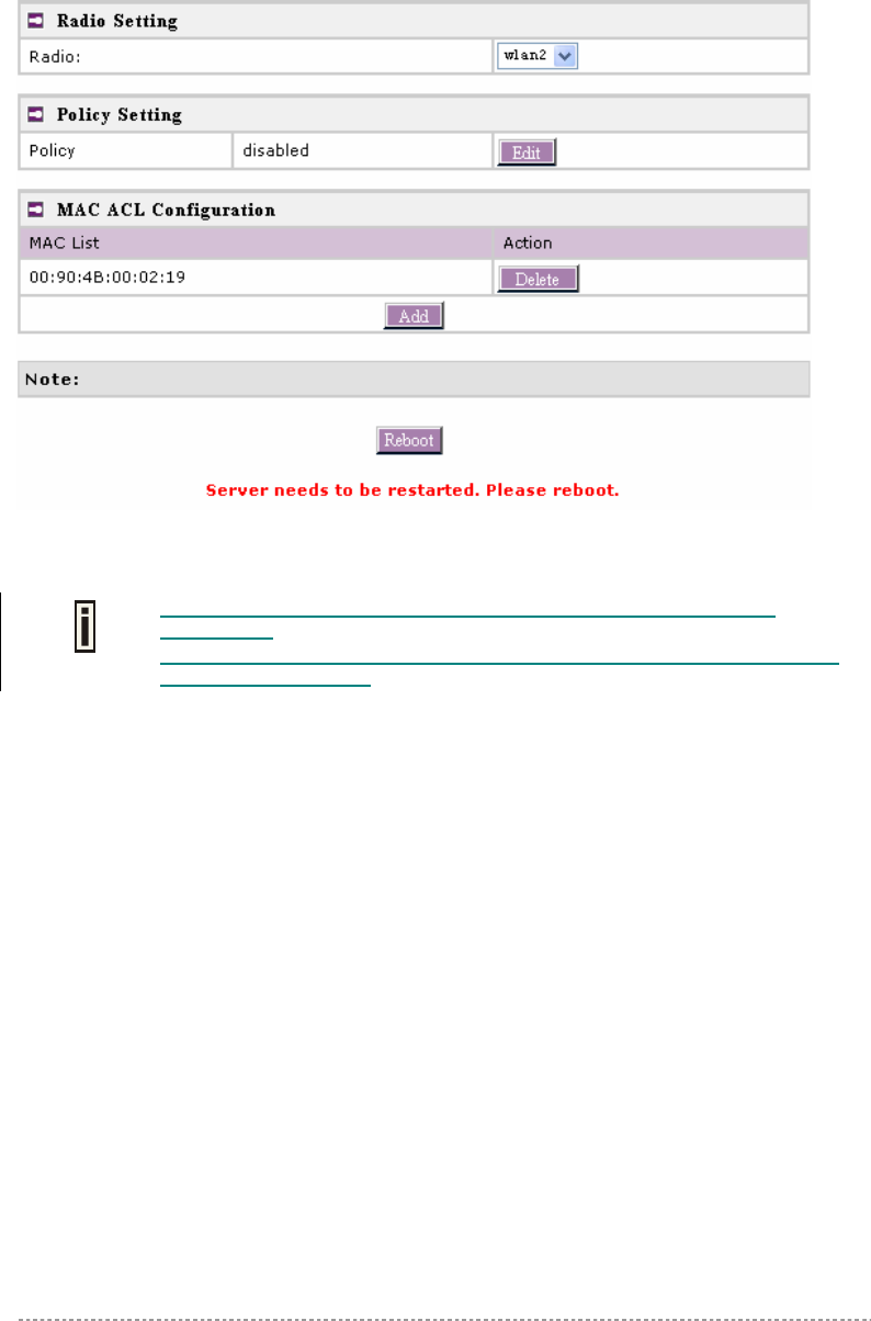
Wireless | MAC ACL
Use the MAC ACL service to control the default access to the wireless interface of the BW1250 or
define special access rules for mobile clients. Configure the ACL using the Wireless | MAC ACL menu:
Figure 58 – MAC ACL Service
Radio – two wireless interfaces wlan1 and wlan2 can be selected for each radio’s MAC ACL rules.
Only AP mode has the MAC ACL service. MAC ACL service.is not available for
Bridge moe.
Policy Setting – click the edit button to choose Allow, Deny or disable the access control service on
device. By default the ACL service is disabled and all wireless clients connecting to the BW1250 are
allowed (no ACL rules are applied to the wireless clients).
Select Allow means only the wireless clients whose MAC are listed in the MAC List would be
permitted to access this AP. Other wireless client cannot access this AP.
Select Deny means only the wireless clients whose MAC are listed in the MAC List would be
prevented from accessing. Other wireless clients can access this AP.
Select Disabled means no ACL service.
Figure 59 – MAC ACL settings
BW1250 Sep. 22, 2006
Browan Page 54 of 68
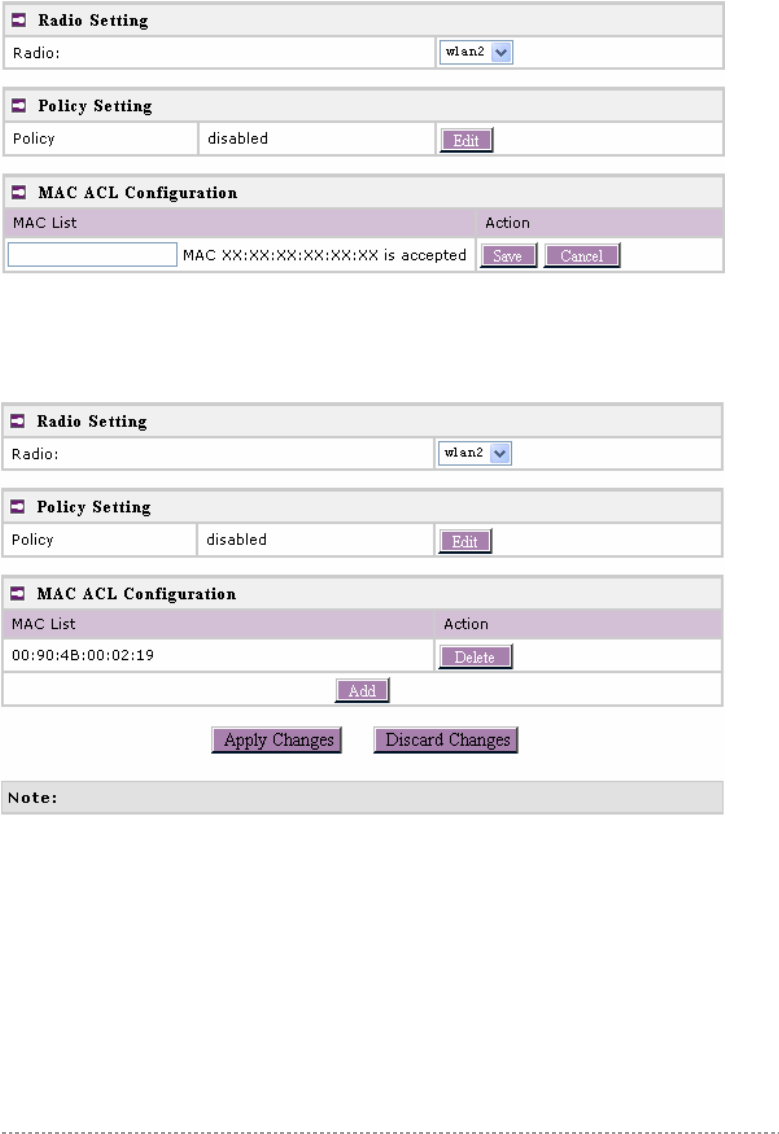
You must create MAC List to work with Policy setting. The access control list is based on the
network device’s MAC address. In the MAC ACL Configuration table, you only need to specify the
MAC address of wireless client. Click the Add button to create a new MAC entry:
Figure 60 – Add MAC entry
MAC Address – enter the physical address of the network device you need to (MAC address) The
format is a list of colon separated hexadecimal numbers (for example: 00:AA:A2:5C:89:56).
Save – click the button to save the new MAC entry.
Figure 61 – Apply or Discard MAC ACL Configuration Changes
Apply Changes – to save all changes made in the interface table at once.
Discard Changes – restore all previous values.
For such each change of settings, the BW1250 needs to be restarted to apply all settings changes
when clicking Apply Changes. Request for reboot server appears:
BW1250 Sep. 22, 2006
Browan Page 55 of 68
Figure 62 – Reboot Server
Reboot – click the button to restart the server and apply the changes.
If there is no other setting to be edited, click the Reboot button to save all
configuration.
And if there are still other settings to be edited, you can ignore the reboot request
until you finish all editing,
BW1250 Sep. 22, 2006
Browan Page 56 of 68
System
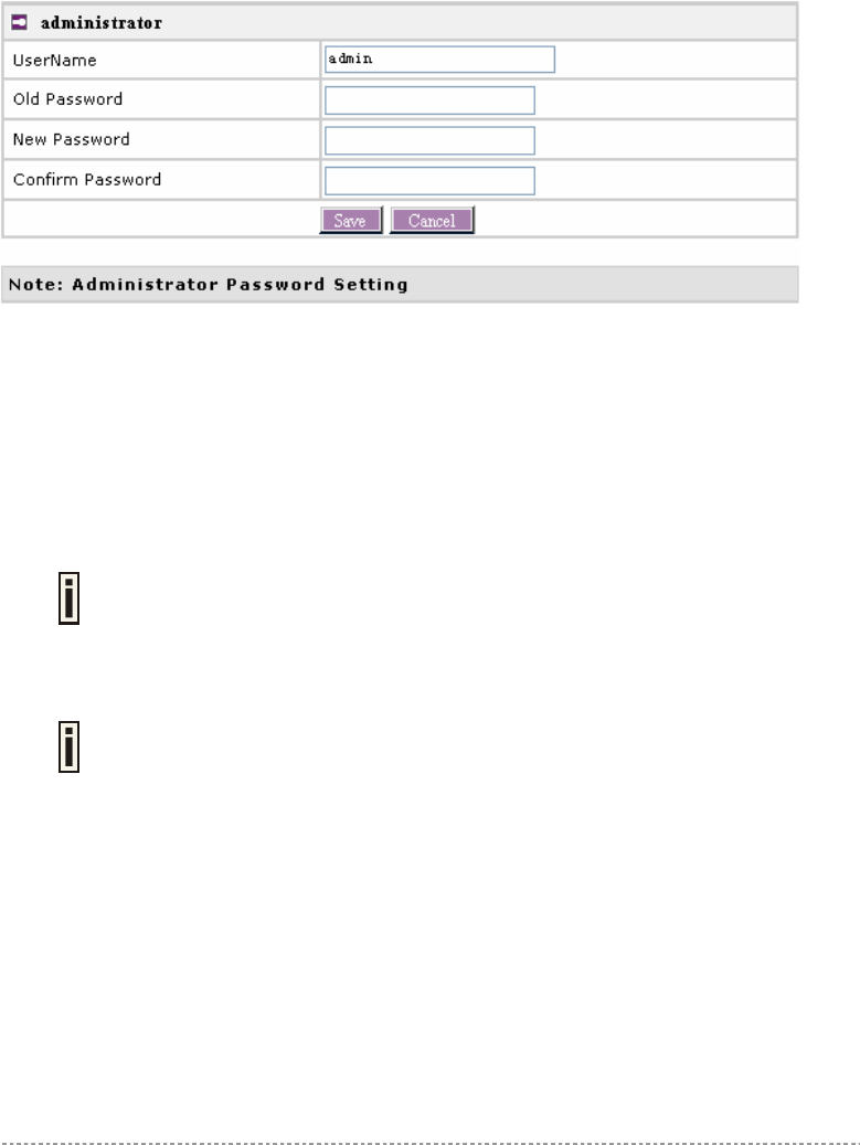
System | Security
Use the System | Security service to configure the name and password administrator:
Figure 63 – system security settings
User Name – administrator username for access to BW1250 (e.g. web interface, CLI mode) [1-32
symbols, spaces not allowed].
Old Password – old password value.
New Password – new password value used for user authentication in the system [4-8 characters,
spaces not allowed].
Confirm Password – re-enter the new password to verify its accuracy.
Save – click to save new administrator settings.
Default administrator logon settings are:
User Name: admin
Password: admin01
Password length is from 4 to 8 characters.
After filling in the right Old password and the New Password, clicking the Save button for taking effect
immediately.
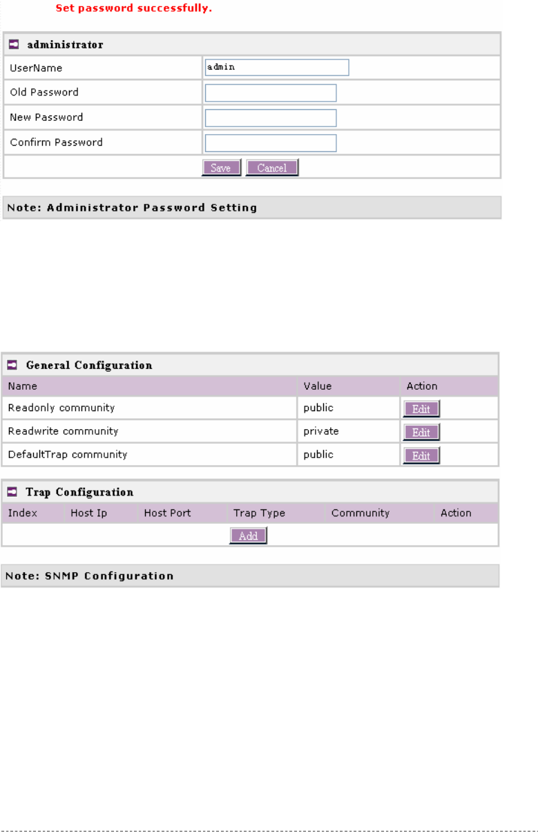
After clicking Save button, the below UI will be shown to notify that the new password setting has
been taken place:
BW1250 Sep. 22, 2006
Browan Page 57 of 68
Figure 64 – system security settings save and take effect successfully
System | SNMP
SNMP is the standard protocol that regulates network management over the Internet. To
communicate with SNMP manager you must set up the same SNMP communities and identifiers on
both ends: manager and agent.
Use the System | SNMP menu to change current SNMP configuration.
Figure 65 – SNMP settings
Readonly community – community name is used in SNMP version 1 and version 2c. Read-only
(public) community allows reading values, but denies any attempt to change values [1-32 all ASCII
printable characters, no spaces].
Readwrite community – community name is used in SNMP version 1 and version 2c. Read-write
(private) community allows to read and (where possible) change values [1-32 all ASCII printable
characters, no spaces].
Default Trap community – the default SNMP community name used for traps without specified
communities. The default community by most systems is "public". The community string must match
the community string used by the SNMP network management system (NMS) [1-32 all ASCII
printable characters, no spaces].
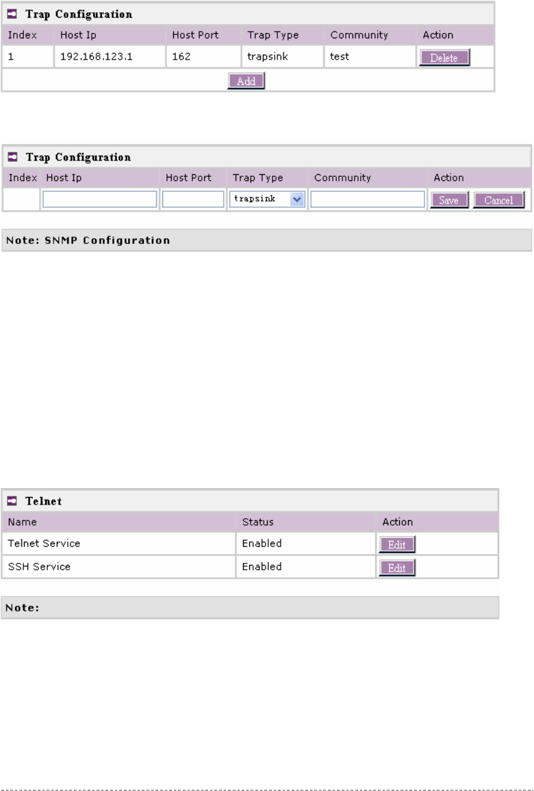
Trap Configuration Table:
BW1250 Sep. 22, 2006
Browan Page 58 of 68
You can configure your SNMP agent to send SNMP Traps (and/or inform notifications) under the
defined host (SNMP manager) and community name (optional).
Figure 66 – SNMP Trap table settings
Click Add to add a new SNMP manager or Delete to delete a specific SNMP manager. Clicking Add:
Figure 67 – Add SNMP Trap
Host IP – enter SNMP manager IP address [dots and digits].
Host Port – enter the port number the trap messages should be send through [number].
Trap Type – select trap message type [v1/v2/inform].
Community – specify the community name at a SNMP trap message. This community will be used in
trap messages to authenticate the SNMP manager. If not defined, the default trap community name
will be used (specified in the SNMP table) [1-32 all ASCII printable characters, no spaces].
Save – save all current settings
Cancel – restore the last settings
System | Telnet
Use System | Telnet menu to manage the telnet/SSH service of your BW1250.
Figure 68 – System Configuration settings
Telnet Service – Enable or disable telnet service of BW1250
SSH Service – Enable or disable SSH service of BW1250.
The default of these two services are all Enabled. The current IETF SSH (SSHv2) is supported for
security of accessing BW1250 via telnet/CLISH.
System | Configuration
Use the System | Configuration menu to configure such system utilities:
BW1250 Sep. 22, 2006
Browan Page 59 of 68
Backup – download current working system configuration for backup
Upload/Restore – upload system configuration for restore
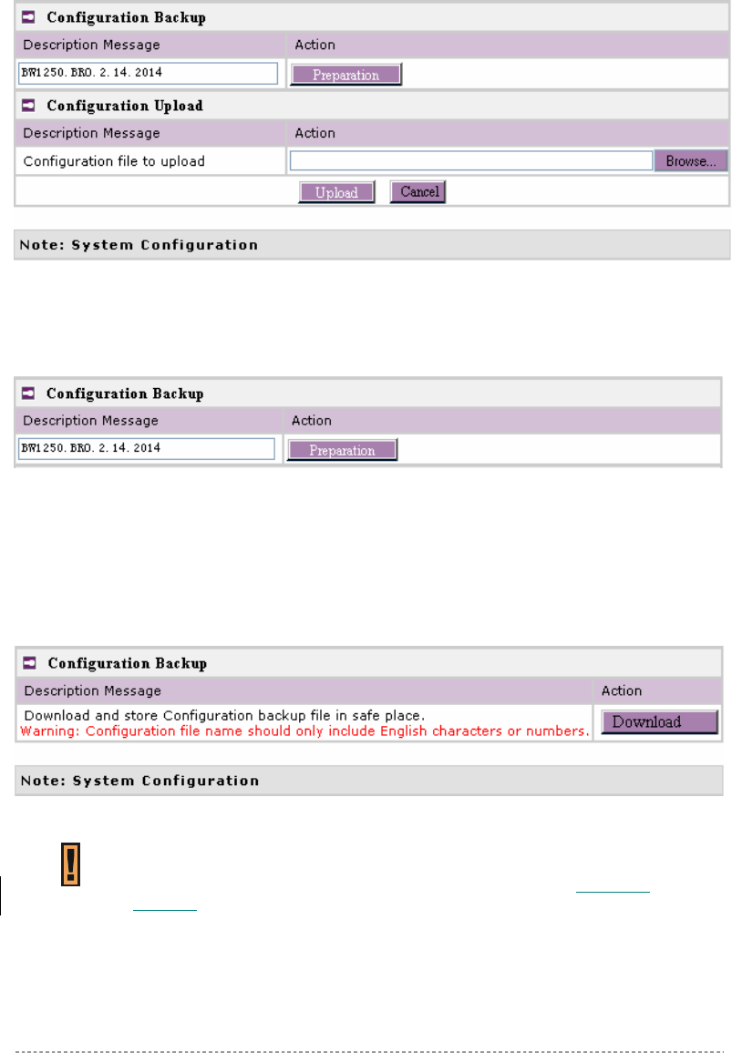
Figure 69 – System Configuration settings
You can save your current device configuration file locally using the Backup menu under the System
| Configuration | Backup menu:
Figure 70 – Backup settings
Such device configuration is saved in the specific format file (.cfg).
Description Message shows the current version of firmware.
Click the Preparation button to start saving the configuration file.
Click the Download button to download current working configuration into your local PC.
Figure 71 – Download system configuration
A configuration file name will be required when you download/save the
configuration file. And please remember the configuration file name should only
include characters or numbers. Otherwise, this configuration file cannot be
uploaded to BW1250.
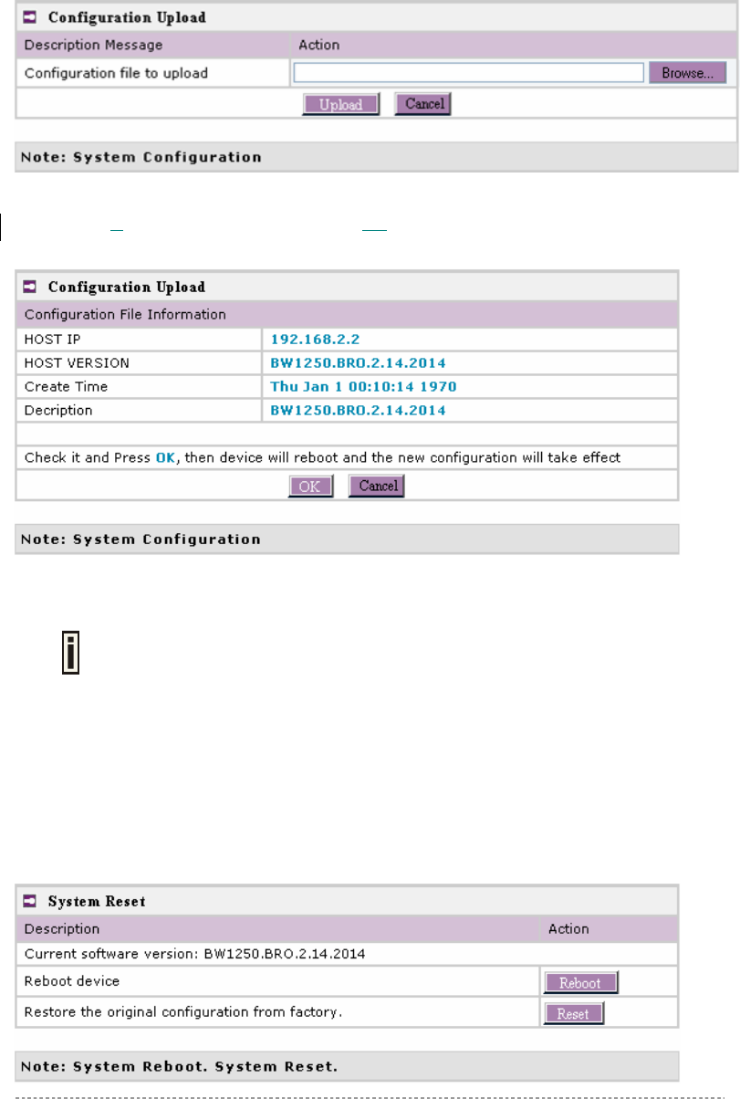
You can upload saved configuration file any time you want to restore this configuration to the device
by using the Browse button Select the configuration file and upload it on the device:
BW1250 Sep. 22, 2006
Browan Page 60 of 68
Figure 72 – Configuration Upload/Restore
Click Upload to upload the specified configuration file and then the similar UI appears
Figure 73 – configuration information
HOST IP – show the IP address in the configuration file that needs to upload.
Please remember this IP address for accessing BW1250 after the configuration file
is uploaded.
HOST VERSION – show the firmware version in the configuration file that needs to upload.
OK – click the button to apply configuration setting to the device.
If everything is right, click OK button for upload/restore.
System | Reset
BW1250 Sep. 22, 2006
Browan Page 61 of 68
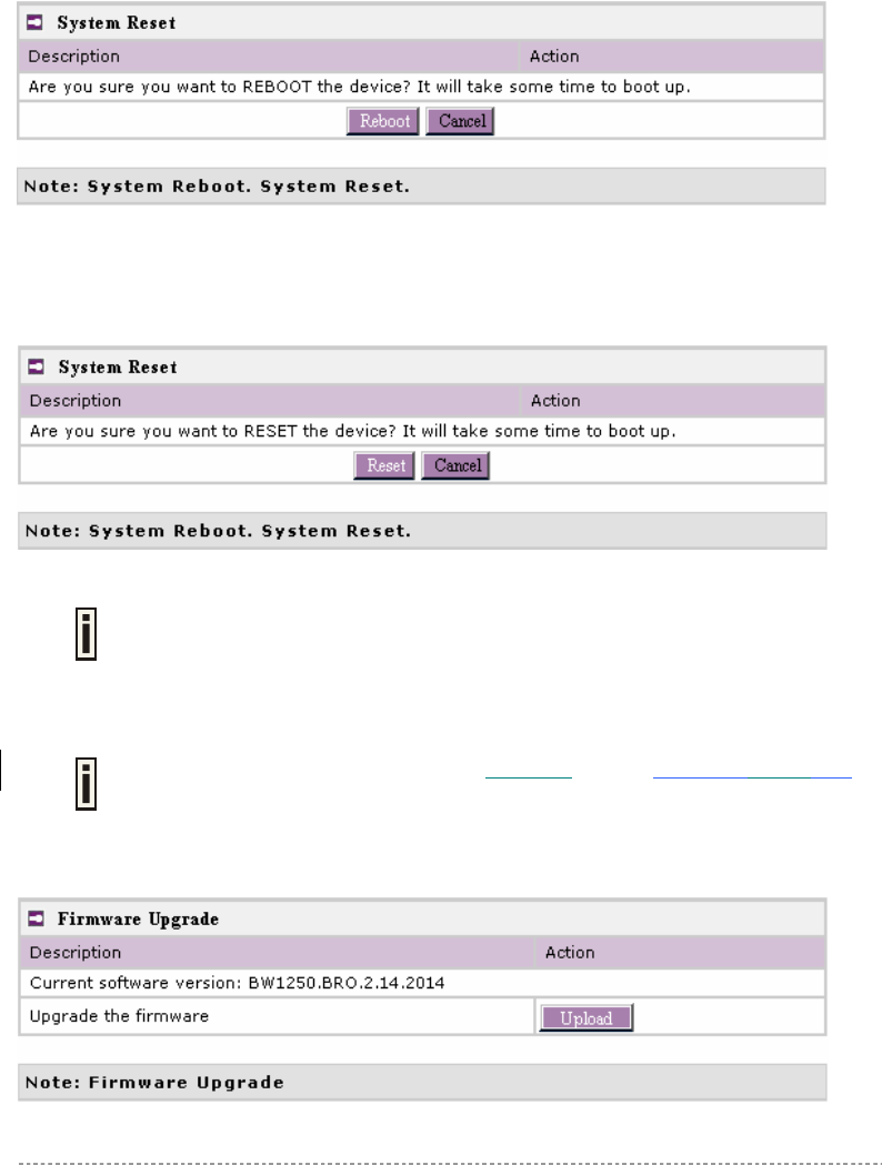
Figure 74 – System Reset setting
Reboot – reboot the device
Reset – reset System to Factory Defaults
To reboot the device, click Reboot and then the below appears to make sure:
Figure 75 – Reboot the device
To reset device to factory defaults, click Reset on Figure 74 – System Reset setting and then the
below appears to make sure:
Figure 76 – Reset the device
Please note that all settings including the administrator settings will be set back to
the factory default when Reset is selected.
System | Upgrade
Check for new product updates at the BROWAN website: http://www.browan.com
Upload – Update your device firmware.
Figure 77 – Firmware Upgrade
BW1250 Sep. 22, 2006
Browan Page 62 of 68
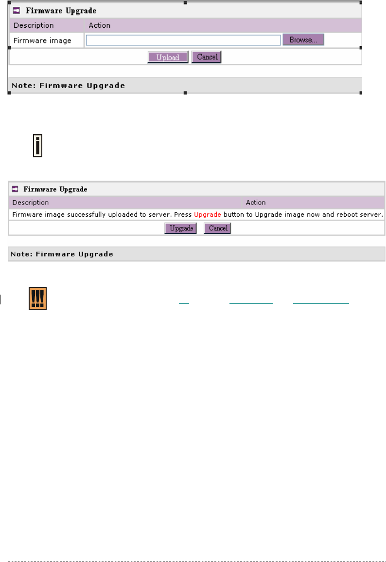
Click the Upload and then the follow appears. Specify the full path to the new firmware image and
click the Upload button:
Figure 78 – Firmware Upgrade
To flash the uploaded firmware image to upgrade the firmware is done by click the Upgrade button.
Please make sure the firmware is correct for BW1250. Otherwise the upgrade will
be failed.
Figure 79 – Device Statistics
Do not switch off and do not disconnect the BW1250 from the power supply during
the firmware update process or the device might crash. It is recommended to use
the Ethernet connection (not wireless) for the firmware update process.

BW1250 Sep. 22, 2006
Browan Page 63 of 68
A) Specification
Wireless
Standard IEEE 802.11b(DSSS), IEEE 802.11g(OFDM) and IEEE 802.11a(OFDM)
Data Rate
802.11a: 54,48,36,24,18,12,9,6Mbps;802.11g:
54,48,36,24,12,9,6,11,5,5,2,1Mbps (auto fall back)
Transmit Power
(RF power)
Max. 19 dBm ± 1.5dBm @ 2.4GHz
Max. 18 dBm ± 1.5dBm @ 5 GHz
(Maximum power will vary by channel, rate and regulatory domain)
Antenna
Encryption WPA/WPA2 TKIP and CCMP-AES , Dynamic/static 64bits and 128bits
WEP
Bridge Up to 8 bridge links
Interface
LAN 10/100Mb Ethernet, auto sensing, RJ-45
Console 1 DB-9 Male (RS232) for serial configuration
Management
Interfaces HTTPs, Secure Telnet(SSHv2), SNMP
Software Update Remote software update via HTTPs
Reset H/W and S/W remote restore factory default
Physical Specification
Dimension 205 mm x 160 mm x 45 mm
Weight 600g
Environment Specification
Temperature Humidity
Operating 0 to +50°C 20% to 90%, non-condensing
Power Supply
POE 48V, IEEE802.3af,Power adapter Jack
Power adaptor External power supply, input: 100-240 VAC, 50-60Hz and output: 12VDC
LEDs
4 LEDs Power, LAN, WLAN1, WLAN2
Warranty
3 years
Package Contents
BW1250 Dual Radio 2.4GHz/5GHz
Access Point
CD-ROM with KickStart utility, User Manuals
(*.pdf)
Warranty Card Ethernet cable 1.5m
Appendix
For 2.4 GHz band: 6dBi; For 5 GHz band: 8dBi

BW1250 Sep. 22, 2006
Browan Page 64 of 68
International power supply USA type Power Cord
EU type Power Cord
Related Products
Controllers: BE9040 SMB Access Controller
Access Points: BW2250 54Mb Dual-bang outdoor
Access Point

BW1250 Sep. 22, 2006
Browan Page 65 of 68
B) Factory Defaults for the BW1250
General Configuration Settings
Administrator Username admin
Administrator Password admin01
Get Community Public
Set Community Private
Network Configuration Settings
IP address (static IP) 192.168.2.2
Subnet mask 255.255.255.0
Gateway 0.0.0.0
Service Configuration Settings
DHCP server Disable
DHCP relay Disable
NTP service Disable
Telnet service Enable
SSH service Enable
Wireless Configuration Settings
RF Card 1(WLAN1)
Default Mode 11g Access Point
Regulatory Domain World
SSID BW1250g
Default channel 11
RTS Threshold 2347 bytes
RF Output Power 19dBm
Authentication Type Open System
MAC ACL Disable
Encryption Off
Security Policy Disable
RF Card 2(WLAN2)
Default Mode 11a Access Point
Regulatory Domain World
SSID BW1250a
Default channel 64
RTS Threshold 2347 bytes
RF Output Power 18dBm
Authentication Type Open System
MAC ACL Disable
Encryption Off
Security Policy Disable

BW1250 Sep. 22, 2006
Browan Page 66 of 68
C) Regulatory Domain/Channels/Power
Channels and Maximum output power for the BW1250 11g radio:
Channels
Identifiers
Frequency in
MHz
USA, Canada
(FCC)
European
Union
(CE/ETSI)
WORLD
(CE&FCC)
Japan
(TELEC)
1 2412 • • • •
2 2417 • • • •
3 2422 • • • •
4 2427 • • • •
5 2432 • • • •
6 2437 • • • •
7 2442 • • • •
8 2447 • • • •
9 2452 • • • •
10 2457 • • • •
11 2462 • • • •
12 2467 — • — •
13 2472 — • — •
14 2484 — — — —
Maximum output Power 19dBm 14dBm 14dBm 14dBm
For channel 1 and channel 11, the maximum output power will be 19dBm in the
case of the setting of domain is FCC.
Channels and Maximum power for the BW1250 11a radio:
Channels
Identifiers
Frequency in
MHz
USA, Canada
(FCC)
European
Union
(CE/ETSI)
WORLD
(CE/FCC)
Japan
(TELEC)
U-NII lower band (5150 – 5250 MHz)
34 5170 — — — •
36 5180 • • • —
38 5190 — — — •
40 5200 • • • —
42 5210 — — — •
44 5220 • • • —
46 5230 — — — •
48 5240 • • • —
Maximum Output Power 14 dBm
17 dBm
15 dBm
15 dBm
U-NII middle band (5250 – 5350 MHz)

BW1250 Sep. 22, 2006
Browan Page 67 of 68
52 5260 -- • • —
56 5280 -- • • —
60 5300 -- • • —
64 5320 -- • • —
Maximum Output Power -- 17 dBm
17 dBm
—
U-NII upper band ( 5725 – 5875 MHz)
149 5745 • — — —
153 5765 • — — —
157 5785 • — — —
161 5805 • — — —
165 5825 — — — —
Maximum Output Power 18dBm 17 dBm 17 dBm —

BW1250 Sep. 22, 2006
Browan Page 68 of 68
D) Location ID and ISO Country Codes
This list states the country names (official short names in English) in alphabetical order as given in
ISO 3166-1 and the corresponding ISO 3166-1-alpha-2 code elements.
It lists 239 official short names and code elements.
Location
ID
Country Location
ID
Country
AF Afghanistan LI Liechtenstein
AL Albania LT Lithuania
DZ Algeria LU Luxembourg
AS American Samoa MO Macao
AD Andorra MK Macedonia, the former Yugoslav
republic of
AO Angola MG Madagascar
AI Anguilla MW Malawi
AQ Antarctica MY Malaysia
AG Antigua and Barbuda MV Maldives
AR Argentina ML Mali
AM Armenia MT Malta
AW Aruba MH Marshall islands
AU Australia MQ Martinique
AT Austria MR Mauritania
AZ Azerbaijan MU Mauritius
BS Bahamas YT Mayotte
BH Bahrain MX Mexico
BD Bangladesh FM Micronesia, federated states of
BB Barbados MD Moldova, republic of
BY Belarus MC Monaco
BE Belgium MN Mongolia
BZ Belize MS Montserrat
BJ Benin MA Morocco
BM Bermuda MZ Mozambique
BT Bhutan MM Myanmar
BO Bolivia NA Namibia
BA Bosnia and Herzegovina NR Nauru
BW Botswana NP Nepal
BV Bouvet island NL Netherlands
BR Brazil AN Netherlands Antilles
IO British Indian ocean territory NC New Caledonia
BN Brunei Darussalam NZ New Zealand
BG Bulgaria NI Nicaragua

BW1250 Sep. 22, 2006
Browan Page 69 of 68
BF Burkina Faso NE Niger
BI Burundi NG Nigeria
KH Cambodia NU Niue
CM Cameroon NF Norfolk island
CA Canada MP Northern Mariana islands
CV Cape Verde NO Norway
KY Cayman islands OM Oman
CF Central African republic PK Pakistan
TD Chad PW Palau
CL Chile PS Palestinian territory, occupied
CN China PA Panama
CX Christmas island PG Papua new guinea
CC Cocos (keeling) islands PY Paraguay
CO Colombia PE Peru
KM Comoros PH Philippines
CG Congo PN Pitcairn
CD Congo, the democratic republic of the
PL Poland
CK Cook islands PT Portugal
CR Costa Rica PR Puerto Rico
CI Côte d'ivoire QA Qatar
HR Croatia RE Réunion
CU Cuba RO Romania
CY Cyprus RU Russian federation
CZ Czech republic RW Rwanda
DK Denmark SH Saint Helena
DJ Djibouti KN Saint Kitts and Nevis
DM Dominica LC Saint Lucia
DO Dominican republic PM Saint Pierre and Miquelon
EC Ecuador VC Saint Vincent and the grenadines
EG Egypt WS Samoa
SV El Salvador SM San Marino
GQ Equatorial guinea ST Sao tome and Principe
ER Eritrea SA Saudi Arabia
EE Estonia SN Senegal
ET Ethiopia SC Seychelles
FK Falkland islands (malvinas) SL Sierra Leone
FO Faroe islands SG Singapore
FJ Fiji SK Slovakia
FI Finland SI Slovenia
FR France SB Solomon islands
GF French Guiana SO Somalia

BW1250 Sep. 22, 2006
Browan Page 70 of 68
PF French Polynesia ZA South Africa
TF French southern territories GS South Georgia and the south
sandwich islands
GA Gabon ES Spain
GM Gambia LK Sri Lanka
GE Georgia SD Sudan
DE Germany SR Suriname
GH Ghana SJ Svalbard and Jan Mayan
GI Gibraltar SZ Swaziland
GR Greece SE Sweden
GL Greenland CH Switzerland
GD Grenada SY Syrian Arab republic
GP Guadeloupe TW Taiwan, province of china
GU Guam TJ Tajikistan
GT Guatemala TZ Tanzania, united republic of
GN Guinea TH Thailand
GW Guinea-Bissau TL Timor-leste
GY Guyana TG Togo
HT Haiti TK Tokelau
HM Heard island and McDonald islands TO Tonga
VA Holy see (Vatican city state) TT Trinidad and Tobago
HN Honduras TN Tunisia
HK Hong Kong TR Turkey
HU Hungary TM Turkmenistan
IS Iceland TC Turks and Caicos islands
IN India TV Tuvalu
ID Indonesia UG Uganda
IR Iran, Islamic republic of UA Ukraine
IQ Iraq AE United Arab emirates
IE Ireland GB United kingdom
IL Israel US United states
IT Italy UM United states minor outlying islands
JM Jamaica UY Uruguay
JP Japan UZ Uzbekistan
JO Jordan VU Vanuatu
KZ Kazakhstan Vatican city state see holy see
KE Kenya VE Venezuela
KI Kiribati VN Viet nam
KP Korea, democratic people's republic
of
VG Virgin islands, British
KR Korea, republic of VI Virgin islands, u.s.
KW Kuwait WF Wallis and Futuna

BW1250 Sep. 22, 2006
Browan Page 71 of 68
KG Kyrgyzstan EH Western Sahara
LA Lao people's democratic republic YE Yemen
LV Latvia YU Yugoslavia
LB Lebanon
Zaire see Congo, the democratic
republic of the
LS Lesotho ZM Zambia
LR Liberia ZW Zimbabwe
LY Libyan Arab Jamahiriya