GemTek Technology AP930621G 54 Mb Hotspot-in-a-Box User Manual Title
Gemtek Technology Co., Ltd. 54 Mb Hotspot-in-a-Box Title
Contents
- 1. User Manual Part 1
- 2. Users Manual Part 2
User Manual Part 1

Federal Communication Commission Interference Statement
This equipment has been tested and found to comply with the limits for a Class B digital device,
pursuant to Part 15 of the FCC Rules. These limits are designed to provide reasonable
protection against harmful interference in a residential installation. This equipment generates,
uses and can radiate radio frequency energy and, if not installed and used in accordance with
the instructions, may cause harmful interference to radio communications. However, there is no
guarantee that interference will not occur in a particular installation. If this equipment does cause
harmful interference to radio or television reception, which can be determined by turning the
equipment off and on, the user is encouraged to try to correct the interference by one of the
following measures:
- Reorient or relocate the receiving antenna.
- Increase the separation between the equipment and receiver.
- Connect the equipment into an outlet on a circuit different from that to which the receiver is
connected.
- Consult the dealer or an experienced radio/TV technician for help.
FCC Caution: To assure continued compliance, any changes or modifications not expressly
approved by the party responsible for compliance could void the user’s authority to operate this
equipment.
This device complies with Part 15 of the FCC Rules. Operation is subject to the following two
conditions: (1) This device may not cause harmful interference, and (2) this device must accept
any interference received, including interference that may cause undesired operation.
IMPORTANT NOTE:
FCC Radiation Exposure Statement:
This equipment complies with FCC radiation exposure limits set forth for an uncontrolled
environment. This equipment should be installed and operated with minimum distance 20cm
between the radiator & your body.
This transmitter must not be co-located or operating in conjunction with any other antenna or
transmitter.
Gemtek Systems declares that P-560 ( FCC ID: MXF-AP930621G ) is limited in CH1~CH11 by specified
firmware controlled in U.S.A.

Copyright
© 2002-2004 Gemtek Systems Holding BV.
This user’s guide and the software described in it are copyrighted with all rights reserved. No part of
this publication may be reproduced, transmitted, transcribed, stored in a retrieval system, or translated
into any language in any form by any means without the written permission of Gemtek Systems
Holding BV.
Notice
Gemtek Systems reserves the right to change specifications without prior notice.
While the information in this manual has been compiled with great care, it may not be deemed an
assurance of product characteristics. Gemtek Systems shall be liable only to the degree specified in
the terms of sale and delivery.
The reproduction and distribution of the documentation and software supplied with this product and
the use of its contents is subject to written authorization from Gemtek Systems.
Trademarks
The product described in this book is a licensed product of Gemtek Systems Holding BV.
Microsoft, Windows 95, Windows 98, Windows Millennium, Windows NT, Windows 2000, Windows
XP, and MS-DOS are registered trademarks of the Microsoft Corporation.
Novell is a registered trademark of Novell, Inc.
MacOS is a registered trademark of Apple Computer, Inc.
Java is a trademark of Sun Microsystems, Inc.
Wi-Fi is a registered trademark of Wi-Fi Alliance.
All other brand and product names are trademarks or registered trademarks of their respective
holders.
Gemtek Systems Page 3

User’s Guide Contents
Contents
Copyright ............................................................................................................................................. 3
Notice ..................................................................................................................................................3
Trademarks .........................................................................................................................................3
CONTENTS ............................................................................................................................................ 4
ABOUT THIS GUIDE.............................................................................................................................. 7
Purpose ...............................................................................................................................................7
Prerequisite Skills and Knowledge...................................................................................................... 7
Conventions Used in this Document ...................................................................................................7
Help Us to Improve this Document! .................................................................................................... 7
Gemtek Systems Technical Support................................................................................................... 7
CHAPTER 1 – INTRODUCTION ............................................................................................................ 8
Product Overview ................................................................................................................................8
Management Options ..........................................................................................................................9
Access Controller Features .................................................................................................................9
INSTALLATION.................................................................................................................................... 11
The Product Package........................................................................................................................11
Hardware Introduction .......................................................................................................................12
General Overview ..........................................................................................................................12
Back Panel.....................................................................................................................................13
LEDs ..............................................................................................................................................13
Connectors.....................................................................................................................................14
Connecting the Access Controller.....................................................................................................15
Initialization........................................................................................................................................16
Software Introduction: KickStart ....................................................................................................16
Access Your P-560 ........................................................................................................................16
Step by Step Setup ...........................................................................................................................19
CHAPTER 3 – UNIVERSAL ADDRESS TRANSLATION ................................................................... 22
CHAPTER 4 – USER PAGES .............................................................................................................. 24
User Pages Overview........................................................................................................................25
Welcome Page...............................................................................................................................25
Login Page.....................................................................................................................................25
Logout Page...................................................................................................................................26
Help Page ......................................................................................................................................27
Unauthorized Page ........................................................................................................................27
Changing User Pages .......................................................................................................................28
Example for External Pages ..........................................................................................................28
Example for Internal Pages ...........................................................................................................30
Extended UAM .................................................................................................................................. 33
Parameters Sent to WAS...............................................................................................................35
CHAPTER 5 – COMMAND LINE INTERFACE.................................................................................... 39
Introduction........................................................................................................................................39
Get Connection to CLI.......................................................................................................................39
Telnet Connection..........................................................................................................................39
SSH Connection ............................................................................................................................40
Login..................................................................................................................................................40
Connection ........................................................................................................................................40
Gemtek Systems Page 4

User’s Guide Contents
Network .............................................................................................................................................41
Wireless.............................................................................................................................................43
User ...................................................................................................................................................44
Status ................................................................................................................................................45
System...............................................................................................................................................45
Telnet.................................................................................................................................................46
Reboot...............................................................................................................................................46
Reset .................................................................................................................................................46
Exit.....................................................................................................................................................46
CHAPTER 6 – SNMP MANAGEMENT ................................................................................................47
Introduction........................................................................................................................................47
SNMP Versions .................................................................................................................................47
SNMP Agent......................................................................................................................................48
SNMP Community Strings.................................................................................................................48
Use SNMP to Access MIB.................................................................................................................49
Gemtek Private MIB ..........................................................................................................................49
CHAPTER 7 – REFERENCE MANUAL............................................................................................... 50
Web Interface .................................................................................................................................... 50
Network Interface ..............................................................................................................................52
Network Interface | Configuration | Interface Configuration...........................................................52
Network Interface | Configuration | VLAN......................................................................................54
Network Interface | Configuration | Route......................................................................................55
Network Interface | Configuration | Port Forwarding .....................................................................56
Network Interface | Configuration | Management Subnet..............................................................57
Network Interface | DNS ................................................................................................................58
Network Interface | DHCP .............................................................................................................59
Network Interface | RADIUS ..........................................................................................................62
Network Interface | RADIUS | RADIUS Settings ...........................................................................63
Network Interface | RADIUS | RADIUS Servers............................................................................65
Network Interface | RADIUS | WISP..............................................................................................67
Network Interface | RADIUS | Proxy..............................................................................................67
Network Interface | RADIUS | Accounting Backup ........................................................................69
Network Interface | Tunnels...........................................................................................................70
Network Interface | Tunnels | PPPoE/PPTP/GRE.........................................................................70
Network Interface | Tunnels | PPTP Client for VPN ......................................................................71
Network Interface | Tunnels | GRE Client for VPN ........................................................................72
Network Interface | Wireless..........................................................................................................75
Network Interface | Wireless | Basic ..............................................................................................75
Network Interface | Wireless | Advanced.......................................................................................77
Network Interface | Wireless | Security..........................................................................................77
Network Interface | Wireless | ACL................................................................................................78
Network Interface | Wireless | WDS ..............................................................................................80
User Interface....................................................................................................................................82
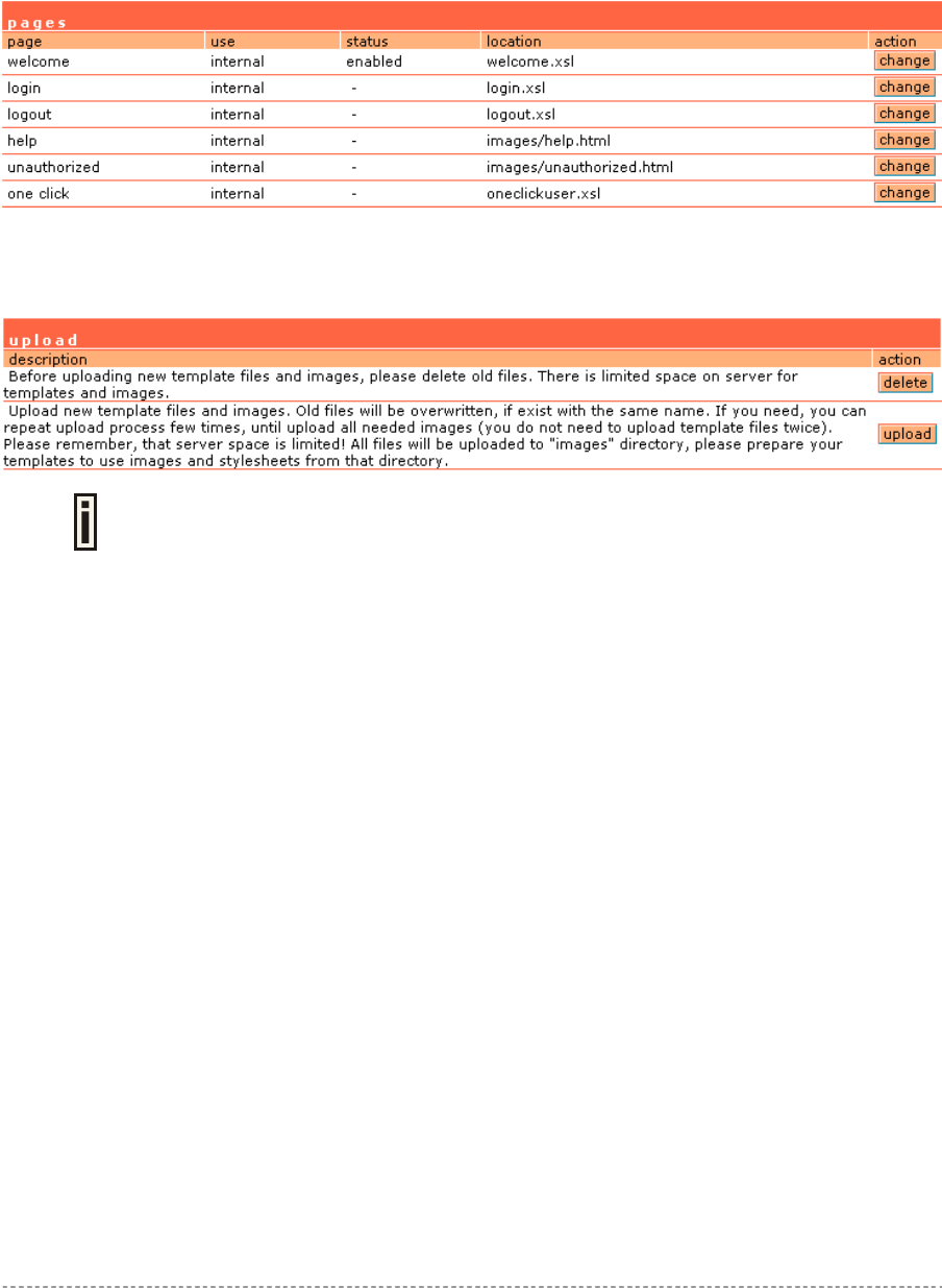
User Interface | Configuration | Pages...........................................................................................82
User Interface | Configuration | Upload .........................................................................................83
User Interface | Configuration | Headers .......................................................................................83
User Interface | Configuration | Remote Authentication ................................................................84
User Interface | Configuration | One-Click Roaming .....................................................................85
User Interface | Administrator ........................................................................................................86
User Interface | Start Page ............................................................................................................87
User Interface | Walled Garden .....................................................................................................87
User Interface | Web Proxy............................................................................................................89
System...............................................................................................................................................90
System | Configuration | Syslog.....................................................................................................90
System | Configuration | Trace System .........................................................................................91
System | Configuration | Clock ......................................................................................................91
Gemtek Systems Page 5

User’s Guide Contents
System | Configuration | NTP ........................................................................................................92
System | Configuration | Certificate ...............................................................................................93
System | Configuration | Save and Restore...................................................................................94
System | Configuration | Pronto.....................................................................................................95
System | Access | Access Control .................................................................................................96
System | Access | Telnet ...............................................................................................................97
System | Access | AAA ..................................................................................................................98
System | Access | UAT ..................................................................................................................99
System | Access | Isolation ..........................................................................................................100
System | Access | NAV ................................................................................................................100
System | Access | SNMP .............................................................................................................101
System | Status............................................................................................................................104
System | Reset.............................................................................................................................107
System | Update ..........................................................................................................................108
Connection ......................................................................................................................................110
Connection | Users ......................................................................................................................110
Connection | E-mail Redirection ..................................................................................................112
Connection | Station Supervision.................................................................................................112
APPENDIX..........................................................................................................................................113
A) Access Controller Specification ..................................................................................................113
Technical Data.............................................................................................................................113
B) Factory Defaults for the Access Controller .................................................................................115
C) Regulatory Domain/Channels ....................................................................................................122
D) CLI Commands and Parameters................................................................................................ 123
Network Commands ....................................................................................................................123
Wireless Commands....................................................................................................................127
User Commands..........................................................................................................................128
System Commands .....................................................................................................................129
Status Commands .......................................................................................................................131
Connection Commands ...............................................................................................................131
E) Standard RADIUS Attributes ......................................................................................................133
Vendor Specific Attributes ...........................................................................................................134
F) Location ID and ISO Country Codes ..........................................................................................136
G) User Pages Templates Syntax...................................................................................................140
GLOSSARY ........................................................................................................................................145
INDEX .................................................................................................................................................150
Gemtek Systems Page 6
User’s Guide About this Guide
About this Guide
Purpose
This document provides information and procedures on hardware installation, setup, configuration,
and management of the Gemtek Systems high performance 56Mb Hotspot-in-a-Box model P-560.
The P-560 is a highly integrated Access Controller for public access areas. We will call it AC later in
the manual.
Prerequisite Skills and Knowledge
To use this document effectively, you should have a working knowledge of Local Area Networking
(LAN) concepts and wireless Internet access infrastructures. In addition, you should be familiar with
the following:
Hardware installers should have a working knowledge of basic electronics and mechanical
assembly, and should understand related local building codes.
Network administrators should have a solid understanding of software installation procedures for
network operating systems under Microsoft Windows 95, 98, Millennium, 2000, NT, and Windows
XP and general networking operations and troubleshooting knowledge.
Conventions Used in this Document
The following typographic conventions and symbols are used throughout this document:
Very important information. Failure to observe this may result in damage.
Important information that should be observed.
Additional information that may be helpful but which is not required.
bold Menu commands, buttons and input fields are displayed in bold
code File names, directory names, form names, and system-generated output
such as error messages are displayed in constant-width type
<value> Placeholder for certain values, e.g. user inputs
[value] Input field format, limitations, and/or restrictions.
Help Us to Improve this Document!
If you should encounter mistakes in this document or want to provide comments to improve the
manual please send e-mail directly to:
manuals@gemtek-systems.com
Gemtek Systems Technical Support
If you encounter problems when installing or using this product, please consult the Gemtek Systems
website at www.gemtek-systems.com for:
Direct contact to the Gemtek Systems support centers.
Frequently Asked Questions (FAQ).
Download area for the latest software, user documentation and product updates.
Gemtek Systems Page 7

User’s Guide Chapter 1 – Introduction
Chapter 1 – Introduction
Thank you for choosing the Gemtek Systems 54 Mb High Performance Hotspot-in-a-Box.
The Gemtek Systems P-560 is a high performance and highly integrated Access Controller for public
access networks. It combines a high-speed wireless LAN Access Point, an IP Router, a 4-port LAN
Switch and a complete Access Controller for Wi-Fi Hotspots in one box. One single P-560 can serve
up to 100 simultaneous users (depending on SW license), takes control over authentication,
accounting and routing to the Internet as well as to the operator’s central.
Product Overview
Scalable With Customer Needs
The P-560 Access Controller can be ordered with three different software licenses allowing operators
to extend functionality as their business grows. The basic “Bronze” license already supports all
required functions to operate a public access network for up to 20 simultaneous subscribers. The
“Silver” license is an upgrade for unlimited users (up to 100) and multiple WISP support whereas the
“Gold” software enables wireless LAN switching and remote AP management to the network.
Authentication, Authorization & Accounting
The P-560 supports multiple secure authentication methods from standard web browser login
(Universal Access Method), MAC authentication, to 802.1x/EAP with passwords, certificates or SIM
cards. The integrated real-time accounting system is based on standard RADIUS/EAP and supports
various billing plans from prepaid, pay-per-time, per-volume, per-use or flat rate. Integration into
existing OSS/BSS systems can be done with ease.
Service Differentiation
The integrated Web server of the P-560 allows flexible interaction with common web application
servers, facilitating the provisioning of differentiated services with bandwidth management, location
based and personalized services. Inter-Provider roaming and multi-OSS support is guaranteed by the
persistent usage of standardized protocols and interfaces like RADIUS, HTTPS and XML. As all
Gemtek Systems Access Controllers P-560 is compliant with the recommendations of the Wi-Fi
Alliance WISP roaming group.
Remote Control
The P-560 Hotspot-in-a-Box is placed at the edge of a broadband access network and allows
operators to provide cost effective public Wi-Fi services, by managing per user access control, device
configuration, and radio performance centrally from the operations centre. HTTPs, telnet, SSH or
SNMP over VPN can be used for secure remote management.
Privacy
P-560 supports different levels of security and data encryption. Client stations can be separated on
link layer (Layer2 User Isolation), preventing intruders from accessing the hard discs of other users.
User credentials (passwords) are protected by SSL or EAP-based authentication methods. User traffic
can be encrypted either by VPNs (pass-through) by Wi-Fi Protected Access (WPA). Operators and
service providers can make use of the integrated VPN/tunneling protocols to protect AAA and
management traffic.
Gemtek Systems Page 8

User’s Guide Chapter 1 – Introduction
Management Options
You can use the Access Controller management systems through the following interfaces:
Web-browser interface
Command Line interface (CLI)
Simple Network Management Protocol (SNMP v1, v2, v3)
The AC management system pages are organized the same way for the web-browser interface and
the CLI. This user manual provides detailed description of each management option.
Access Controller Features
WLAN
802.11b+g compliant, 1-54Mbps with auto-fallback
Wi-Fi compliant
Concurrent 802.11b and 802.11g access
WDS support (concurrent bridge and AP mode)
WPA support
Antenna diversity
SMA connectors for external antennas
Adjustable RF output power
High receiver sensivity (up to -90 dBm@1Mbps, 8%PER)
AAA
Multiple authentication methods: UAM, 802.1x/EAP, RADIUS, MAC, Smart Client (e.g. iPass)
WISPr compliant
Internal and external accounting backups
Internal or external web server
Remote user login, logout, session status control via https/XML
AAA proxy server (for simultaneous EAP and UAM)
Per user bandwidth management
Web proxy support
IP Router and IP address management
Static IP routing table
NAT/NAPT (IP masquerading)
Port-forwarding
Transparent VPN client pass-through (PPTP, IPsec ESP)
Selective source routing (in preparation)
PPPoE client
PPTP client
DHCP server, relay gateway (suboptions), DHCP client
Multiple IP pools per user group
UAT (Universal Address Translation)
SMTP redirection (e-mail)
VPN
PPTP VPN client, max. 16 tunnels
MPPE (40, 56, 128 bit encryption)
GRE VPN client, max. 16 tunnels
IPsec client (in preparation)
Gemtek Systems Page 9

User’s Guide Chapter 1 – Introduction
LAN switch
Managed 4-port switch 10/100Mb, auto-sensing
802.1q/p tagged VLAN support (in preparation)
Management
Secure management via https, SSH, SNMP
SNMP proxy
SNMPv3 (incl. authentication and encryption)
Management subnet for remote AP and switch management
Remote firmware update
Gemtek Systems Page 10

User’s Guide Installation
Installation
This chapter provides installation instructions for the hardware and software components of the
Access Controller P-560. It also includes the procedures for the following tasks:
Hardware Introduction (LEDs, Connectors)
Connecting the Access Controller
First Configuration
Step-by-Step Setup
The Product Package
The Access Controller comes with the following:
54Mb High Performance Hotspot-in-a-Box (model: P-560)
Detachable Antennas (SMA type, 2 units)
Power Cord for EU (1 unit)
Power Adapter (5V, 2.5A, 1 unit)
Ethernet Patch Cable (STP, 1.8 m length, 2 units)
Mounting Kit, included tool to remove AP from wall mounting (1 unit)
Installation CD containing:
P-560 User Guide in PDF format
User Pages Templates Samples
KickStart Utility
Product Firmware
Release Notes
Adobe Acrobat Readers
Printed Warranty Note
If any of these items are missing or damaged, please contact your reseller or
Gemtek System sales representative.
Gemtek Systems Page 11
User’s Guide Installation
Hardware Introduction
General Overview
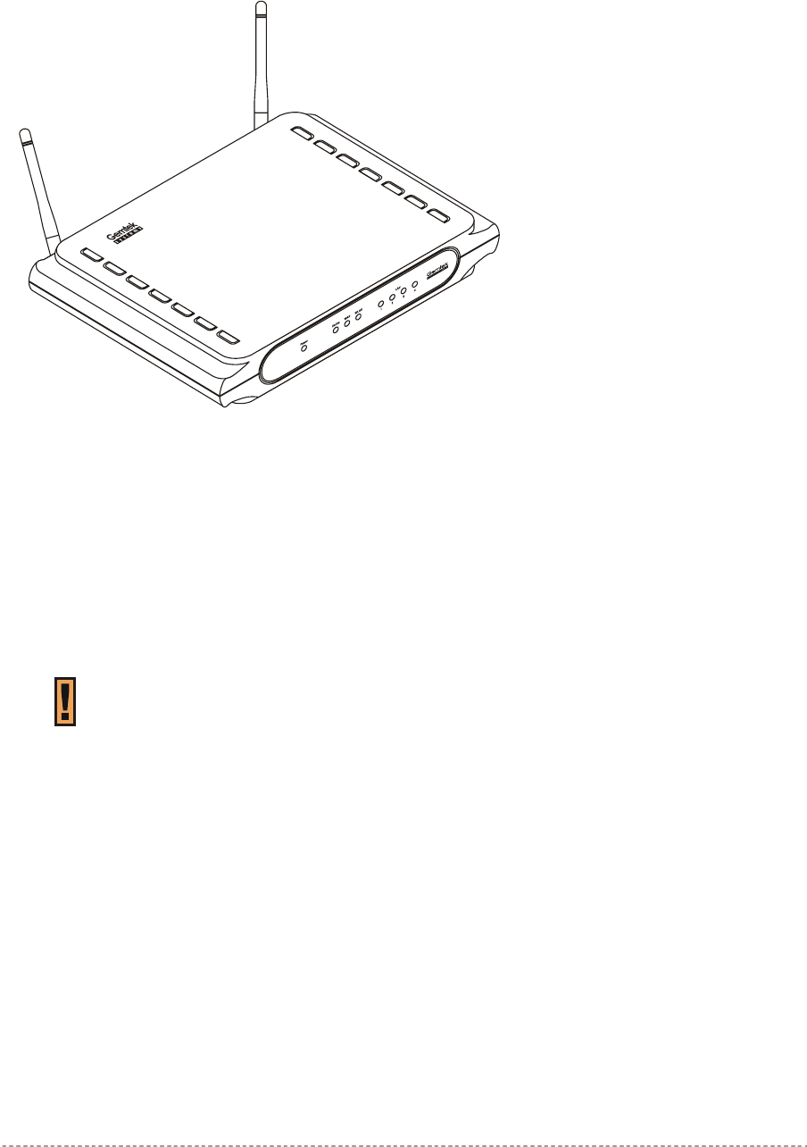
Figure 1 – P-560 Access Controller General View
The front panel of the Access Controller contains:
A series of indicator lights (LEDs) that help describe the state of various networking and
connection operations.
The reverse panel of the Access Controller contains:
Connectors which enable you to make different network connections for the controller
Reset button enables you to reboot or reset the device configuration to the factory defaults
Press the Reset button for less than 5 seconds to reboot the controller.
Press the Reset button for more than 5 seconds to set the controller to factory
defaults.
Gemtek Systems Page 12
User’s Guide Installation
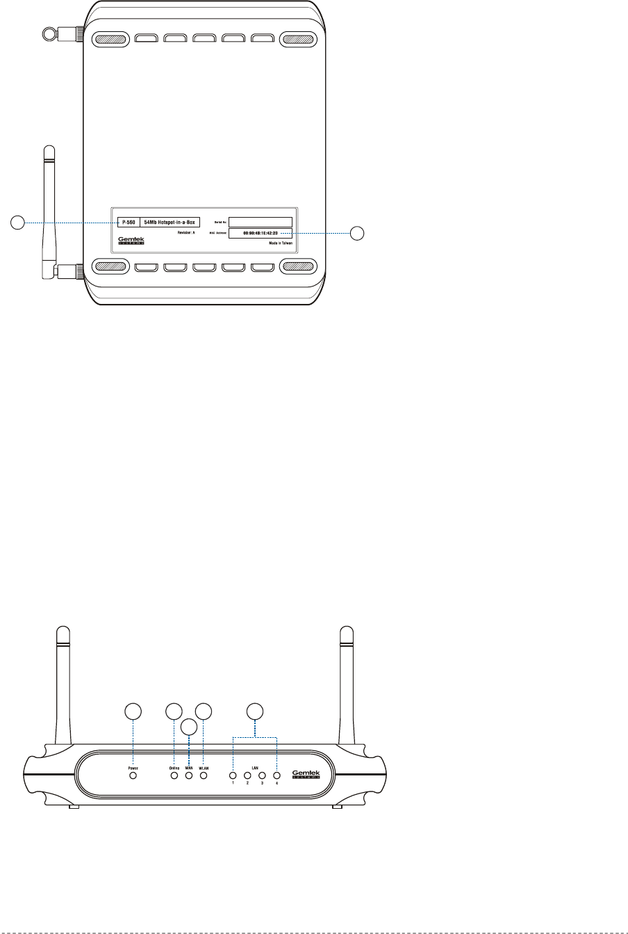
Back Panel
1
2
Figure 2 – Back Panel of the P-560
The back panel of the Access Controller contains:
Model and device name (see item 1 in figure above). The official device name is 54Mb Hotspot-
in-a-Box, model P-560.
MAC address of the device. The label (item 2 in figure above) shows the WLAN interface MAC
address of the device. You can determine the WAN and LAN interfaces’ MAC addresses by a
simple calculation:
LAN interface MAC = WLAN MAC + 1
WAN interface MAC = WLAN MAC + 2
LEDs
The Access Controller has several LEDs located on the front panel:
1 2
3
4 5
Figure 3 – LEDs of the P-560
Gemtek Systems Page 13
User’s Guide Installation
The various states of the LEDs indicate different networking and connection operations as follows:
Item LED Color Status Indication
On P-560 is active/working Green
Blink P-560 is booting
1 Power
Orange On Writing to FLASH memory
On PPPoE/PPTP/GRE tunnel for DSL is
active on P-560
2 Online Green
Off No active PPPoE/PPTP/GRE tunnel
for DSL on P-560
3 WAN Orange On WAN active/working
4 WLAN Orange On WLAN active/working
Green On 100 Mbps network connection exists 5 LAN (1, 2, 3, 4)
Orange On 10 Mbps network connection exists
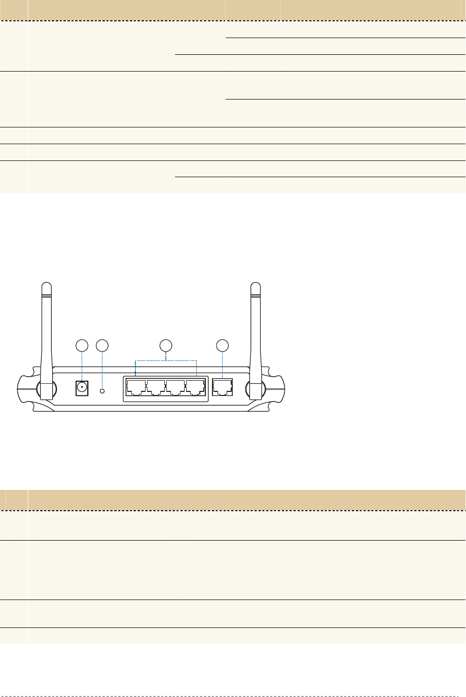
Connectors
The Access Controller has several connectors on the rear panel:
Power
Reset Internet
LAN 4321
1 2 3 4
Figure 4 – Connectors
Descriptions of the connectors are given in the following table:
Item Connector Description
1 Power For power supply
2 Reset Reboot or reset to factory defaults.
Press the reset button for less than 5 seconds to reboot the
controller. Press the reset button for more than 5 seconds to
set the controller to factory defaults
3 LAN (1, 2, 3, 4) For enterprise applications use this port to connect your
company LAN, Intranet or to hotspot access points
4 Internet For Internet connection
Gemtek Systems Page 14

User’s Guide Installation
Connecting the Access Controller
Use the following procedure to prepare your network connection to the Access Controller.
Use the enclosed power adapter and power cord for power supply of your Access
Controller.
Step 1 Place the Access Controller on a flat work surface.
Step 2 Connect one Ethernet patch cable to the LAN port of the Access Controller and to
a free hub port on your local network.
Step 3 Connect one Ethernet patch cable to the WAN port of the Access Controller and to
an Ethernet port of a broadband Internet modem or router.
Step 4 Connect the power cord to your power adapter. Connect power adapter to the
Access Controller.
Step 6 Wait 30 seconds until the boot process is finished and check to ensure that at least
the following LEDs are ON:
Status LED (steady On)
WAN LED
LAN LED
WLAN link LED
Gemtek Systems Page 15

User’s Guide Installation
Initialization
There are two choices for the first web browser connection to your Access Controller: either you enter
your access controller's IP address and subnet (default networks settings) into the browser or you
launch the KickStart utility that is provided with your product CD.
The default network settings for your new access controller are:
LAN port: IP 192.168.3.1 subnet 255.255.255.0
WAN port: IP 192.168.2.66 subnet 255.255.255.0
WLAN port: IP 192.168.4.1 subnet 255.255.255.0
DHCP Server: enabled for LAN and WLAN ports
For other management methods: SNMP and command line interface (CLI) please
refer to their respective chapters.
Software Introduction: KickStart
The Gemtek Systems KickStart is a software utility that is included on the Installation CD.
The utility automatically detects access points and access controllers installed on your network,
regardless of its host IP address and lets you configure each unit’s IP settings. The feature list for the
KickStart utility is listed below:
Scanning your subnet for all connected APs, ACs
Quick access to your AC via HTTPS, telnet, SSH
Setting new IP address of your AC
Reset to factory default settings
Default access (in case of lost administrator password)
Firmware updates
To install the KickStart utility insert the Installation CD into your CD-ROM drive. Find and install the
utility from the product CD into the computer.
If the Installation CD does not start automatically, please run “autorun.exe”
manually from the root directory of the installation CD.
Access Your P-560
There are two choices for the first Web browser connection to your access point:
Use the Web browser.
Launch the KickStart utility that is provided with your product CD.
If first method is preferred follow these instructions:
Step 1 Configure your PC with a static IP address on the 192.168.2.0 subnet with mask
255.255.255.0. Connect the P-560 in to the same physical network as your PC. Open
the Web browser and type the default IP address of the P-560:
https://192.168.2.66/a.rg
Step 2 Enter the P-560 administrator login details to access the Web management.
Gemtek Systems Page 16
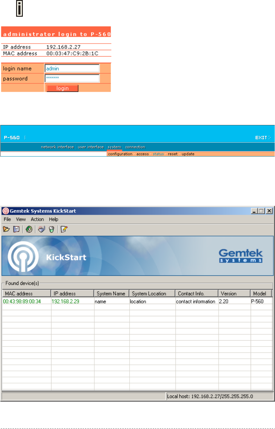
User’s Guide Installation
The default administrator log on settings for all access point interfaces are:
User Name: admin
Password: admin01
Step 3 After successful administrator log on you will see the main page of the access
controller’s Web interface:
If second method is prefered follow the instuctions:
Step 1 Install the KickStart utility from the Installation CD. Click Start > Programs > GSI
> KickStart to launch the application. If the P-560 device is connected to your
network, the utility will automatically find your AC:
Gemtek Systems Page 17
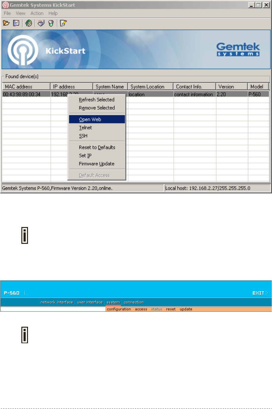
User’s Guide Installation
Step 2 Select your controller and right click. Select Open WEB item to launch the web
management interface through the secure https connection:
Step 3 Enter the Access Controller administrator login settings to access the web
management interface.
The default administrator log on settings for all controller interfaces are:
User name: admin
Password: admin01
Step 4 After successful administrator log on you will see the controller web interface. The
controller system statistics page is displayed by default:
If you cannot connect to the device via your web browser because of TCP/IP mis-
configuration, you can reset the product to the factory default. Press the reset
button for more than 5 seconds.
Now you are enabled to perform the initial controller configuration. Follow the next section for step-by-
step setup instruction to configure the device according to your needs.
Gemtek Systems Page 18
User’s Guide Installation
Step by Step Setup
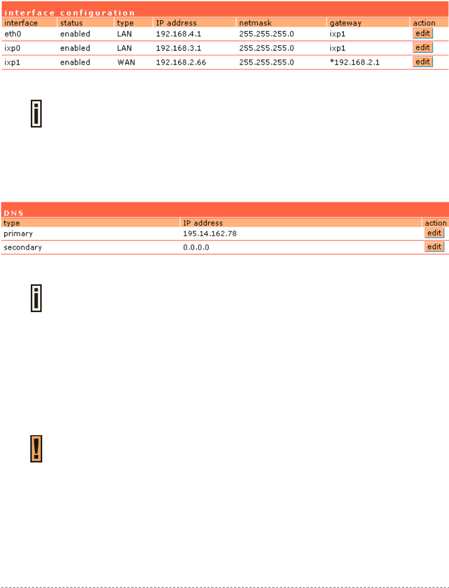
Step 1. Interface Set-Up
In the network interface | configuration menu you can set the TCP/IP settings. Eth0 is pre-
configured as the WLAN port of your Access Controller, Ixp1 is the WAN port, and Ixp0 is the LAN
port. You can modify these settings according to your local network requirements. Make sure that IP
subnets do not overlap.
Figure 5 – Interface Configuration Settings
If DHCP client, PPPoE, or PPTP is selected as a dial-up protocol for the WAN
interface the WAN settings of this table will be overwritten by the values retrieved
from the Internet Provider.
Step 2. DNS Set-Up
In the network interface | DNS menu you can specify your local domain name server or enter the
DNS server provided by your ISP (Internet Service Provider).
Figure 6 – DNS Redirection
DNS is set automatically if provided by the ISP dynamically via DHCP, PPPoE or
PPTP.
Step 3. IP Address Management
For automatic IP assignments to client stations, set the DHCP settings in the network interface |
DHCP menu according to your TCP/IP configuration from step 1. Only use address ranges within the
corresponding IP subnet of the LAN interface. In addition you can switch on the Universal Address
Translation function in the system | access | UAT menu. With UAT users do not need to change their
local TCP/IP settings to log on to the Access Controller. The Access Controller will translate fixed IP
numbers used in private networks transparently for the user.
Please refer to Chapter 3 – Universal Address Translation for further details to
avoid IP conflicts.
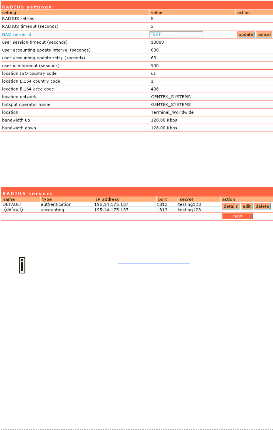
Step 4. RADIUS Set-Up
In the network interface | RADIUS settings menu you can first define the local settings of the
integrated RADIUS client of the Access Controller. For example you can modify timeouts and the
NAS server ID (name of the RADIUS client):
Gemtek Systems Page 19
User’s Guide Installation
Figure 7 – RADIUS Settings
On the second page: network interface | RADIUS servers you can specify up to 32 different
RADIUS servers for authentication and accounting (see Figure 8 – RADIUS Servers). The first line of
this table is the default server (can be configured as default). Thus, if a user cannot be associated to
any specific service provider by his login name, the Access Controller will send authentication and
accounting messages to the first RADIUS server on the list.
Figure 8 – RADIUS Servers
Make sure that the RADIUS server is up and running and is able to receive authentication requests
from the Access Controller.
On the download pages at www.gemtek-systems.com you will find quick installation
guides for common RADIUS servers.
Step 5. Welcome/Login/Start pages
The most popular authentication method for public users is the UAM (Universal Access Method).
UAM can be enabled using the system | access | AAA menu. With UAM users can log-on to the
Access Controller using their web browser. As an operator of a wireless access service you can
provide a custom set of web pages to your subscribers.
welcome page (default = on) - the first page that is presented when users start their web
browser.
login page (default = on) – the page containing the log-on fields for user name and
password. This page is presented as default when the welcome page is disabled.
logout page (default = on) - the page that pops up after successful authentication. It includes
information about the online session such as online time and transferred data.
help page (default = on) - the page with online help information for log-on.
start page (default = on) - the default-page that will be presented to the user after successful
log-on.
unauthorized page (default = on) - the page which appears if web login method is disabled.
Gemtek Systems Page 20
User’s Guide Installation
The default user login page looks like the picture below:
Figure 9 – Example of a Simple Login Page
You have full flexibility to modify and adapt all these pages to your needs and personal designs. For
initial set up and testing we recommend you use the default configuration, which will present a simple
login window with input fields for user name and password.
Enter any start page you like in the user interface | start page menu. In addition you can define a
number of free web sites in the walled garden table on the user interface menu.
For more information on how to build your own user pages please refer to Chapter
4 – User Pages.
Step 6. Change Administrator Password
Before saving your initial configuration don’t forget to change the administrator password in the user
interface | administrator menu.
Step 7. E-mail Redirection
If you have a SMTP mail server available for your subscribers enter its IP address and SMTP port
number in the connection menu under the item e-mail redirection. All outgoing e-mail passing
through the Access Controller will be redirected to this server.
Step 8. Save Configuration and Restart
Make sure you have saved your changes from each of the first seven steps and then press the
restart button on the lower side of the web management screen. After 10-15 seconds you can re-
load the admin pages or start to log on to the Access Controller as a user.
Users connected to the LAN port of the Access Controller can type in any URL in their browser and
they will be redirected to your defined welcome (if enabled) and login pages. Administrators can
monitor connected users via the connection | users menu.
Gemtek Systems Page 21
User’s Guide Chapter 3 – Universal Address Translation
Universal Address Translation (UAT) allows Hotspot operators to offer true Plug&Play access for
their subscribers.
With UAT enabled, the Access Controller will automatically and transparently translate fixed IP
settings (IP address, gateway, DNS, proxy server) on a user’s PC enabling him to connect to the
broadband Internet service.
Without UAT public access, subscribers are forced to switch their TCP/IP settings to DHCP
(automatic IP address assignment), potentially losing any fixed IP address settings they previously
entered.
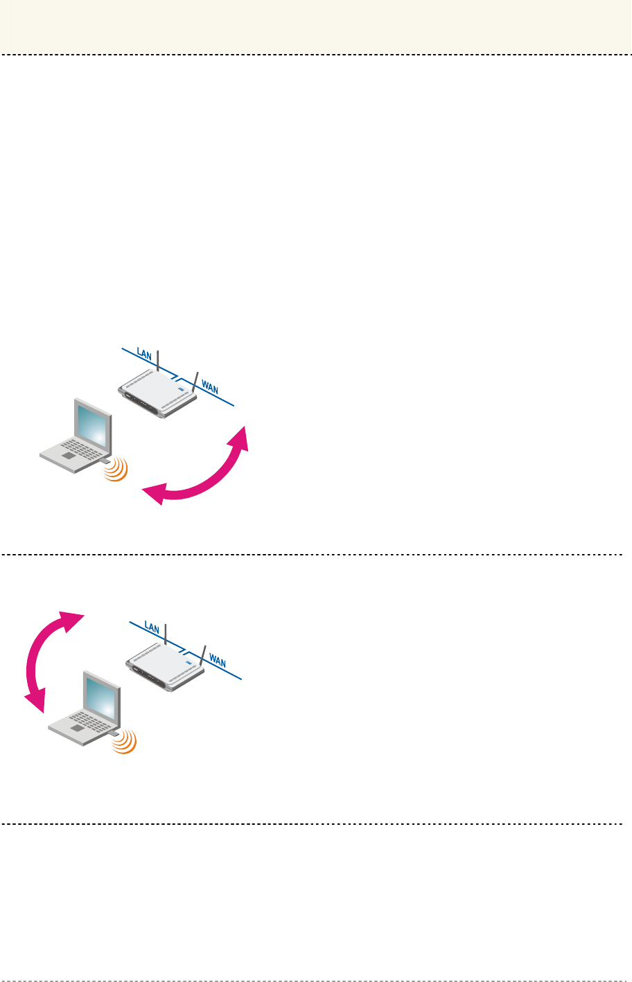
When using UAT operators have to be aware of some principal limitations:
IP: 192.168.2.100
IP: 10.1.1.1/16
IP: 192.168.2.66/24
IP Conflict
Conflict: Subscribers cannot access WAN
services if their IP address overlaps the IP
subnet of the WAN port.
Work-around: Use a public IP address or a
seldom-used private IP address (range) for the
WAN port.
IP: 10.1.1.1
IP: 10.1.1.1/16
IP: 192.168.2.66/24
IP Conflict
Conflict: Subscriber’s IP address must not be
identical to the LAN IP address of the Access
Controller.
Work-around: Use a seldom-used IP address
range for the LAN port.
Chapter 3 – Universal Address Translation
Gemtek Systems Page 22
User’s Guide Chapter 3 – Universal Address Translation
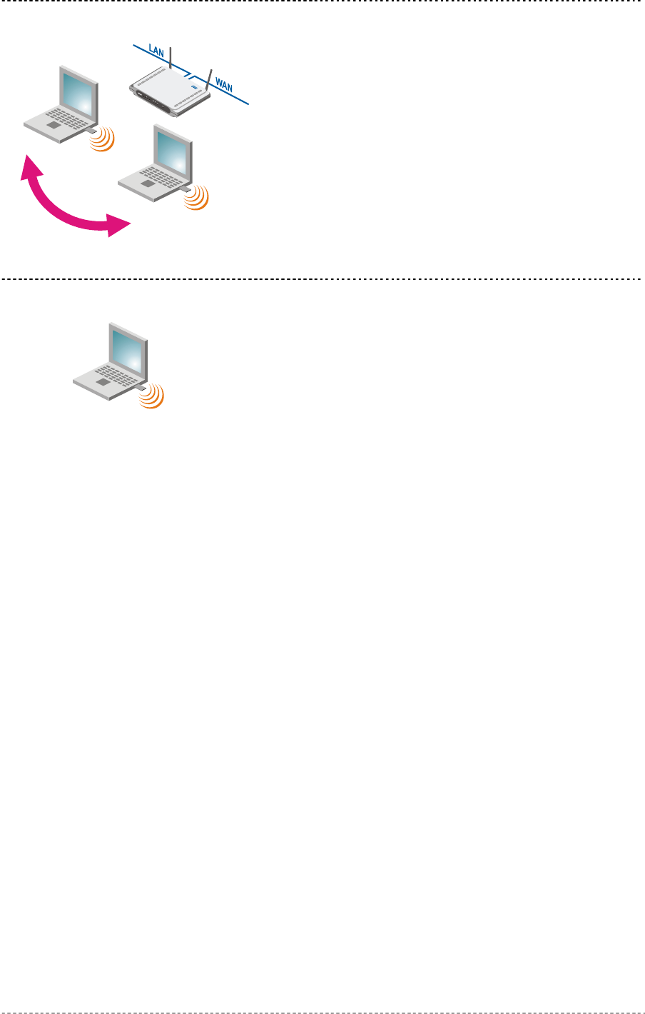
IP: 10.11.11.11
IP: 10.1.1.1/16
IP: 192.168.2.66/24
IP: 10.11.11.11
IP Conflict
Conflict: Two subscribers connected to one
Access Controller cannot use the same IP
address. For instance, this situation can happen
when DHCP and UAT are used in parallel.
Work-around: Enable the DHCP service.
IP: 10.11.11.11
Subnet: 255.255.0.0
Gateway: 10.11.1.254
The subscriber’s IP address and gateway
address must be in the same subnet (a real
network configuration).
Gemtek Systems Page 23

User’s Guide Chapter 4 – User Pages
Chapter 4 – User Pages
This chapter describes what the user pages are and how to manage them. Detailed instructions on
how to change and upload new user pages are given below.
When launching his/her web browser the user's initial HTTP request will be redirected to an operator
defined set of web pages, further called the "user pages". User pages are:
Welcome page– the first page presented to the user.
Login page– subscriber authentication page, allows the user to login to the network.
Logout page– small pop-up window for logged-on user statistics and log-out function.
Help page – get help with the login process.
Unauthorized page – this page is displayed when web login or EAP login methods are disabled
on the Access Controller for subscribers.
One Click page – the additional pop-up pages, displayed when one click roaming for the third
party WLAN operators are preconfigured.
All further presented user pages are factory default. The Hotspot operator can
upload new templates for all user pages.
Gemtek Systems Page 24
User’s Guide Chapter 4 – User Pages
User Pages Overview
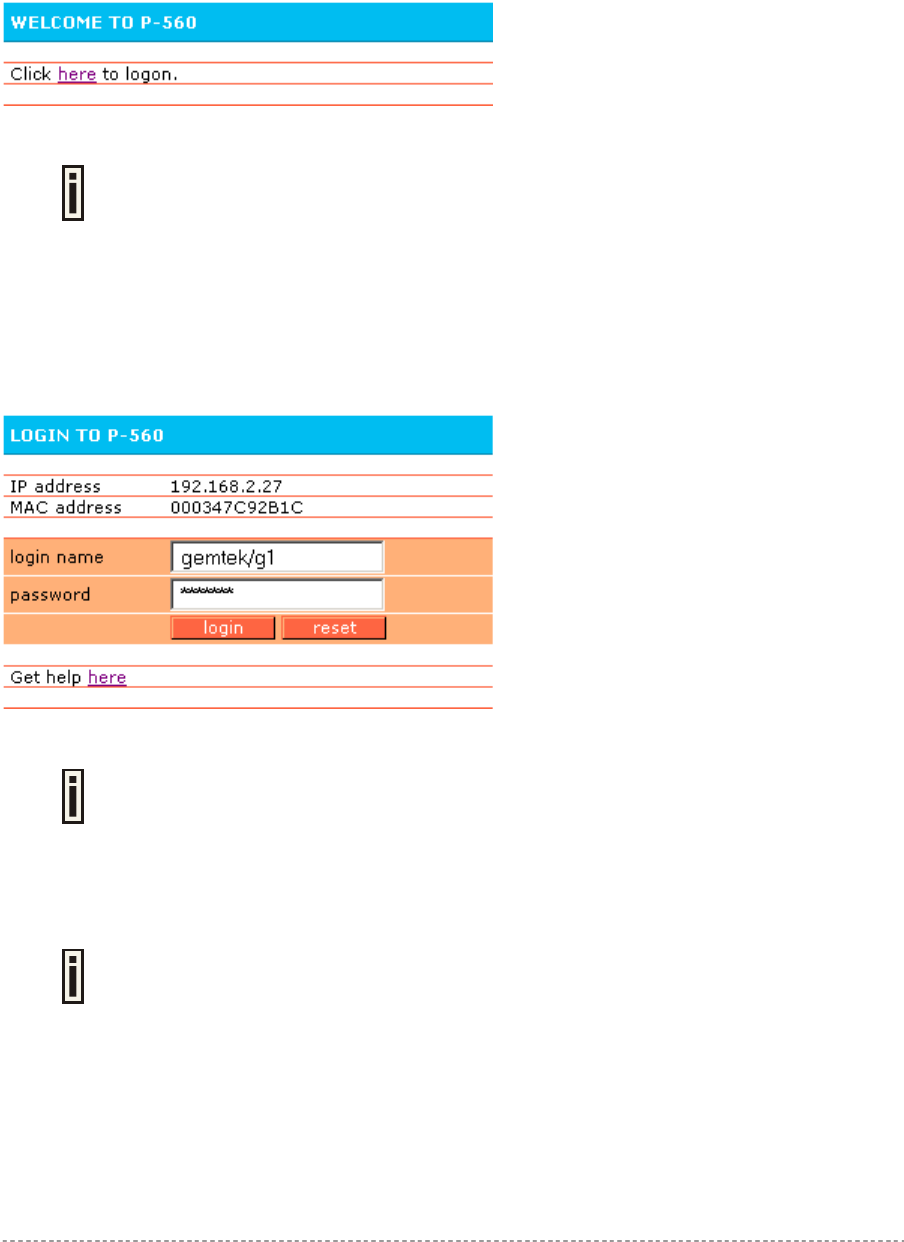
Welcome Page
Welcome page is the first page a Hotspot subscriber receives when he starts his web browser and
enters any URL. By default it’s a very simple page and provides only a link to the login page.
Figure 10 – Welcome Page
The Hotspot operator can change the welcome page according its needs. See
more details in section: Changing User Pages.
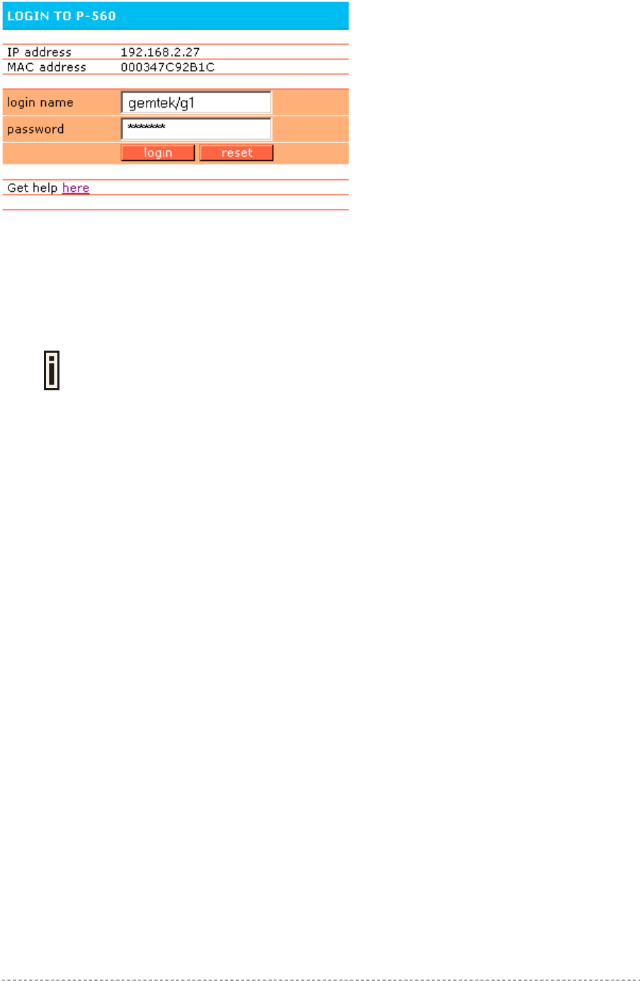
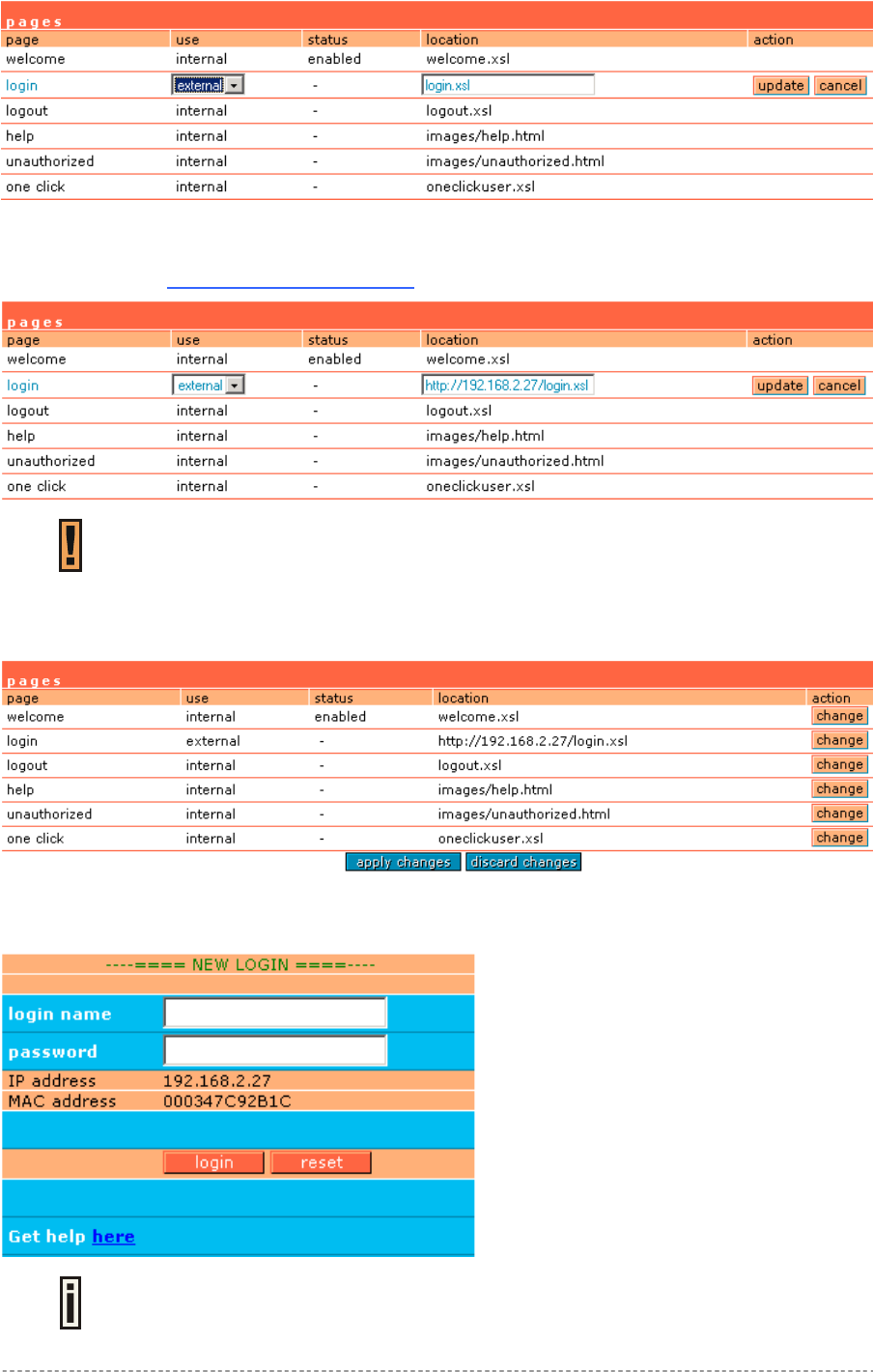
Login Page
The subscriber gets to the login page after clicking the link on the welcome page. The login page is
loaded from the Access Controller. To get access to the network, the user should enter his
authentication settings: login name and password and click the login button:
Figure 11 – Simple Login Page
The login name and password can be obtained from your Hotspot Operator. Login
format available for P-560:
username@WISPdomain
WISPdomain/username
The login page also displays subscriber’s logical and physical network addresses (IP and MAC).
Once authenticated, a start page appears. In addition, a smaller logout window (page) pops up.
The Hotspot operator can change the login page according to its needs. See more
details in section: Changing User Pages.
Gemtek Systems Page 25
User’s Guide Chapter 4 – User Pages
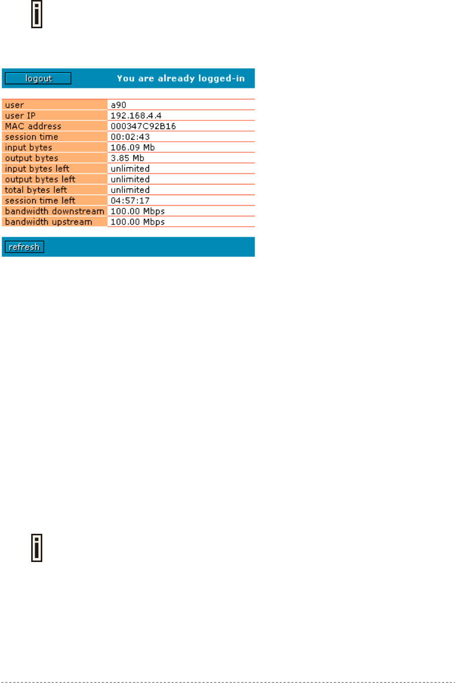
Logout Page
Make sure the JavaScript is enabled on your Web browser; otherwise you will not
receive the logout page.
The Logout page contains the detailed subscriber’s session information and provides function for
logging out of the network:
Figure 12 – Logout Page
Detailed AC subscriber’s session information includes:
User – subscriber’s login name.
User IP – subscriber’s logical network name (IP address).
MAC Address – subscriber’s physical network address.
Session time – subscriber’s session time from client log on in format: [hours: minutes: seconds].
Input/Output bytes – subscriber’s session input and output statistics in bytes.
Input/Output bytes left – session input and output bytes left for subscriber limited from RADIUS [in
B, KB, MB, GB and unlimited].
Total bytes left – session total (input and output) bytes left for subscriber limited form RADIUS [in B,
KB, MB, GB and unlimited].
Session time left – session time left in format: [hours: minutes: seconds].
Bandwidth downstream/upstream – available upstream and downstream bandwidth for subscriber
limited from RADIUS [in bps].
Logout button – click the button to logout from the network. The log-out pop-up window closes.
Refresh button – click the button to refresh the subscriber session information.
The Hotspot operator can change the logout page interface according to its needs.
See more details in section: Changing User Pages. All session details are further
accessible via the operator XML interface.
Gemtek Systems Page 26
User’s Guide Chapter 4 – User Pages
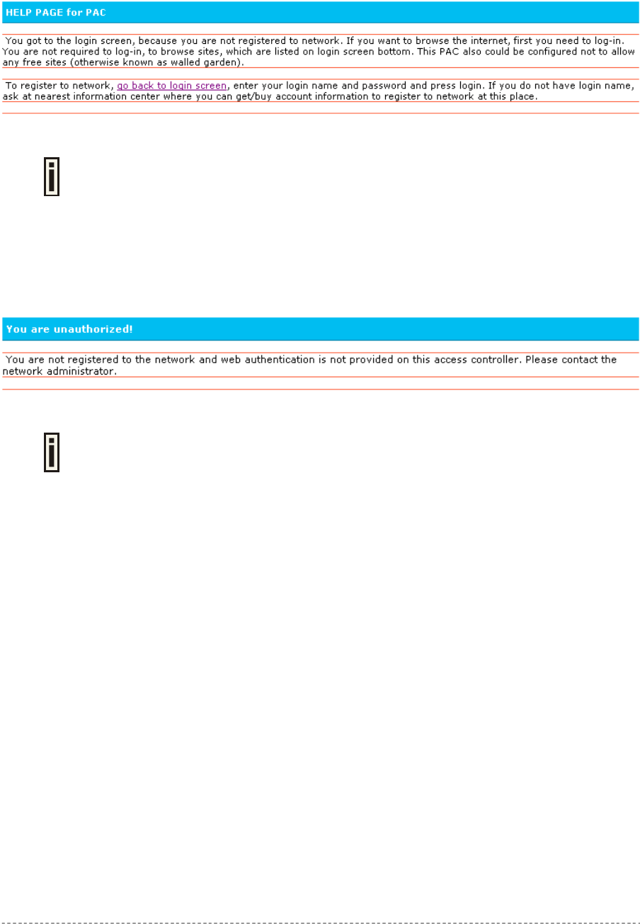
Help Page
Click on the get help link in the login page for help tips related to network registration. A page
appears similar to the following:
Figure 13 – Help Page
The Hotspot operator can change the help page according to its needs. See more
details in section: Changing User Pages.
Unauthorized Page
If web log-on method (UAM) or EAP-based authentication methods are disabled on the AC and the
subscriber attempts to login to the network, he will receive the following page:
Figure 14 – Unauthorized Page
The Hotspot operator can change the unauthorized page according to its needs.
See more details in section: Changing User Pages.
Gemtek Systems Page 27
User’s Guide Chapter 4 – User Pages
Changing User Pages
As the Hotspot operator you can modify the user pages freely according to your personal needs and
preferences. User Page templates can be either stored locally on the AC or on an external web
server.
See the Appendix: G) User Pages Templates Syntax to find the syntax and
comments of all user pages.
Use the user interface | configuration menu to modify user pages. There are two ways to change
and store new user page templates:
External – linking new user page templates from an external server.
Internal – upload new templates to local memory.
Supported user pages template formats:
XSL (Extensible Style sheet Language) for welcome/login/logout/one click pages.
HTML (Hypertext Markup Language for help/unauthorized pages.
The following image formats are supported for new templates. Other formats are not accepted:
PNG
GIF
JPG
The following examples demonstrate the use of internal and external user pages.
User Pages templates samples can be found in the Installation CD delivered to
you with the product.
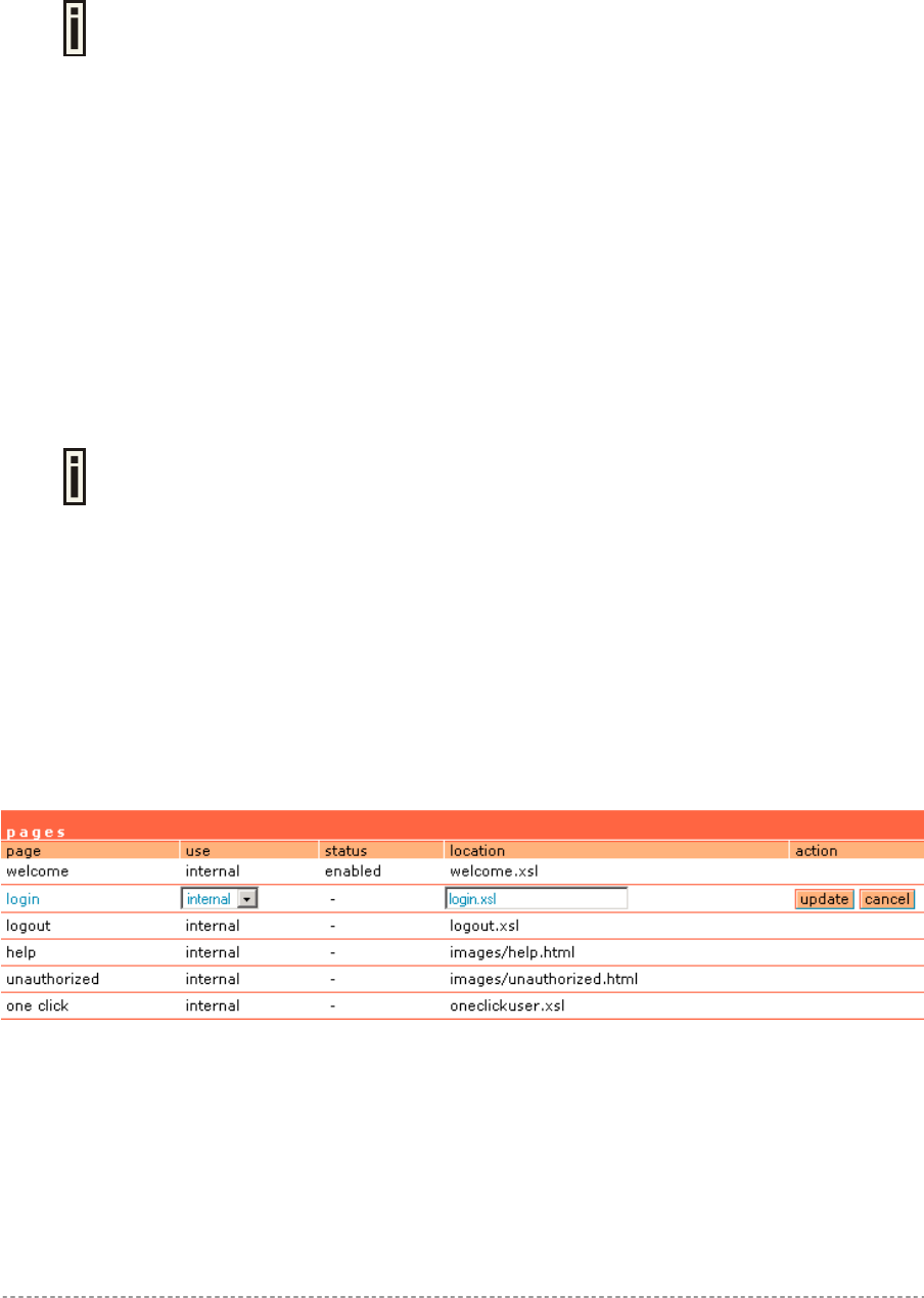
Example for External Pages
Step 1 Prepare your new user pages template for each user page:
welcome/login/logout/help/unauthorized/oneclick.
Step 2 Under the user interface | configuration | pages menu select the user page you
want to change (e.g. login)
Step 3 Choose the external option under the use column:
Gemtek Systems Page 28
User’s Guide Chapter 4 – User Pages
Step 4 Specify the new user page location in the location field
(http://servername/filelocation):
Do not try to upload other than supported formats. Such uploaded pages will not be
displayed properly.
Step 5 Save entered changes with the apply changes button:
Step 6 Check for new uploaded user page (e.g. login):
If at anytime you wish to restore factory default user pages, click the reset button
under the system | reset menu.
Gemtek Systems Page 29
User’s Guide Chapter 4 – User Pages
Example for Internal Pages
We will use the user pages templates from the Installation CD to show the example how to upload
the internal pages. Follow the steps below:
Step 1 Ensure that internal option is selected for all user pages you want to change. By
default internal option is defined for all pages:
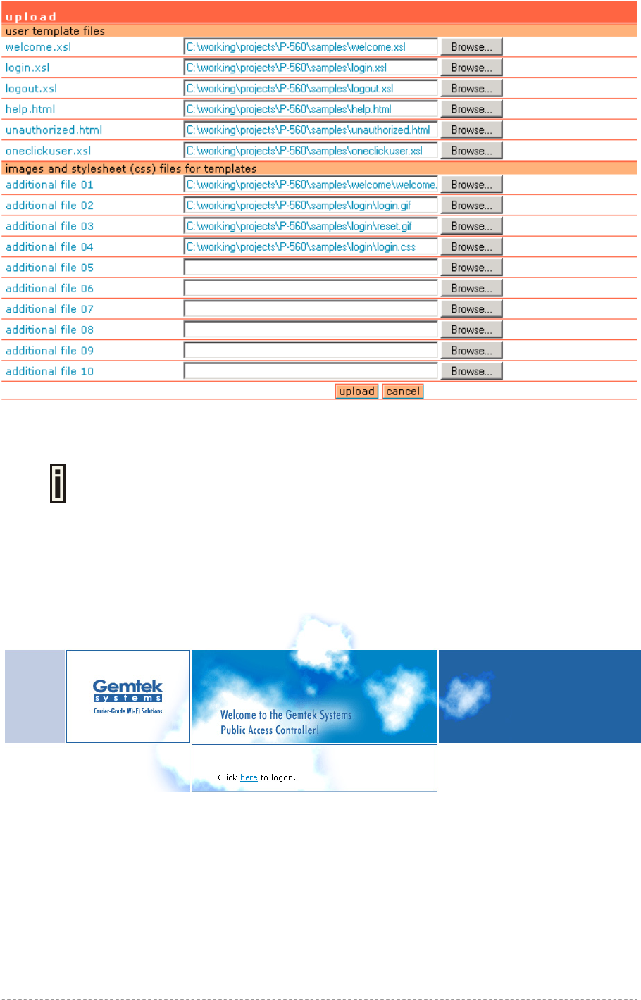
Step 2 Under the user interface | configuration | upload menu click the upload button
to upload new prepared user pages:
The memory space in the AC for internal user pages is limited to 1 MB.
Step 3 Specify the location (Examples directory if you use the Installation CD) of new
user page templates by clicking the browse button or enter the location manually.
Specify the location for the additional files of new user page templates: images and
a cascading style sheet file (css) by clicking the browse button or enter the
location manually:
Gemtek Systems Page 30
User’s Guide Chapter 4 – User Pages
Step 4 Click the upload button to upload specified templates and files.
You do not need to upload all additional files at once. You can repeat the upload
process a number of times until all necessary images are uploaded.
Step 5 Check for the newly uploaded user pages and images to ensure that everything is
uploaded and displayed correctly. Go to the link:
https://<device-IP-address>/ to get to the new user welcome page:
Click the here link or enter the link directly:
https://<device-IP-address>/login.user to get to the new user login
page:
Gemtek Systems Page 31

User’s Guide Chapter 4 – User Pages
If at anytime you wish to restore the factory default user pages, click the reset
button under the system | reset menu.
Gemtek Systems Page 32
User’s Guide Chapter 4 – User Pages
Extended UAM
The Extensions feature (user interface | configuration menu) allows an external Web Application
Server (WAS) to intercept/take part in the user authentication process externally log on and log off the
user as necessary. It provides means to query user session information as well.
See the following schemes to understand how the remote client authentication works.
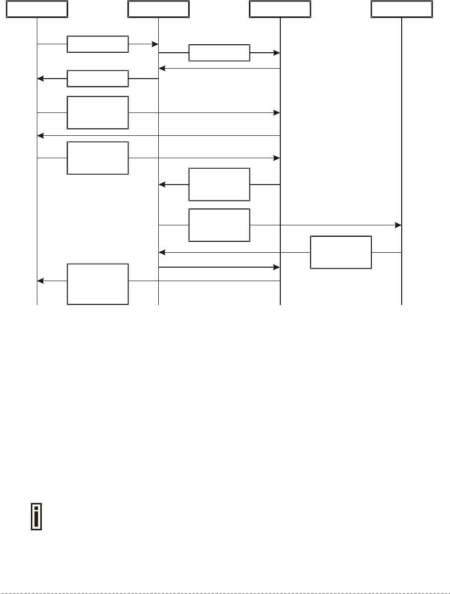
Scheme 1:
Client AC WAS RADIUS Server
1. Initial Request
3. Renders HTML
4. Direct client
communication
with WAS
5. Client sends
his/her login and
password
9. WAS reports
client status:
authenticated or
not
2. Fetch XSL
6. WAS tries to
authenticate
client
7. AC sends
request to
RADIUS
8. RADIUS reply
authenticated or
not
Figure 15 – Client Remote Authentication Scheme (1)
Client initiates (1) authentication process. AC intercepts any access to the Internet via HTTP and
redirects the client to the welcome, or login URL on AC. In order to render the custom login screen
HTML page, the AC must be configured to (2) fetch .XSL script from a remote server, which in this
case is a Web Application Server (WAS), or have custom .XSL uploaded on the AC. There is the
ability to enable caching of .XSL scripts (see: User Interface | Configuration | Pages), thus avoiding
fetching of the same document every time a client requests authentication.
The AC (3) uses .XSL script to render HTML output, which is done by feeding a XML document to a
parsed and prepared for rendering .XSL script. The latter XML document contains all needed
information for Web Application Server like user name, password (if there was entered), user IP
address, MAC address and NAS-Id. Custom .XSL script must generate initial welcome/login screen
so that it embeds all the needed information in a HTML FORM element as hidden elements and
POST data not back to the AC, but to the Web Application Server (5). Thereafter the client
communicates directly with the Web Application Server.
Find more details on how to prepare the .XSL templates to renter the HTML in
Appendix: G) User Pages Templates Syntax.
Gemtek Systems Page 33
User’s Guide Chapter 4 – User Pages
When the Web Application server has all needed data from the client, it must try to authenticate (6)
the client. Authentication is done by the RADIUS server but through the AC. At this step the shared
secret is used to make the connection between the WAS and the AC. The AC re-sends the
authentication request to the RADIUS server (7). Depending on the status, appropriate authentication
status must be returned back to the WAS but through the AC (8). In step (9), the Web Application
Server knows the client authentication status and reports success or failure back to the client.
The Web Application Server (WAS) must be configured as a free site in the Walled
Garden area.
There is an ability to skip the rendering initial user pages from the .XSL. See the following scheme
when the user initial request is redirected to the specified location.
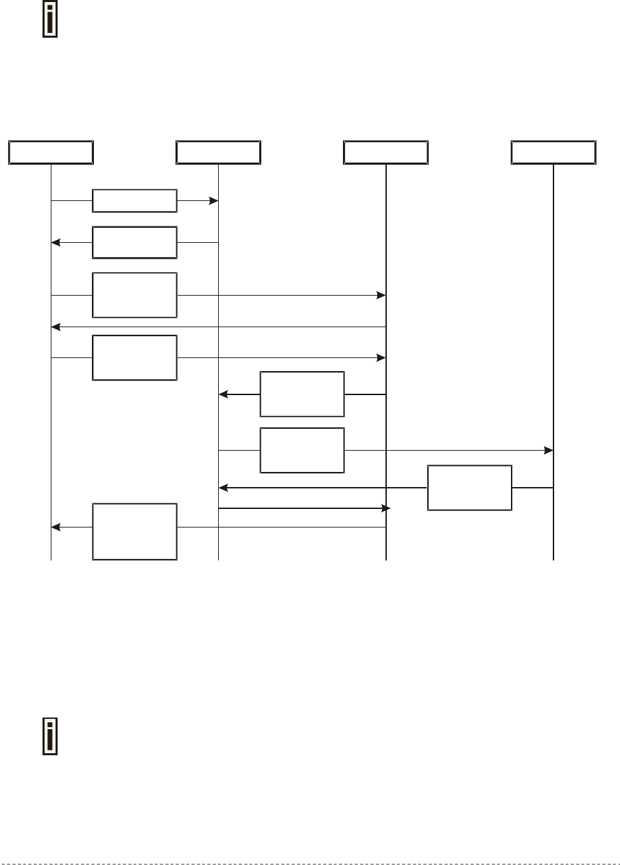
Scheme 2:
Client AC WAS RADIUS Server
1. Initial Request
2. Replay with
HTTP redirect
3. Direct client
communication
with WAS
4. Client sends
his/her login and
password
8. WAS reports
client status:
authenticated or
not
5. WAS tries to
authenticate
client
6. AC sends
request to
RADIUS
7. RADIUS replay
authenticated or
not
Figure 16 – Client Remote Authentication Scheme (2)
The initial client request (1) can be redirected to the specified location, as redirection URL on the
Web Application server. In such case the client who wants to authenticate gets the redirection from
AC (2). In other words the AC intercepts any access to the Internet via HTTP and redirects the client
to the defined welcome, or login URL on WAS (also see: User Interface | Configuration | Pages).
The further actions are the same as described in the Scheme 1 (Figure 15 – Client Remote
Authentication Scheme (1)).
The WAS location URL under welcome page redirect must be configured as a free
site in the Walled Garden area.
To define such redirection URL use the user interface | configuration | pages menu. Enable
welcome page, set the redirect setting and specify the redirect location for such authentication
process (also see: User Interface | Configuration | Pages).
Gemtek Systems Page 34

User’s Guide Chapter 4 – User Pages
Parameters Sent to WAS
Parameters that are sent to the WAS for user authentication pages redirection:
parameter description
nasid NAS server ID value. Can be changed or specified under the network
interface | RADIUS | RADIUS settings menu
nasip P-560 WAN IP address. Can be changed or specified under the network
interface | configuration | interface configuration menu.
cientip Client IP address. Cannot be defined manually.
mac Client MAC address. Cannot be defined manually.
ourl Initial URL where not authorized client enter to his/her browser and tries to
browse. After authentication the user is redirected in this URL (optional).
sslport HTTPS port number of AC (by default: 443). Not configurable.
lang Parameter "accept-language" from client browser request (optional).
In order to logon, log-off or get user status WAS submits POST request to the following URLs:
1. Remote user logon
Script name: pplogon.user
Parameters (all parameters are required):
secret shared secret, to protect page from accidental use
ip IP address of user to be logged on.
username Username of the user to be logged on.
password Password of the user to be logged on.
Script call example:
https://P560/pplogon.user?secret=sharedSecret&ip=<user_IP_address>&username
=userName&password=UserPassword
Script produces XML output:
<logon>
<status>Ok</status>
<error>0</error>
<description>User logged on.</description>
<replymessage>Hello user!</replymessage>
</logon>
Response status and error codes:
status error description
OK 0 User is logged on.
Not checked 100 Logon information not checked.
No IP 101 No user IP address supplied.
No username 102 No username supplied.
Disabled 103 Remote authentication is disabled.
Bad secret 104 Incorrect shared secret supplied.
No password 105 No user password.
OK 110 User already logged on.
Failed to authorize 111 Failed to authorize user.
Bad password 112 Incorrect username or/and password.
Gemtek Systems Page 35

User’s Guide Chapter 4 – User Pages
Network failed 113 Network connection failed.
Accounting error 114 Accounting error.
Too many users 115 Too many users connected.
Unknown authorization error 120 Unknown authorization error.
<replymessage> is RADIUS Reply-Message attribute value. If RADIUS responds with Reply-
Message(s), they are added to logon response. If RADIUS does not responds with Reply-Message,
<replymessage> attribute is not added to output XML.
See the Appendix: E) Standard RADIUS Attributes for all supported RADIUS
attributes.
2. Remote user log-off
Script name: pplogoff.user
Parameters:
secret shared secret, to protect page from accidental use
ip IP address of user to be logged off.
username Username of the user to be logged off.
mac AC address of the user to be logged off.
All parameters are required, except the IP and MAC. At least one of IP and MAC addresses should be
supplied. If supplied only IP, user is checked and logged off by username and IP. If IP and MAC
addresses are supplied, then user is checked and logged off by username, IP and MAC addresses.
Script call example:
https://P560/pplogoff.user?secret=sharedSecret&username=UserName&ip=<user_I
P_address>
Script produces XML output:
<logoff>
<status>Ok</status>
<error>0</error>
<description>User logged off.</description>
</logoff>
Response statuses and error codes:
status error Description
OK 0 User is logged off.
Not checked 100 Logoff information not checked.
No username 102 No username supplied.
Disabled 103 Remote authentication is disabled.
Bad secret 104 Incorrect shared secret supplied.
No IP/MAC 106 No user IP and/or MAC address
supplied.
No user by MAC 121 User with supplied MAC address not
found.
No user by IP 122 User with supplied IP address and
username not found.
No user by IP and MAC 123 User with supplied IP, MAC
addresses and username not found.
Gemtek Systems Page 36

User’s Guide Chapter 4 – User Pages
Failed to logoff 131 Failed to logoff user.
Cannot resolve IP 132 Cannot resolve user IP.
Unknown logoff error 140 Unknown logoff error.
3. Remote user status
Script name: ppstatus.user
Parameters:
secret shared secret, to protect page from accidental use
ip IP address of user to get status.
username Username of the user to get status.
All parameters are required.
Script call example:
https://P560/ppstatus.user?secret=sharedSecret&username=UserName&ip=<user_I
P_address>
Script produces XML output:
XML output, when some error occurs:
<ppstatus>
<status>No user by IP</status>
<error>122</error>
<description>User with supplied IP address not found.</description>
</ppstatus>
Response statuses and error codes:
status error description
OK 0 User status is ok.
Not checked 100 Status information not checked.
No IP 101 No user IP address supplied.
No username 102 No username supplied.
Disabled 103 Remote authentication is disabled.
Bad secret 104 Incorrect shared secret supplied
No user by IP 122 User with supplied IP address not
found.
No user by IP and username 141 User with supplied IP address and
username not found.
XML output when no errors and user statistics got successfully:
<ppstatus>
<status>Ok</status>
<error>0</error>
<description>Got user status.</description>
<entry id="1">g17</entry>
<entry id="2">192.168.2.117</entry>
<entry id="3">200347C92B63</entry>
<entry id="4">00:00:05</entry>
Gemtek Systems Page 37

User’s Guide Chapter 4 – User Pages
<entry id="5">3E64C7967A36</entry>
<entry id="6">00:01:10</entry>
<entry id="7">0 bytes</entry>
<entry id="8">0 bytes</entry>
<entry id="9">testlab</entry>
<entry id="10">unlimited</entry>
<entry id="11">unlimited</entry>
<entry id="12">unlimited</entry>
<entry id="13">32 Mbps</entry>
<entry id="14">32 Mbps</entry>
<entry id="15">04:59:55</entry>
<entry id="16">EAP</entry>
</ppstatus>
Status detailed information by ID:
id description
1 User name
2 User IP address
3 User MAC address
4 Session time
5 Session ID
6 User idle time
7 Output bytes
8 Input bytes
9 User WISP name
10 Remaining bytes
11 Remaining output bytes
12 Remaining input bytes
13 Bandwidth upstream
14 Bandwidth downstream
15 Remaining session time
16 Authentication method
Gemtek Systems Page 38

User’s Guide Chapter 5 – Command Line Interface
Chapter 5 – Command Line Interface
Introduction
The CLI (Command Line Interface) software is a configuration shell for the Access Controller. Using
the CLI system operator can configure:
User interface
Network interface
Wireless interface
System
Using the CLI system operator can check:
Status (device, network, service)
Connection
All available key combinations in CLI mode are listed in the table below:
Key and/or Combination Function
? Get context-sensitive help
<TAB> Complete the current keyword or list all the options
<CTRL> <D> Break out the sub-shell
<CTRL> <A> Jump to the beginning of the line
<CTRL> <E> Jump to the end of the line
<CursUP>/<CursDOWN> Scroll through the history of commands
Figure 17 – Key Combinations in the CLI
Get Connection to CLI
There are three different ways to get a connection to the CLI of the Access Controller, via the:
Telnet
SSH client
Telnet Connection
Make sure that default access status is allowed and telnet function is enabled on
the AC before trying to connect via telnet. Otherwise, no telnet connection will be
available.
Connect the Access Controller via LAN or WAN ports using the enclosed UTP cable and start a telnet
session (using a telnet application). For example, connect your device via the WAN port, and then
make a telnet connection as the following:
telnet 192.168.2.66
where 192.168.2.66 is the default WAN interface IP. Login to CLI mode and the prompt will be
displayed automatically. Enter the administrator login settings (refer to the Login section for details).
Gemtek Systems Page 39
User’s Guide Chapter 5 – Command Line Interface
SSH Connection
Make sure that default access status is enabled on the AC before attempting to
connect via SSH. Otherwise no SSH connection will be available.
Connect the Access Controller via LAN or WAN ports using the enclosed UTP cable and start a SSH
session (using an application as PuTTY). For example connect your device via the WAN port and
then make a SSH connection to host IP: 192.168.2.66 (default WAN interface IP).
Login to CLI mode prompt will be displayed automatically. Enter the administrator login settings (refer
to the next section for details).
Login
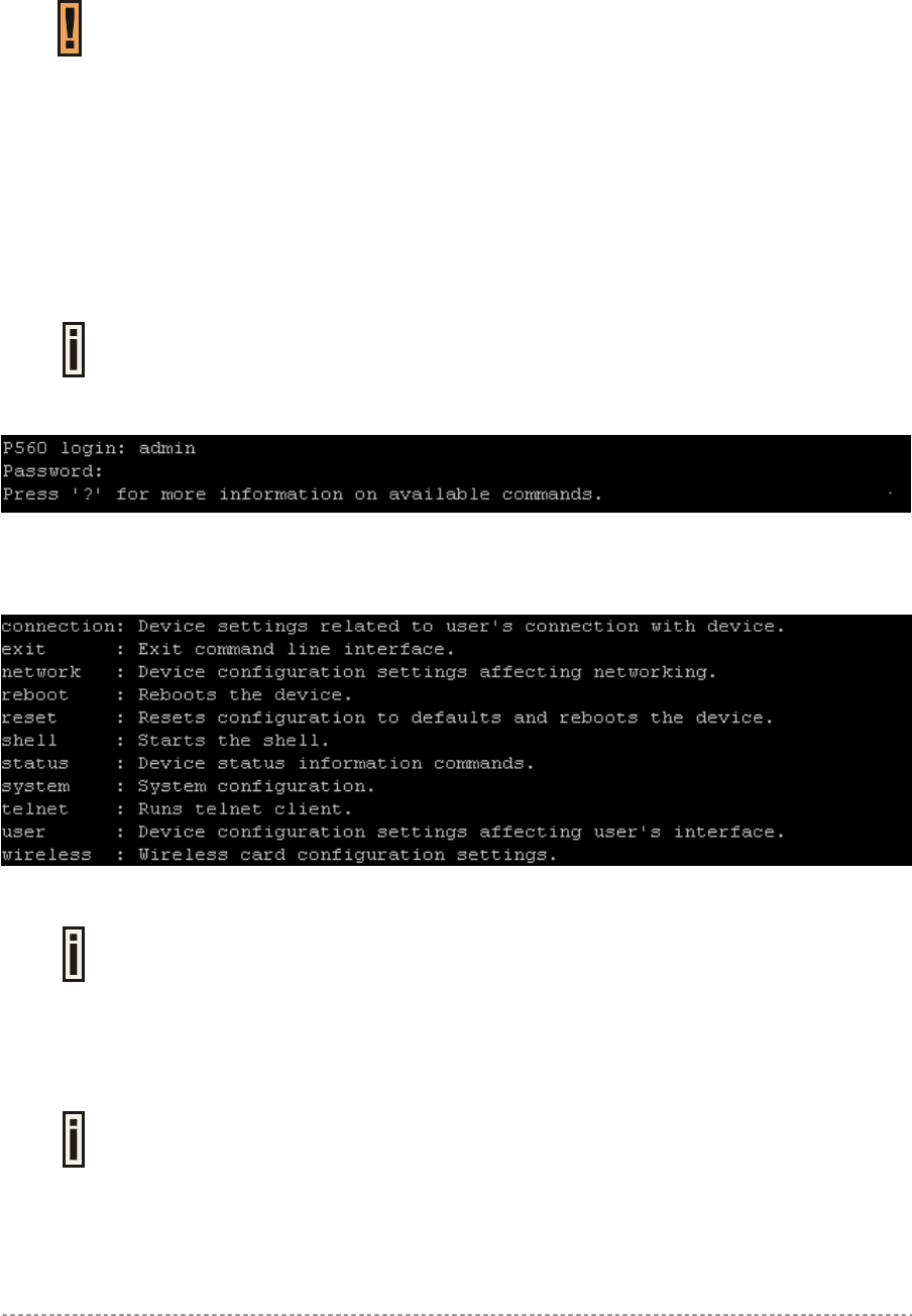
Enter the administrator login settings in the displayed CLI command prompt.
The default administrator login settings:
Login: admin
Password: admin01
Figure 18 – CLI Login
After a successful login command prompt is displayed, the CLI is ready for commands. Press ‘?’ to
get a list of main commands:
Figure 19 – Main CLI Commands
‘?’ will not appear on the screen. While pressing this character, the display changes
to the desired help page. To enter ‘?’ as character type ‘\?’.
Connection
Connection is a category of command that is related to the user’s connection with the device.
A full list of all available connection commands/subcommands and its parameters
is available in the Appendix section: D) CLI Commands and Parameters.
In general, connection usage is as follows:
connection <command> <value>
To get a list of all available commands in the connection category type:
Gemtek Systems Page 40
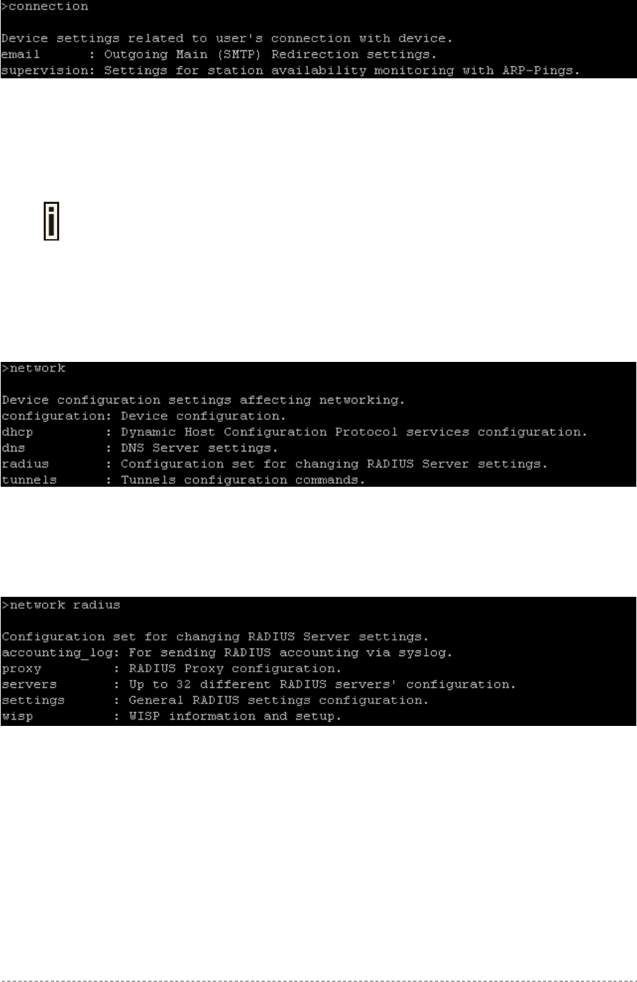
User’s Guide Chapter 5 – Command Line Interface
connection ?
Figure 20 – Connection Commands
Network
Network is a category of commands that configures controller interface settings, DNS, DHCP, UAT
and RADIUS settings.
A full list of all available network commands/subcommands and its parameters is
available in the Appendix section D) CLI Commands and Parameters.
The network commands themselves contain several subcommands and the subcommands again
contain several parameters. In general, network command usage is as follows:
network <command> <subcommand1> <subcommand2> [-parameter] <value>
To get a list of all available commands in the configure category, type:
network ?
Figure 21 – Network Commands List
To get a list of all-available subcommands for a specific command, type:
network <command> ?, (e.g. network radius ?)
All available subcommands for radius are displayed:
Figure 22 – Configure Network (1)
Specific command contains several subcommands:
network <command> <subcommand1> ?, (e.g. network radius servers ?)
All available subcommands are displayed:
Gemtek Systems Page 41
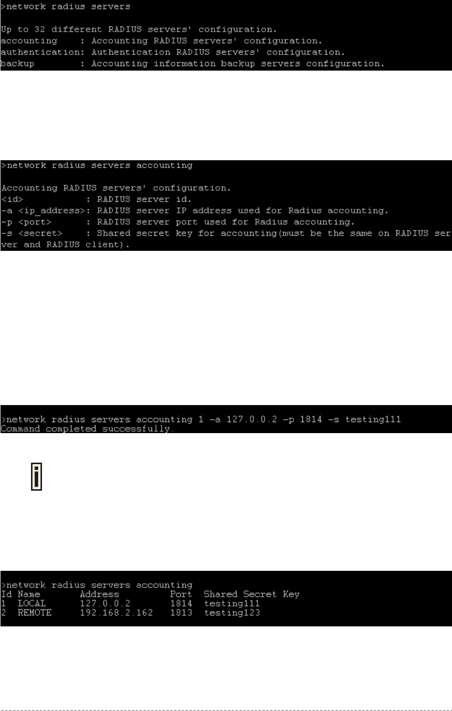
User’s Guide Chapter 5 – Command Line Interface
Figure 23 – Configure Network (2)
To get a list for available parameters on selected subcommand, type:
network <command> <subcommand1> <subcommand2> ?, (e.g. network radius
servers accounting ?)
All available parameters on entered subcommand are displayed:
Figure 24 – Configure Network (3)
To configure the desired controller interface setting, type all required parameters with values and
subcommands:
network <command> <subcommand1> <subcommand2> [-parameter] <value>
(e.g. network radius servers accounting 1 –a 127.0.0.2 –p 1814 –s
testing111), where parameters are as follows:
-a – RADIUS server IP address used for RADIUS accounting
-p – RADIUS server port number used for RADIUS accounting
-s – Shared secret key for accounting.
Figure 25 – Configure Network (4)
If successful, a message regarding the successful completion is displayed;
otherwise, an error message is displayed.
In some cases, entered commands without parameters display current controller configuration or
settings:
network <command> <subcommad1> <subcommad2>, (e.g. radius servers
accounting), displays available RADIUS servers and its settings list (in this case, the RADIUS
accounting server which is already updated):
Figure 26 – Configure Network (5)
Gemtek Systems Page 42
User’s Guide Chapter 5 – Command Line Interface
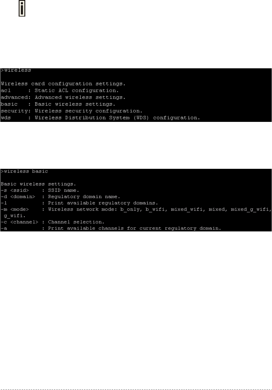
Wireless
Wireless is a category of commands that configures controller basic and advanced wireless interface
settings, access control list (ACL) and WDS.
A full list of all available wireless commands/subcommands and its parameters is
available in the Appendix section: D) CLI Commands and Parameters.
The wireless commands themselves contain several subcommands and the subcommands again
contain several parameters. In general, wireless command usage is as follows:
wireless <command> <subcommand1> [-parameter] <value>
To get a list of all available commands in the configure category, type:
wireless ?
Figure 27 –Wireless Commands List
To get a list of all-available subcommands for a specific command, type:
wireless <command> ?, (e.g. wireless basic ?)
All available subcommands for radius are displayed:
Figure 28 – Configure Wireless Basic
To configure the desired controller interface setting, type all required parameters with values and
subcommands. Use the samples from previous section.
Gemtek Systems Page 43
User’s Guide Chapter 5 – Command Line Interface
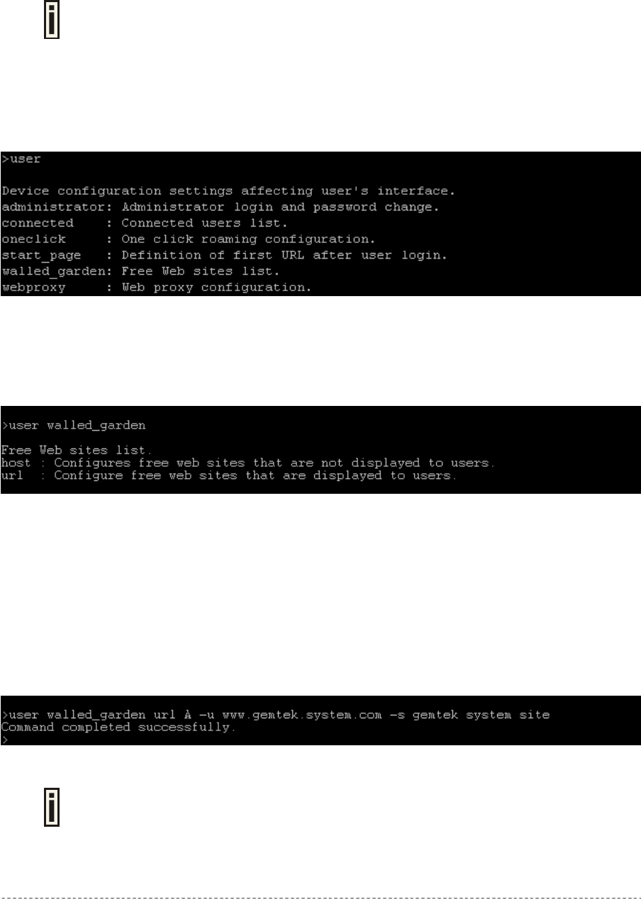
User
User is a category of commands that configures controller interface settings, affecting the user’s
interface: redirection URL, free sites (walled garden), system management access, administrator
login/password.
A full list of all available user commands/subcommands and their parameters is
available in the Appendix section: D) CLI Commands and Parameters.
In general, the user command usage is as follows:
user <command> <subcommand1> <subcommand2> [-parameter] <value>
To get the full list of the user commands, type:
user ?
Figure 29 – User Commands List
To get a list of all-available subcommands for a specific command, type:
user <command> ?, (e.g. user walled_garden ?)
All available subcommands for walled garden (free sites) are displayed:
Figure 30 – Configure User Interface (1)
To configure selected user interface settings, type:
User <command> <subcommand1> <subcommand2> [-parameter] <value>,
(e.g. user walled_garden url A -u www.gemtek.system.com -s gemtek system
site), where parameters are as follows:
A – action: add URL
-u – define URL address
-s – define URL description, visible for user:
Figure 31 – Configure User Interface (2)
If successful, a message regarding the successful completion is displayed;
otherwise, an error message is displayed.
Gemtek Systems Page 44
User’s Guide Chapter 5 – Command Line Interface
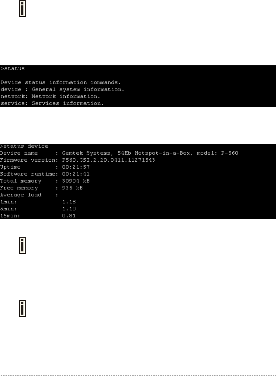
Status
Status is a category of commands that’s displays:
General devices status (model, firmware version, uptime, memory)
All interface network settings (IP address/netmask, MAC address, gateway, RX/TX statistics)
Currently running services (DHCP, routes, port forward, telnet, SNMP, UAT, ..).
A full list of all available status commands/subcommands and their parameters is
available in the Appendix section: D) CLI Commands and Parameters.
In general the status command usage is as follows:
Status <command>
To get the full list of the status commands, type:
status ?
Figure 32 – System Status Commands List
To get the general device status information, type:
status device :
Figure 33 – Device Status
Here you can find the current firmware version of your AC. This is important
information for support requests and for preparing firmware uploads.
System
System is a category of commands that configures access to controller (telnet, AAA methods, L2
isolation, SNMP, UAT) and configuration: clock, NTP, syslog, trace.
A list of all available system commands/subcommands and their parameters are
available in the Appendix section: D) CLI Commands and Parameters.
In general, the system command usage is as follows:
system <command> <subcommand1> <subcommand2> [-parameter] <value>
To get the full list of the system commands, type:
system ?
Gemtek Systems Page 45
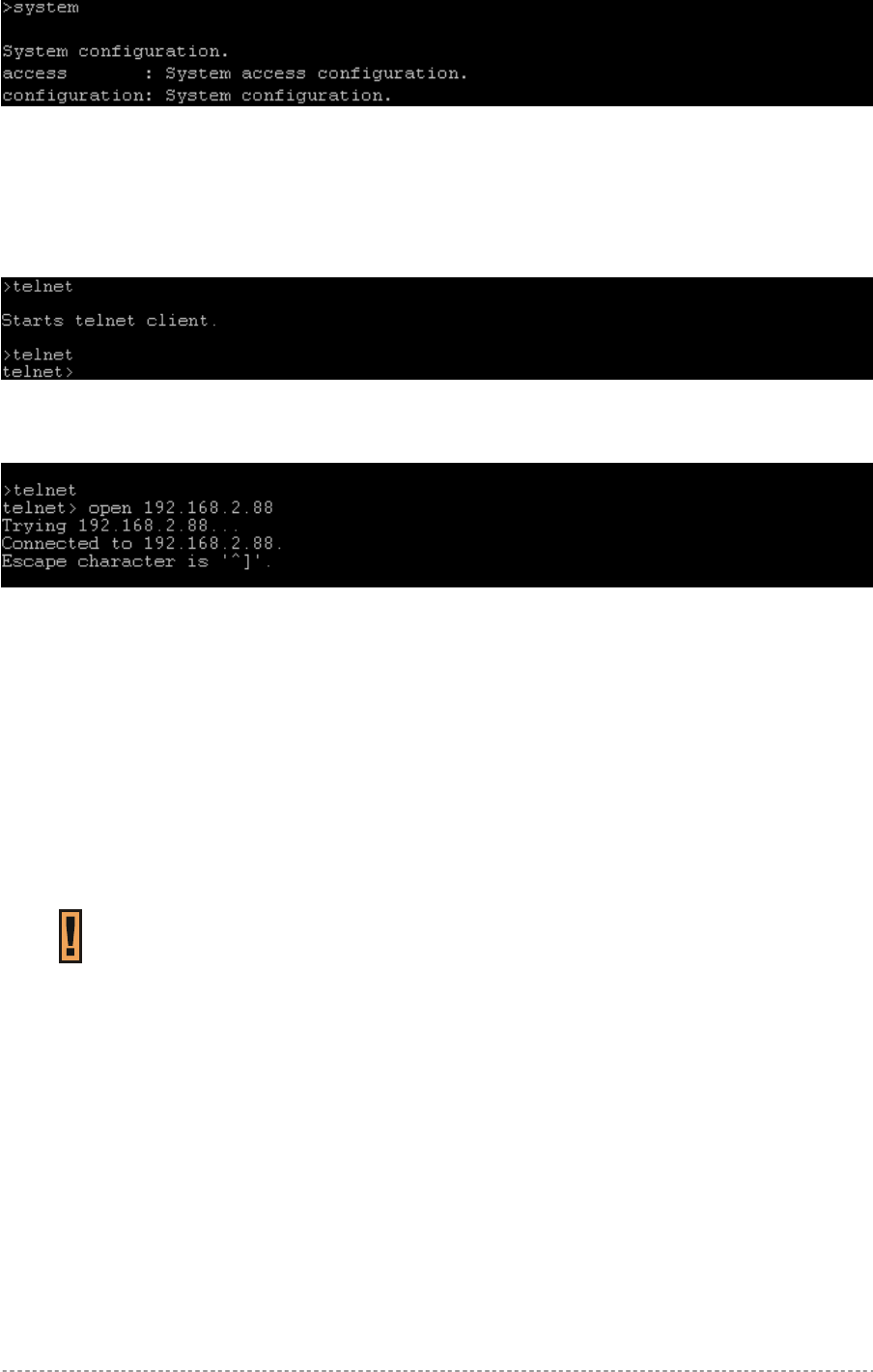
User’s Guide Chapter 5 – Command Line Interface
Figure 34 – System Commands List
Telnet
To make a telnet connection, type the telnet command in the command line:
telnet
Figure 35 – Telnet Command
The telnet client is activated and ready for a telnet session.
Figure 36 – Telnet Session
Quit the telnet to return to CLI interface.
Reboot
To stop the controller and reboot the device, type the reboot command in the command line. No
configuration changes are done. The last saved configuration is applied to the rebooted controller.
Reset
To reset the controller to factory defaults, type the reset command. The device is restarted and
defaults values are set.
Please note, that even the administrator password will be set back to the factory
default. Refer to Appendix section: B) Factory Defaults for the Access
Controller.
Exit
To leave the CLI mode, type the Exit command in the command line.
Gemtek Systems Page 46

User’s Guide Chapter 6 – SNMP Management
Chapter 6 – SNMP Management
Introduction
Another way to configure and monitor the Access Controller (P-560) via a TCP/IP network is SNMP
(Simple Network Management Protocol).
SNMP is an application layer protocol that facilitates the exchange of management information
between network devices. It is part of the Transmission Control Protocol/Internet Protocol (TCP/IP)
protocol suite. SNMP enables network administrators to manage network performance, find and solve
network problems, and plan for network growth.
The SNMP agent and management information base (MIB) reside on the Access Controller. To
configure SNMP on the controller, you define the relationship between the Network Management
System (NMS) and the SNMP agent (our AC). The SNMP agent contains MIB and Gemtek Systems
private MIB variables whose values the SNMP manager can request or change. A NMS can get a
value from an agent or store a value into the agent. The agent gathers data from the MIB, the
repository for information about device parameters and network data. The agent can also respond to
a manager’s requests to get or set data.
In order to manage the device you have to provide your Network Management
System software with adequate MIB files. Please consult your management
software manuals on how to do that.
SNMP Versions
Access Controller supports the following versions of SNMP:
SNMPv1—The Simple Network Management Protocol: A Full Internet Standard, defined in RFC
1157. (RFC 1157 replaces the earlier versions that were published as RFC 1067 and RFC 1098.)
Security is based on community strings.
SNMPv2c—The community-string based Administrative Framework for SNMPv2. SNMPv2c (the
"C" stands for "community") is an Experimental Internet Protocol defined in RFC 1901, RFC 1905,
and RFC 1906. SNMPv2c is an update of the protocol operations and data types of SNMPv2p
(SNMPv2 Classic), and uses the community-based security model of SNMPv1.
SNMPv3 – SNMP v3 is based on version 2 with added security features. It addresses security
requirements through encryption, authentication, and access control rules.
Both SNMPv1 and SNMPv2c use a community-based form of security. The community of managers
able to access the agent's MIB is defined by an IP address access control list and password.
The Access Controller implementation of SNMP supports all MIB II variables (as described in RFC
1213) and defines all traps using the guidelines described in RFC 1215.The traps described in this
RFC are:
coldStart
A coldStart trap signifies that the SNMP entity, acting in an agent role, is reinitializing itself
and that its configuration may have been altered.
WarmStart
A WarmStart trap signifies that the SNMP entity, acting in an agent role, is reinitializing itself
Gemtek Systems Page 47

User’s Guide Chapter 6 – SNMP Management
and that its configuration is unaltered.
authenticationFailure
An authenticationFailure trap signifies that the SNMP entity, acting in an agent role, has
received a protocol message that is not properly authenticated.
linkDown
A linkDown trap signifies that the SNMP entity, acting in an agent role, recognizes a failure in
one of the communication links represented in the agent's configuration.
linkUp
A linkUp trap signifies that the SNMP entity, acting in an agent role, recognizes that one of
the communication links represented in the agent's configuration has come up.
SNMP Agent
The SNMP agent responds to SNMP manager requests as follows:
Get a MIB variable—The SNMP agent begins this function in response to a request from the
SNMP manager. The agent retrieves the value of the requested MIB variable and responds to the
manager with that value.
Set a MIB variable—The SNMP agent begins this function in response to a message from the
SNMP manager. The SNMP agent changes the value of the MIB variable to the value requested
by the manager.
The SNMP agent also sends unsolicited trap messages to notify an SNMP manager that a significant
event has occurred (e.g. authentication failures) on the agent.
SNMP Community Strings
SNMP community strings authenticate access to MIB objects and function as embedded passwords.
In order for the SNMP manager to access the controller, the community string must match one of the
two community string definitions on the controller. A community string can be as follows:
Read-only—Gives read access to authorized management stations to all objects in the MIB
except the community strings, but does not allow write access.
Read-write—Gives read and write access to authorized management stations to all objects in the
MIB, but does not allow access to the community strings.
Gemtek Systems Page 48

User’s Guide Chapter 6 – SNMP Management
Use SNMP to Access MIB
As shown in the picture Figure 37 – SNMP Network SNMP agent gathers data from the MIB. The
agent can send traps (notification of certain events) to the SNMP manager, which receives and
processes the traps. Traps are messages alerting the SNMP manager to a condition on the network
such as improper user authentication, restarts, link status (up or down), MAC address tracking, and so
forth. The SNMP agent also responds to MIB-related queries sent by the SNMP manager in get-
request, get-next-request, and set-request format.
MIB
SNMP Agent
P-560
SNMP Manager
get-response, traps
get-request, get-next-reguest, get-bulk, set-request
Figure 37 – SNMP Network
Gemtek Private MIB
In addition to standard SNMP MIBs, Gemtek P560 supports private Gemtek MIB. The private MIBs
are enterprise specific and serve to extend the functionality of the standard MIBs. Private MIB
identifies manageable objects and their properties that are specific to the managed device. MIBs let
you manage device not only by using WEB or Command Line Interface but also using SNMP protocol.
The descriptions and brief explanations of managed objects are available in the MIB file. The MIB file
is a specially formatted text file. It is using the so-called ASN.1 standard syntax.
Gemtek Systems Page 49
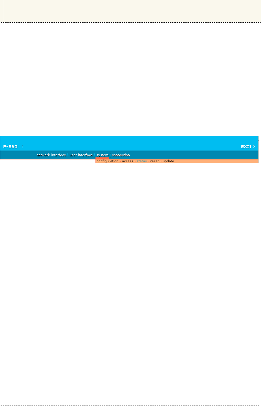
User’s Guide Chapter 7 – Reference Manual
Chapter 7 – Reference Manual
This chapter contains Hotspot-in-a-Box web management reference information.
The web management main menu consists of the following sub menus:
Network Interface – device configuration settings affecting networking.
User Interface – device configuration settings affecting the user interface.
System – device system configuration settings directly applicable to the controller.
Connection– device settings related to user’s connection with the P560.
Exit – click exit and leave the web management then close your web-browser window.
Web Interface
The main web management menu is displayed at the top of the page after successfully logging into
the system (see the figure below). From this menu all essential configuration pages are accessed.
Figure 38 – Main Configuration Management Menu
By default the system | status menu is activated and the current AC system status is displayed. The
active menu is displayed in a different color.
The web management menu has the following structure:
Network Interface
Configuration – configuration page for all controller network interfaces
Interface configuration – network interfaces configuration
VLAN – define VLAN on your controller
Route – define new static route on the controller interface
Port forwarding – port-forwarding rules
Management subnet – access points (APs) management
DNS – define DNS server settings
DHCP – Dynamic Host Configuration Protocol services configuration
RADIUS – configuration set for RADIUS servers, includes menu:
RADIUS settings – NAS server ID, hotspot operator name and other settings
RADIUS servers – accounting, authentication RADIUS servers IP, port and other settings
WISP – add new WISP on the system.
Proxy –configure the AC to act as RADIUS server proxy.
Accounting backup – backup authentication logs in the remote or external server
Tunnels – set tunnels:
PPPoE/PPTP/GRE for DSL – connect to ISP via the PPPoE, PPTP or GRE tunnel
PPTP client for VPN – configure PPTP client for Virtual Private Networks
GRE client for VPN –set the GRE (Generic Routing Encapsulation) tunnel for the P560
Wireless – wireless interface configuration
Basic – SSID, regulatory domain, WEP keys
Advanced – channel selection, layer 2 client isolation and other settings
Security – WEP and WPA
ACL –access control default policy, static ACL, access control by MAC address
WDS – access point and WDS modes
User Interface
Configuration –Welcome/Login/Logout/Help page customization
Gemtek Systems Page 50

User’s Guide Chapter 7 – Reference Manual
Pages – configure and upload user pages
Upload – upload new internal user pages
Headers – define http headers encoding and language
Remote Authentication – allow external Web Application Server intercept/take part in user
authentication process
One Click – configure One Click roaming
Administrator – administrator login and password change
Start page – define start page URL
Walled Garden – free web site list
Web Proxy – web proxy settings for clients
System
Configuration – system configuration utilities:
Syslog – specify address where to send system log file
Trace system – trace such controller services as PPTP and PPPoE
Clock – system clock settings
NTP – get time from network time protocol service
Certificate– upload new certificates into the local controller memory
Save and restore – save current device configuration for backup
Pronto - Pronto compatibility agent configuration
Access – configure access to your controller:
Access Control – set default access to your AC
Telnet – enable/disable telnet connections
AAA – define different AAA methods
UAT – enable/disable universal address translation
Isolation – restricts clients from communicating along Level 2 separation
NAV – NAT, authentication and visitor access control
SNMP – SNMP service and proxies
Status – AC system status
Reset – reset configuration to factory defaults values and/or reboot
Update – find out current software version and update with new firmware
Connection
Users – connected users’ statistics list and log-out user function
E-Mail Redirection – outgoing mail (SMTP) redirection settings
Station Supervision – monitor station availability with ARP-pings settings
In the following sections, short references for all menu items are presented.
Gemtek Systems Page 51
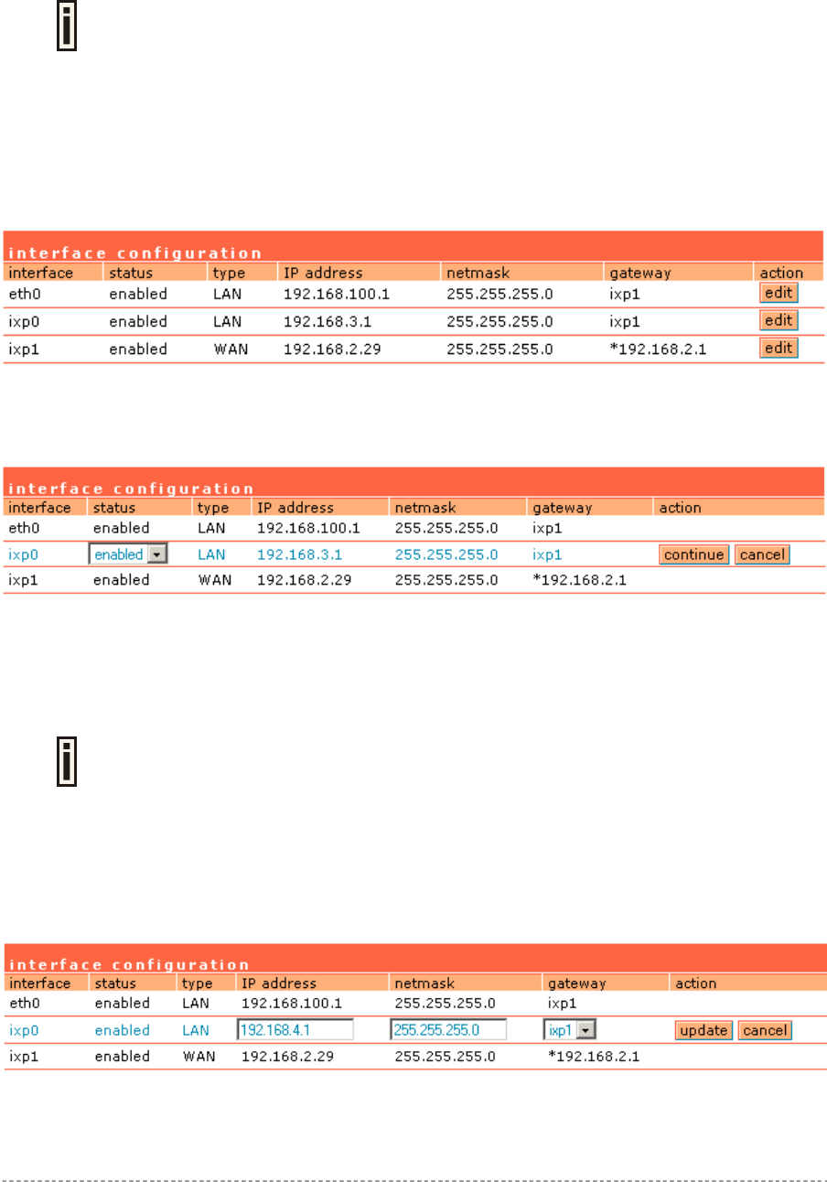
User’s Guide Chapter 7 – Reference Manual
Network Interface
Network Interface | Configuration | Interface Configuration
The interfaces eth0 and ixp0 on 2.21 firmware are bridged therefore they will be
displayed as one eth0. The screen shots in this manual will not match with ones on
your device.
The Hotspot-in-a-Box contains up to three multi-purpose network interfaces: eth0, ixp0 and ixp1.
These interfaces can be configured to work as either local area network (LAN) or wide area network
(WAN) interfaces for Access Points. LAN is used to connect hubs, switches, Access Points and
subscribers. The WAN port connects to the Internet or the service provider’s backbone network.
All these interfaces are listed in the interface configuration page. All network interfaces available in
the Hotspot-in-a-Box are shown in the following table:
Figure 39 – Interface Configuration Table
To change network interface configuration properties click the edit button in the action column. The
status can be changed now:
Figure 40 – Edit Interface Configuration Settings part.1
Interface - standard interface name. This name cannot be edited and is assigned by the operating
system during startup. Interface name cannot be changed because the hardware drivers define it.
Status – select the status of interface: [enabled/disabled].
Do not disable the interface through which you are connected to the P-560.
Disabling such interface will lose your connection to the device.
Type – network type cannot be changed. There are two possible networking types:
LAN – interface is used as local area network (LAN) gateway, and is connected to a LAN;
WAN – interface is used to access the ISP network;
Change status or leave in the default state if no editing is necessary and click the continue button.
Then the following parameters can be changed:
Figure 41 – Edit Interface Configuration Settings part.2
IP Address – specify new interface IP address [in digits and dots notation, e.g. 192.168.5.1].
Gemtek Systems Page 52
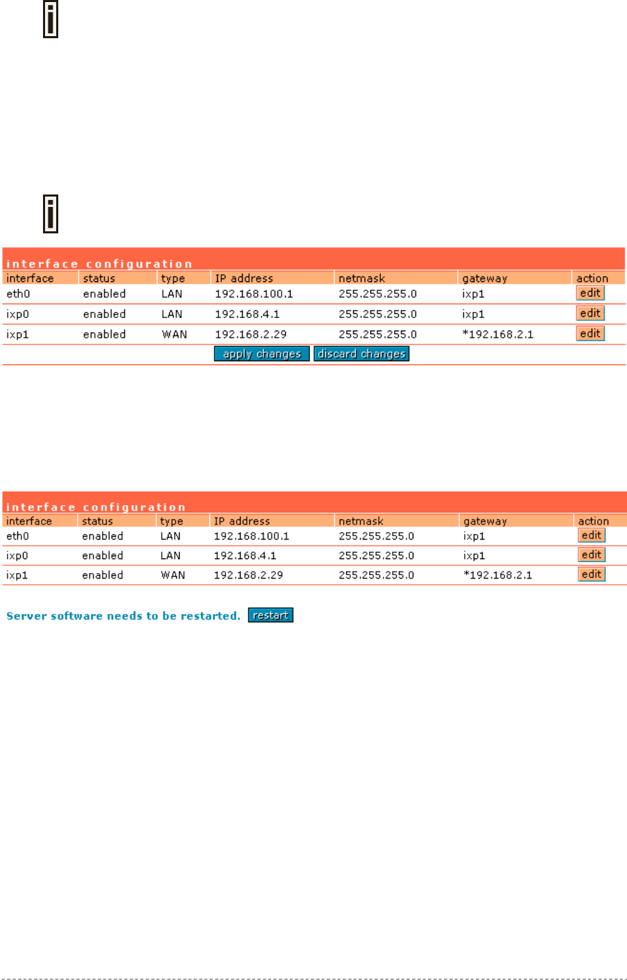
User’s Guide Chapter 7 – Reference Manual
IP address of each interface should be from a different subnet; otherwise, you will
receive an error message.
Netmask – specify the subnet mask [[0-255].[0-255].[0-255].[0-255]].These numbers are a binary
mask of the IP address, which defines IP address order and the number of IP addresses in the
subnet.
Gateway – interface gateway. For LAN type interfaces, the gateway can only be defined as WAN
interface gateway. The gateway of the WAN interface is usually the gateway router of the ISP or other
WAN network. [Default gateway is marked with ‘*’].
Update – update old values with entered ones.
The DHCP server settings will be automatically adjusted to match the new network
settings.
Figure 42 – Apply or Discard Interface Configuration Changes
Apply changes – to save all changes made in the interface configuration table at once.
Discard changes – restore all previous values.
For such general changes as interface settings change, the Hotspot-in-a-Box server needs to be
restarted. Request for restart server appears:
Figure 43 – Restart Server
Restart – Click the button to restart the server and apply the changes.
Gemtek Systems Page 53
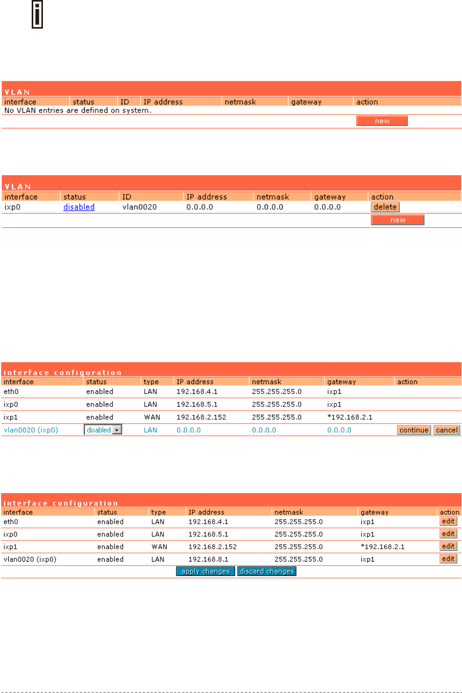
User’s Guide Chapter 7 – Reference Manual
Network Interface | Configuration | VLAN
Up to 4094 VLANs can be created in the system.
Virtual Local Area Networks (VLANs) are logical groupings of network resources. You can create your
own VLANs on your AC using the network interface | configuration | VLAN menu. By default no
VLANS are defined on the system:
Figure 44 – VLAN
To create a VLAN on the AC click the new button and enter following parameters:
Figure 45 – Create New VLAN
Interface – select interface for your VLAN network [eth0/ixp0].
Status – non-editable, by default is disabled.
ID – assign ID for your VLAN network [1 to 4094]. Client devices that associate using the ID are
grouped into this VLAN.
Other VLAN settings cannot be changed. Click on the disabled link to continue specifying settings for
your VLAN. The network interface configuration page is opened and VLAN settings are ready for
editing:
Figure 46 – Configure VLAN
Status – enable/disable your VLAN network. Select [enable] and click the continue button to
configure the VLAN settings:
Figure 47 – Configure VLAN
Type – cannot be edited, depends on selected interface for VLAN [ixp0/eth0].
IP Address – enter the network address of your VLAN [format: digits and dots].
Netmask – enter the netmask for your VLAN network [format: digits and dots].
Gateway – select gateway for VLAN network [default: ixp1].
Gemtek Systems Page 54
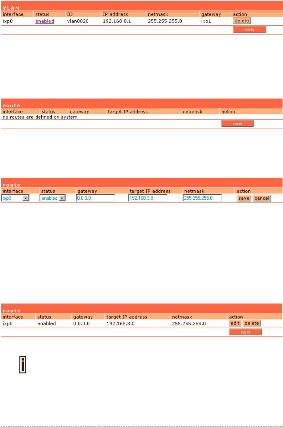
User’s Guide Chapter 7 – Reference Manual
Click the update and restart and apply changes to save your new VLAN. Check the interface |
configuration | VLAN menu for new created VLAN:
Figure 48 – Enable New VLAN
Network Interface | Configuration | Route
Under the network interface | configuration | route menu, static routes for the Ethernet interfaces
can be set. By default no static routes are defined on the system:
Figure 49 – Route
A routing rule is defined by the target subnet (target IP address and subnet mask), interface and/or
gateway where to route the target traffic. A data packet that is directed to the target network is routed
to the specified AC interface or to another gateway router. To add a new static route for the system,
click the new button under the action column and specify the following parameters:
Figure 50 – Add New Route
Status – set new static route status: [enabled/disabled].
Interface – choose device interface for the route: [eth0/ixp0/ixp1/vlan[n]].
Gateway – enter the gateway address for the route. 0.0.0.0 stands for the default gateway of the
selected interface [IP address].
Target IP Address – enter network address or host IP to be routed to [IP address].
Netmask – enter the target network netmask [dots and digits].
Save – save the new route.
Cancel – restore all previous values.
Figure 51 – Save New Route
Up to 255 static routes can be set between each interface.
Gemtek Systems Page 55

User’s Guide Chapter 7 – Reference Manual
Network Interface | Configuration | Port Forwarding
Port Forwarding is required when NAT is configured. NAT translates all internal addresses to one
official IP address (WAN IP address). With port forwarding enabled it is possible to access internal
services and workstations from the WAN interface.
Port forwarding forwards TCP or UDP traffic trough the P560 controller’s local port to the specified
remote port. Use the network interface | configuration | port forwarding menu to specify such a
port forwarding rule. By default no port forwards are defined on the controller:
Figure 52 – Port Forwarding Rules
Click the new button to add a port-forwarding rule:
Figure 53 – Add Port Forwarding Rule.
Status – select status: [enabled/disabled].
Type – select type of forwarding traffic: [TCP/UDP].
Local IP Address – P560 device interface address from which the selected traffic should be
forwarded.
Local Port – P560 device interface port from which the selected traffic should be forwarded.
Remote IP Address/Port – internal IP address and port no (LAN ports) to which the selected traffic
shall be forwarded.
Example:
Create rule as follow:
Type = TCP, local IP address/port = 192.168.2.248:8080 remote IP address/port = 1.2.3.4:8080.
With such a rule all traffic coming to port 8080 on the P560 interface local address 192.168.2.248 will
be forwarded to port 8080 on the server (host) 1.2.3.4.
Port forwarding is limited to 255 rules.
Gemtek Systems Page 56
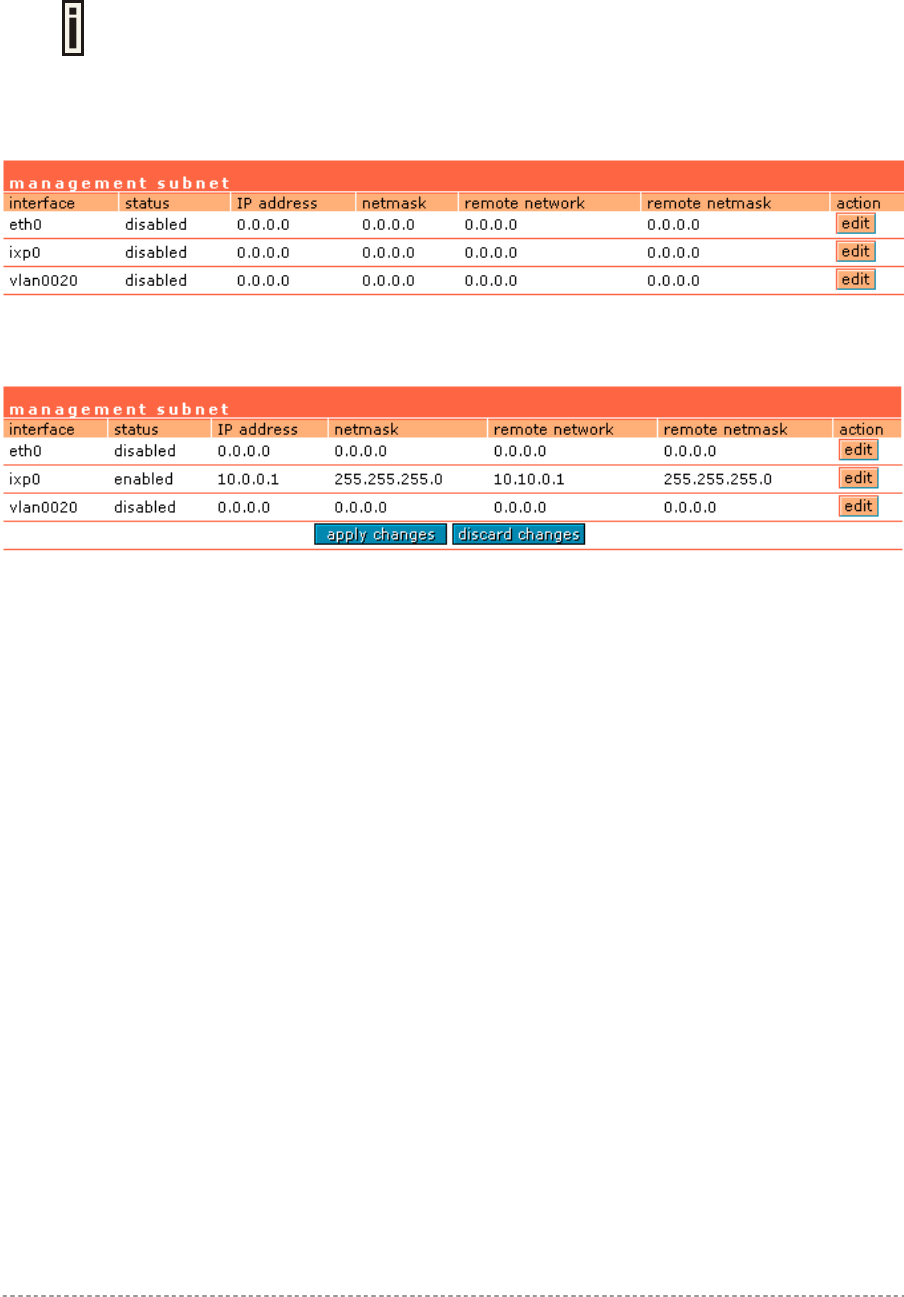
User’s Guide Chapter 7 – Reference Manual
Network Interface | Configuration | Management Subnet
Each network interface can have a management subnet. Use the network interface | configuration
| management subnet menu to configure this feature on selected interface.
When management subnet is enabled, port forwarding will NOT WORK when
connecting from IP addresses that are in the management subnet's remote
administrator's network. This is because the management subnet allows
connecting to the client computer without using port forwarding.
The administrator can enable or disable management subnet for each interface. By default no
management subnet is enabled on the controller:
Figure 54 – Management Subnet
To specify new subnet management click the edit button on the selected interface:
Figure 55 – Add Management Subnet
IP Address and Netmask – specify the IP address and netmask of the management subnet. IP
address will be set on the network interface as an alias, so you can connect to the P560 using this
address. This IP address should be used on access points as the gateway address.
Remote Network and Netmask –specify the remote network that is allowed to access the local
management subnet. Only addresses that are from the remote network will be accepted [dots and
digits].
If you do not specify any remote network all stations with IP addresses from the management LAN are
routed to the WAN port even without being authenticated.
Clients using an IP address from the management subnet can browse the Internet without
authorization, and no accounting will be done. Thus, it is strongly recommended to allow traffic only
from the administrative remote network (no 0.0.0.0/0.0.0.0 in remote specification).
Example:
Interface configuration for ixp0:
type: LAN
IP address: 192.168.3.1
netmask: 255.255.255.0
gateway: ixp1
Management subnet on ixp0:
IP address: 10.0.0.1
netmask: 255.255.255.0
remote network: 10.10.0.1
remote netmask: 255.255.255.0
Gemtek Systems Page 57
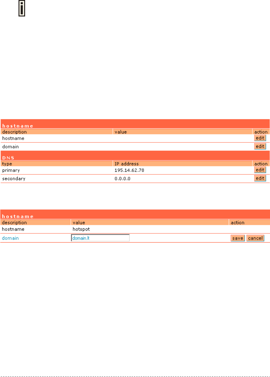
User’s Guide Chapter 7 – Reference Manual
With these settings applied, the administrator will be able to connect to devices behind the P560 on
interface ixp0, if these devices use address in the range: 10.0.0.2 ... 10.0.0.254. The administrator is
connecting via the Internet (from ixp1 interface).
The administrator’s computer can have an address from 10.10.0.1 to 10.10.0.254.
The P560 interface eth0 has two IP addresses – 192.168.3.1 and 10.0.0.1.
Please note that devices which are using 10.0.0.2. – 10.0.0.254 addresses have
access to the administrative network too!
In this example, the administrative network uses the reserved IP address (10.x.x.x) – they are not
routed in the Internet, so the administrator should setup routers in a path between the P560 and the
administrator's computer to recognize 10.x.x.x addresses and route them correctly. This is not
comfortable and sometimes it is impossible. There is a solution – the administrator can use “PPTP
client for VPN“ (or GRE tunnel) (see: Network Interface | Tunnels) to setup a tunnel between the
administrator's computer and the P560. The only addresses visible on the Internet will be the P560
WAN IP address and the administrator's computer (or router) IP address.
Network Interface | DNS
DNS (Domain Name Service) service allows AC subscribers to enter URLs instead of IP addresses
into their browser to reach the desired web site.
Figure 56 –- DNS Settings Configuration
To enter hostname and domain click the edit button in the action column and type required value:
Figure 57 – Hostname Settings
Hostname – specify the Hostname. By default hostname is not specified.
Domain – specify the Domain name. By default domain name is not specified.
Save – save modified settings.
When user is redirected to device welcome/login page, redirection will be done to:
WAN-IP, if no hostname defined;
hostname, if hostname defined, but domain empty;
hostname.domain, if hostname and domain defined.
You can enter the primary and secondary DNS servers settings under the network interface | DNS
menu:
Gemtek Systems Page 58
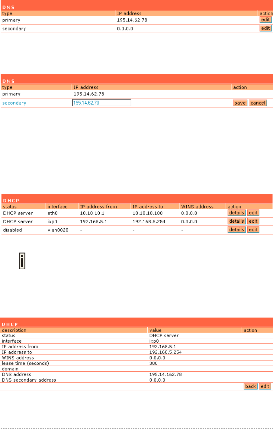
User’s Guide Chapter 7 – Reference Manual
Figure 58 – DNS Redirection Settings
The DNS server or DNS address can be obtained dynamically if DHCP, PPPoE and/or PPTP (for
DSL) service is enabled. To add DNS server manually click the edit button in the action column and
type in the DNS server’s IP address:
Figure 59 – Edit DNS Redirection Settings
IP address – enter the primary or secondary DNS server’s IP address [in digits and dots notation].
Save – click to save the new DNS server’s settings.
Network Interface | DHCP
The P560 controller can act as a DHCP server and/or as a DHCP relay gateway. The DHCP
(Dynamic Host Configuration Protocol) service is supported on the LAN interfaces [eth0/ixp0/vlan[n]].
This service enables clients on the LAN to request configuration information, such as an IP address,
from a server. This service can be viewed in the following table:
Figure 60 – DHCP Configuration
By default the AC is configured to act as a DHCP server.
Each LAN interface runs a different instance of the DHCP service. This service is configured by
defining an IP address range and WINS address for client workstations. Other settings, such as the
default gateway and DNS server address are configured automatically according to the interface
settings.
To see the complete DHCP service configuration, click the details button in the action column:
Figure 61 – DHCP Settings Details
Gemtek Systems Page 59
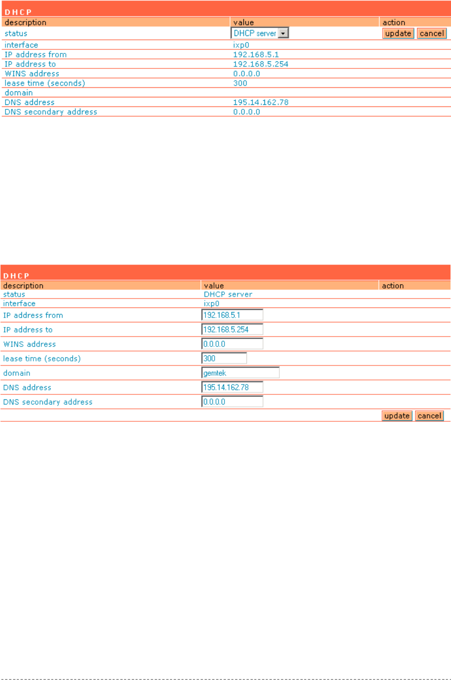
User’s Guide Chapter 7 – Reference Manual
To edit the DHCP service configuration [DHCP server/DHCP relay], click the edit button in the action
column:
Figure 62 – Edit DHCP Configuration Settings
Status – select status from drop-down menu:
Disabled – disable the DHCP service on the selected interface
DHCP Server – enabled by default
DHCP Relay – to route DHCP through the external server, enable relay service
Case 1 Configure the DHCP server
Select the interface on which you want to configure the DHCP service [eth0/ixp0/vlan[n]]. Select the
DHCP server and click the update button specify the DHCP server parameters:
Figure 63 – Edit DHCP Server Settings
IP Address from/IP Address to – specify the IP address range supported for the DHCP service
[mandatory fields].
WINS Address (Windows Internet Naming Service) – specify service IP address if it is available on
the network [dots and digits].
Lease Time – specify the IP address renewal in seconds [1-1000000].
Domain – specify DHCP domain name [optional, 1-128 sting].
DNS address – specify the DNS server’s IP address [in digits and dots notation].
DNS secondary address – specify the secondary DNS server’s IP address [in digits and dots
notation].
Case 2 Configure the DHCP relay
Select the interface on which you want to configure the DHCP service [eth0/ixp0/vlan[n]]. Select the
DHCP relay and click the update button specify the DHCP relay parameters:
Gemtek Systems Page 60
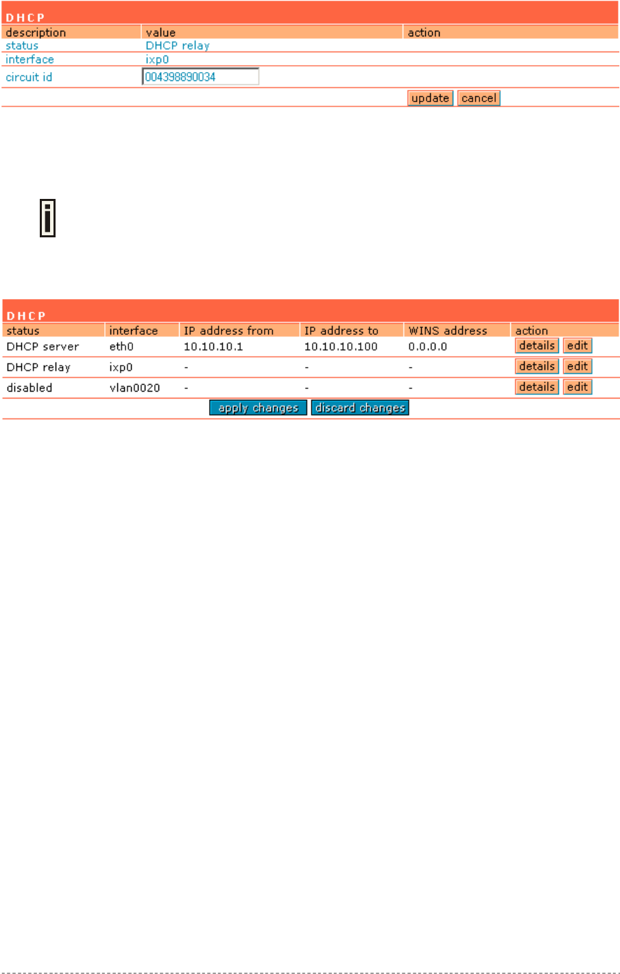
User’s Guide Chapter 7 – Reference Manual
Figure 64 – Edit DHCP Relay Settings
Circuit ID – the unique DHCP relay parameter [optional, by default the MAC address of the device
WAN interface is used].
If DHCP relay service is selected, the default WAN gateway is used automatically.
Update – to update entered values, the following screen appears:
Figure 65 – Apply or Discard DHCP Server Settings
Apply Changes – to save entered new DHCP settings.
Discard Changes – to restore previous values.
Gemtek Systems Page 61

User’s Guide Chapter 7 – Reference Manual
Network Interface | RADIUS
RADIUS is an authentication and accounting system used by many Internet Service Providers (ISP).
RADIUS enables ISPs to maintain a very large database of users. By using RADIUS, service
providers can implement policy-based management of their subscribers’ base. RADIUS also helps
ISPs to collect statistical data about their subscribers (e.g. amount of time, amount of transferred
bytes, and session time).
Use the RADIUS (Remote Authentication Dial In User Service) menu to set-up the following RADIUS
settings:
RADIUS Settings – general RADIUS settings configuration (e.g. NAS server ID, servers
timeouts)
RADIUS Servers – up to 32 different RADIUS servers’ configuration (accounting and
authentication servers)
WISP (Wireless Internet Service Provider) – specify WISP domain for RADIUS server
Proxy – configure the P560 to act as RADIUS proxy server.
Accounting Backup – backup the RADIUS subscribers accounting information.
In the Appendix tables: E) Standard RADIUS Attributes and Vendor Specific
Attributes Hotspot operators will find the required standard RADIUS attributes for
setting up the RADIUS system.
Gemtek Systems Page 62
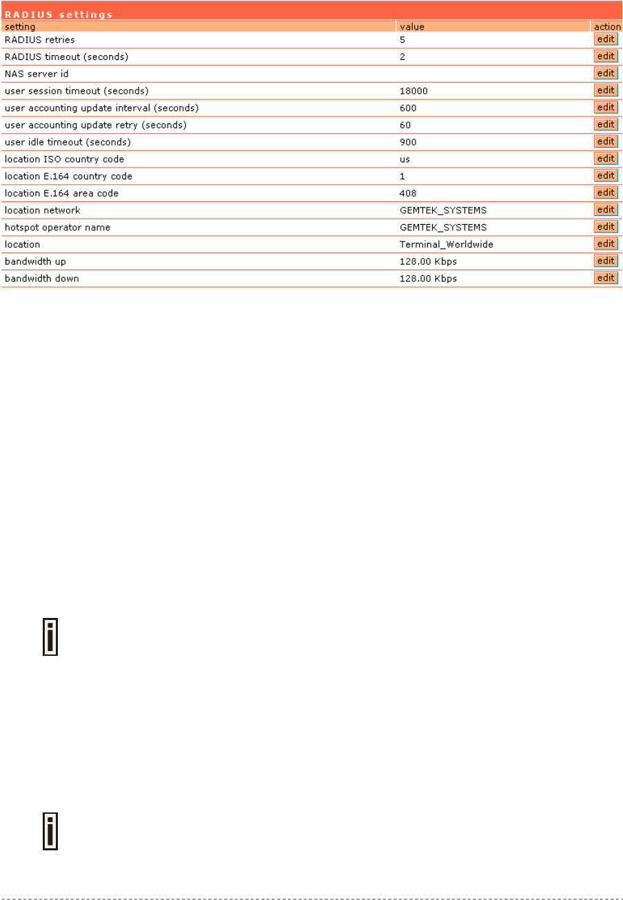
User’s Guide Chapter 7 – Reference Manual
Network Interface | RADIUS | RADIUS Settings
General RADIUS settings are configured using the RADIUS settings menu under the network
interface:
Figure 66 – RADIUS Settings Configuration
RADIUS Retries – retry count of sending RADIUS packets before giving up.
RADIUS Timeout – maximum amount of time before retrying RADIUS packets [sec].
NAS Server ID – name of the RADIUS client.
User Session Timeout - amount of time from the user side (no network carrier) before closing the
connection [sec].
User Accounting Update - period after which server should update accounting information [sec].
User Accounting Update Retry – retry time period in which server should try to update accounting
information before giving up [sec].
User Idle Timeout - amount of user inactivity time, before automatically disconnecting user from the
network [sec].
Location ISO Country code – location ID attribute, country code according ISO standards [string].
Location E.164 Country code – location ID attribute, country code according E.164 specification.
Location E.164 Area code – location ID attribute, area code according E.164 specification.
See the Location ID and ISO Country codes for your country in the Appendix: F)
Location ID and ISO Country Codes.
Location Network – location ID attribute, network name [string].
Hotspot Operator Name – location name attribute, operator’s name [string].
Location – location name attribute, textual description of the location [string].
Bandwidth Up – maximum bandwidth up at which corresponding user is allowed to transmit [bps].
Bandwidth Down – maximum bandwidth down at which corresponding user is allowed to receive
[bps].
User can check its available bandwidth in the logout page statistics.
Gemtek Systems Page 63
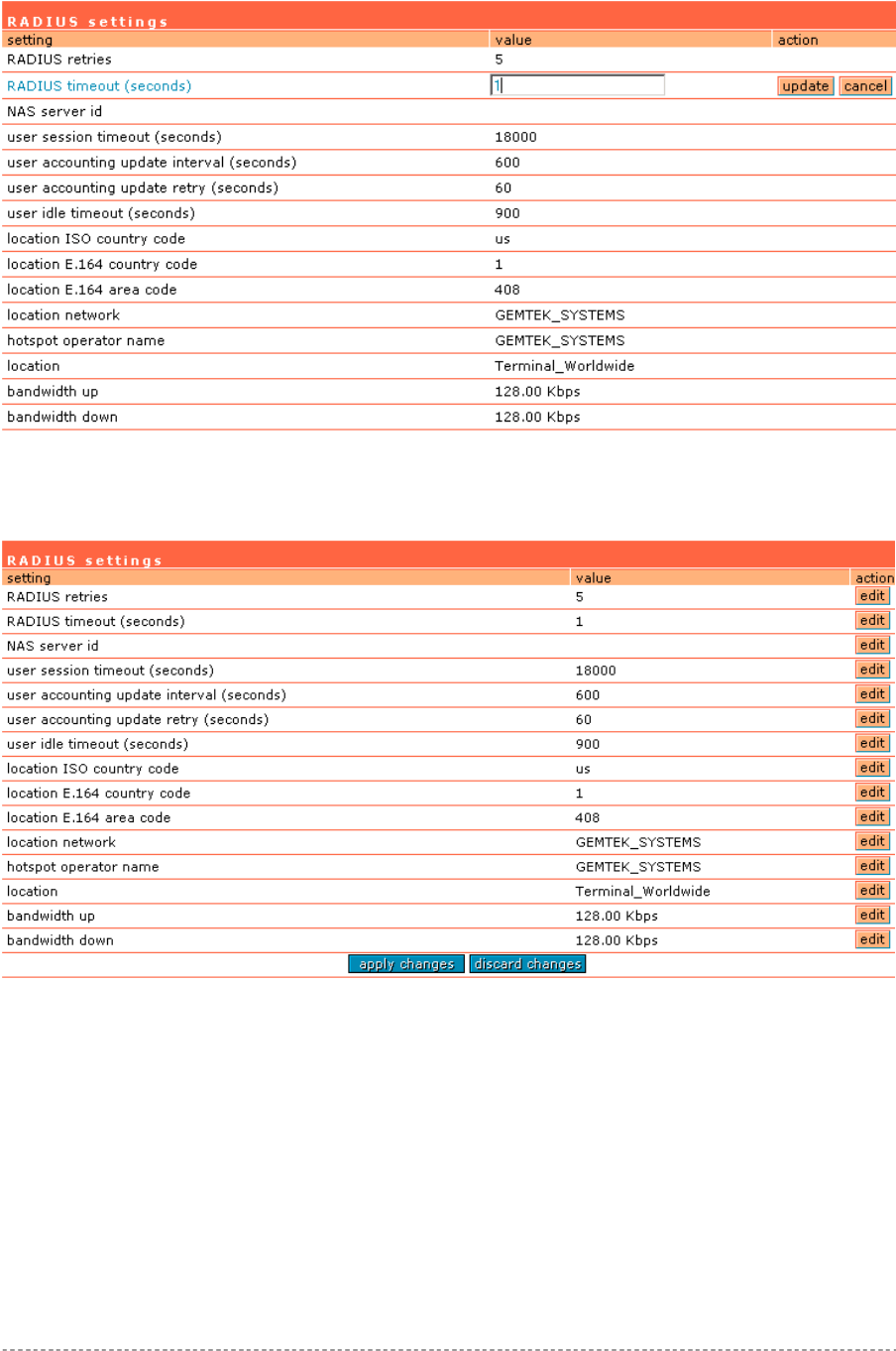
User’s Guide Chapter 7 – Reference Manual
Each setting in this table can be edited. Select RADIUS setting you need to update, click the edit next
to the selected setting and change the value:
Figure 67 – Edit RADIUS Settings
Use the update button to update to an entered value. Now select another RADIUS setting to edit, or
apply changes and restart the server if the server configuration is finished:
Figure 68 – Apply or Discard RADIUS Settings
Apply Changes – click if RADIUS settings configuration is finished.
Discard Changes – restore all previous values.
Gemtek Systems Page 64
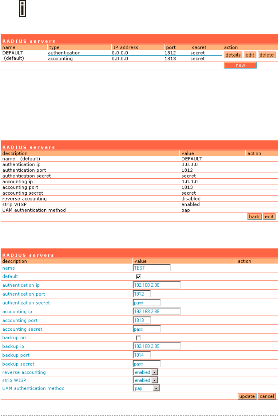
User’s Guide Chapter 7 – Reference Manual
Network Interface | RADIUS | RADIUS Servers
Up to 32 different RADIUS servers can be configured under the RADIUS servers
menu.
By default, one RADIUS server is specified for the system:
Figure 69 – RADIUS Servers Settings
New – add new RADIUS server.
Details – click on details to get more information about RADIUS server settings.
Edit – edit selected RADIUS server settings.
Delete – remove selected RADIUS server.
To view complete RADIUS server settings, click the details button in the action column:
Figure 70 – RADIUS Server's Details
To edit RADIUS server click the edit button:
Gemtek Systems Page 65

User’s Guide Chapter 7 – Reference Manual
Figure 71 – Add New RADIUS Server
Name – specify the new RADIUS server name.
Default – check the check box to make the selected RADIUS the default server.
Authentication IP – authentication RADIUS server IP address [dots and digits].
Authentication Port – specify the network port used to communicate with RADIUS [1-65535].
The port default value of 1812 is based on RFC 2138 "Remote Authentication Dial-
in User Service (RADIUS)".
Authentication Secret – shared secret string that is used to encrypt data frames used for
authentication server.
Accounting IP – accounting RADIUS server IP address [dots and digits].
Accounting Port – specify the network port used to communicate with RADIUS [1-65535].
Accounting Secret – shared secret string that is used to encrypt data frames used for accounting
server.
Backup IP – backup RADIUS server IP address [dots and digits].
Backup Port – specify the network port used to communicate with RADIUS [1-65535].
Backup Secret – shared secret string that is used to encrypt data frames used for backup server.
Shared secret must be the same on RADIUS server and RADIUS client.
Reverse Accounting – [enabled/disabled]. The RADIUS accounting request contains Acc-Input-
Octets and Acc-Output-Octets attributes. The interpretation of these attributes according the
RFC2866 is relative to the point of view. If this point is at the AC - Acct-Input* attributes should contain
the bytes/packets received at AC port from the client and Acct-Output* attributes should contain
bytes/packets sent from AC port to the client. If we move this point to the client - we will get the
reversing of Acct-Input* and Acct-Output* attributes values. The Acct-Input* then should contain
bytes/packets received from AC, what is bytes/packets that AC sent to the user in AC point of view
and what was Acct-Output*.
The AC implementation of RADIUS accounting request is at the client point of view
(reverse accounting is disabled).
The value "disabled" means that Acct-Input* RADIUS attributes will contain bytes/packets sent to
the client and Acct-Output* RADIUS attributes will contain bytes/packets received from the client
during the curse of service being provided.
The value "enabled" means that info in the Acct-Input* and Acct-Output* RADIUS attributes will be
swapped (reversed). That is the Acct-Input* will contain bytes/packets received from the client and the
Acct-Output* will contain bytes/packets sent to the client.
Strip WISP – [enabled/disabled] select ‘enabled' if you want to strip WISP domain name before
sending it to the RADIUS server. Stripping means removing everything before the “/” character
including character itself for such user name login format like: “WISPdomain/username”.
Select “disabled” if you need to send the user login name to RADIUS server unmodified. Some
RADIUS servers can be configured in such way that requires full-unmodified user name to be sent.
UAM authentication method – select authentication method from drop-down menu:
PAP – Password Authentication Protocol
CHAP – Challenge Handshake Authentication Protocol
MSCHAP1 – Microsoft Challenge Handshake Authentication Protocol version 1
MSCHAP2 – Microsoft Challenge Handshake Authentication Protocol version 2
Gemtek Systems Page 66
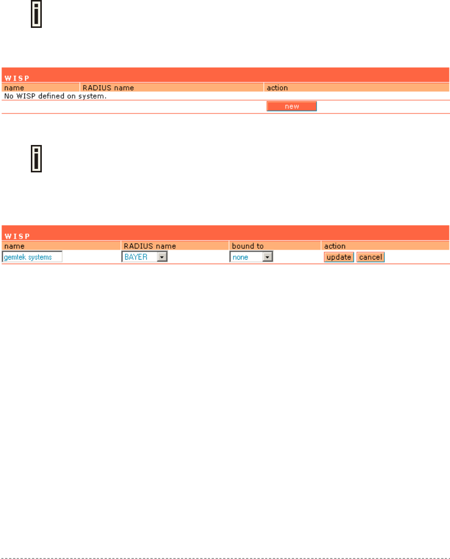
User’s Guide Chapter 7 – Reference Manual
Update – add new specified RADIUS server.
Cancel – restore all previous values.
After adding a new RADIUS server or editing an existing one, the following controls appears:
Apply Changes – save changed configuration.
Discard Changes – discard all changes.
Restart – after applying changes to the system, you should restart the controller to make applied
changes work.
Network Interface | RADIUS | WISP
Up to 32 WISP entries can be defined using the network interface | RADIUS |
WISP menu.
Different WISPs (Wireless Internet Service Providers) can be associated with appropriate RADIUS
servers and device interfaces using the network interface | RADIUS | WISP menu:
Figure 72 – WISP Menu
Hotspot subscribers user name format from WISP table is as follows:
username@WISPdomain
WISPdomain/username
New – click to define WISP for RADIUS server.
Figure 73 – Define New WISP
Name – new WISP domain name [string, up to 256 symbols, no space, dot or dash allowed].
RADIUS Name – select RADIUS for new WISP from list box [non editable].
Bound To – select the WISP binder interface [none/eixp0/ixp1/ixp2/vlan[n]]. The WISP can be
associated with appropriate device interface.
Update – system with new WISP.
Cancel – restore all previous values.
Network Interface | RADIUS | Proxy
The P560 (AC) can forward the RADIUS authentication and accounting requests from Access Point
(AP) to the real RADIUS server. To configure the RADIUS proxy, follow the steps:
Step 1 Connect the Access Point to any LAN port available on the Access Controller
(P560). The AP should be in the bridge mode.
Step 2 Using the network interface | RADIUS | proxy menu configure the RADIUS proxy
parameters: RADIUS authentication port (UDP), RADIUS accounting port (UDP) -
different from authentication port and Accounting detection timeout:
Gemtek Systems Page 67

User’s Guide Chapter 7 – Reference Manual
Figure 74 – RADIUS Proxy Settings
RADIUS Proxy Status – select [enabled] to enable the RADIUS proxy feature [enabled/disabled].
Authentication Port – specify the port on AC for listening the RADIUS authentication packets. The
AC RADIUS proxy authentication port will accept only RADIUS authentication packets [1-65535,
default: 1812].
Accounting Port – specify the port on AC for listening the RADIUS accounting packets. The AC
RADIUS proxy accounting port will accept only RADIUS accounting packets [1-65535, default: 1813].
Detection Timeout – specify the RADIUS proxy accounting detection timeout in seconds. The AC will
wait the specified period for accounting packet after the authentication request was got [0-3600].
The authentication RADIUS proxy port should differ from the accounting port.
Step 3 Configure the AP to send the RADIUS authentication and accounting packets to
the AC LAN IP address and UDP ports which are configured on AC RADIUS proxy
configuration.
Step 4 The RADIUS secrets on AC should be set to value, which is good at the real
RADIUS server for which the following packet will be forwarded.
Such preconfigured AC will act as RADIUS proxy and will forward the RADIUS authentication and
accounting packets from AP according WISP and RADIUS server settings in the AC configuration
without any modification.
Gemtek Systems Page 68
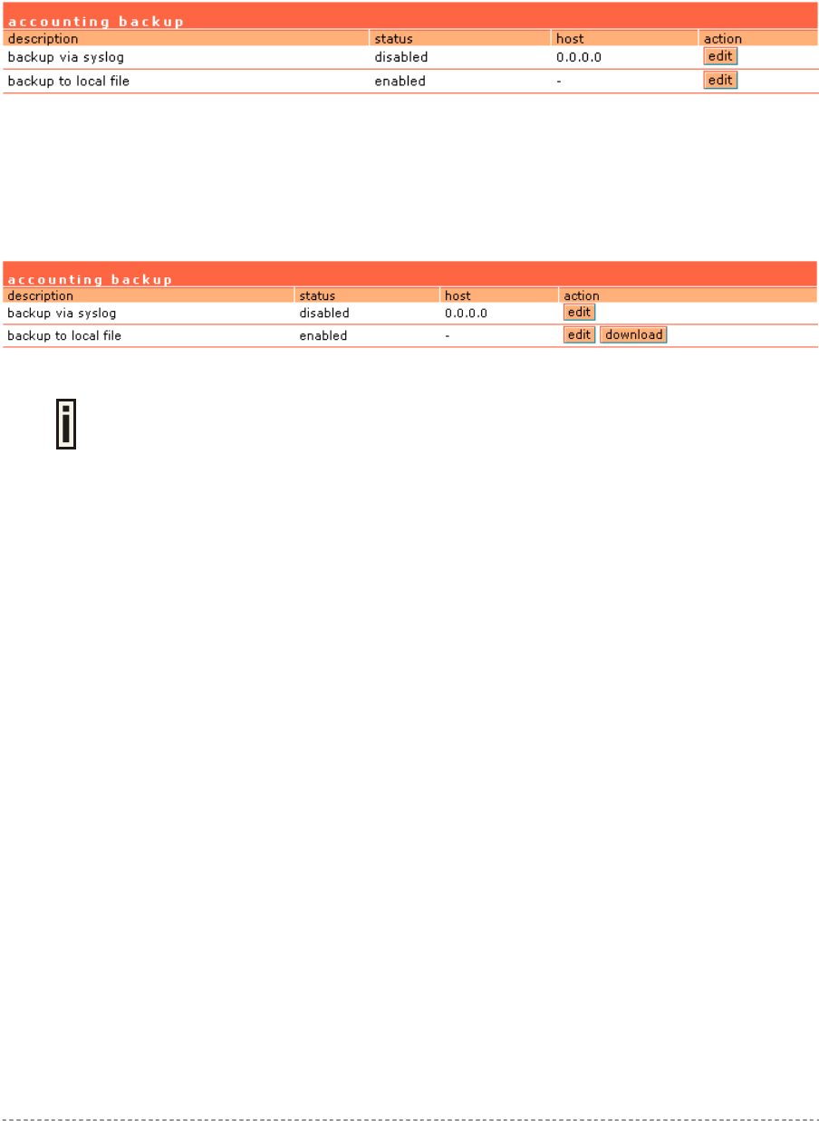
User’s Guide Chapter 7 – Reference Manual
Network Interface | RADIUS | Accounting Backup
The administrator can backup the hotspot subscribers’ RADIUS accounting information in two ways:
Via syslog protocol to the specified host
Download to the selected location (e.g. on your PC)
Use the network interface | RADIUS | accounting backup menu:
Figure 75 – Accounting Backup
Backup via syslog – enable this type to send the RADIUS accounting information via syslog protocol
to the specified host [enable/disable] and note that the Host IP specification is obligatory.
Host – enter host IP address where to send accounting backup messages.
Backup to local file – enable this option, and the download button appears:
Download – click the button to download the accounting information file to your selected location.
Both types of accounting backup can be enabled.
Gemtek Systems Page 69
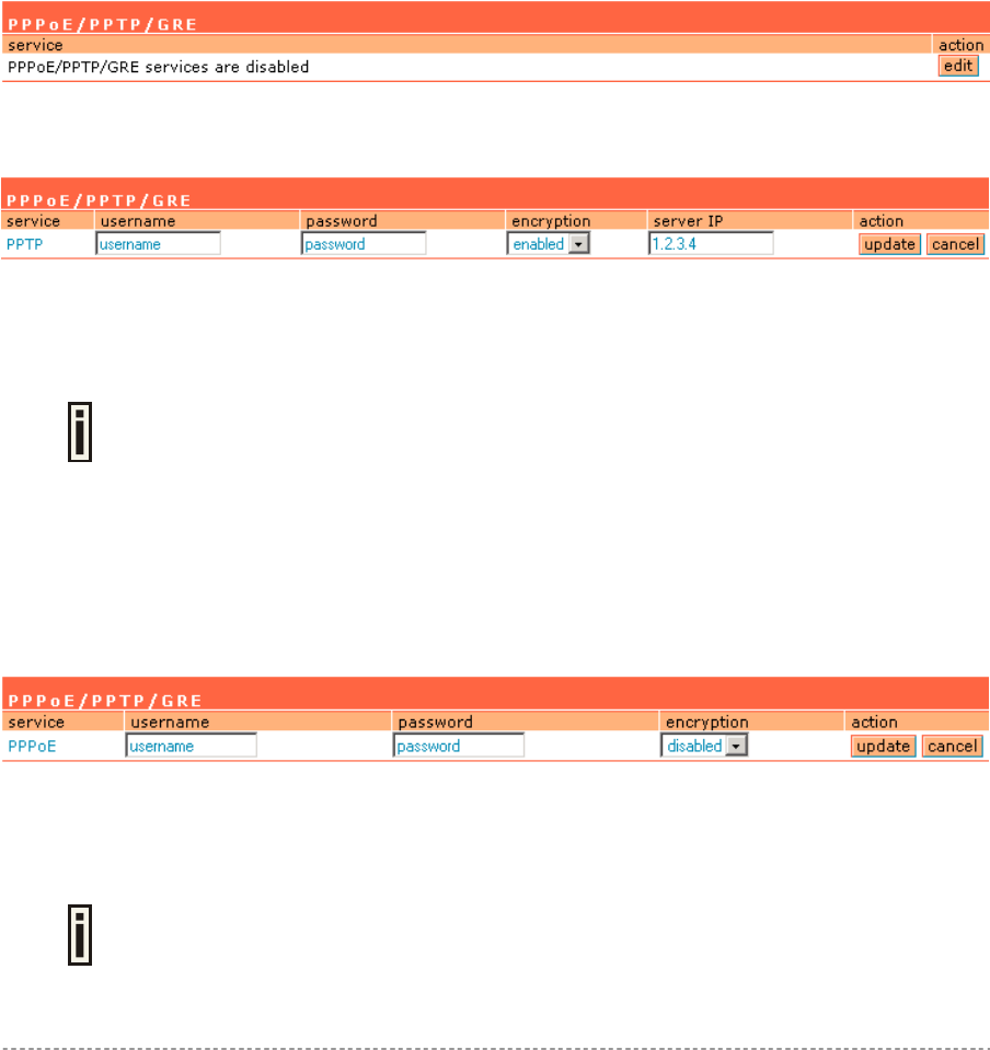
User’s Guide Chapter 7 – Reference Manual
Network Interface | Tunnels
This chapter describes the configuration of VPN tunnels. VPN tunnels can be used to secure
management and AAA traffic between the hotspot network and the network operation center of the
operator.
The Gemtek Systems Access Controllers support PPTP and GRE tunnels. Furthermore PPP (Point-
to-Point Protocol) can be use to authenticate the AC to a authentication server and to assign IP
settings to the WAN port of the AC.
Network Interface | Tunnels | PPPoE/PPTP/GRE
Use the network interface | tunnels | PPPoE/PPTP/GRE menu to connect to ISP via PPTP, PPPoE
or GRE tunnel. All traffic will be sent via this tunnel.
Default gateway specified in network interface | configuration page will not be used, because all
Internet traffic will be sent/received via the specified PPTP, PPPoE or GRE server (tunnel).
By default no services are available on the controller:
Figure 76 – PPPoE/PPTP/GRE for DSL
To specify PPTP tunnel for your controller click the edit button and enter the following:
Figure 77 – Specify PPTP Tunnel
Service – select service PPTP.
Username – enter username to connect to the server [text string, can not be empty].
The same username should be configured on the PPTP server.
Password – enter password by which user should be authenticated [text string, can not be empty].
Encryption – enables use of MPPE encryption.
Server IP – PPTP server IP address.
To specify PPPoE tunnel for your controller click the edit button and enter the following:
Figure 78 – Specify PPPoE Tunnel
Service – select service PPPoE.
Username – enter username to connect to the server [text string, can not be empty].
The same username should be configured on the PPPoE server.
Password – enter password by which user should be authenticated [text string, can not be empty].
Gemtek Systems Page 70
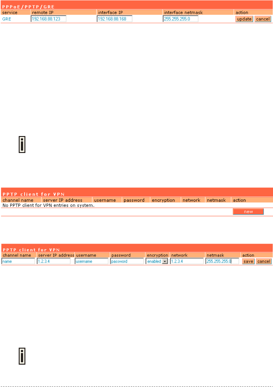
User’s Guide Chapter 7 – Reference Manual
Encryption – enables use of MPPE encryption.
When PPPoE tunnel is used, then no server IP is required - broadcast address will be used.
To specify GRE tunnel for your controller click the edit button and enter the following:
Figure 79 – Specify GRE Tunnel
Service – select service GRE.
Remote IP – IP address of GRE tunnel endpoint [IP address].
Interface IP – enter the IP address of GRE interface [IP address].
Interface Netmask – enter the netmask of GRE interface [netmask].
Network Interface | Tunnels | PPTP Client for VPN
PPTP Client for Virtual Private Network (VPN) is designed to secure the management and AAA
traffic as well as to establish a VPN tunnel connection to the network operation center, for example
when the administrator needs to reach access points behind the P560 from his workstation.
Should be used with Management Subnet feature, otherwise the firewall will not
be enabled to reach anything behind the P560.
Only specific traffic will be sent to the tunnel with everything else sent using the default gateway
specified on network interface | configuration page.
By default no PPTP clients are defined for the controller:
Figure 80 – PPTP Client for VPN
To specify new tunnel for your AC, click the new button:
Figure 81 – Add PPTP Client
Channel Name – enter free form string for tunnel identification (for user only).
Server IP Address - IP address [can not be empty].
Username – enter username to connect to the PPTP server [text string, can not be empty].
Password – enter password by which user should be authenticated [text string, can not be empty].
Encryption – enables use of MPPE encryption.
Network/Netmask – enter remote network settings [format: dots and digits].
Up to 16 VPN entries can be set.
Gemtek Systems Page 71
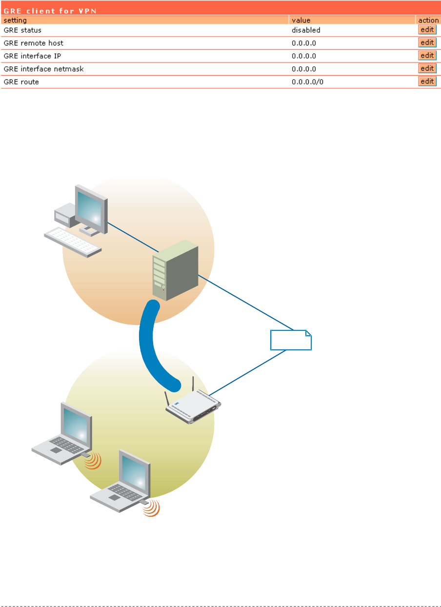
User’s Guide Chapter 7 – Reference Manual
Network Interface | Tunnels | GRE Client for VPN
GRE (Generic Routing Encapsulation) tunnel is one of the solutions for tunneling private network over
the TCP/IP connection (e.g. PPTP, L2TP, PPPoE). GRE tunnel does not use encryption. It only
encapsulates data and sends it over the Internet. So the administrator should take care that no
unencrypted private information is going through the GRE tunnel. By default the GRE tunnel is
disabled on the AC:
Figure 82 – GRE Tunnel
See the following example to understand GRE settings.
Example:
P-560
GRE Serve
r
Internet
Net A
Net B
192.168.82.0/24
WLAN:
192.168.3.0/24
GRE Device IP:
211.139.210.168
LAN:
192.168.82.16
WAN:
211.139.210.123
GRE Tunnel
NMS:
IP: 192.168.82.137
Router: 192.168.82.16
Figure 83 – GRE Tunnel
For example, there are 2 internal networks: network A and B, and intermediate network - Internet.
Gemtek Systems Page 72
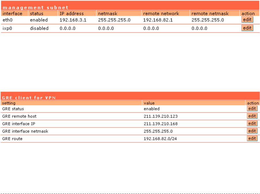
User’s Guide Chapter 7 – Reference Manual
Network A (administrator's computer with Network Management System); we shall call this network
(192.168.82.0/24) “Net A”.
Network: 192.168.82.0
Netmask: 255.255.255.0
Router: 192.168.82.16
GRE server has two interfaces, LAN and WAN:
LAN IP: 192.168.82.16
WAN IP: 211.139.210.123
Settings in GRE tunnel page:
GRE Remote Host: 211.139.210.123
GRE Route: 192.168.82.0/24
Network B has subscribers on wireless P-560 interface (eth0) we shall call this network
(192.168.3.0/24) “Net B”:
Network: 192.168.3.0
Netmask: 255.255.255.0
Router: 192.168.3.1
Where GRE interface (WAN IP of AC) is 211.139.210.168.
Settings in GRE tunnel page:
GRE Device IP: 211.139.210.168
GRE Device Netmask: 255.255.255.0
Settings in Management Subnet page on eth0 interface (network interface | configuration |
management subnet menu) of AC:
IP Address: 192.168.3.1
Netmask: 255.255.255.0
Remote Network: 192.168.82.1
Remote Netmask: 255.255.255.0
Figure 84 – Management Subnet Settings
As far as the Internet is concerned, we assume that it will pass any packet sent from A to B and vice
versa.
With settings from above, the administrator from Net A will be able to access clients on Net B through
the GRE tunnel between the GRE server and the GRE interface of AC.
Use the edit button next to a setting to change its value:
Figure 85 – GRE Settings
GRE Status – select one: [enabled or disabled].
Remote Host – IP address of GRE tunnel endpoint [IP address].
GRE Interface IP – enter the IP address of GRE interface [IP address].
Gemtek Systems Page 73

User’s Guide Chapter 7 – Reference Manual
GRE Interface Netmask – enter the netmask of GRE interface [dots and digits].
GRE interface IP/Netmask settings is important when configuring the GRE server.
GRE Route – this is the destination network for the GRE tunnel in the combined node/subnet format
[IP address/N].
The /N stands for the number of bits that are in the network address. There are 32 bits, so we have
32-N bits left that are part of our network. The first N bits of x.x.x.x correspond to x.0.0.0 when N=8,
our network address, and the netmask is 255.0.0.0 (when N=8).
bits netmask
/32 255.255.255.255
/31 255.255.255.252
/30 255.255.255.248
… …
/26 255.255.255.192
/25 255.255.255.128
/24 255.255.255.0
… …
/16 255.255.0.0
… …
/8 255.0.0.0
… …
/0 0.0.0.0
Gemtek Systems Page 74
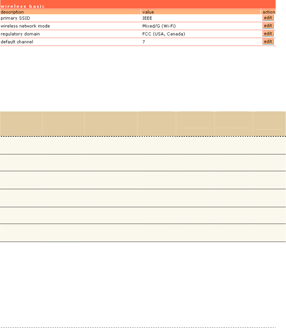
User’s Guide Chapter 7 – Reference Manual
Network Interface | Wireless
The Hotspot-in-a-Box has the wireless interface (eth0) and can act as the Access Point. Using the
network interface | wireless menu, the system administrator can create a wireless network
infrastructure (WDS), set the wireless basic settings (SSID, network mode: 802.11b/802.11g,
regulatory domain/channel), set the advanced settings (layer 2 isolation, SSID broadcasting), select
the security methods (WEP/WPA) or create the access control list (ACL).
Network Interface | Wireless | Basic
Use the network interface | wireless | basic menu to configure such wireless settings as SSID,
network mode or regulatory domain/channel. Click the edit button on the setting you need to change:
Figure 86 – Basic Wireless Settings
Primary SSID – is a unique name for your wireless network. It is case sensitive and must not exceed
126 characters. The default SSID is "P560" but you should change this to a personal wireless network
name. The SSID is important for clients when connecting to the access point. All client stations must
have their client SSID settings configured and must use the same SSID.
Wireless Network Mode – select wireless network mode for optimal performance, from the drop
down list. Each wireless network mode includes basic and supported rates.
Wireless
Network
Mode
Basic Rates
(Mbps)
Supported
Rates (Mbps)
Preamble
Settings
Non ERP
Protection
Slot
Settings
CWmin
B only 1, 2, 5.5, 11 - Dynamic Dynamic Long
31
G (Wi-Fi)* 1, 2, 5.5 6,
11, 12, 24 9, 18, 36, 48, 54 Dynamic Dynamic Dynamic 15
B (Wi-Fi) 1, 2 5.5, 11 Dynamic Dynamic Long
31
Mixed/G
(Wi-Fi) 1, 2, 5.5, 11 6, 9, 12, 18, 24,
36, 48, 54
Dynamic Dynamic Dynamic 15
Mixed 1, 2, 6, 12,
24
5.5, 9, 11 18, 36,
48, 54
Dynamic Dynamic Dynamic 15
Mixed
(Wi-Fi)
1, 2, 5.5, 6,
11, 12, 24 9, 18, 36, 48, 54 Dynamic Dynamic Dynamic 15
* This mode enforces rejection of non-ERP capable clients.
Data Rates – the range of data transmission rates supported by a device and they are measured
in megabits per second (Mbps).
Basic Rates – are the list of rates that are mandatory for another radio to communicate with.
These rates are used for packets such as, control packets and broadcast packets.
Supported Rates – are the list of rates that the radio is capable of running.
Preamble Settings – indicates Dynamic mode that allows mixing Long Preamble only clients
with Short Preamble capable clients. If both 802.11g clients and Long Preamble only clients are
Gemtek Systems Page 75

User’s Guide Chapter 7 – Reference Manual
associated, the Access Point sets the Short Preamble capability bit to 0 and Long Preamble is
used. In all other cases, the Short Preamble capability bit is set to 1 and Short Preamble is used.
CWmin – indicates contention window size minimum.
NonERP Protection – indicates Dynamic mode what means that NonERP protection bit is set to
0 or 1 whether NonERP BSSs or stations are associated to AP or not.
Slot Settings – indicates Dynamic or Long mode:
Dynamic mode allows mixing 802.11b only clients with Short Slot capable clients. If only
802.11g Short Slot capable clients are associated, 802.11a slot timing is used and the Short
Slot capability bit is set. If any non-802.11g/Short Slot capable clients are associated, the
access point switches back to 802.11b slot timing and clears the Short Slot capability bit.
Long mode indicates that the access point never sets the Short Slot capability bit in the
Beacons, Probes and Association Responses. Clients should therefore not use it.
Regulatory Domain – select the domain according to your country.
The full frequency range of the 2.4 GHz ISM band is not permitted for use in all countries. Depending
on your selection of regulatory domains, the available frequency channels will vary.
Before changing radio settings manually verify that your settings comply with
government regulations. At all times, it will be the responsibility of the end-user to
ensure that the installation complies with local radio regulations. Refer to the
Appendix: C) Regulatory Domain/Channels.
Default Channel – select the default channel. Channels list will vary depending on selected
regulatory domain.
Multiple frequency channels are used to avoid interference between nearby access points. If you wish
to operate more than one access point in overlapping coverage areas, we recommend a distance of
at least four channels between the chosen channels. For example, for three Access Points in close
proximity choose channels 1, 6 and 11.
Gemtek Systems Page 76

User’s Guide Chapter 7 – Reference Manual
Network Interface | Wireless | Advanced
Use the network interface | wireless | advanced menu to configure the layer 2 client isolation, SSID
broadcasting or threshold values or wireless card output power:
Figure 87 – Advanced Wireless Setting
Layer 2 Isolation – Layer 2 wireless client separation. Connected clients with user isolation function
enabled cannot access each other directly. The clients are isolated from each other using their MAC
addresses [enabled/disabled].
SSID Broadcasting – when enabled, your AP’s SSID is visible in the networks list while scanning the
available networks for wireless client. When disabled, the AP’s SSID is not visible in the available
network list (SSID is not broadcasted with its Beacons) [enabled/disabled]. By default the SSID
broadcasting is enabled.
Fragmentation Threshold –the fragmentation threshold, specified in bytes, determines whether
packets will be fragmented and at what size. On an 802.11 wireless LAN, packets exceeding the
fragmentation threshold are fragmented, i.e., split into, smaller units suitable for the circuit size.
Packets smaller than the specified fragmentation threshold value are not fragmented [[256-2346]
default: 2346 (2346 means that fragmentation is disabled)].
RTS Threshold – when set, this setting specifies the maximum packet size beyond which the
Wireless LAN Card invokes its RTS/CTS mechanism. Packets that exceed the specified RTS
threshold trigger the RTS/CTS mechanism. The NIC transmits packets smaller than this threshold
without using RTS/CTS [[0-2347] default: 2347 (2347 means that RTS is disabled)].
Output Power – the wireless card transmission output power in dBm [0-31].
Antenna Gain (dBi)– is the gain of the connected antenna in relation to an isotropic radiated power.
Total output power (wireless output power plus antenna gain) should comply with
local radio regulations. Refer to the Appendix: C) Regulatory Domain/Channels.
Network Interface | Wireless | Security
Secure your wireless network use one of the available encryption methods:
WEP (Wired Equivalent Privacy) with 64-bit/128-bit encryption
WPA (Wi-Fi Protected Access) with pre shared key or with RADIUS server
The WPA is a far stronger protocol and fixes the weaknesses in WEP. To enable the WPA security for
your WLAN you will need:
An access point that has WPA support (e.g. Gemtek Systems P-560)
A wireless network card that has WPA drivers available
A mobile client that supports WPA and your operating system
To configure the WPA with pre-shared key security on the P-560 use the network interface |
wireless | security menu, select the WPA with pre-shared key security method and enter the pre-
shared key:
Gemtek Systems Page 77
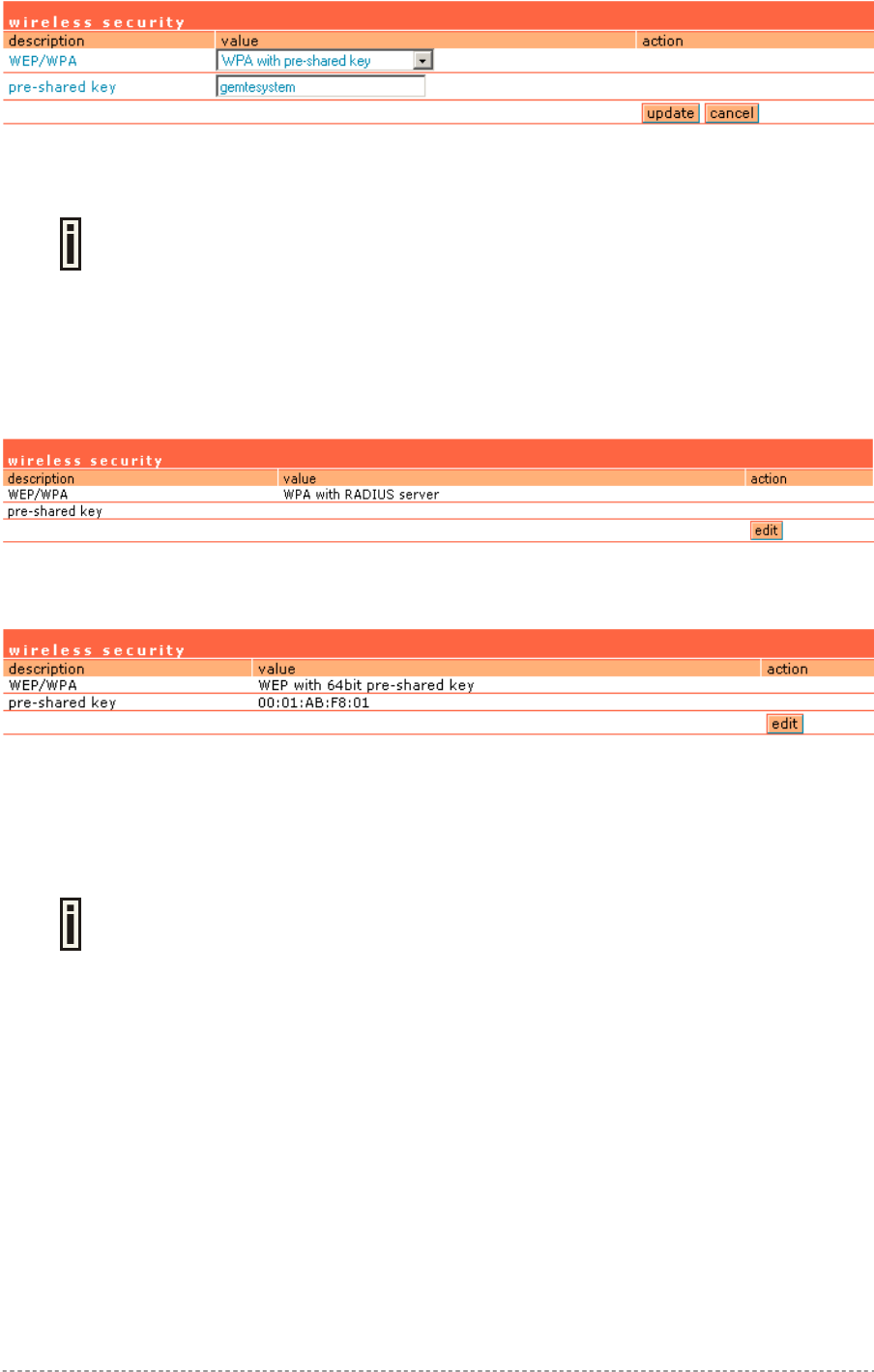
User’s Guide Chapter 7 – Reference Manual
Figure 88 – WPA with Pre-shared Key Security Settings
Pre-shared Key – specify the pre-shared key for WPA security [8-64 characters].
The encryption pre-shared key must also be entered into the WLAN card
configuration of the mobile clients.
Update – click the button to apply security setting to your wireless network.
WPA with RADIUS server makes use of external AAA (RADIUS) server to generate and exchange
dynamic WPA keys between P-560 and user station. To configure the WPA with RADIUS server
security on the P-560 use the network interface | wireless | security menu and select the WPA with
RADIUS server security method:
Figure 89 – WPA with RADIUS Server Security Settings
To configure the WEP encryption, select the WEP key algorithm and enter the pre-shared key:
Figure 90 – WEP Security Settings
WEP keys are entered as a series of colon-separated HEX (0-9, A-F, and a-f) pairs:
5 pairs for 64-bit (e.g. 00:AC:01:35:FF)
13 pairs for 128-bit (e.g. 00:11:22:33:44:55:66:77:88:99:AA:BB:CC)
The encryption pre-shared key must also be entered into the WLAN card
configuration of the mobile clients.
Network Interface | Wireless | ACL
Use the ACL service to control the default access to the wireless interface (eth0) of the AC or define
special access rules for mobile clients. Configure the ACL using the network interface | wireless | ACL
menu:
Gemtek Systems Page 78
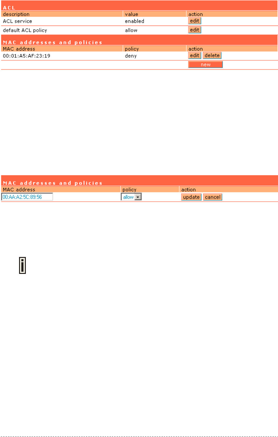
User’s Guide Chapter 7 – Reference Manual
Figure 91 – ACL Service
ACL service – click the edit button to enable or disable the access control service on device. By
default the ACL service is disabled and all mobile clients connections to the AC are allowed (no ACL
rules are applied to the mobile clients).
Default ACL policy – click the edit button to change the default ACL policy [allow/deny]. Select allow
to allow all mobile clients to access this access point or deny to prevent all mobile clients from
accessing your access point. Clients may also be subject to rules in the MAC addresses and
policies table.
You can create your own access list if you need to define special access rules for specific network
devices. The access control list is based on the network device's MAC address. In the MAC
addresses and policies table, you need only specify the network device MAC address and its
access policy (accept/deny) with the new rule. Click the new button to define the ACL rule:
Figure 92 – Add ACL Rule
MAC Address – enter the physical address of the network device you need to (MAC address) The
format is a list of colon separated hexadecimal numbers (for example: 00:AA:A2:5C:89:56).
Policy – select the permission of the rule to determine whether the specified network device should
be allowed or denied as an access point client [allow/deny].
The special ACL rule policy should differ from the default ACL policy otherwise the
ACL rule does not work.
Update – click the button to add new ACL rule.
Gemtek Systems Page 79
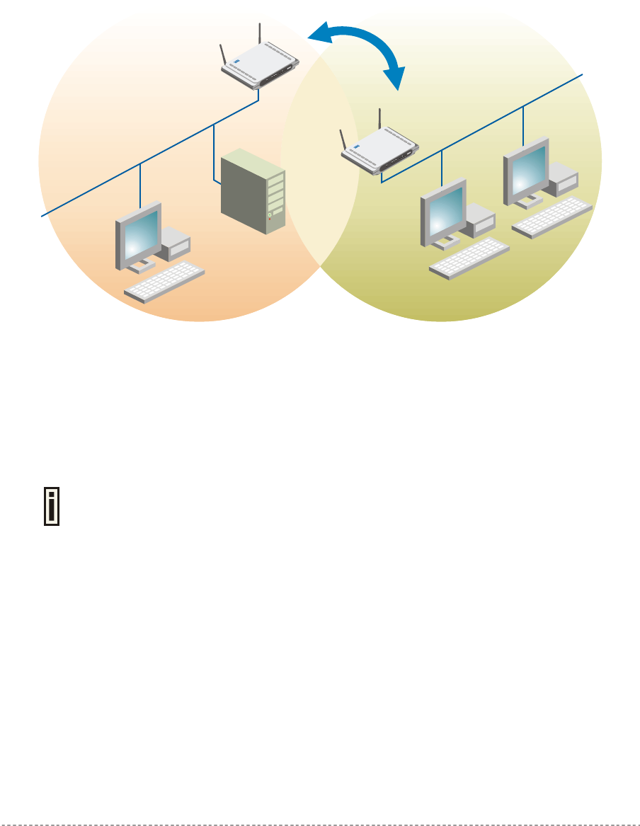
User’s Guide Chapter 7 – Reference Manual
Network Interface | Wireless | WDS
A WDS (Wireless Distribution System) allows you to create a wireless network infrastructure.
Normally, the access points must be connected with a wire (LAN), which is generally an Ethernet
connection in business applications. Once connected, these access points create wireless cells
allowing a wireless connection. The WDS feature allows the access points to be wirelessly connected
to another access point, eliminating the need to the wired connection between them:
WDS Link
Wired LAN
P-560
Wired LAN
P-560
Figure 93 – WDS Link
The WDS mode is configured by entering the WDS link peer access points (AP e.g. P-560) MAC
address in each other’s AP configuration e.g. Web interface. As a result APs that relay data received
from a wireless station to another access points (and vice versa) have to receive and send each
packet over the same channel. Hence the overall throughput will be reduced for each relay link.
The radio channel in all WDS link peer APs must be the same.
To configure the WDS links use the network interface | wireless | WDS menu, click the edit button
and enter the peer access point MAC addresses:
Gemtek Systems Page 80

User’s Guide Chapter 7 – Reference Manual
Figure 94 – Add WDS Link
MAC for Per AP [1-8] – enter wireless interface (eth0) MAC address of the peer AP for the WDS
link [6-HEX pairs separated by colon [1-9] [A-F] [a-f]].
You can discover the wireless interface (eth0) MAC address of your P-560 in the
system | status page.
Update – click the button to update you system with WDS links.
Gemtek Systems Page 81
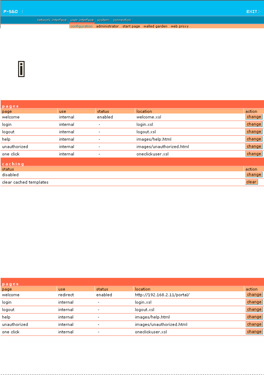
User’s Guide Chapter 7 – Reference Manual
User Interface
Use the user interface menu to configure device settings affecting the user interface. If you need to
configure the: welcome/login/logout/help/unauthorized pages, administrator settings, start page or
free sites, use the user interface menu.
Figure 95 – User Interface Menu
User Interface | Configuration | Pages
Detailed description about user page customization is given in the Chapter 4 –
User Pages.
The welcome/login/logout/help pages can be easily changed to user defined pages by choosing the
configuration menu. The pages configuration menu is displayed by default:
Figure 96 – Available User Pages for Configuration
Login/Logout/Help/Unauthorized pages settings detailed description is given in the Chapter 4. Only
Welcome page settings reference is provided here.
Welcome – first page the user gets when he/she opens its browser and enters the URL.
Internal – choose this option when using the internal user pages templates.
External – choose this option when uploading your own user pages templates.
Redirect – choose this option when using the Extended UAM function (see Chapter 4,
section: Extended UAM).
Status – choose enable/disable welcome page status. Note that redirect option with status ‘disabled’
would work.
Location – enter location for external templates or redirect (e.g. WAS IP address).
Figure 97 – Redirect User Pages
Gemtek Systems Page 82
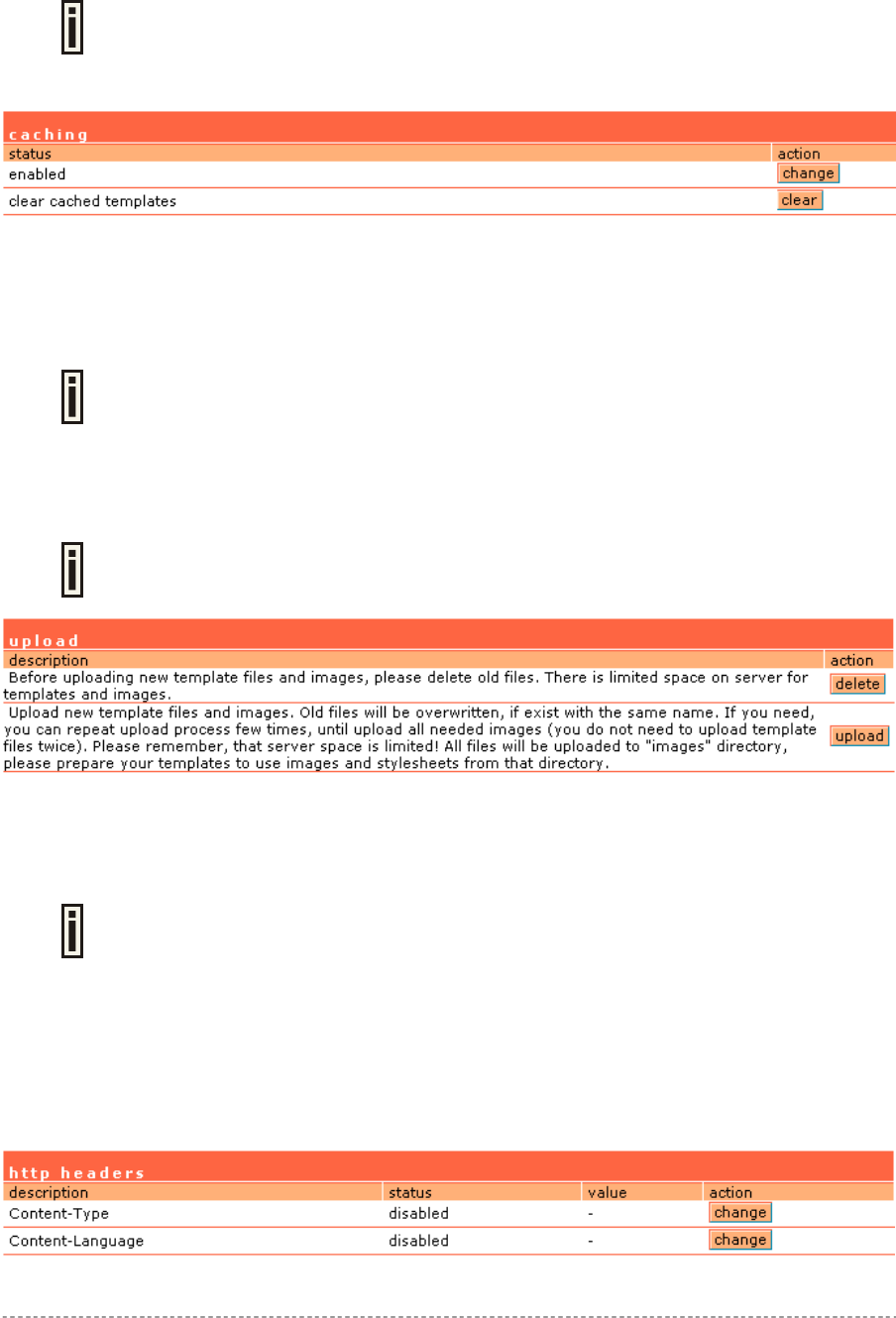
User’s Guide Chapter 7 – Reference Manual
Welcome page with redirect option selected redirects the user authentication process to the
specified location. The user welcome/login/logout page can be implemented as simple HTML (not
required to use the .XSL or default user pages templates) in such case.
The redirect location URL should be specified as Walled Garden URL, otherwise
the redirect would NOT WORK.
Figure 98 – Caching Option
Caching option can be used for caching the external uploaded user pages (available choice:
enabled/disabled)
Clear – click the button to clear cached user pages.
Controller cache is also cleared after device reboot/reset.
User Interface | Configuration | Upload
Look for the user pages template samples in the Installation CD delivered to you
with the product.
Figure 99 – Upload Page
Delete – click the button to delete earlier uploaded files from Hotspot-in-a-Box memory.
Upload – click the button to select and upload new user pages.
How to upload user pages see in the Chapter 4 – User Pages.
User Interface | Configuration | Headers
System administrator can set HTML headers encoding and language settings for AC web
management interface and new uploaded user pages. Select user interface | configuration |
headers menu:
Figure 100 – HTTP Headers Settings
Gemtek Systems Page 83
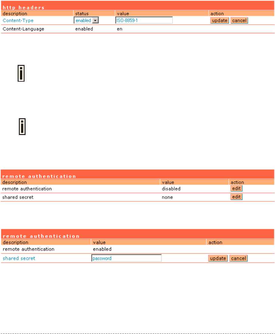
User’s Guide Chapter 7 – Reference Manual
P560 device supports some http META tags. Syntax of such META tags:
<META HTTP-EQUIV="name" CONTENT="content">
Currently P560 supports Content-Type and Content-Language tags:
Content-Type is used to define document char set (used, when text has non-Latin letters, like
language letters).
Content-Language may be used to declare the natural language of the document.
P560 automatically adds defined content-type and content-language to generated XML. Then user
pages (.XSL) templates will use these parameters to generate the output HTML.
Click the change button to define new headers of the web management interface on user pages
templates. The default HTML encoding is ISO-8859-1, language = English. Enable the HTTP header
status and default values appear:
Figure 101 – Set HTTP Headers
The system administrator can set his own header encoding and language settings.
Use the HTML 4.01 specification to define the header encoding and language.
User Interface | Configuration | Remote Authentication
Read more about extensions feature in Chapter 4, section: Extended UAM.
The Remote Authentication feature under the user interface | configuration menu allows an
external Web Application Server (WAS) to intercept/take part in the user authentication process,
externally log on and log off the user as necessary. It provides means to query user session
information as well. By default such remote authentication is disabled:
Figure 102 – Remote Authentication
Click the edit button next to appropriate settings to specify remote authentication parameters:
Figure 103 – Enable Remote Authentication
Remote Authentication – select status: [enabled/disabled].
Shared Secret – enter password for WAS to communicate with AC [sting (4-32), no spaces allowed].
Gemtek Systems Page 84

User’s Guide Chapter 7 – Reference Manual
User Interface | Configuration | One-Click Roaming
One-Click roaming is the ability of T-mobile customers to use the T-mobile Hotspot service in Third
Part Hotspots, while the authentication and billing is entirely realized through T-mobile. The Third Part
Hotspot only provides the access to the T-mobile WLAN platform. Use the network interface |
configuration | one click menu to configure this feature. By default One-Click roaming is disabled.
Click the edit button to change roaming status.
Figure 104 – One-click Roaming Settings
To add a new One-Click partner, click the new button:
Figure 105 – Add new One-Click partner
Name – enter One-Click roaming partner’s name.
Status – select status: [enabled/disabled].
Username – enter username that is valid user name on RADIUS server [text string, can not be
empty].
Password – enter password by which user should be authenticated [text string, can not be empty].
Portal URL – enter T-mobile portal URL to redirect user when One-Click roaming is enabled (optional
parameter).
Type – choose source routing policy: clients’ traffic can be either routed directly via secondary router
or via PPTP tunnel. Choose gateway to route clients’ traffic via specified router’s IP address. Or
choose PPTP- [name] tunnel that was created for t-mobile users’ traffic to route through.
IP address – enter One-Click roaming gateway IP address that is reachable via WAN interface [can
not be empty if gateway type is selected].
Update – click to update One-Click roaming settings.
Welcome Pages are stored on Portal. Every user, even T-mobile and Netcheckin
will see Welcome pages loaded from Portal server. The Welcome page with portal
URL should be entered on network interface | configuration | page.
See the following diagram to understand One-Click roaming:
Gemtek Systems Page 85
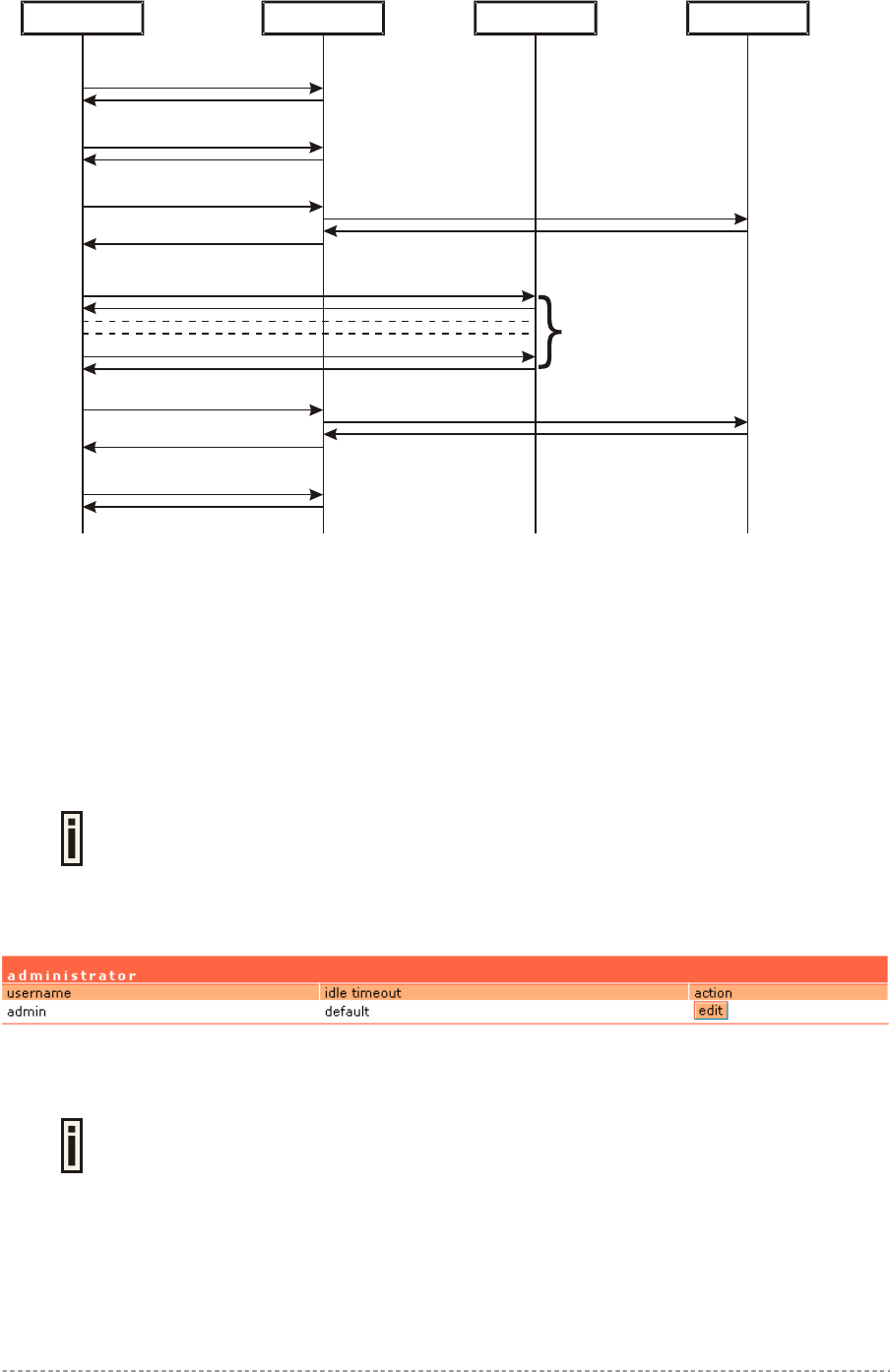
User’s Guide Chapter 7 – Reference Manual
Client AC RADIUS Server
Welcome page is loaded
Select T-Mobile
Login use
r
Open popup
Enable source routing
Authentication
Logout use
r
Cancel source routing
Redirect routing to Welcome page
Welcome page
Open window / redirect to T-Mobile portal
T-Mobile Portal
Logout use
r
Figure 106 – One-Click Roaming diagram
When T-mobile user attempt connect to internet it is redirected to ‘Welcome Page’ on access
controller. Then client selects T-mobile, AC internally authenticates client with a provided username
and password. AC opens a new browser window and which in turns open popup window. Latter
popup window will allow canceling source routing policy at any time and returning to a welcome page.
User Interface | Administrator
The system administrator also can be the RADIUS user with corresponding
attributes.
The administrator menu is for changing the administrator’s settings: user name and password:
Figure 107 – Administrators Settings
Default administrator logon settings are:
User Name: admin
Password: admin01
Gemtek Systems Page 86
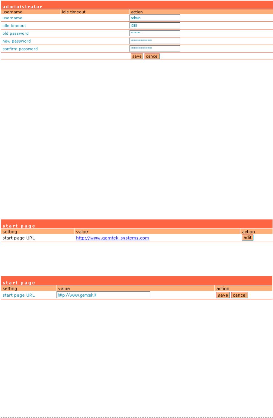
User’s Guide Chapter 7 – Reference Manual
To edit or change the administrator settings simply click the edit button:
Figure 108 – Change Administrator Settings
Username – administrator username for access to Access Controller (e.g. web interface, CLI mode)
[1-32 symbols, spaces not allowed].
Idle Timeout – amount of administrator inactivity time, before automatically disconnecting
administrator from the web interface [300-3600 seconds]. The default idle time: 10minutes (600
seconds).
Old Password – old password value.
New Password –new password value used for user authentication in the system [4-32 symbols,
spaces not allowed].
Confirm Password – re-enter the new password to verify its accuracy.
Save – click to save new administrator settings.
User Interface | Start Page
The start page is the default web page where users will be redirected after log-on. This value will be
overwritten by the WISP RADIUS attribute no.4 "Redirection-URL" if provided in the authentication
response message. Use the user interface | start page menu to view or change the start page URL:
Figure 109 – Start Page
The administrator can change the start page by clicking the edit button. The value entry field will
change into an editable field:
Figure 110 – Edit Start Page
Value – enter new redirection URL of start page in valid format [http://www.startpageurl.com].
Save – to save new settings.
Cancel – restores all previous values.
User Interface | Walled Garden
The walled garden is an environment that controls the user's access to Web content and services.
This feature gives the ability to define a free, restricted service set for a user not yet logged into the
system. Use the user interface | walled garden menu to view or change the free URLs or hosts:
Gemtek Systems Page 87
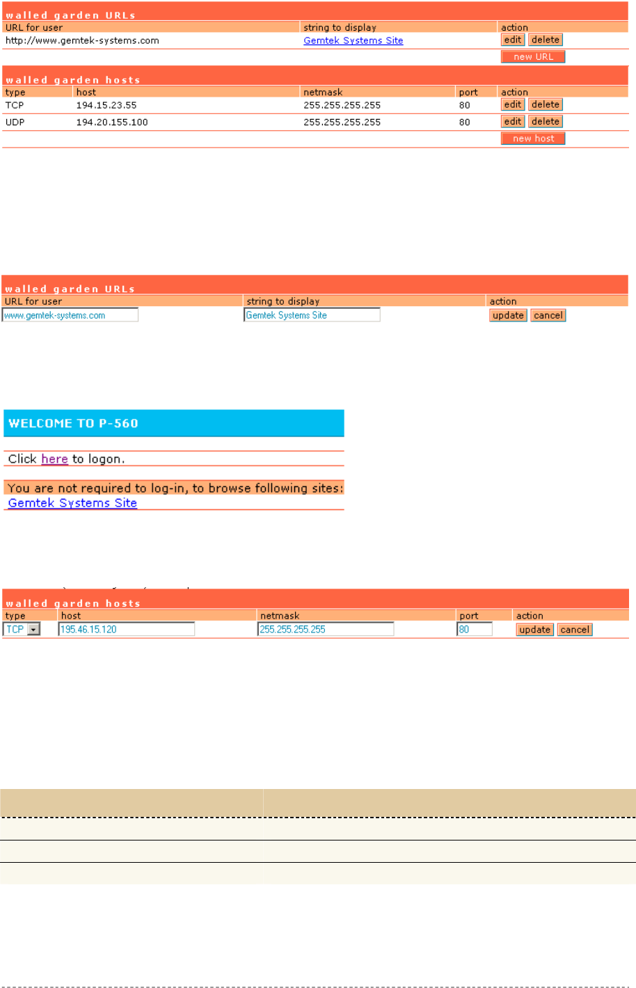
User’s Guide Chapter 7 – Reference Manual
Figure 111 – Walled Garden
Edit – edit the selected URL or host. All settings become available for editing.
New URL – click the new URL button and enter the new URL and its description. Save entered
information by clicking the update button:
URL for User – define full URL address [www.gemtek-systems.com].
String to Display – site description visible to user as link on the welcome and login page:
Figure 113 – Walled Garden link in the Welcome Page
New Host – If you need to define hosts (web servers) for walled garden, specify hosts by clicking the
new host button and click the update button:
Figure 114 – Walled Garden Host
Type –select the data traffic protocol for host server [TCP/UDP].
Netmask – enter the network mask to specify the host servers network.
Port – network port, which is used to reach the host [1-65535]. For standard protocols use the default
ports:
Port
Delete – delete the selected URL or host.
Figure 112 – Add New URL part 1
Host – Web server address [IP address or host name].
Protocol
HTTP 80
HTTPS 443
FTP 21
Gemtek Systems Page 88
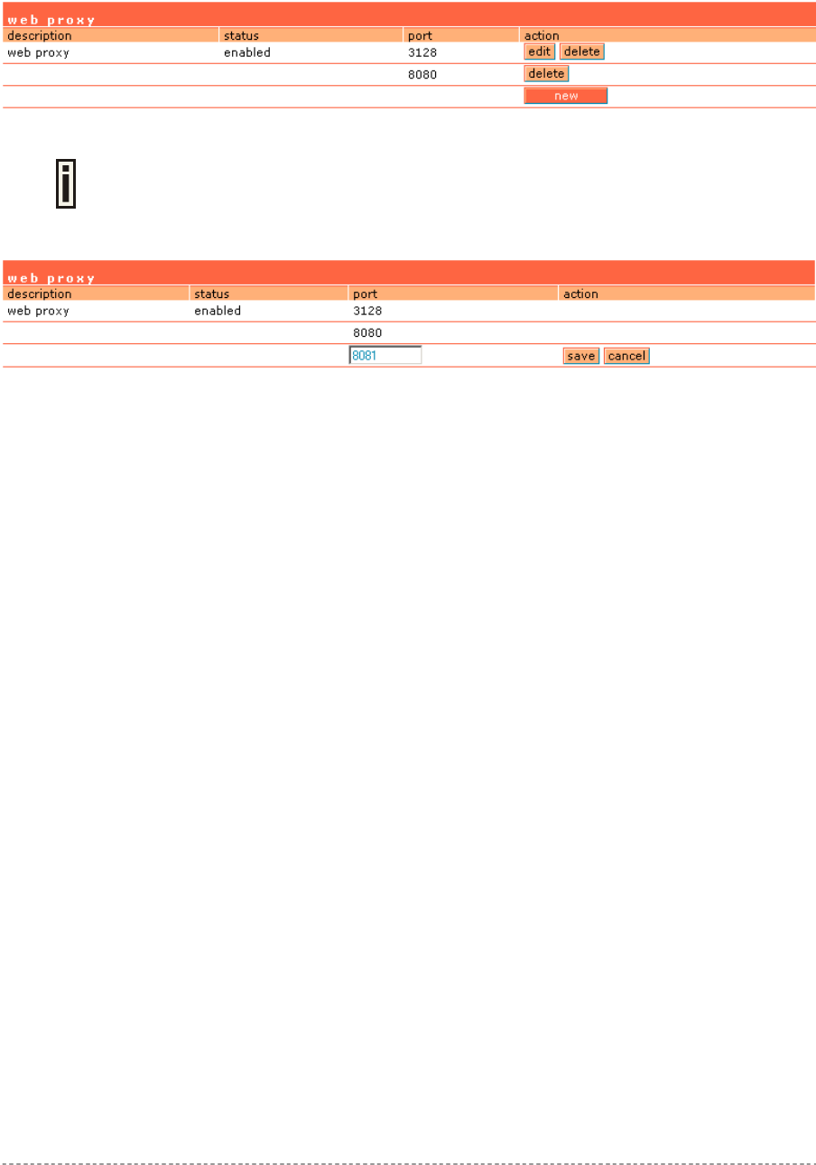
User’s Guide Chapter 7 – Reference Manual
User Interface | Web Proxy
The enabled web proxy allows any clients’ connections with configured proxy settings on their
browsers. The AC accepts any client proxy configurations and grants the access to the Internet. The
system administrator should list only ports the AC is listening on for proxy requests.
Figure 115 – Web Proxy
Web proxy is enabled by default and the port numbers are: 3128 and 8080.
To add more port number for web proxy, click the new button:
Figure 116 – Add Web Proxy Port
Port – add port number for web proxy to listen to [1-65535].
Save – click the button to save new proxy port number.
Gemtek Systems Page 89
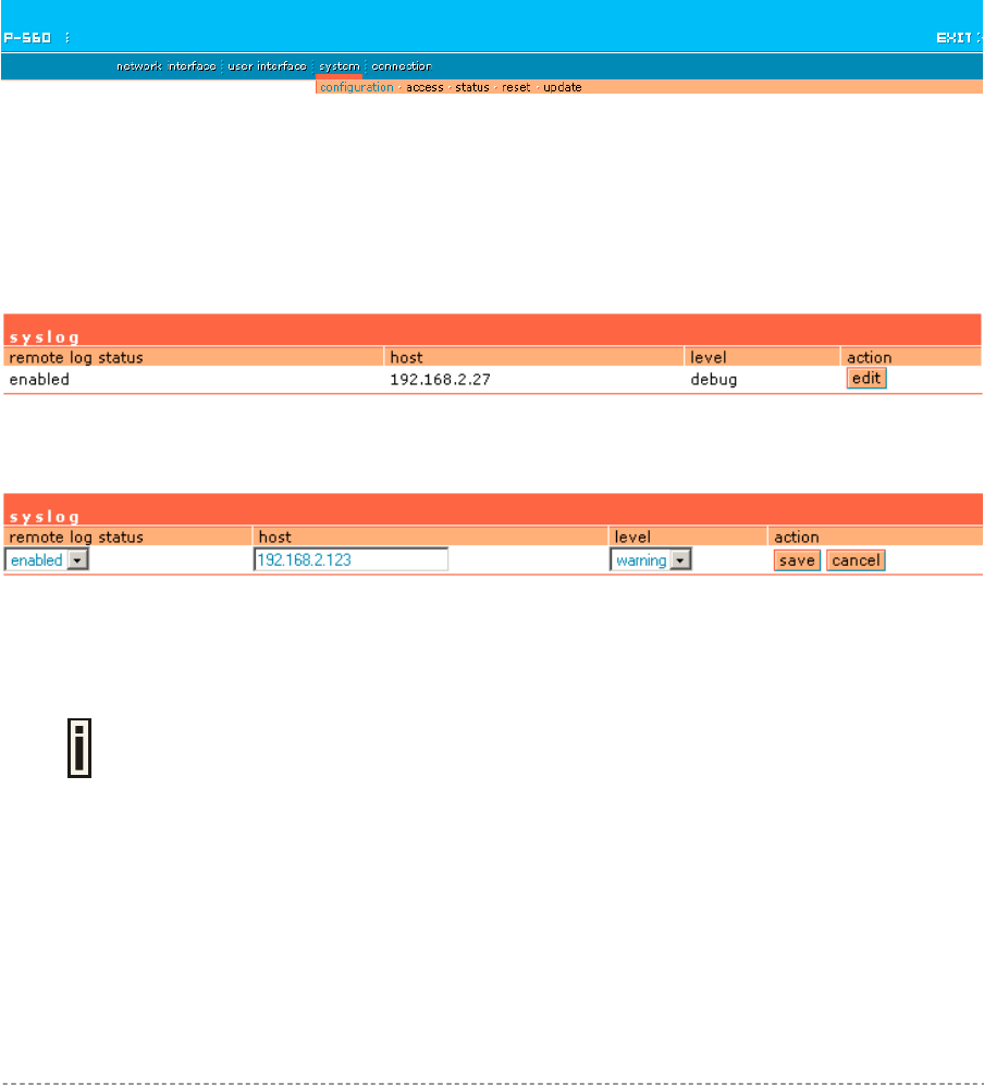
User’s Guide Chapter 7 – Reference Manual
System
Use the system menu to configure such system utilities:
Syslog – for sending system and debug messages via the syslog protocol.
Trace system – trace such controller services as PPTP and PPPoE.
Clock – manual setting of internal device clock.
NTP – set the Network Time Protocol service on the AC.
Certificates – upload your own SSL certificate and private key files for server.
Save and Restore – save current AC configuration and restore.
Use the system menu to define default access/visitor access to the device via or using:
Telnet – enable telnet connections to AC.
AAA – enable different AAA methods.
UAT – enable the service.
SNMP – enable/configure SNMP management.
Use the system menu to check the system status, reset the device, or update with new firmware.
Figure 117 – System Menu
System | Configuration | Syslog
You can trace your AC system processes and get the system log messages remotely using the
system | configuration | syslog menu (by default the syslog utility is disabled):
Figure 118 – Syslog Settings
To enable the syslog remote sending function, click the edit button and choose the enabled option:
Figure 119 – Configure Syslog Messages
Remote Log Status – choose disable/enable remote log [enabled/disabled].
Host – specify the host IP address where to send the syslog messages [host IP address].
Be sure the remote host is configured properly to receive the syslog protocol
messages.
Level – select the messages level you need to trace. The level determines the importance of the
message. The levels are, in order of increasing importance:
Debug – debug messages including more important level messages: [info/warning/error/fatal].
Informational – informational messages including [warning/error/fatal]
Warning – warning condition messages including [error/fatal]
Error – error and critical condition messages including [fatal]
Fatal – critical and fatal condition for device messages. Actions should be taken immediately.
Gemtek Systems Page 90
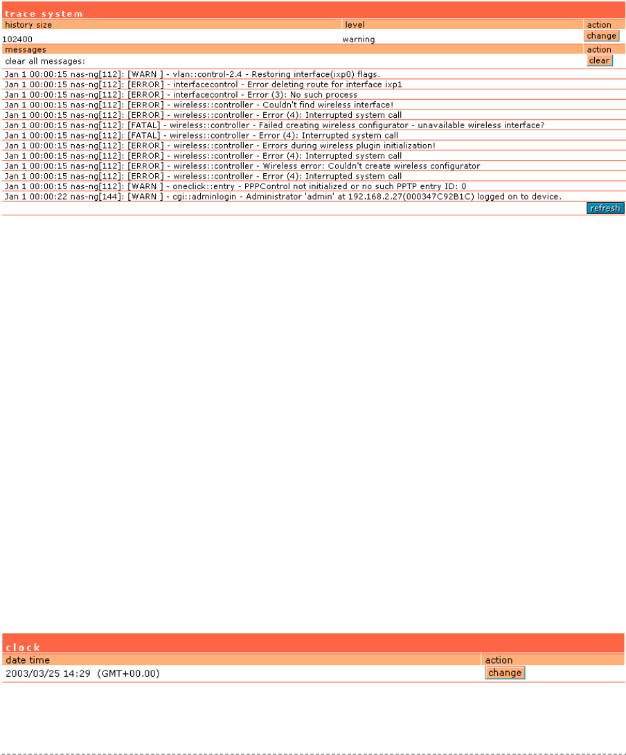
User’s Guide Chapter 7 – Reference Manual
Save – save changes. The syslog messages will be started to send to the specified host.
Cancel – restore the previous values.
System | Configuration | Trace System
The trace system utility debugs system services and protocols if malfunction occur. Trace system
works with started services as DHCP, PPTP, PPPoE, telnet and SNMP and shows number of system
messages according to the selected history size. The trace system can help operators to locate mis-
configurations and system errors. Select system | configuration | trace system menu to view
current syslog messages in case of troubleshooting of one of the services:
Figure 120 – Trace System
By default, trace system utility is switched on. The latest messages are displayed at the end of the
message list.
History Size – select the message history size to display [102400-512000 bytes].
Level – select the messages level you need to trace. The level determines the importance of the
message. The levels are, in order of increasing importance:
Debug – debug messages including more important level messages: [info/warning/error/fatal].
Informational – informational messages including [warning/error/fatal]
Warning – warning condition messages including [error/fatal]
Error – error and critical condition messages including [fatal]
Fatal – critical and fatal condition for device messages. Actions should be taken immediately.
Change – click the change button to apply new history size or selected message level. Trace system
will start to sort by selected level at once you click the change button.
Clear – delete all displayed messages.
Refresh – click to refresh trace system messages.
System | Configuration | Clock
To set the Hotspot-in-a-Box internal clock, use the clock utility, accessed by selecting the system |
configuration | clock menu link:
Figure 121 – Clock Utility
Gemtek Systems Page 91
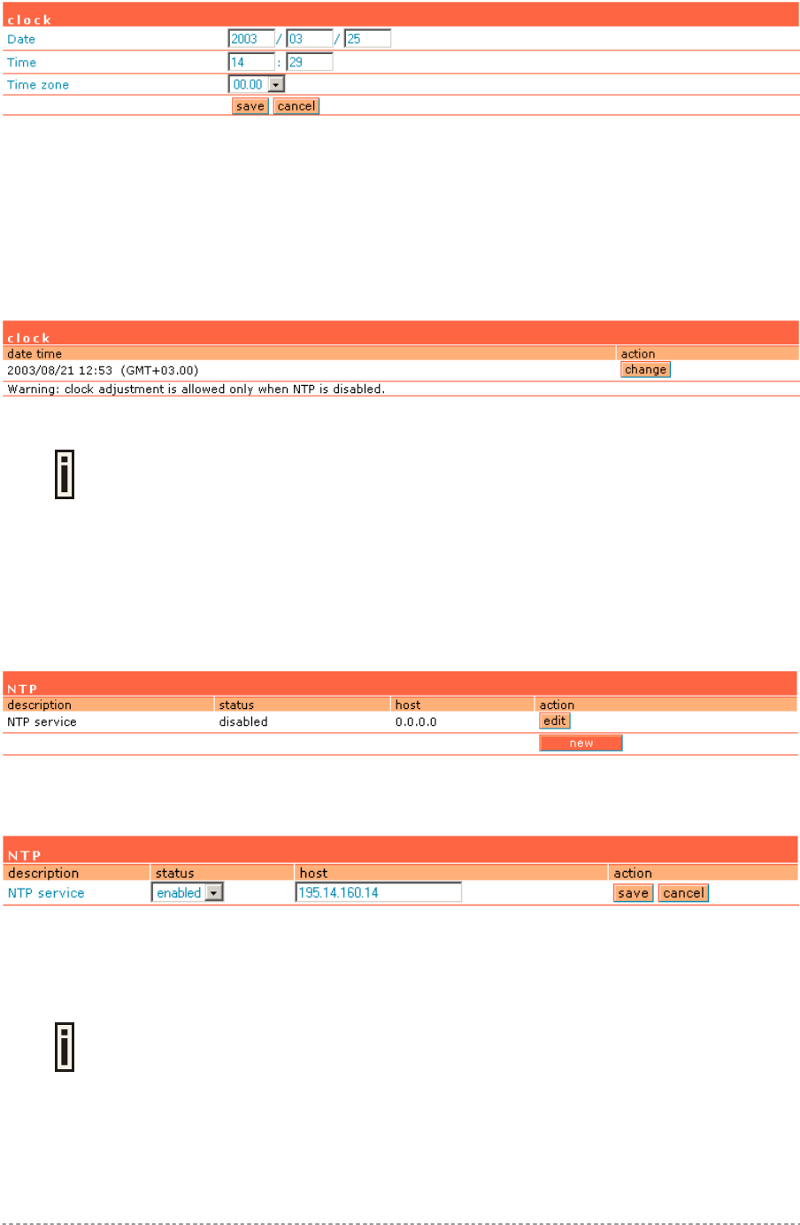
User’s Guide Chapter 7 – Reference Manual
To adjust the clock settings, click the change button:
Figure 122 – Set Clock Settings
Date – specify new date value [year/month/day].
Time – specify time [hours: minutes].
Time Zone – select the time zone [-12.00 – 14.00]. If the NTP service is enabled the selected time
zone will be applied to the clock settings also.
If the NTP server (see the next section for reference) is enabled on the system, no manual clock
setting is available except time zone.
Figure 123 – Clock and NTP
Only time zone change is available when NTP server is used.
System | Configuration | NTP
The NTP (Network Time Protocol) is used to synchronize the clock of the AC to a selected time
reference. You can synchronize the system clock settings using the system | configuration | NTP
menu:
Figure 124 – NTP Service
By default NTP service is disabled. To start the service, click the edit button:
Figure 125 – Enable NTP
Status – select appropriate status for NTP service [enabled/disabled].
Host – specify the trusted NTP server IP on the field. It works only with enabled NTP function.
The NTP synchronize the device clock with GMT + 0 time. If you need to set the
time zone, use the system | configuration | clock menu.
You may want to add more than one NTP host, for example, in the case where the first host fails to
connect. Click the new button to add additional host settings:
Gemtek Systems Page 92
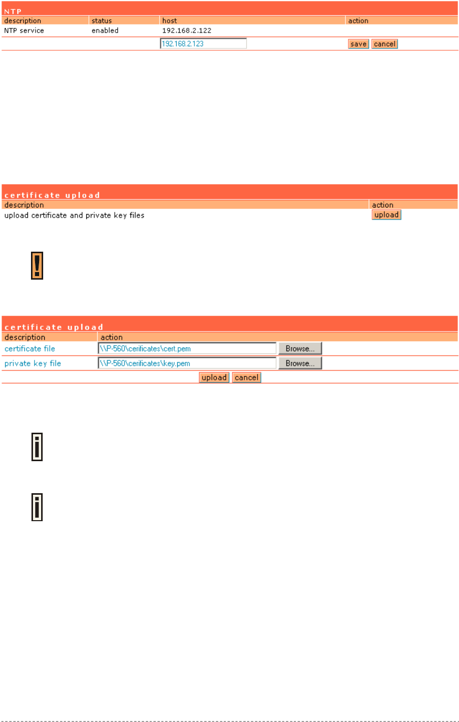
User’s Guide Chapter 7 – Reference Manual
Figure 126 – Add New NTP Host
Host – add additional NTP service hosts [1-128]. This NTP server will be used, if connection to the
first defined NTP server is lost.
System | Configuration | Certificate
You can upload your own SSL certificates files for HTTP connection using the certificate menu under
the system | configuration menu:
Figure 127 – Certificate Upload
Only these certificate files are accepted:
Server PEM-encoded X.509 certificate file
Server PEM-encoded private key file
Click the upload to upload your own SSL certificates and private key files:
Figure 128 – Upload New Certificate
Certificate File – the PEM-encoded certificate file for the server.
Corresponding RSA or DSA private keys SHOULD NOT be included.
Private Key File – the PEM-encoded private key file for the server.
Private key SHOULD NOT be encrypted with a password. This private key should
correspond to the certificate above.
Upload – upload new certificates.
Depending on the public key infrastructure implementation, the certificate includes the owner's public
key, the expiration date of the certificate, the owner's name, and other information about the public
key owner. The default certificate implemented in the AC includes the following:
Gemtek Systems Page 93
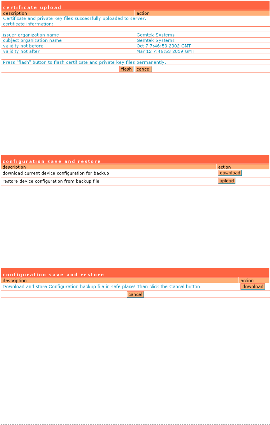
User’s Guide Chapter 7 – Reference Manual
Figure 129 – Default Certificate Properties
Flash – upload new certificates into the controller.
Cancel – cancel new certificate upload.
System | Configuration | Save and Restore
You can save your current device configuration file locally using the save and restore menu under
the system | configuration menu:
Figure 130 – Save and Restore
Such device configuration is saved in the specific format file (.cfg):
Network configuration settings (including network interface, VLAN, port forwarding, route,
management subnet, DHCP, DNS, RADIUS, tunnels)
User interfaces configuration settings (including user pages templates)
System configuration settings (including syslog, NTP configuration, access settings)
Connection settings (including e-mail redirection and station supervision)
Click the download button to start saving the configuration file. You can change or leave the default
configuration file description:
Figure 131 – Edit Configuration File Description
Download – click the download once again to save the configuration file under the selected path in
your computer. Now the last saved configuration is successfully stored in your local computer.
Cancel – click the cancel button to back to main configuration page.
You can use this file any time you want to restore this configuration to the device by using the upload
button (see: Figure 130 – Save and Restore). Select the configuration file and upload it on the device:
Gemtek Systems Page 94
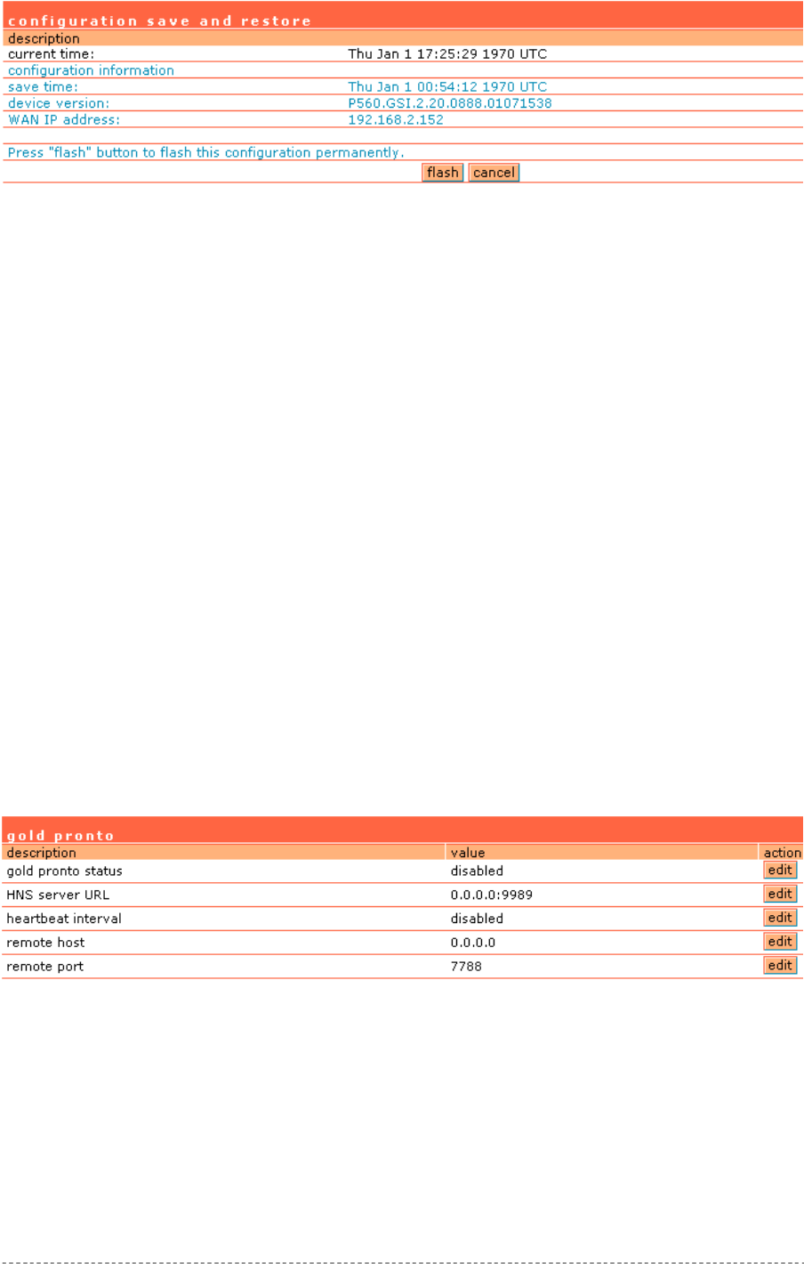
User’s Guide Chapter 7 – Reference Manual
Figure 132 – Upload Configuration File
Flash – click the button to apply configuration setting to the device.
System | Configuration | Pronto
The goal of the pronto-compatible agent program is to ensure that a partner’s hotspot is interoperable
with Pronto’s Hotspot OSS. Pronto compatibility agent is used to download and overwrite current
configuration (only some parameters which are listed below) from pronto server using WEB proxy. On
device boot only these parameters will be overwritten:
LAN IP.
WLAN (wireless LAN) IP.
LAN DHCP range, DHCP default lease time, max lease time.
WLAN DHCP range, DHCP default lease time, max lease time.
WLAN channel.
WLAN SSID.
WEP key length (64-bit or 128-bit).
WEP key format (HEX).
SMTP server IP and port.
Location name.
Walled garden entries.
Default RADIUS authentication, accounting and accounting backup servers IP.
Default RADIUS authentication, accounting and accounting backup shared secrets.
SNMP Read-Only and Read-Write communities.
SNMP traps host. There will be created 3 traps with different trap types (v1, v2, inform) on the
same host.
By default Pronto feature is disabled:
Figure 133 – Default Pronto Settings
Gold pronto status – select pronto compatibility agent status [enable/disable].
HNS server URL – specify HNS server URL.
Heartbeat interval – specify interval between heartbeat messages in seconds: 1-4 numbers [0-3600],
no spaces allowed. ‘0’ means that heartbeat is disabled. No heartbeat value specified - system will
use external server value. Heartbeat messages are sending between the nodes that indicate a node
is up and running.
Remote host – specify remote host [IP address or host name].
Remote port – specify remote host port number: 1-5 numbers, no spaces allowed, [1-65535].
Gemtek Systems Page 95
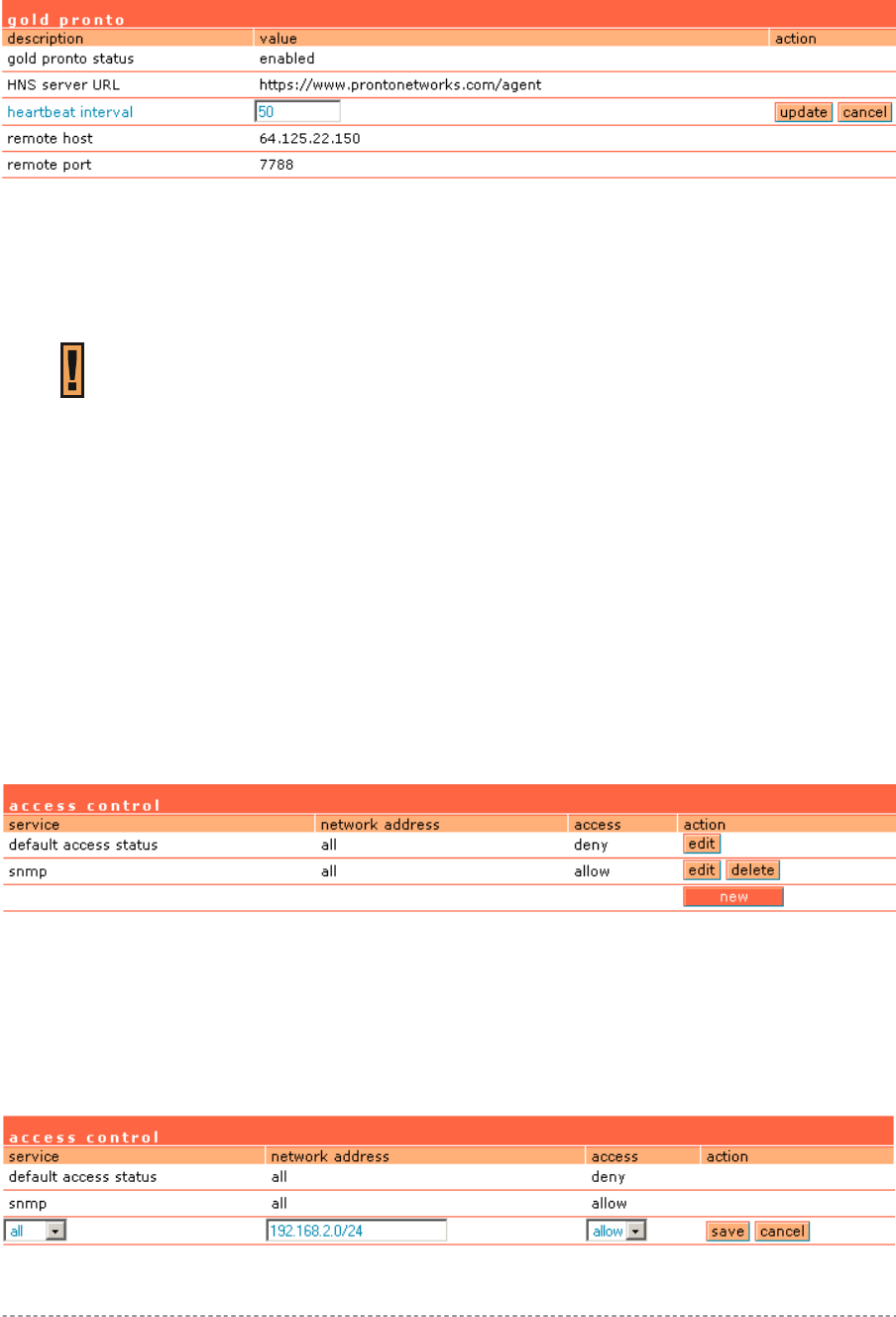
User’s Guide Chapter 7 – Reference Manual
Edit – click to edit required parameter.
Change Pronto status to enable and configure the rest Pronto settings. To configure Pronto settings,
click the edit button next to appropriate parameter and specify value. Reboot the device.
Figure 134 – Configure Pronto Settings
Update – click the button to apply pronto agent settings.
Cancel – restore the previous value.
After reboot device’s configuration will be changed automatically.
Note that if Pronto agent is enabled, after reboot existing configuration will be
overwritten with Pronto server parameters’ values.
System | Access | Access Control
Use the access control menu to control the access management to your AC and to specific services.
Access control to your device includes access to these services:
Telnet
SSH
SNMP
Thus, the administrator can control the access of a single or every user to the controller via telnet,
SSH or SNMP. This can be done by creating the access control list in the AC and checking the
incoming user’s IP address.
Default access status is used to deny all connections except the SNMP service to the controller.
SNMP service is used to access your device via the KickStart utility.
Figure 135 – Access Control
Edit – click to edit the default access status [allow/deny].
New – click to create new access control rule for specific network to specific service(s) [all/
/ssh/telnet/snmp].
To configure the access control, click the edit button and specify the network address and select
services to allow/deny:
Figure 136 –Modify Access Control
Gemtek Systems Page 96
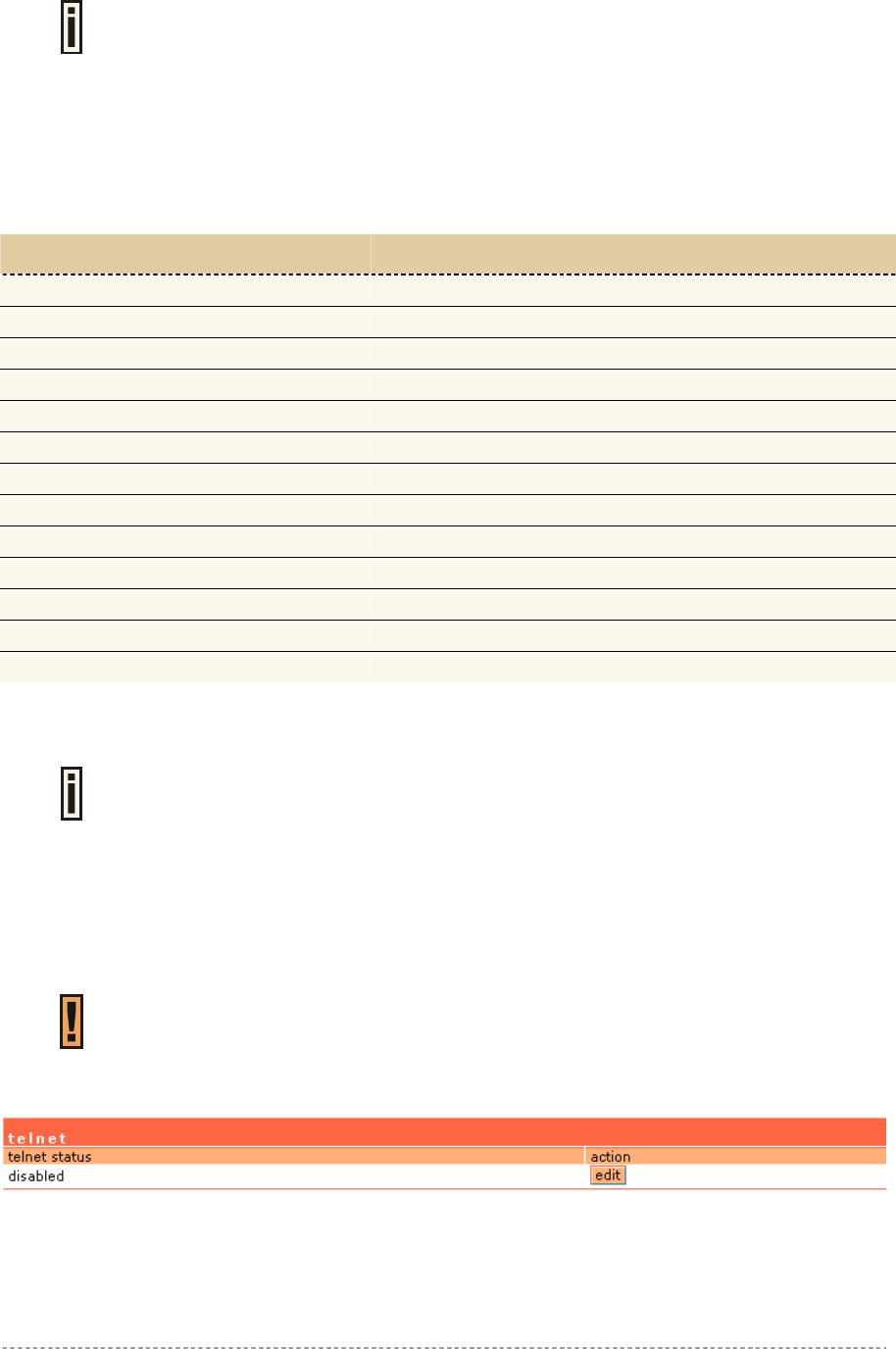
User’s Guide Chapter 7 – Reference Manual
Service – select services that access you need to control [all/ssh/telnet/snmp].
Telnet service should be also enabled in the system | access | telnet to allow the
telnet access to the controller. Otherwise, the client or network will not get telnet
access.
Network Address – specify the network or host address with netmask in bit format separated by
dash.
The /N stands for the number of bits that are in the network address. There are 32 bits, so we have
32-N bits left that are part of the network. The first N bits of x.x.x.x correspond to x.0.0.0 when N=8,
our network address, and the netmask is 255.0.0.0 (when N=8).
bits netmask
/32 255.255.255.255
/31 255.255.255.252
/30 255.255.255.248
… …
/26 255.255.255.192
/25 255.255.255.128
/24 255.255.255.0
… …
/16 255.255.0.0
… …
/8 255.0.0.0
… …
/0 0.0.0.0
Access – select the access policy: [allow/deny].
Up to 255 different access control rules can be set.
System | Access | Telnet
When the telnet function is switched on, telnet connection to the Hotspot-in-a-Box is enabled and the
administrator can connect to the CLI interface via telnet.
Make sure that default access status to the administrator PC appears as ‘allow’
under the system | access | access control menu. Otherwise, you will not be able
to connect via telnet, even though the telnet function is enabled.
By default telnet is disabled:
Figure 137 – Default Telnet Status
To switch the telnet function on, click the edit button and change the status:
Gemtek Systems Page 97
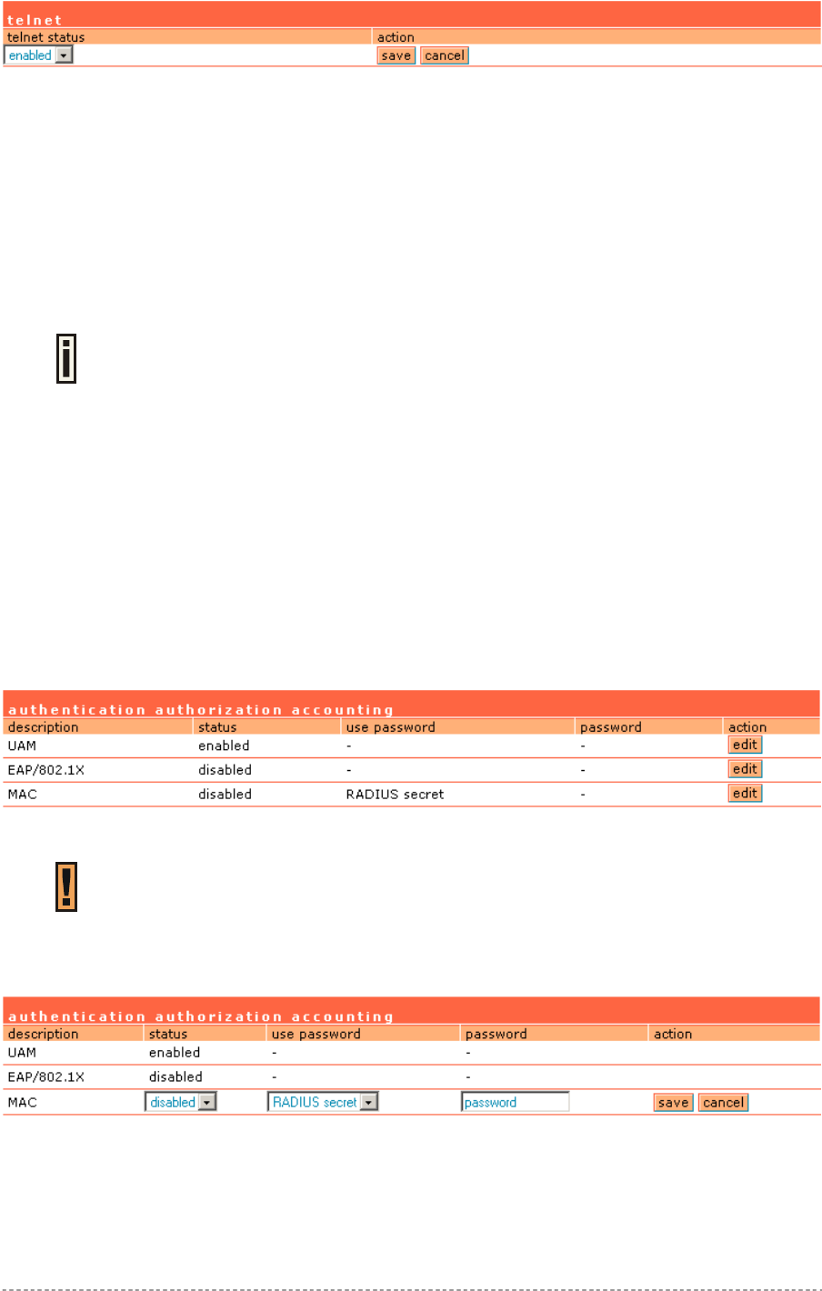
User’s Guide Chapter 7 – Reference Manual
Figure 138 – Change Telnet Status
Enabled – connection via telnet to AC is enabled.
Disabled – connection via telnet to AC is disabled.
Save – click the button to save the configuration.
Cancel – restore the previous value.
System | Access | AAA
It is recommended to use the Gemtek Systems product Smart Client Manager
(S-200) for EAP authentication methods.
Such multimode Authentication, Authorization and Accounting (AAA) methods are supported on
the AC:
UAM – Universal Access Method (web-login) method
EAP/802.1x are:
EAPMD5 – 802.1x authenticator with MD-5 method
EAPSIM – 802.1x authenticator with SIM authentication method
EAPTLS – 802.1x authenticator with TLS authentication method
EAPTTLS – 802.1x authenticator with TTLS authentication method
MAC – user is authenticated from RADIUS server by its MAC address and password.
Use the user interface | configuration | AAA menu to enable/disable appropriate authentication
method on your controller:
Figure 139 – AAA Settings
If UAM (web-login) method is disabled the subscriber will not be able to login
through the web interface.
Status – change status of selected AAA method [enabled/disabled].
For MAC authentication the following settings are required:
Figure 140 – MAC Authentication
Use Password – select [RADIUS secret] or [User defined] password for user authenticating by its
MAC address.
Password – enter password with user-defined option selected. Password will be one for all users
authenticated by MAC address [string, 4-32 characters, no spaces allowed].
Gemtek Systems Page 98
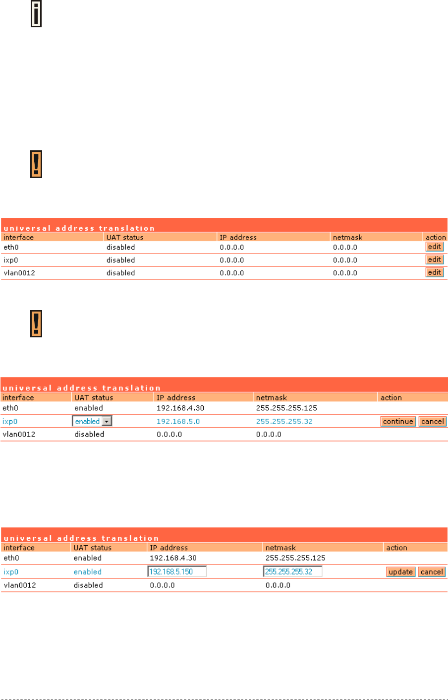
User’s Guide Chapter 7 – Reference Manual
Current RADIUS secret value is only displayed and CANNOT be changed under
the AAA menu. To change the RADIUS secret value use the network interface |
RADIUS | servers menu.
System | Access | UAT
With Universal Address Translation (UAT) enabled, the Hotspot-in-a-Box will automatically and
transparently translate fixed IP settings (IP address, gateway, DNS, proxy server) on a user’s PC so
that he can connect to the broadband Internet service. There is no need for end-users to reset their
corporate IP or web settings. Also outgoing subscriber e-mails can be redirected to the operator's e-
mail server in order to facilitate e-mail forwarding for foreign subscribers.
Universal address translation works only on LAN and VLAN interfaces with
authentication setting enabled (see more about these settings in the System |
Access | NAV).
The Universal Address Translation (UAT) function can be enabled using the system | access |
UAT menu. UAT can be configured separately for each interface. All available interfaces are listed:
Figure 141 – Universal Address Translation Settings
VLAN interface will not appear in list if it is not enabled in Network Interface |
Configuration | Interface Configuration page.
To change UAT settings on interface click the edit button in the action column. The status can be
changed now:
Figure 142 – Change Universal Address Translation Status
Interface – standard interface name on which UAT can be configured.
UAT Status –universal address translation status [enabled/disabled].
Change status or leave in the default state if no editing is necessary and click the continue button.
Then the IP address and Netmask can be changed:
Figure 143 – Change Universal Address Translation Settings
IP address – specify network IP of UAT address pool.
Netmask – specify UAT address pool network mask.
Update – update old values with entered ones.
Gemtek Systems Page 99
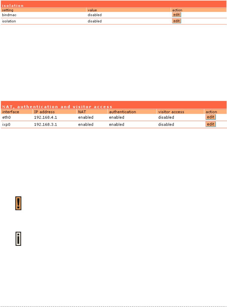
User’s Guide Chapter 7 – Reference Manual
IP address and netmask should be combined and used as pool for users on this interface. Note that
count of available IP addresses will become maximum user count on this interface - if there will be no
free IP addresses, access will be rejected because of lack of IP addresses.
System | Access | Isolation
Isolation mechanism under the system | access | isolation menu increases the security of the AC
users.
Figure 144 – Isolation
Bindmac – with bindmac function enabled, the AC binds the user’s MAC and IP addresses together
after a successful logon by the wireless client and thereby preventing Internet access to a new user
who uses the same client IP address, although be it with a different MAC address [enabled/disabled].
Isolation – enable this function to prevent users on the same LAN to communicate with each other.
Users can communicate only through the AC [enabled/disabled].
System | Access | NAV
To change visitor access on different LANs or VLANs, authentication or NAT attributes for AC
users, go to the system | access | NAV menu:
Figure 145 – NAT, Authentication and Visitor Access
Interface – interface on which the changes will be done [ixp0, non editable].
IP Address – IP address of interface [non editable].
NAT – network address translation service status [enabled/disabled]. If enabled, users can access the
Internet under its network gateway address.
Authentication – with disabled authentication, the user from his LAN gets access to the Internet
without any authentication. If enabled, authentication for Internet access is required for all users
[enabled/disabled].
This setting is important when configuring the UAT. See section: System | Access
| UAT for more details.
Visitor Access – client with specific WISPr attribute can reach the LAN with enabled visitor access
[enabled/disabled] (see more details about visitor access below).
Only one selected interface can have the visitor access enabled. Attempting to
enable an additional interface for visitor access will disable the previous interface.
Visitor Access
Users can be grouped in two logical groups: employees and visitors. By default, all users belong to
the visitors group without access to servers in the LAN. Employees have access to the Intranet
(servers that are running in the LAN), meanwhile visitors have access only to the Internet with no
way to connect and use services from servers running in the LAN. By default, clients connected on
the WLAN and LAN cannot communicate among them-selves. This is prevented by default firewall
rules. See the picture below to view the difference between employee and visitor traffic:
Gemtek Systems Page 100