GemTek Technology HR930819G Home Plug Wireless 802.11g Router User Manual
Gemtek Technology Co., Ltd. Home Plug Wireless 802.11g Router Users Manual
Users Manual
Gemtek Power Line 802.11g Wireless Router User Guide
Introduction
GT Powerline Router is a multi-function device which connects to
a cable or DSL modem providing Internet connectivity to both
wired and wireless computers. The Powerline Wireless Route
r
function lets you to securely expand the range of your local area
network, while Power utilizes the electric cord as the transfe
r
media, the 11g utilizes the electric wave.
The GT Powerline Router offers a convenient way to create a
simple network through the existing power line of a home or
office with the additional ability to provide you with access to you
r
network without wires. Offering several levels of security, the GT
Powerline Router is built with 64/128-bit WEP encryption and
802.11i (WPA /WPA-PSK, ) for the wireless pass-through and
56-bit DES encryption for the Power line pass-through There are
also some Enhanced Security Management Functions:
Wireless/Wired 802.1x, and Embedded RADIUS Server so your
data will always be secured—guaranteed.
With high data rate and power line around everywhere, you can
enjoy the high quality video or any service in any place. With a
web-based UI ( User Interface ), the GT Powerline Router is
easy to setup and maintain. All functions can be configured with
the UI via web browsers.
Important Safety Information
This product is intended for connection to the AC power. The following
precautions should be taken when using this product.
- Read all instructions before installing and operating this product.
- Follow all warnings and instructions marked on the product.
- Do not operate this product near water.
- This product relies on a building’s electrical installation for short-circuit
(over current) protection.
- Do not allow anything to rest on the product.
- The HomePlug Wireless Router should be plugged directly into an
AC wall outlet.
- Only a qualified technician should service this product. Opening or
removing covers may result in exposure to dangerous voltage points or
other risks. (Note: Opening or removing the covers will void your product
warranty).
- Unplug the HomePlug Wireless Router from the AC wall outlet and
refer the product to a qualified service representative for the following
conditions:
- If liquid has been spilled onto the product.
- If the product has been exposed to rain or water.
- If the product does not operate normally when the operating
instructions have been followed.
- If the product exhibits a distinct change in performance.
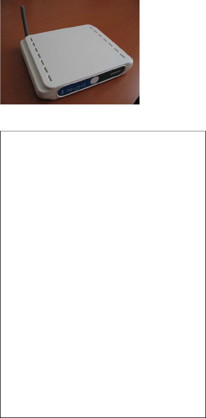
Getting start with your Powerline Device
Before installing your Powerline networking device, please examine and familiarize yourself with
it. Below is a diagram
of the GT Powerline Router along with a brief description of what each LED
and slot represent.
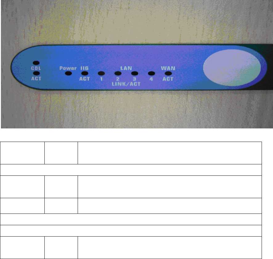
Power: Green
The Power LED illuminates when the WHRTC-100GW Homeplug
Wireless Router is powered on
For Power Line ports
Act: Green
Blinking slow when Act and blinking very fast when data is flowing
through this Power Line plug
Col: Green Blinking when collision is occurred on this port.
For WLAN
IEEE 802.11b/g
Act Green
Steady on when link is ready, blinking with the traffic through
802.11g WLAN
What This Package Contains?
Upon you receive your wireless Router, please check that
the following contents are packaged:
- HomePlug Wireless Router (GT Powerline Router)
- CD
- User's manual
- Quick Install Guide
- RJ 45
- Power cord
Necessary Equipment
- One or more computers with wireless device, and it's software already installed
- Microsoft TCP/IP networking protocol installed on each PC
- Web browser installed on each PC
Equipment that can be used with the GT Powerline Router
- Broadband modem
- GT Powerline Router Broadband router
- Additional PCs with a wireless or Powerline Device
Important: After receiving the wireless Router, please check for
any shipping damages to the carton before proceeding with any installations.
PC or Laptop Setup Guide
Note: If you have not installed your Wireless device to your laptop
So far, please do so. For instructions on how to install your
Wireless device, please contact the manufacturer of that wireless
device.
To configure the Wireless device to work with your GT Powerline Router,
please follow the following steps:
1. Plug GT Powerline Router into an outlet.
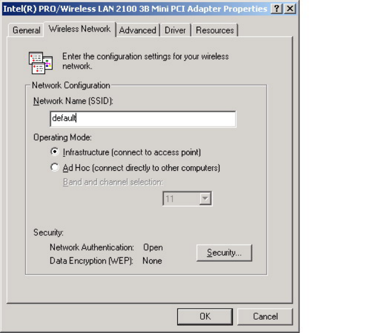
2. Go to the wireless card's configuration screen or window. It
should resemble figure 1 or others.
PC or Laptop Setup Guide
Note: If you have not installed your Wireless device to your laptop
So far, please do so. For instructions on how to install your
Wireless device, please contact the manufacturer of that wireless
device.
To configure the Wireless device to work with your GT Powerline Router,
please follow the following steps:
1. Plug GT Powerline Router into an outlet.
2. Go to the wireless card's configuration screen or window. It
should resemble figure 1 or others.
3. Make sure Infrastructure is selected.
4. In the SSID field, type in the following: default (This is case
sensitive)
5. Make sure Fully Automatic is selected.
6. Click OK to exit the configuration window.
Note: If you are using Win XP you will not need to configure the PCMCIA
card because XP has an auto sense function included in the operating
system.
GT Powerline Router Setup Guide
You will need to temporarily change the IP address of your PC/laptop
to setup your GT Powerline Router 1. Follow these steps
depending on your operating system.
Note: If you have not changed the default HomePlug password
(HomePlug) or you get the same subnet on your network then
there is no need to continue this setup.
Windows 98 SE / ME
1. Click on Start, then Settings, and then Control Panel.
2. Double click on the Network icon.
3. Select the TCP/IP Protocol entry.
4. Click on the Properties button.
5. Select the IP Address tab.
6. Select Specify an IP address.
7. Type in the following address: 10.0.0.10~100.
8. For the Subnet Mask, type: 255.0.0.0.
9. Click OK to close the TCP/IP properties panel.
10. Click OK to close the Network panel.
11. Restart the PC
Windows 2000 / XP
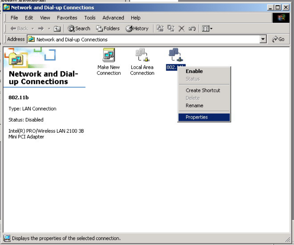
1. Open Network Connections.
- Win 2000: Click on Start, Settings, then Network, and Dial-up
Connections.
- Win XP: Click on Start, Connect To, then Show All Connections.
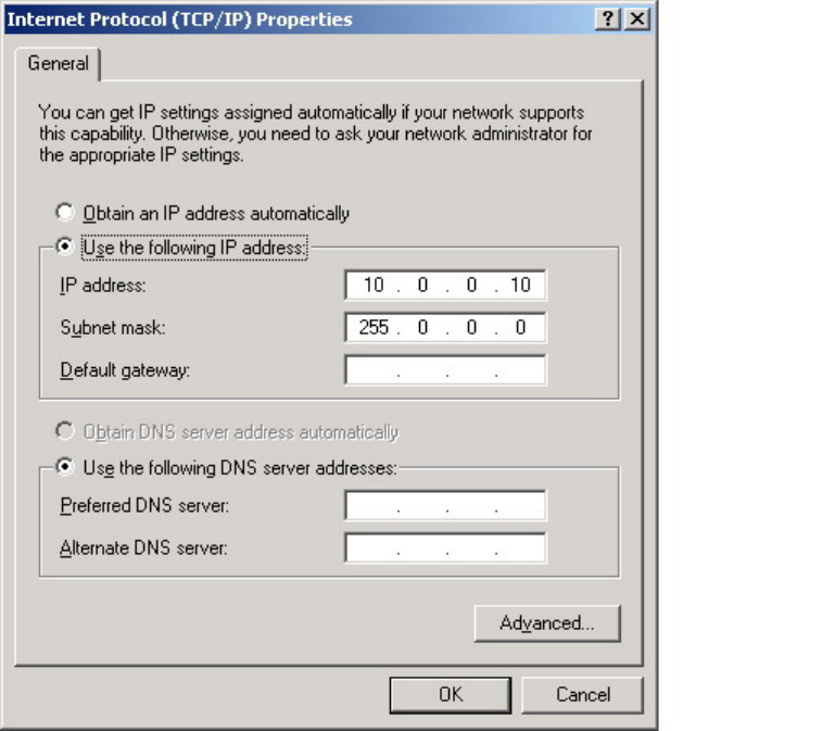
2. Right click on Local Area Connection and then select Properties.
3. Select Internet Protocol (TCP/IP) and then click on Properties.
4. Click on Use the following IP address.
5. Type in the following IP address: 10.0.0.10~100.
6. For the Subnet Mask, type: 255.0.0.0.
7. Click OK to close the TCP/IP properties panel.
8. Click OK to close the Network panel and the changes will take
effect when this panel is closed.
1. Open a web browser and type in the following address:
10.0.0.2.
2. A login screen should appear. Type the login name: admin and the password: admin.
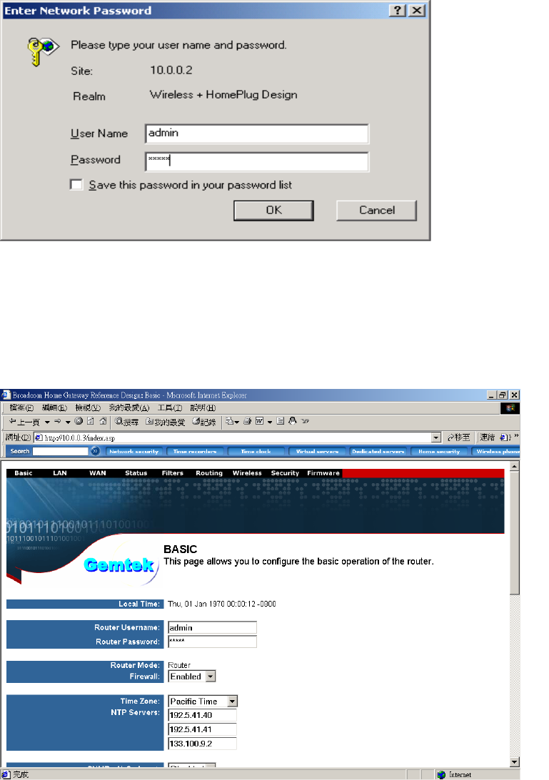
3. The basic information screen should now appear in the browser window.
4. Click on the Powerline Tab.
5. The default HomePlug password is HomePlug. If your existing
HomePlug password is different, change this password accordingly.
Setting up the IP address on the GT Powerline Router
1. Click on the LAN Tab.
2. The default IP address of GT Powerline Route is 10.0.0.2. You can change this IP address to
matches your network
configuration (Example: 192.168.1.10)
3. You can change the Subnet mask and Gateway values as well.
At this point, you will need to change the PCs IP address back to it's
original settings. Follow these steps depending on your operating system.
Windows 98 SE / ME
1. Click on Start, then Settings, and then Control Panel.
2. Double click on the Network icon.
3. Select the TCP/IP Protocol entry.
4. Click on the Properties button.
5. Select the IP Address tab.
6. Select Obtain an IP Address Automatically.
7. Click OK to close the TCP/IP properties panel.
8. Click OK to close the Network panel.
9. Restart the PC.
Windows 2000 / XP
1. Open Network Connections.
- Win 2000: Click on Start, Settings, then Network and Dial-up
Connections.
- Win XP: Click on Start, Connect To, then Show All Connections.
2. Right click on Local Area Connection and then select Properties.
3. Select Internet Protocol (TCP/IP) and then click on Properties.
4. Select Obtain an IP Address Automatically and Obtain a DNS server
automatically.
5. Click OK to close the TCP/IP properties panel.
6. Click OK to close the Network panel.
The changes will take a few minutes.
Open a new web browser and type in the new IP address of ALL1681 to
ensure the changes worked.
Other Features
Wireless Tab
- Change the value for the SSID ( Note: If you change the value here,
you will also need to change the value on each PC.)
- Change the Country where you are
- Change the Band
- Change the Channel
- Change the transmission Mode
- Change the Transmission Mb rates
- Change the Multicast rates
- Enable XPress Technology
- Enable Afterburner Technology
- Change WDS Operation Mode (Note: It depend on you network environment)
- Enable MAC Restrict Mode (Note: Type the MAC address of devices you want to restrict here)
Security Tab
Here you can adjust the following:
- Setup the information of External/ Internal RADIUS Server
- Enable Wired 802.1x
- Open the Network Authentication
- Enable WEP Encryption
- Setup WPA Pre-Shared Keys
Firmware Tab
- Here you can update the new firmware. (Note: You should download the new firmware first)
Routing tab
Filter tab
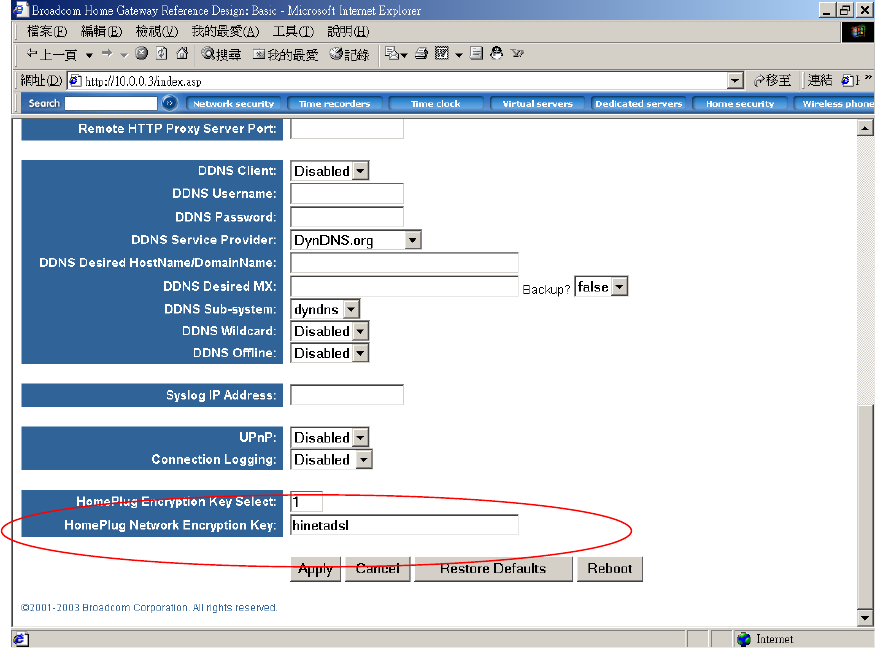
1.2 Homeplug network Encryption key setting
1. Set the Homeplug network encryption key
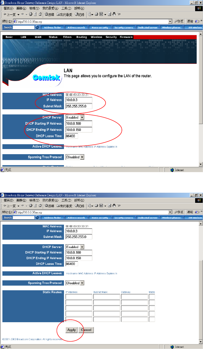
LAN setting
1. Set the LAN IP and subnet mask
2. Set the LAN DHCP server enable or disable
3. After setting press apply to let the setting work
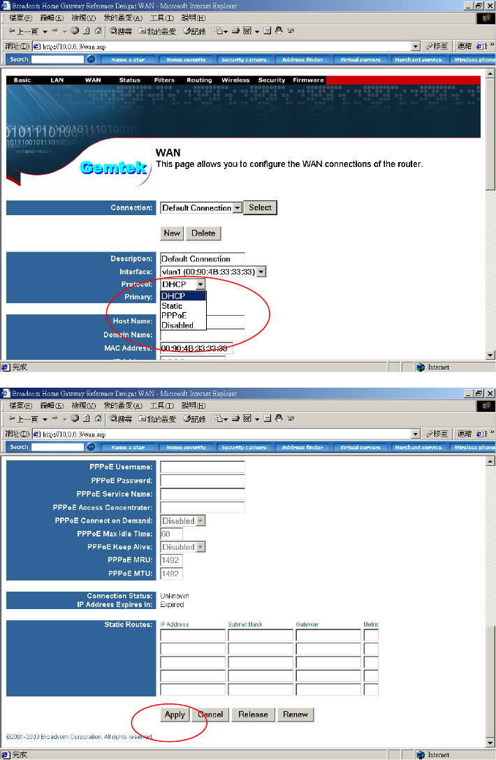
WAN SETTING
1. The WAN can set to DHCP client, static IP, PPPoE or Disabled
2. After setting ok, press apply to let the setting work
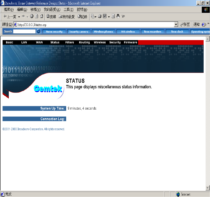
Router Status
Show the router status information
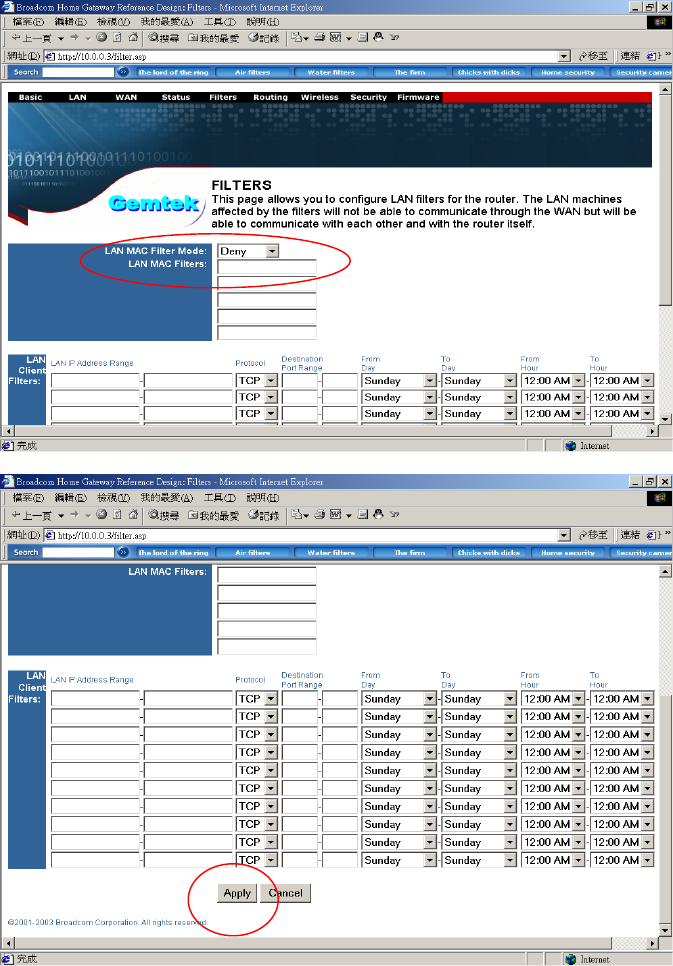
Filters Setting
1. Set LAN MAC filter to allow or deny. to use the router
2. After setting , press apply to let the setting work
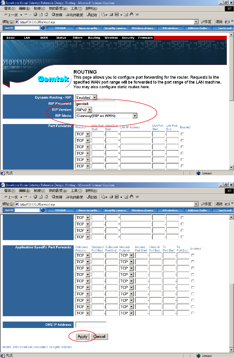
Routing setting
1. Set the router routing mode to RIPV1 or RIPV2
2. After setting , press apply to let the setting work
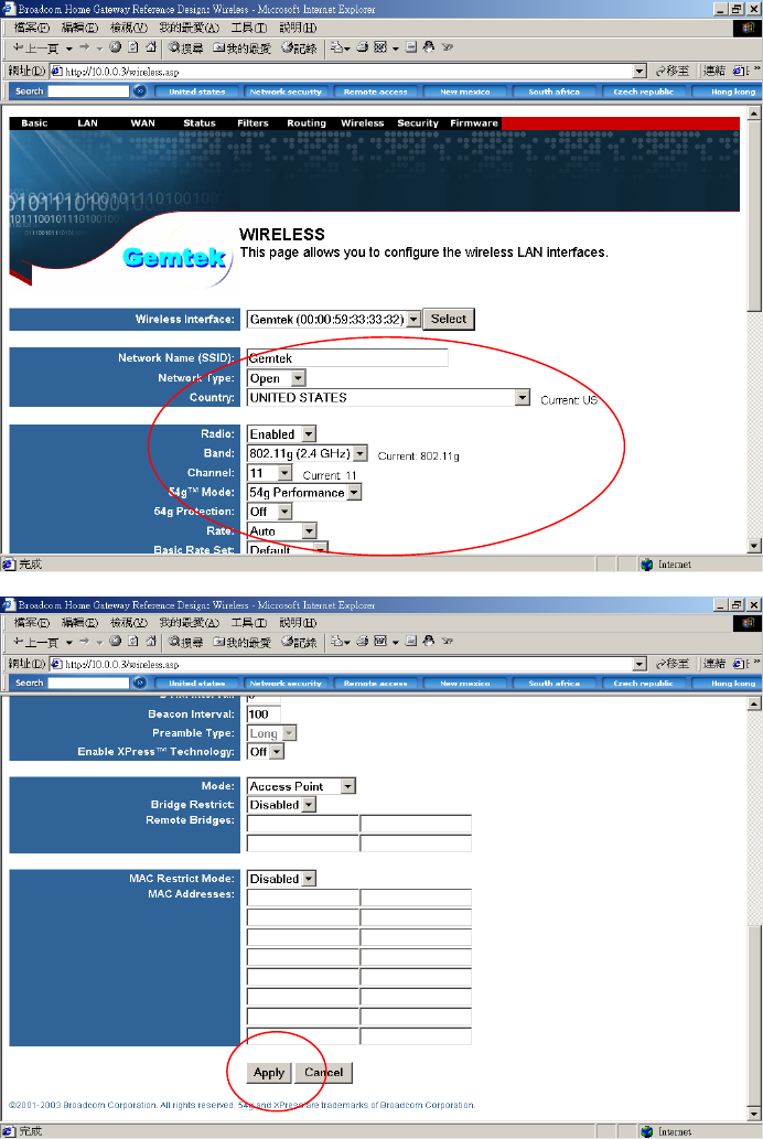
Wireless Setting
1. Set the wireless SSID, country, channel, etc. (Default SSID was “default”)
2. After setting , press apply to let the setting work
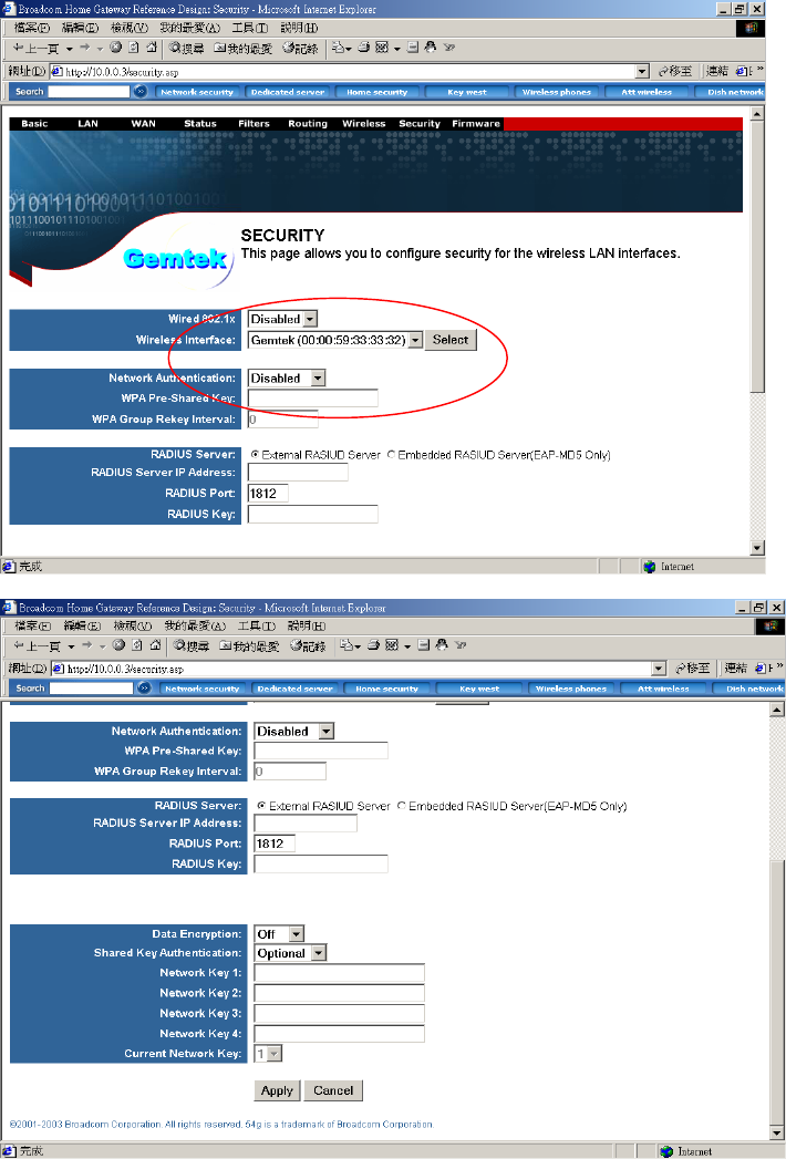
Security
1. Set the router wireless security (802.1X, WEP, etc…)
2. After setting , press apply to let the setting work
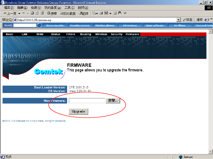
Upgarde Firmware
1. Upgrade the router firmware
2. The router will auto reboot after upgraded
Notes
Appendix A: Features
Supports 802.11g wireless LAN
Support Home-Plug 1.0 Power-line network
Simultaneously operation on 802.11g wireless LAN and Power-line network
Enhanced Security Management Functions: Wireless/Wired 802.1x, Embedded RADIUS Server
Supports 64/128 bits WEP Key in wireless 802.11g LAN
Supports 56-bits DES Key for Power-line network
The wireless 11g operation provide data rate at 6, 9, 12, 18, 24, 36, 48, 54Mbps with auto
fallback at 11b data rate at 1, 2, 5.5, and 11Mbps.
For 802.11g, support 11 channels for North America, 13 for Europe (ETSI) and 14 for Japan
Supports Wireless Distribution System (WDS) –Wireless Bridge, Wireless Repeater
Supports 802.11i – WPA / TKIP, AES, PSK
Easily Configurable through your networked PC’s Web browser
Administrators can block specific internal users’ Internet access with 802.1x
TCP, UDP, ICMP, IGMP
IEEE 802.1D (self learning transparent bridge)
IEEE 802.1D Spanning Tree Protocol
SNMP V1/V2c Agent
Remote administration and remote upgrades available over the Internet
Supports Traffic and Event Logging
Appendix B: Limited Warranty
Gemtek warrants that (a) the hardware components of the Gemtek product will be free from
defects in materials and workmanship under normal use for one (1) year from the date of
purchase, and (b) the software components will perform substantially in accordance with
Gemtek's published specifications for ninety (90) days from the date of purchase, but does not
warrant that the software will be error-free or free of all defects. If a defect or nonconformance
exists during the applicable warranty period, at its option Gemtek will repair or replace the
defective parts or nonconforming software using new or refurbished replacement parts or media
at no additional charge to you. This warranty extends only to you, the original purchaser and is
not transferable to any subsequent purchasers.
This Limited Warranty does not extend to any product not purchased or licensed from Gemtek or
its authorized resellers or retailers. This Limited Warranty does not apply: (a) to damage caused
by accident, abuse, misuse, misapplication, unusual electrical fluctuation, or improper
transportation upon return to Gemtek; (b) if you use parts not manufactured or sold by Gemtek;
or (c) to damage caused by modification of the product or as a result of service by anyone other
Appendix C: FCC Statement
This equipment has been tested and found to comply with the limits for a Class B digital device,
pursuant to part 15 of
FCC Rules. These limits are designed to provide reasonable protection against harmful
interference in a residential installation.
This equipment generates, uses and can radiate radio frequency energy and, if not installed and
used in accordance
with the instructions, may cause harmful interference to radio communications. However, there is
no guarantee
that interference will not occur in a particular installation. If this equipment does cause harmful
interference to radio or
television reception, which can be determined by turning the equipment off and on, the user is
encouraged to try to correct
the interference by one or more of the following measures:
- Reorient or relocate the receiving antenna.
- Increase the separation between the equipment and receiver.
- Connect the equipment into an outlet on a circuit different from that to which the
receiver is connected.
- Consult the dealer or an experienced radio/TV technician for help.
This device complies with Part 15 of FCC Rules.
Operation is subject to the following two conditions:
(1) This device may not cause harmful interference, and
(2) This device must accept any interference received, including interference that may cause
undesired operation.
FCC Caution: Any changes or modifications not expressly approved by the party responsible for
compliance could void the user's authority to operate this equipment.
FCC RF Radiation Exposure Statement:
This equipment complies with FCC RF radiation exposure limits set forth for an uncontrolled
environment. This equipment should be installed and operated with a minimum distance of 20
centimeters between the radiator and your body.
This transmitter must not be co-located or operating in conjunction with any other antenna or
transmitter.