GemTek Technology ISA570 Cisco ISA570 Integrated Security Appliance with WiFi User Manual shiner admin guide
Gemtek Technology Co., Ltd. Cisco ISA570 Integrated Security Appliance with WiFi shiner admin guide
User Manual

Cisco Small Business
ISA500 Series Integrated Security Appliance
ADMINISTRATION
GUIDE

© 2011 Cisco Systems, Inc. All rights reserved. OL-23370-01
Cisco and the Cisco Logo are trademarks of Cisco Systems, Inc. and/or its affiliates in the U.S. and other countries. A listing of Cisco's trademarks can be found
at www.cisco.com/go/trademarks. Third party trademarks mentioned are the property of their respective owners. The use of the word partner does not imply
a partnership relationship between Cisco and any other company. (1005R)

3
OL-23370-01
Federal Communication Commission Interference Statement
(For ISA570 and ISA570W)
This equipment has been tested and found to comply with the limits for a Class A digital device, pursuant
to Part 15 of the FCC Rules. These limits are designed to provide reasonable protection against harmful
interference when the equipment is operated in a commercial environment. This equipment generates,
uses, and can radiate radio frequency energy and, if not installed and used in accordance with the
instruction manual, may cause harmful interference to radio communications. Operation of this
equipment in a residential area is likely to cause harmful interference in which case the user will be
required to correct the interference at his own expense.
(For ISA550 and ISA550W)
This equipment has been tested and found to comply with the limits for a Class B digital device, pursuant
to Part 15 of the FCC Rules. These limits are designed to provide reasonable protection against harmful
interference in a residential installation. This equipment generates, uses and can radiate radio frequency
energy and, if not installed and used in accordance with the instructions, may cause harmful interference
to radio communications. However, there is no guarantee that interference will not occur in a particular
installation. If this equipment does cause harmful interference to radio or television reception, which
can be determined by turning the equipment off and on, the user is encouraged to try to correct the
interference by one of the following measures:
•Reorient or relocate the receiving antenna.
•Increase the separation between the equipment and receiver.
•Connect the equipment into an outlet on a circuit different from that to which the receiver is
connected.
•Consult the dealer or an experienced radio/TV technician for help.
FCC Caution: Any changes or modifications not expressly approved by the party responsible for
compliance could void the user's authority to operate this equipment.
This device complies with Part 15 of the FCC Rules. Operation is subject to the following two
conditions: (1) This device may not cause harmful interference, and (2) this device must accept any
interference received, including interference that may cause undesired operation.
IMPORTANT NOTE:
FCC Radiation Exposure Statement: (For ISA550W and ISA570W)
This equipment complies with FCC radiation exposure limits set forth for an uncontrolled environment.
This equipment should be installed and operated with minimum distance 20cm between the radiator &
your body.
This transmitter must not be co-located or operating in conjunction with any other antenna or transmitter.
The availability of some specific channels and/or operational frequency bands are country dependent
and are firmware programmed at the factory to match the intended destination. The firmware setting is
not accessible by the end user.
Industry Canada statement:
This device complies with RSS-210 of the Industry Canada Rules. Operation is subject to the following
two conditions: (1) This device may not cause harmful interference, and (2) this device must accept any
interference received, including interference that may cause undesired operation.

4
OL-23370-01
Ce dispositif est conforme à la norme CNR-210 d'Industrie Canada applicable aux appareils radio
exempts de licence. Son fonctionnement est sujet aux deux conditions suivantes: (1) le dispositif ne doit
pas produire de brouillage préjudiciable, et (2) ce dispositif doit accepter tout brouillage reçu, y compris
un brouillage susceptible de provoquer un fonctionnement indésirable.
IMPORTANT NOTE:
Canada Radiation Exposure Statement: (For ISA550W and ISA570W)
This equipment complies with Canada radiation exposure limits set forth for an uncontrolled
environment. This equipment should be installed and operated with minimum distance 20cm between
the radiator and your body.
NOTE IMPORTANTE: (Pour l'utilisation de dispositifs mobiles)
Déclaration d'exposition aux radiations:
Cet équipement est conforme aux limites d'exposition aux rayonnements IC établies pour un
environnement non contrôlé. Cet équipement doit être installé et utilisé avec un minimum de 20 cm de
distance entre la source de rayonnement et votre corps.
This device has been designed to operate with an antenna having a maximum gain of 1.8 dBi. Antenna
having a higher gain is strictly prohibited per regulations of Industry Canada. The required antenna
impedance is 50 ohms.
Under Industry Canada regulations, this radio transmitter may only operate using an antenna of a type
and maximum (or lesser) gain approved for the transmitter by Industry Canada. To reduce potential radio
interference to other users, the antenna type and its gain should be so chosen that the equivalent
isotropically radiated power (e.i.r.p.) is not more than that necessary for successful communication.
(Le manuel d'utilisation de dispositifs émetteurs équipés d'antennes amovibles doit contenir les
informations suivantes dans un endroit bien en vue:)
Ce dispositif a été conçu pour fonctionner avec une antenne ayant un gain maximal de 1.8 dBi. Une
antenne à gain plus élevé est strictement interdite par les règlements d'Industrie Canada. L'impédance
d'antenne requise est de 50 ohms.
Conformément à la réglementation d'Industrie Canada, le présent émetteur radio peutfonctionner avec
une antenne d'un type et d'un gain maximal (ou inférieur) approuvé pourl'émetteur par Industrie Canada.
Dans le but de réduire les risques de brouillage radioélectriqueà l'intention des autres utilisateurs, il faut
choisir le type d'antenne et son gain de sorte que lapuissance isotrope rayonnée équivalente (p.i.r.e.) ne
dépasse pas l'intensité nécessaire àl'établissement d'une communication satisfaisante.
UL/CB
Rack Mount Instructions - The following or similar rack-mount instructions are included with the
installation instructions:
A) Elevated Operating Ambient - If installed in a closed or multi-unit rack assembly, the operating
ambient temperature of the rack environment may be greater than room ambient. Therefore,
consideration should be given to installing the equipment in an environment compatible with the
maximum ambient temperature (Tma) 40 degree C specified by the manufacturer.
B) Reduced Air Flow - Installation of the equipment in a rack should be such that the amount of air flow
required for safe operation of the equipment is not compromised.
C) Mechanical Loading - Mounting of the equipment in the rack should be such that a hazardous
condition is not achieved due to uneven mechanical loading.

5
OL-23370-01
D) Circuit Overloading - Consideration should be given to the connection of the equipment to the supply
circuit and the effect that overloading of the circuits might have on overcurrent protection and supply
wiring. Appropriate consideration of equipment nameplate ratings should be used when addressing this
concern.

6
OL-23370-01

Cisco ISA500 Series Integrated Security Appliance Administration Guide 1
Contents
Chapter 1: Getting Started 12
Introduction 12
Feature Overview 13
Device Overview 14
Front Panel 14
Back Panel 17
Installation 18
Before You Begin 19
Installation Options 19
Placement Tips 19
Wall Mounting 20
Rack Mounting 21
Hardware Installation 22
Getting Started with the Configuration Utility 23
Launching the Configuration Utility 23
Navigating Through the Configuration Utility 24
Using the Help System 25
Using the Management Buttons 25
About the Default Settings 25
Performing Common Configuration Tasks 27
Changing the User Name and Password of the Default Administrator Account
at Your First Login 27
Saving Your Configuration 28
Upgrading the Firmware if needed 29
Resetting the Device 30
Chapter 2: Wizards 32
Using the Startup Wizard 32
Using the Wireless Wizard to Configure the Wireless Settings for ISA550W and
ISA570W 40
Using the Wireless Wizard to Configure the Wireless Settings 41
Configuring the SSID for Intranet WLAN Access 43
Configuring the SSID for Guest WLAN Access 44
Configuring the SSID for Guest WLAN Access (Captive Portal) 45

Cisco ISA500 Series Integrated Security Appliance Administration Guide 2
Contents
Using the DMZ Wizard to Configure the DMZ Settings 46
Using the DMZ Wizard to Configure the DMZ Settings 47
Configuring the DMZ 48
Configuring the DMZ Services 49
Using the Dual WAN Wizard to Configure the WAN Redundancy Settings 51
Using the Site-to-Site Wizard to Establish the Site-to-Site VPN Tunnels 53
Using the Site-to-Site Wizard to Establish the Site-to-Site VPN tunnel 53
Configuring the IKE Policies 55
Configuring the Transform Policies 57
Using the Remote Access Wizard to Establish the IPSec VPN Tunnels or SSL VPN
Tunnels for Remote Access 58
Using Cisco IPSec VPN to Establish the IPSec VPN Tunnels 58
Configuring the Cisco IPSec VPN User Groups 63
Using SSL VPN to Establish the SSL VPN Tunnels 63
Configuring the SSL VPN Group Policies 66
Configuring the SSL VPN User Groups 69
Chapter 3: Status 70
System Status 70
Interface Status 74
ARP Table 74
DHCP Pool Assignment 75
Interface 75
Interface Statistics 77
Wireless Status for ISA550W and ISA570W 79
Wireless Status 80
Client Status 81
Active Users 81
VPN Status 81
IPSec VPN Status 82
SSL VPN Status 83
Reports 85
Reports of Event Logs 86
Reports of WAN Bandwidth 87
Reports of Security Services 87

Cisco ISA500 Series Integrated Security Appliance Administration Guide 3
Contents
Web Security Blocked Report 88
Anti-Virus Report 88
Email Security Report 89
Network Reputation Report 90
IPS Policy Protocol Inspection Report 90
IM and P2P Blocking Report 91
Process Status 92
Resource Utilization 92
Chapter 4: Networking 94
Configuring IP Routing Mode 95
Port Management 95
Viewing the Status of Physical Interfaces 95
Configuring the Physical Interfaces 96
Configuring 802.1X Access Control on Physical Ports 98
Configuring the Port Mirroring 100
Configuring the WAN 101
Configuring the Primary WAN 101
Configuring the Secondary WAN 104
Configuring the Network Addressing Mode 106
Configuring the PPPoE Profiles 111
Configuring the WAN Redundancy 112
Loading Balancing for WAN Redundancy 113
Load Balancing with Policy-based Routing Configuration Example 115
Failover for WAN Redundancy 116
Routing Table for WAN Redundancy 117
Configuring the Link Failover Detection 117
Configuring the VLAN 118
Configuring the VLANs 119
Configuring DHCP Reserved IPs 122
Configuring the DMZ 123
Configuring the Zones 127
Security Levels for Zones 128
Predefined Zones 128

Cisco ISA500 Series Integrated Security Appliance Administration Guide 4
Contents
Configuring the Zones 129
Configuring the Routing 130
Configuring the Routing Mode 131
Viewing the Routing Table 131
Configuring the Static Routing 132
Configuring the Dynamic Routing 133
Configuring Policy-based Routing Settings 134
Priority of Routing Rules 136
Dynamic DNS 136
IGMP 138
VRRP 139
Configuring the Quality of Service 140
General QoS Settings 141
Configuring the WAN QoS 141
Managing the WAN Bandwidth for Upstream Traffic 142
Configuring the WAN Queue Settings 142
Configuring the Traffic Selectors for WAN Interfaces 144
Configuring the WAN QoS Policy Profiles 145
Mapping the WAN QoS Policy Profiles to WAN Interfaces 146
Configuring the LAN QoS 147
Configuring the LAN Queue Settings 147
Configuring the LAN QoS Classification Methods 148
Mapping CoS to LAN Queue 149
Mapping DSCP to LAN Queue 149
Configuring Default CoS 149
Configuring the Wireless QoS 150
Default Wireless QoS Settings 150
Configuring the Wireless QoS Classification Methods 151
Mapping CoS to Wireless Queue 151
Mapping DSCP to Wireless Queue 151
Address Management 152
Configuring the Addresses 152
Configuring the Group Addresses 153
Service Management 154
Configuring the Services 154

Cisco ISA500 Series Integrated Security Appliance Administration Guide 5
Contents
Configuring the Group Services 155
Chapter 5: Wireless Configuration for ISA550W and ISA570W 157
Configuring the Radio Settings 157
Basic Radio Settings 158
Advanced Radio Settings 160
Configuring the Access Points 162
Configuring the Security Mode 162
Controlling the Wireless Access Based on MAC Addresses 169
Mapping the SSID to VLAN 170
Configuring the SSID Schedule 171
Configuring Wi-Fi Protected Setup 172
Configuring Wireless Rogue AP Detection 173
Configuring Wireless Captive Portal 174
Chapter 6: Firewall 177
Configuring the Firewall Access Rules to Control Inbound and Outbound Traffic
178
Default Firewall Settings 178
Priorities of Firewall Access Rules 180
Preliminary Tasks for Configuring the Firewall Access Rules 180
General Settings for Configuring the Firewall Access Rules 181
Configuring a Firewall Access Rule 183
Configuring a Firewall Access Rule to Allow the Multicast Traffic 185
Configuring the Firewall Schedule 186
Firewall Access Rule Configuration Examples 187
Configuring the NAT Rules to Securely Access a Remote Network 192
Configuring Dynamic PAT Rules 193
Configuring Static NAT Rules 194
Configuring Port Forwarding Rules 195
Configuring Port Triggering Rules 196
Configuring Advanced NAT Rules 197
Viewing NAT Translation Status 199

Cisco ISA500 Series Integrated Security Appliance Administration Guide 6
Contents
Priorities of NAT Rules 200
Configuring the Session Settings 200
Configuring the Content Filtering to Control Access to Internet 201
Configuring the Content Filtering Policy Profiles 201
Configuring the Website Access Control List 203
Mapping the Content Filtering Policy Profiles to Zones 204
Configuring Advanced Settings 204
Configuring the MAC Filtering to Permit or Block Traffic 205
Configuring the IP/MAC Binding to Prevent Spoofing 206
Configuring the Attack Protection 207
Configuring the Application Level Gateway 209
Chapter 7: Security Services 210
Managing the Security Services 210
About the Security Services 211
Security License 212
Priority of Security Services 212
Managing the Security Services 212
Viewing the Security Service Reports 214
Intrusion Prevention Service 214
General IPS Settings 215
Configuring the IPS Policy and Protocol Inspection 216
Blocking the Instant Messaging and Peer-to-Peer Applications 218
Anti-Virus 220
Configuring the Anti-Virus 220
Configuring the Email Notification 223
Configuring the HTTP Notification 224
Email Reputation Filter 224
Web URL Filter 226
Configuring the Web URL Filter Policy Profiles 226
Configuring the Whitelist and Blacklist of Websites 227
Mapping the Web URL Filter Policy Profiles to Zones 228

Cisco ISA500 Series Integrated Security Appliance Administration Guide 7
Contents
Configuring Advanced Web URL Filter Settings 229
Web Reputation Filter 230
Network Reputation 231
Chapter 8: VPN 232
About VPN 232
Configuring the Cisco IPSec VPN Server 233
Cisco VPN Client Compatibility 234
Configuring the Group Policies for Cisco IPSec VPN Server 235
Configuring the Cisco IPSec VPN Client 238
Restrictions for Cisco IPSec VPN Client 239
Benefits of the Cisco IPSec VPN Client Feature 239
Modes of Operation 240
Client Mode 240
Network Extension Mode 241
General Settings 242
Configuring the Group Policies for Cisco IPSec VPN Client 243
Configuring the Site-to-Site VPN 246
Configuration Tasks to Establish a Site-to-Site VPN 246
General Site-to-Site VPN Settings 247
Configuring the IPSec VPN Policies 248
Configuring the IPSec IKE Policies 254
Configuring the IPSec Transform Policies 256
Configuring the SSL VPN 257
Elements of the SSL VPN 258
Configuration Tasks to Establish a SSL VPN Tunnel 259
Installing the Cisco AnyConnect VPN Client on User’s PC 260
Importing the Certificates for User Authentication 260
Configuring the SSL VPN Users 260
Configuring the SSL VPN Gateway 261
Configuring the SSL VPN Group Policies 263
Configuring the SSL VPN Portal 266
Configuring the L2TP Server 266

Cisco ISA500 Series Integrated Security Appliance Administration Guide 8
Contents
Configuring the VPN Passthrough 268
Viewing the VPN Status 268
Monitoring the IPSec VPN Status 269
Monitoring the SSL VPN Status 270
Chapter 9: User Management 273
About the Users and Groups 273
Available Services for User Groups 273
Default User and Group 274
Preempt the Administrators 274
Configuring the Users and Groups 275
Configuring Local Users 275
Configuring Local User Groups 276
Configuring the User Authentication Settings 277
Authentication Methods for User Login 278
Using Local Database for Authentication 279
Using RADIUS Server for Authentication 279
Using Local Database and RADIUS Server for Authentication 282
Using LDAP for Authentication 283
Using Local Database and LDAP for Authentication 286
Configuring the User Session Settings 286
Viewing Active User Sessions 287
Chapter 10: Device Management 288
Remote Management 289
Administration 290
Changing the User Name and Password for the Default Administrator Account
290
Configuring the User Session Settings 291
SNMP 292
Configuration Management 294
Saving your Current Configurations 294
Restoring your Settings from a Saved Configuration File 295

Cisco ISA500 Series Integrated Security Appliance Administration Guide 9
Contents
Reverting to the Factory Default Settings 296
Firmware Management 297
Viewing the Firmware Information 297
Checking for New Firmwares 298
Upgrading the Firmware 299
Using the Secondary Firmware 300
Firmware Auto Fall Back Mechanism 301
Using the Rescue Mode to Recover the System 302
Rebooting the Security Appliance 302
Log Management 302
Configuring the Log Settings 303
Configuring the Log Facilities 305
Viewing the Logs 306
Managing the Security License 307
Checking the License Status 308
Renewing the Security License 309
Managing the Certificates for Authentication 310
Viewing the Certificate Status 310
Managing the Certificates 311
Exporting the Certificates to Local PC 312
Exporting the Certificates to a USB Device 313
Importing the Certificates from Your Local PC 313
Importing the Certificates from a Mounted USB Device 314
Importing the Signed Certificate for CSR from Your Local PC 314
Generating New Certificate Signing Requests 315
Configuring the Email Alert Settings 316
Configuring the RADIUS Servers 319
Configuring the Time Zone 320
Device Discovery 321
UPnP 321
Bonjour 322
CDP 323
LLDP 324

Cisco ISA500 Series Integrated Security Appliance Administration Guide 10
Contents
Diagnosing the Device 324
Ping 325
Tracert 325
DNS Lookup 326
Packet Capture 326
System Diagnostics 327
Measuring and Limiting Traffic with the Traffic Meter 328
Configuring the ViewMaster 330
Configuring the CCO Account 331
Configuring the Device Properties 332
Configuring the Debug Settings 332
Appendix A: Troubleshooting 333
Internet Connection 333
Date and Time 336
Pinging to Test LAN Connectivity 337
Testing the LAN Path from Your PC to Your Security Appliance 337
Testing the LAN Path from Your PC to a Remote Device 338
Restoring Factory Default Settings 339
Appendix B: Technical Specifications and Environmental Requirements 340
Appendix C: Factory Default Settings 343
Device Management 343
User Management 346
Networking 347
Wireless 352
VPN 353
Security Services 356
Firewall 357
Reports 359
Default Service Objects 360
Default Address Objects 363


1
Cisco ISA500 Series Integrated Security Appliance Administration Guide 12
Getting Started
This chapter provides the product overview and installation instruction to help you
to install the security appliance, and describes the default settings and some
basic configuration tasks to help you to begin configuring your security appliance.
It includes the following sections:
•Introduction, page 12
•Feature Overview, page 13
•Device Overview, page 14
•Installation, page 18
•Getting Started with the Configuration Utility, page 23
•About the Default Settings, page 25
•Performing Common Configuration Tasks, page 27
Introduction
The Cisco ISA500 Series Integrated Security Appliances are a set of Unified
Threat Management (UTM) security appliances that provide business class
security gateway solutions with zone-based firewall, site-to-site and remote
access VPN (including Cisco IPSec VPN and SSL VPN) support, and Internet
threat protection with multiple UTM security services. The ISA550W and
ISA570W include 802.11b/g/n access point capabilities.
The following table lists the available model numbers to help you become familiar
with your security appliance.

Getting Started
Feature Overview
Cisco ISA500 Series Integrated Security Appliance Administration Guide 13
1
Feature Overview
The features of the Cisco ISA500 Series Integrated Security Appliance are
compared in the following table.
Models Description Configuration
ISA550 Cisco ISA550 Integrated
Security Appliance
1 WAN port, 2 LAN ports, 4
configurable ports, and 1 USB 2.0 port
ISA550W Cisco ISA550 Integrated
Security Appliance with
WiFi
1 WAN port, 2 LAN ports, 4
configurable ports, 1 USB 2.0 port,
and 802.11b/g/n
ISA570 Cisco ISA570 Integrated
Security Appliance
1 WAN port, 4 LAN ports, 5
configurable ports, and 1 USB 2.0 port
ISA570W Cisco ISA570 Integrated
Security Appliance with
WiFi
1 WAN port, 4 LAN ports, 5
configurable ports, 1 USB 2.0 port,
and 802.11b/g/n
Feature ISA550 ISA550W ISA570 ISA570W
Firewall Throughput
(1000B)
150 Mbps 150 Mbps 300 Mbps 300 Mbps
Firewall Throughput
(IMIX)
70 Mbps 70 Mbps 150 Mbps 150 Mbps
IPSec VPN (large
packet)
75 Mbps 75 Mbps 150 Mbps 150 Mbps
Anti-Virus
Throughput
60 Mbps 60 Mbps 130 Mbps 130 Mbps
Intrusion Prevention
Service Throughput
80 Mbps 80 Mbps 150 Mbps 150 Mbps
UTM Throughput 45 Mbps 45 Mbps 120 Mbps 120 Mbps
Getting Started
Device Overview
Cisco ISA500 Series Integrated Security Appliance Administration Guide 14
1
Device Overview
Before you begin to use the security appliance, become familiar with the lights on
the front panel and the ports on the rear panel. It includes the following sections:
•Front Panel, page 14
•Back Panel, page 17
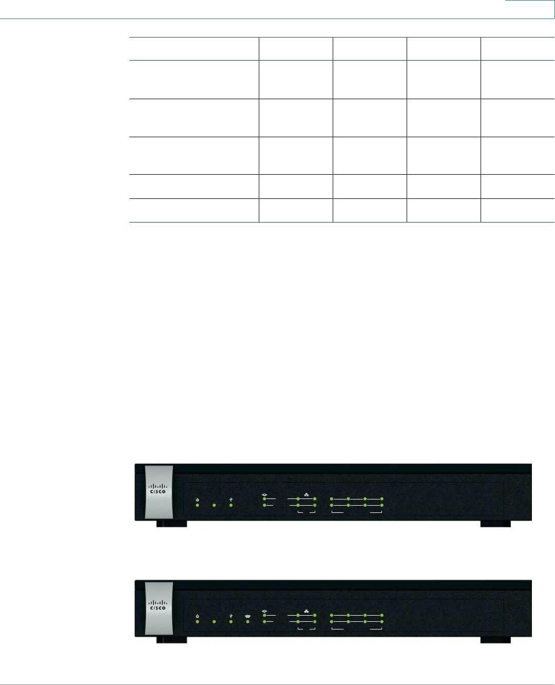
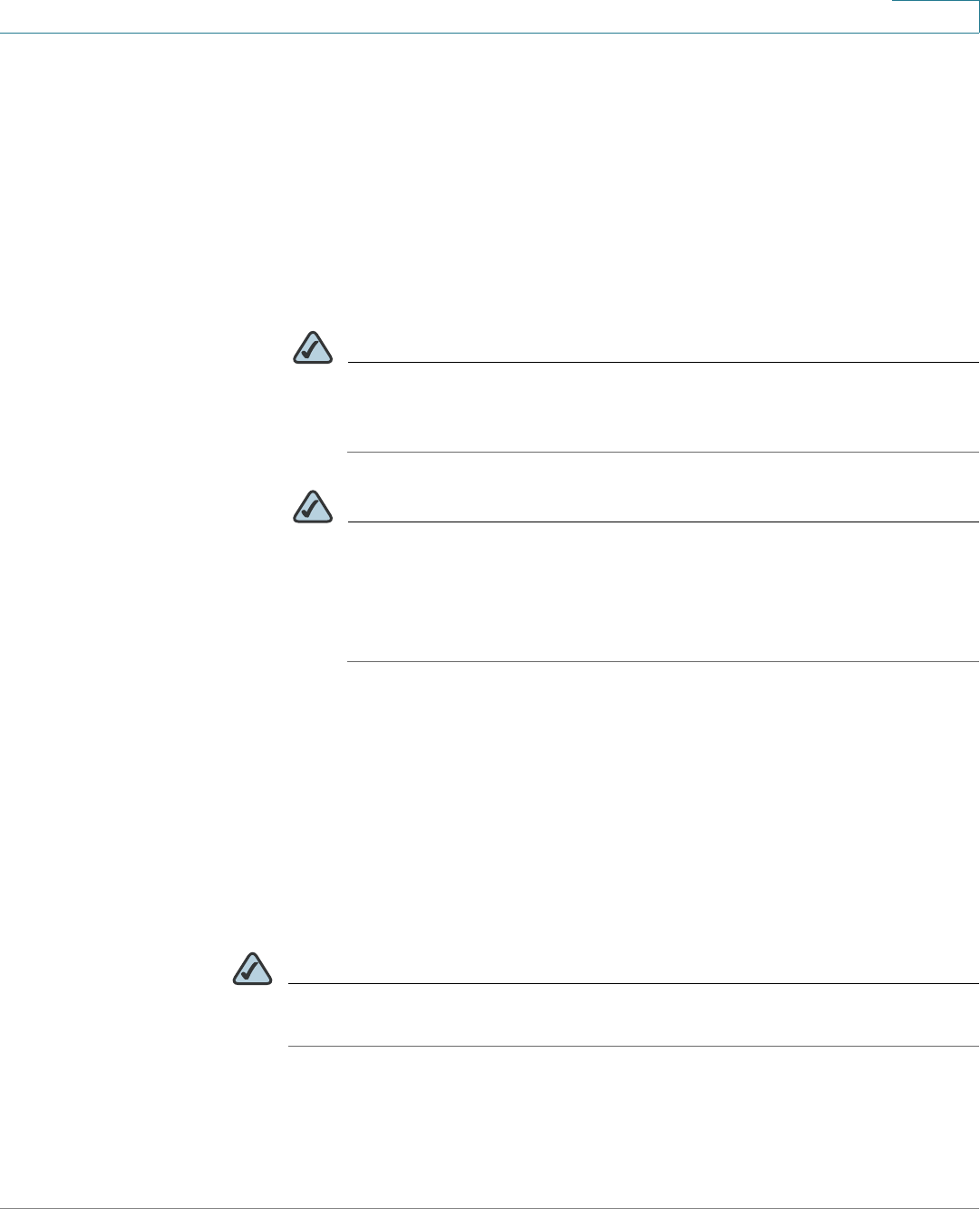
Front Panel
ISA550 Front Panel
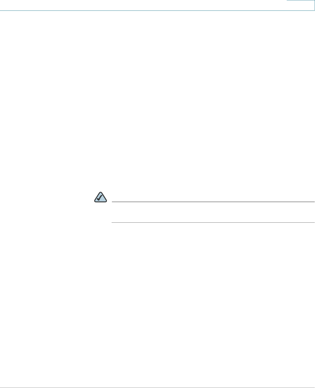
ISA550W Front Panel
Maximum
Concurrent Sessions
15,000 15,000 40,000 40,000
Sessions per
Seconds (cps)
2,500 2,500 3,000 3,000
Wireless (802.11b/g/
n)
No Yes No Yes
IPSec Tunnels 50 50 100 100
SSL VPN Tunnels 25 25 50 50
Feature ISA550 ISA550W ISA570 ISA570W
282351
Small Business
1
VPN USB WAN LAN CONFIGURABLEPOWER/SYS
SPEED
LINK /ACT
234567
ISA550 Cisco
281983
Small Business
1
VPN USB WAN LAN CONFIGURABLEPOWER/SYS
SPEED
LINK /ACT
234567
WLAN
ISA550W Cisco
Getting Started
Device Overview
Cisco ISA500 Series Integrated Security Appliance Administration Guide 15
1
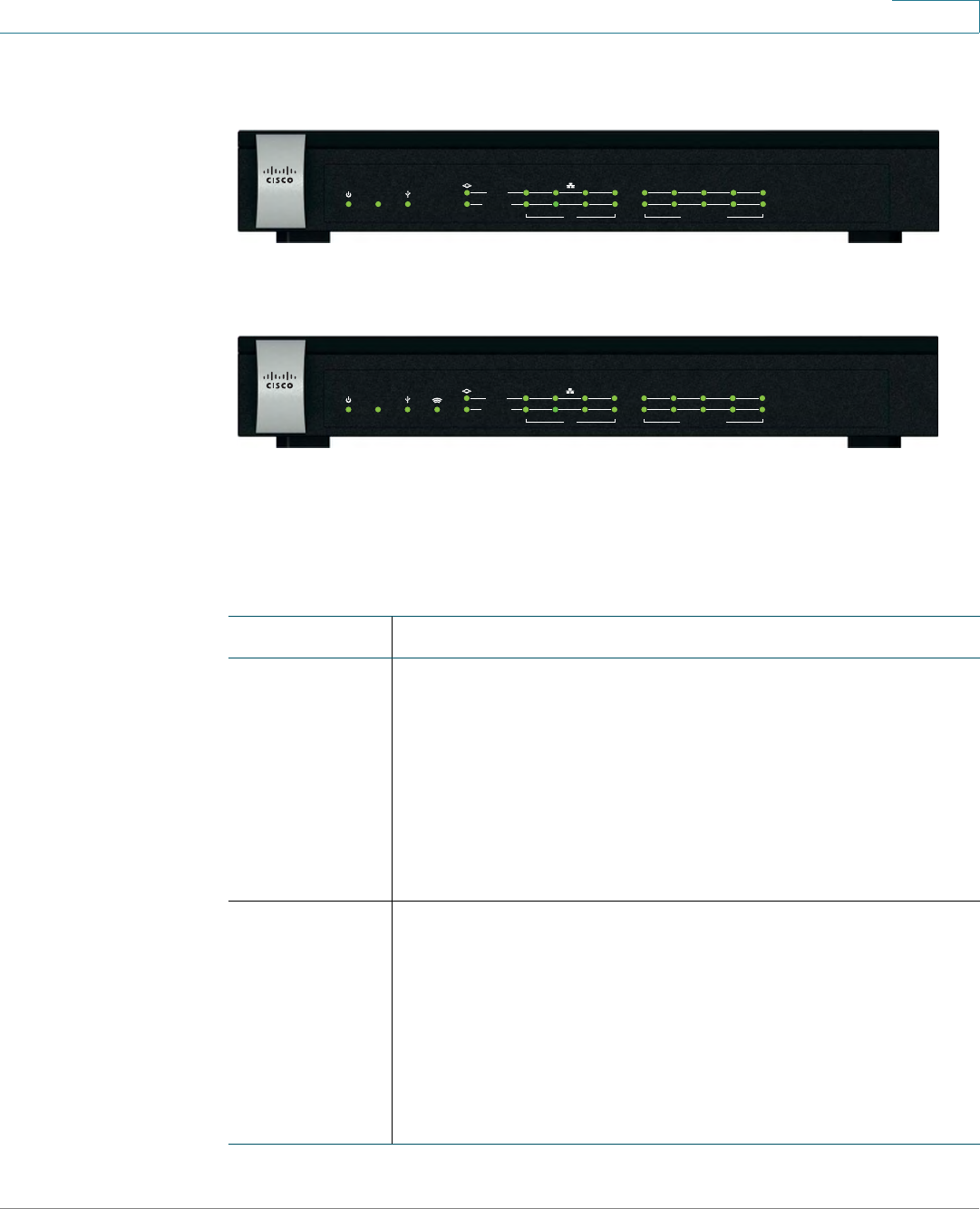
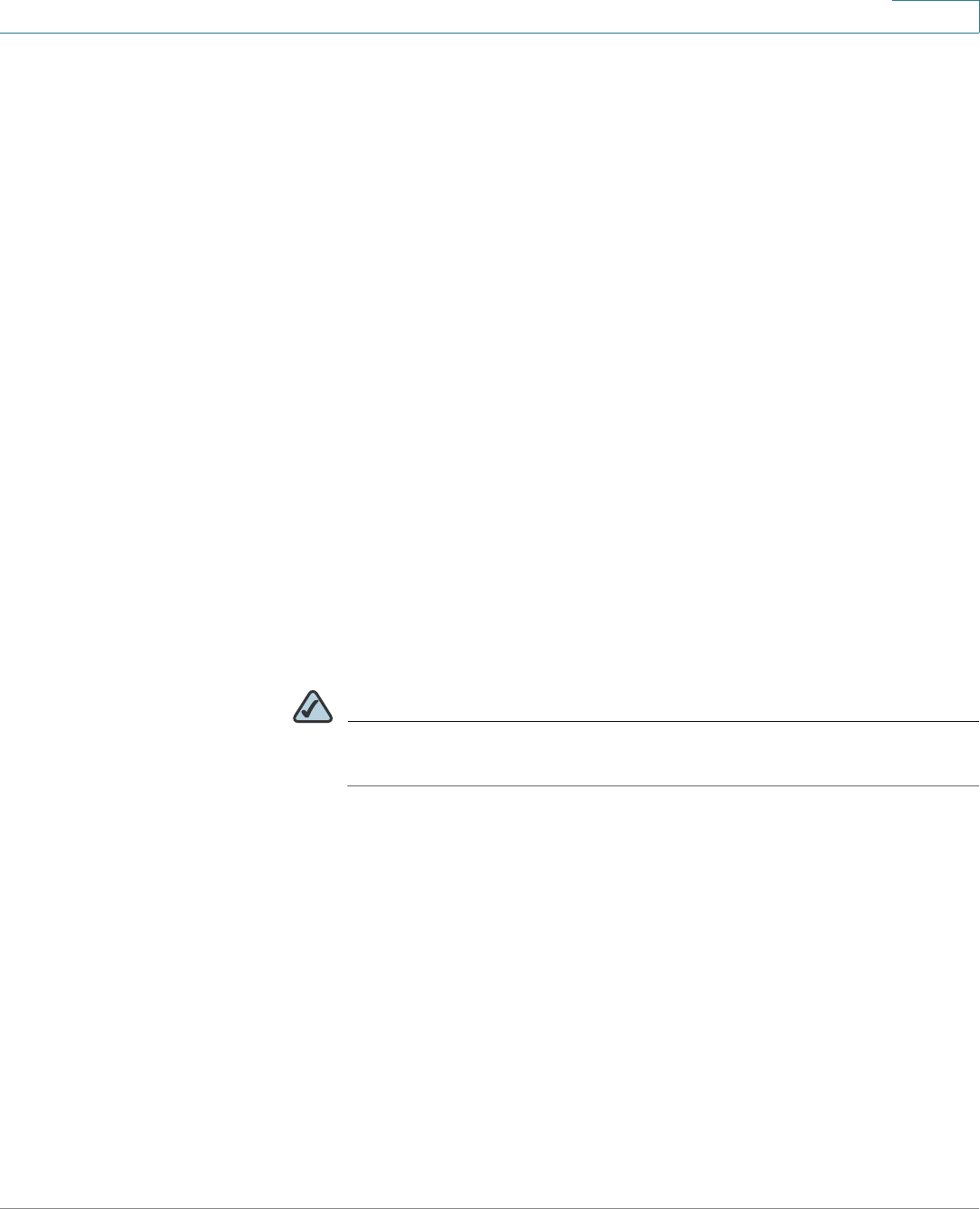
ISA570 Front Panel
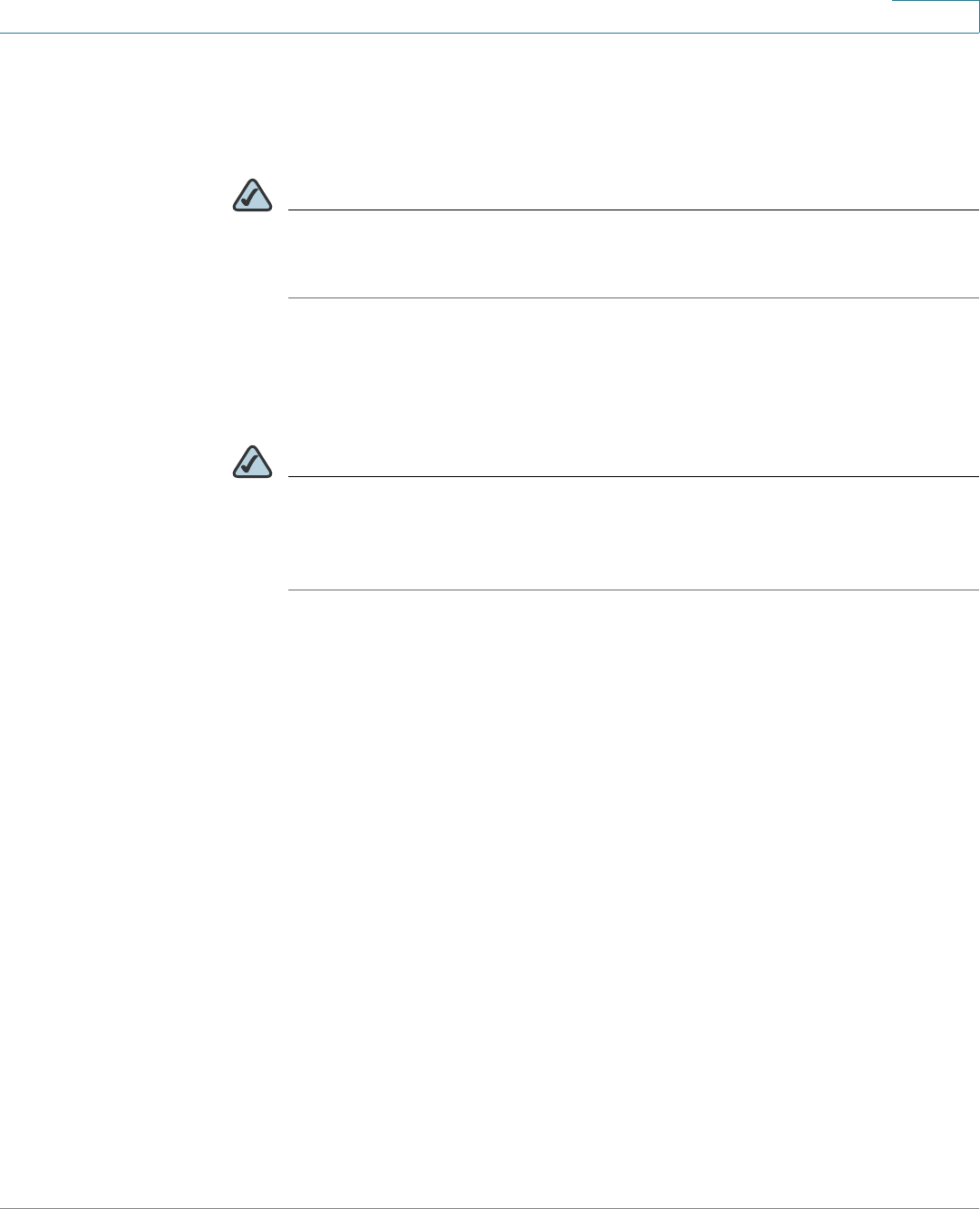
ISA570W Front Panel
Front Panel Lights
The following table describes the lights on the front panel of the security
appliance. These lights are used for monitoring system activity.
Small Business
1
VPN USB WAN LAN CONFIGURABLEPOWER/SYS
SPEED
LINK /ACT
910
2345678
282350
ISA570 Cisco
Small Business
1
VPN USB WAN LAN CONFIGURABLEPOWER/SYS
SPEED
LINK /ACT
910
2345678
WLAN
281980
ISA570W Cisco
Lights Description
POWER/SYS Indicates the power status and system status.
•Green lights when the system is powered on and
operates normally.
•Green flashes when the system is booting.
•Amber flashes when the system booting has a
problem, a device error occurs, or the system has a
problem.
VPN Indicates the Site-to-Site VPN connection status.
•Green lights when the Site-to-Site VPN tunnel is
established.
•Green flashes when attempting to establish the Site-to-
Site VPN tunnel.
•Amber flashes when the system is experiencing
problems setting up the Site-to-Site VPN connection.

Getting Started
Device Overview
Cisco ISA500 Series Integrated Security Appliance Administration Guide 16
1
NOTE The front panel of the ISA550 and ISA570 does not include the WLAN light.
USB Indicates the USB device status.
•Green lights when a USB device is detected and
operates normally.
•Green flashes when the USB device is transmitting and
receiving data.
WLAN
(ISA550W and
ISA570W
only)
Indicates the WLAN status.
•Green lights when the WLAN is enabled and
associated.
•Green flashes when the WLAN is transmitting and
receiving data.
SPEED Indicates the traffic rate of the associated port.
•Off when the traffic rate is 10 or 100 Mbps.
•Green lights when the traffic rate is 1000 Mbps.
LINK/ACT Indicates a connection is being made through the port.
•Green lights when the link is up.
•Green flashes when the port is transmitting and
receiving data.
Lights Description
Getting Started
Device Overview
Cisco ISA500 Series Integrated Security Appliance Administration Guide 17
1
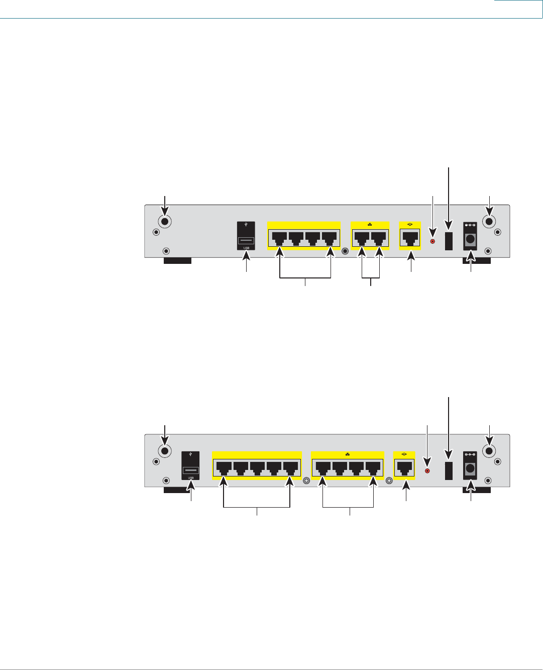
Back Panel
The back panel is where you connect the network devices. The ports on the panel
vary depending on the model.
ISA550 and ISA550W Back Panel
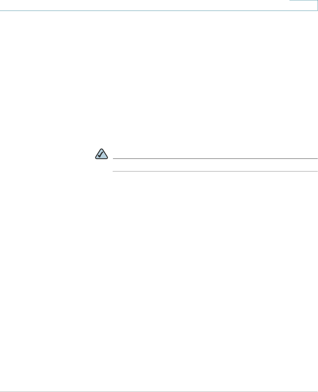
ISA570 and ISA570W Back Panel
281984
ANT02ANT01
RESET
I
/
O
POWER
12VDC
4
5
6
7
CONFIGURABLE
2
3
LAN
1
WAN
ANT01 ANT02
Reset
Button
Power
Switch
Power
Connector
WAN
Port
USB
Port Configurable
Ports
LAN
Ports
281981
I
/
O
RESET
ANT02ANT01
1
6
7
8910
WAN
CONFIGURABLE POWER
12VDC
2
3
4
5
LAN
ANT01 ANT02
Reset
Button
Power
Switch
Power
Connector
WAN
Port
USB
Port Configurable
Ports
LAN
Ports

Getting Started
Installation
Cisco ISA500 Series Integrated Security Appliance Administration Guide 18
1
Back Panel Descriptions
NOTE The back panel of ISA550 and ISA570 does not include two threaded connectors
for the antennas.
Installation
This section describes how to install the security appliance. It includes the
following topics:
•Before You Begin, page 19
Feature Description
ANT01/ANT02 Threaded connectors for the antennas (for ISA550W and
ISA570W only).
USB Port Connects the unit to a USB device. You can use a USB
device to backup and restore the configurations, or to
upgrade the firmware images.
Configurable
Ports
Can be set to operate as WAN, LAN, or DMZ ports. The
ISA550 and ISA550W have 4 configurable ports. The
ISA570 and ISA570W have 5 configurable ports.
LAN Ports Connects PCs and other network appliances to the unit.
The ISA550 and ISA550W have 2 dedicated LAN ports.
The ISA570 and ISA570W have 4 dedicated LAN ports.
WAN Port Connects the unit to a DSL or a cable modem, or another
WAN connectivity device.
RESET Button To reboot the unit, push and release the RESET button. To
restore the factory default settings, push and hold the
RESET button for 3 seconds.
Power Switch Turns the unit on or off.
Power
Connector
Connects the unit to power using the supplied power cord
and adapter.
Getting Started
Installation
Cisco ISA500 Series Integrated Security Appliance Administration Guide 19
1
•Installation Options, page 19
•Hardware Installation, page 22
Before You Begin
Before you begin the installation, make sure that you have the following
equipments and services:
•An active Internet account.
•Mounting kits and tools for installing the hardware. The kits packed with the
security appliance are used for desktop placement and rack mounting. The
kits include 4 rubber feet, 2 brackets, 2 silicon rubber spacers, 8 M3
screws, 4 M5 screws, and 4 washers.
NOTE The Wall-mounting kit is not included.
•RJ-45 Ethernet cables (Category 5 or higher) for connecting computers,
WAN and LAN interfaces, or other devices.
•A computer with Microsoft Internet Explorer 8.0, or Mozilla Firefox 3.6.x (or
later) for using the web-based Configuration Utility.
Installation Options
You can place your security appliance on a desktop, mount it on a wall, or mount it
in a rack. It includes the following topics:
•Placement Tips, page 19
•Wall Mounting, page 20
•Rack Mounting, page 21
Placement Tips
•Ambient Temperature: To prevent the security appliance from overheating,
do not operate it in an area that exceeds an ambient temperature of 104°F
(40°C).
•Air Flow: Be sure that there is adequate air flow around the device.
Getting Started
Installation
Cisco ISA500 Series Integrated Security Appliance Administration Guide 20
1
•Mechanical Loading: Be sure that the security appliance is level and stable
to avoid any hazardous conditions.
To place the security appliance on a desktop, install the supplied four rubber feet
on the bottom of the security appliance. Place the security appliance on a flat
surface.
Wall Mounting
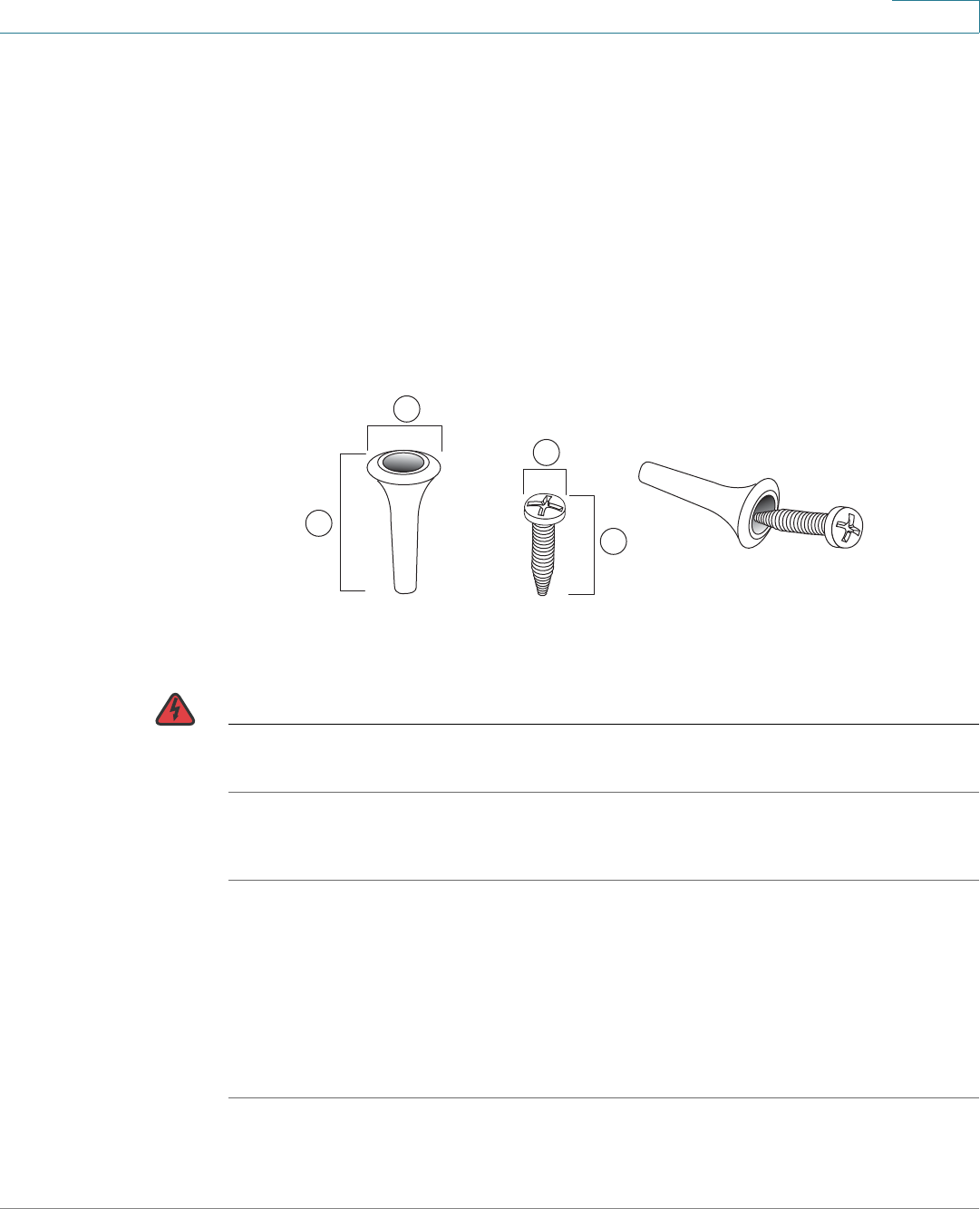
There is no wall-mounting kit included with your security appliance. We
recommend that you use the following screws to install your security appliance to
the wall or the ceiling:
WARNING Insecure mounting might damage the device or cause injury. Cisco is not
responsible for damages incurred by improper wall-mounting.
To mount the security appliance to the wall:
STEP 1 Determine where you want to mount the security appliance. Verify that the surface
is smooth, flat, dry, and sturdy.
STEP 2 Insert two 18.6 mm (0.73 inch) screws, with anchors, into the wall 234 mm apart
(9.21 inches). Leave 3 to 4 mm (about 1/8 inch) of the head exposed.
STEP 3 Place the security appliance wall-mount slots over the screws. Slide the security
appliance down until the screws fit snugly into the wall-mount slots.
1 8mm/0.32 in 2 25mm/0.98 in 3 6.5mm/0.26in 4 18.6mm/0.73in
1
2
4
3
196243
Getting Started
Installation
Cisco ISA500 Series Integrated Security Appliance Administration Guide 21
1
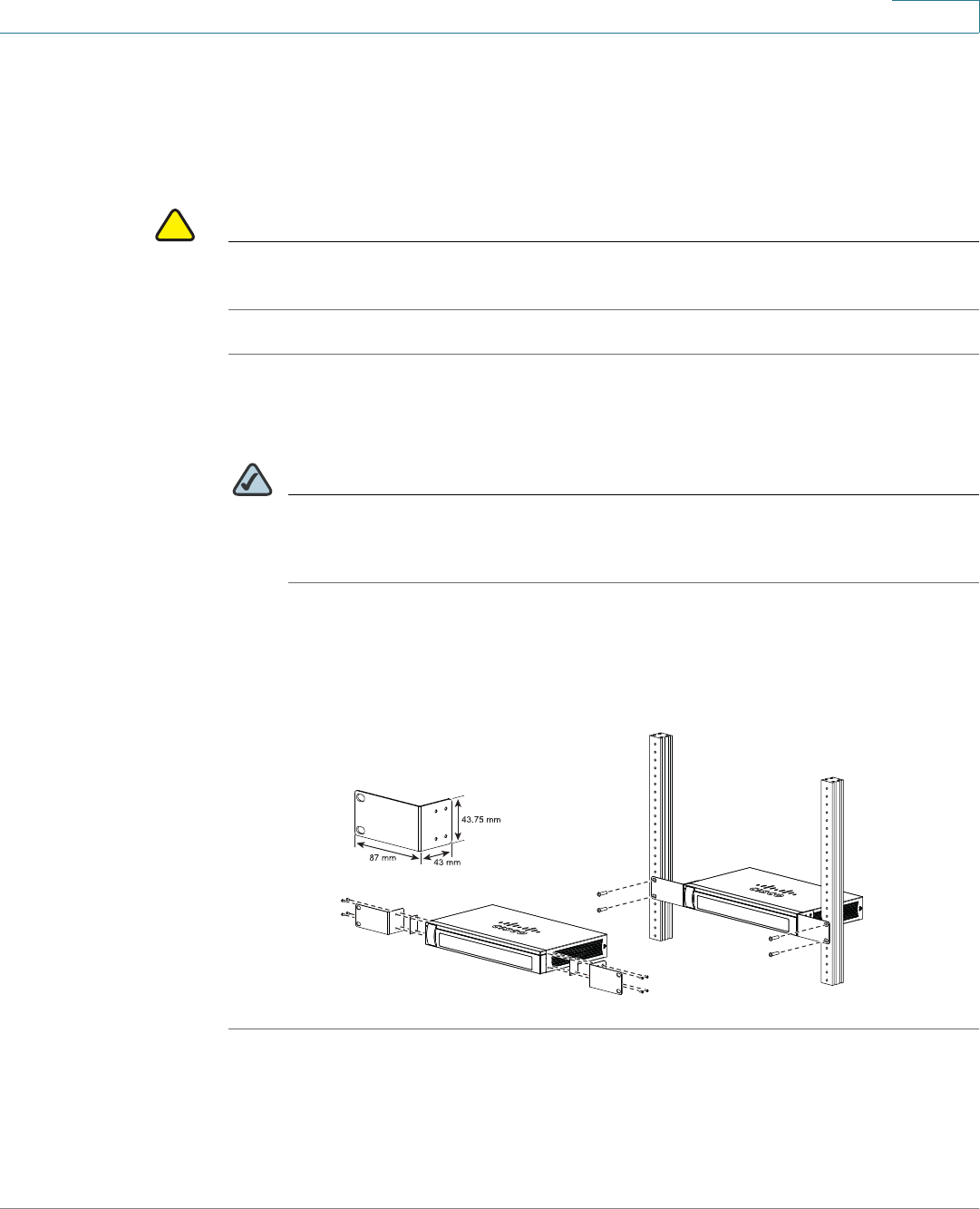
Rack Mounting
You can mount the security appliance in any standard size, 19-inch (about 48 cm)
wide rack. The security appliance requires 1 rack unit (RU) of space, which is 1.75
inches (44.45 mm) high.
!
CAUTION Do not overload the power outlet or circuit when installing multiple devices in a
rack.
STEP 1 Place one of the supplied silicon rubber spacers on the side of the security
appliance so that the four holes align to the screw holes. Place the rack mount
bracket next to the silicon rubber spacer and install the M3 screws.
NOTE If the M3 screws are not long enough to reattach the bracket with the silicon
rubber spacer, attach the bracket directly to the case without the silicon
rubber spacer.
STEP 2 Install the security appliance into a standard rack as shown below. Place the
washers on the brackets so that the holes align to the screw holes and then install
the M5 screws.
281985
Step 1 Step 2
Getting Started
Installation
Cisco ISA500 Series Integrated Security Appliance Administration Guide 22
1
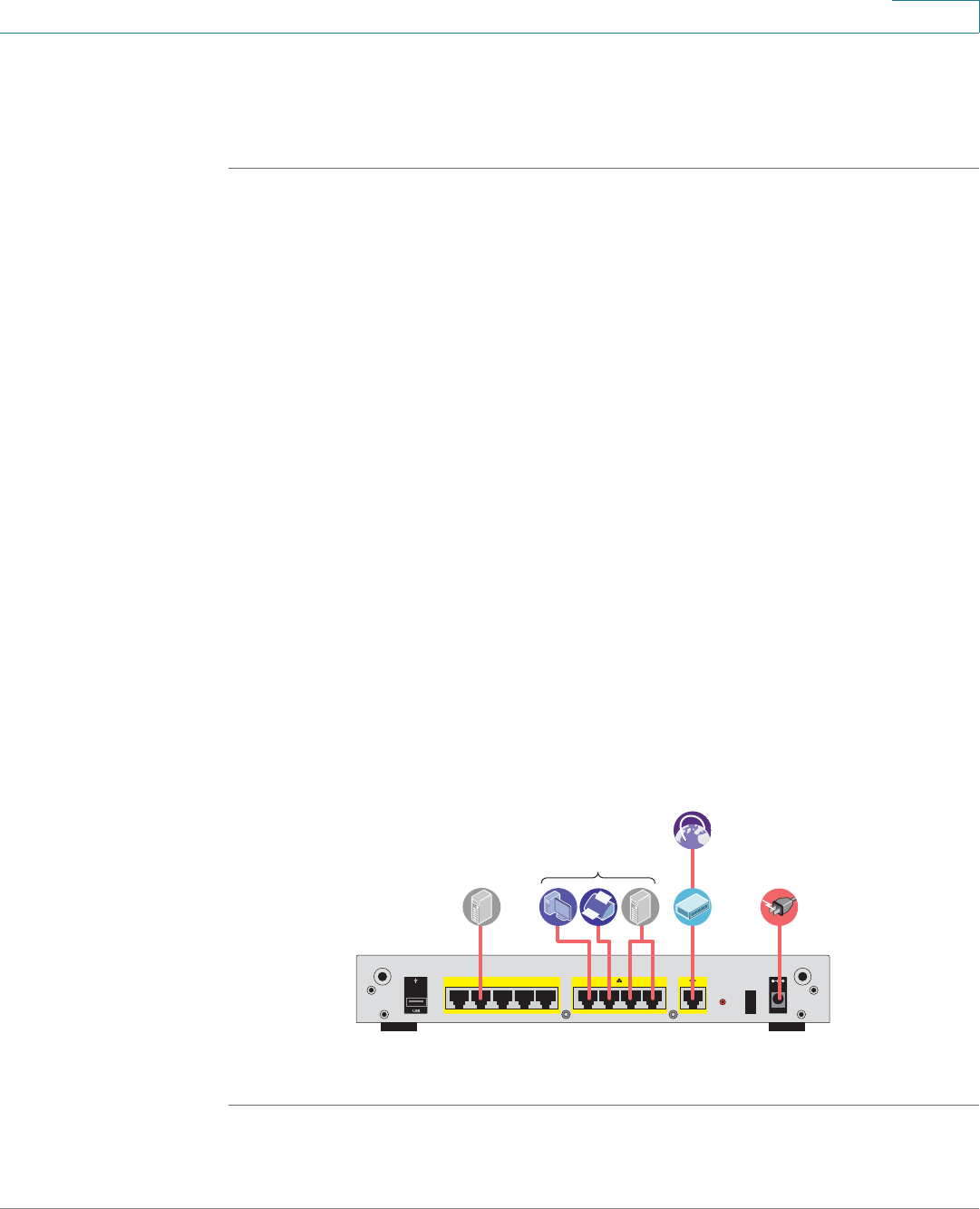
Hardware Installation
Follow these steps to connect the security appliance:
STEP 1 Connect the security appliance to power using the supplied power cord and
adapter. Make sure that the power switch is turned off.
STEP 2 If you are installing the ISA550W and ISA570W, screw each antenna onto a
threaded connector on the back panel. Orient each antenna to point upward.
STEP 3 For a DSL or cable modem, or other WAN connectivity devices, connect an
Ethernet network cable from the device to the WAN port on the back panel. Cisco
strongly recommends using Cat5E or better cable.
STEP 4 For network devices, connect an Ethernet network cable from the network device
to one of the dedicated LAN ports on the back panel.
STEP 5 For a UC 500 or a UC 300, connect an Ethernet network cable from the WAN port
of the UC 500 or a UC 300 to an available LAN port of the security appliance.
STEP 6 For a UC500 or a UC300, connect an Ethernet network cable from the WAN port of
the UC500 or UC300 to an available LAN port on the back panel of the security
appliance.
STEP 7 Power on the connected devices.
STEP 8 Power on the security appliance. The lights on the front panel for all connected
ports light up to show active connections.
A sample configuration is illustrated below.
Congratulations! The installation of the security appliance is complete.
281982
I
/
O
RESET
ANT02ANT01
1
6
7
8910
WAN
CONFIGURABLE POWER
12VDC
2
3
4
5
LAN
Internet
Access
Device
Public
Web Server Power
Network
Devices
Getting Started
Getting Started with the Configuration Utility
Cisco ISA500 Series Integrated Security Appliance Administration Guide 23
1
Getting Started with the Configuration Utility
The Configuration Utility is a web based device manager that is used to provision
the security appliance. To use this utility, you must be able to connect to the
security appliance from your administration PC or laptop. You can access the
security appliance by using web browser such as Microsoft Internet Explorer 8.0,
or Mozilla Firefox 3.6.x (or later). It includes the following sections:
•Launching the Configuration Utility, page 23
•Navigating Through the Configuration Utility, page 24
•Using the Help System, page 25
•Using the Management Buttons, page 25
Launching the Configuration Utility
STEP 1 Connect your computer to an available LAN port on the back panel of the security
appliance.
STEP 2 Start a web browser. In the Address bar, enter the default IP address of the
security appliance: 192.168.1.1.
NOTE The above address is the factory default LAN address. If you change this
setting in the DEFAULT VLAN configuration, you will need to enter the new IP
address to connect to the Configuration Utility.
STEP 3 Enter the default user name and password in the login screen:
•Username: cisco
•Password: cisco
STEP 4 Click Login.
For the first login, you are forced to immediately change the default user name and
password of the default administrator account to prevent unauthorized access.
For more information, see Changing the User Name and Password of the
Default Administrator Account at Your First Login, page 27.
Getting Started
Getting Started with the Configuration Utility
Cisco ISA500 Series Integrated Security Appliance Administration Guide 24
1
After you change them, the Startup Wizard launches. For more information about
how to use the Startup Wizard to configure your security appliance, see Using the
Startup Wizard, page 32.
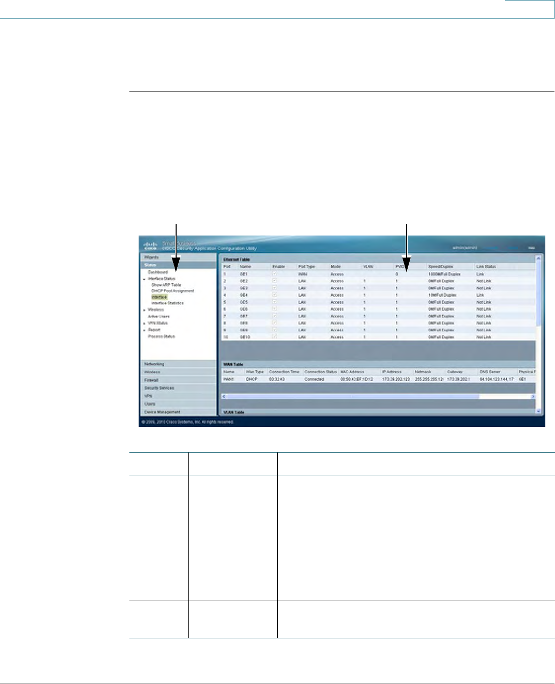
Navigating Through the Configuration Utility
Use the left hand navigation pane and content pane to perform the tasks in the
Configuration Utility.
12
Number Components Description
1Left Hand
Navigation
Pane
The left hand navigation pane provides easy
navigation through the configurable features. The
main branches expand to provide the features.
Click on the main branch title to expand its
contents. Click on the right arrow of a feature to
open its subfeatures, or click on the down arrow of
a feature to contract its subfeatures. Click on the
title of a feature or subfeature to open it.
2 Content Pane The content of the feature or subfeature appears in
this area.
Getting Started
About the Default Settings
Cisco ISA500 Series Integrated Security Appliance Administration Guide 25
1
Using the Help System
The Configuration Utility includes a detailed Help file for all configuration tasks. To
view the Help page, click the Help link in the top right corner of the screen.
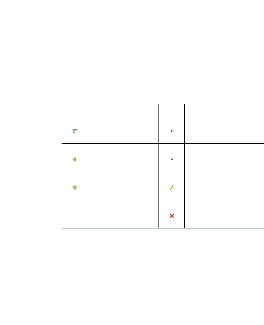
Using the Management Buttons
Device Management buttons and icons provide an easy method of configuring
device information. In this guide, we use the texts by replacing the buttons or icons
to indicate what the buttons or icons are used for.
About the Default Settings
The security appliance is predefined with the settings that allow you to start using
the device with minimal changes needed. Depending the requirements of your
Internet Service Provider (ISP) and the needs of your business, you might need to
modify some of these settings. You can use the Configuration Utility to customize
all settings, as needed.
Settings of particular interest are described below. For a full list of all factory
default settings, see Appendix C, "Factory Default Settings."
Icons Actions Icons Actions
Move Expand
Move Down Collapse
Move Up Edit or other specific actions
with relative description
Delete or Delete Selection

Getting Started
About the Default Settings
Cisco ISA500 Series Integrated Security Appliance Administration Guide 26
1
•IP Routing Mode: By default, only the IPv4 mode is enabled. To support the
IPv4 and IPv6 addressing, you need to enable the IPv4/IPv6 mode. To
change the IP routing mode, see Configuring IP Routing Mode, page 95.
•WAN Configuration: By default, the security appliance is configured to
obtain an IP address from your ISP by using Dynamic Host Configuration
Protocol (DHCP). Depending on the requirement of your ISP, you will need to
configure the network address mode for the primary WAN and the
secondary WAN if applicable. You can change other WAN settings as well.
See Configuring the WAN, page 101.
•LAN Configuration: By default, the LAN of the security appliance is
configured in the 192.168.1.0 subnet and the LAN IP address is 192.168.1.1.
The security appliance acts as a DHCP server to the hosts on the WLAN or
LAN network. It can automatically assign IP addresses and DNS server
addresses to the PCs and other devices on the LAN. For most deployment
scenarios, the default DHCP and TCP/IP settings should be satisfactory.
However, you can change the subnet address or the default IP address. You
can assign static IP addresses to connected devices rather than allowing the
security appliance to act as a DHCP server. See Configuring the VLAN,
page 118.
•VLAN Configuration: The security appliance predefines a native VLAN
(DEFAULT) and a guest VLAN (GUEST). You can customize new VLANs for
your specific business needs. See Configuring the VLAN, page 118.
•Configurable Ports: By default, all configurable ports are set to act as LAN
ports. Alternatively, you can configure the configurable port for use as a DMZ
port or a secondary WAN port. See Configuring the WAN, page 101 or
Configuring the DMZ, page 123.
•Wireless Network (for ISA550W and ISA570W only): The ISA550W or
ISA570W is configured with four SSIDs. All SSIDs are disabled by default.
For security purposes, we strongly recommend that you configure the SSIDs
with the appropriate security settings. See Wireless Configuration for
ISA550W and ISA570W, page 157.
•Administrative Access: You can access the Configuration Utility by using a
web browser and entering the default LAN IP address of 192.168.1.1. You
can log into by entering the username and password of the default
administrator account. You are forced to change the default username and
password after the first login. See Changing the User Name and Password
of the Default Administrator Account at Your First Login, page 27. You
also may want to change the user login settings for authentication. See
Configuring the User Authentication Settings, page 277.

Getting Started
Performing Common Configuration Tasks
Cisco ISA500 Series Integrated Security Appliance Administration Guide 27
1
•Security Services: By default, the UTM security services such as Intrusion
Prevention Service (IPS), Web URL Filter, Web Reputation Filter, Anti-Virus,
and Email Reputation Filter are disabled. For more information about how to
configure the security services, see Security Services, page 210.
•Firewall: By default, the firewall prevents inbound traffic and allows all
outbound traffic. If you want to allow some inbound traffic or prevent some
outbound traffic, you must customize firewall access rules. The security
appliance supports up to 100 custom access rules. See Configuring the
Firewall Access Rules to Control Inbound and Outbound Traffic,
page 178.
•VPN: By default, the VPN feature is disabled. The security appliance can
function as a Cisco IPSec VPN server or a Cisco VPN hardware client, or as
a SSL VPN gateway so that remote users can securely access the corporate
network resources over the VPN tunnels. You can also establish a secure
IPSec VPN tunnel between two sites that are physically separated by using
the Site-to-Site VPN feature. For more information about how to configure the
VPN features, see VPN, page 232.
Performing Common Configuration Tasks
We strongly recommend that you complete the following common tasks before
you begin configuring your security appliance. It includes the following sections:
•Changing the User Name and Password of the Default Administrator
Account at Your First Login, page 27
•Saving Your Configuration, page 28
•Upgrading the Firmware if needed, page 29
•Resetting the Device, page 30
Changing the User Name and Password of the Default
Administrator Account at Your First Login
The default administrator account is an administrative account that has fully
privilege to set the configurations and read the system status. It does not belong to
any user group. To prevent unauthorized access, you are forced to immediately
change the default user name and password at its first login.
Getting Started
Performing Common Configuration Tasks
Cisco ISA500 Series Integrated Security Appliance Administration Guide 28
1
STEP 1 After the first login, a prompt window opens.
STEP 2 Enter the following information:
•User Name: Enter a new user name that contains the letters, numbers, or
underline for the default administrator account.
•New Password: Enter a new password for the default administrator account.
Passwords are case-sensitive.
NOTE Restrictions for password: The password should contain at least
three types of these character classes: lower case letters, upper case
letters, numbers, and special characters. Do not repeat any character
more than three times consecutively. Do not set the password as the
user name or the reversed user name. The password cannot be set as
“cisco”, “ocsic”, or any variant obtained by changing the capitalization
of letters.
•Confirm Password: Enter the new password again for confirmation.
STEP 3 Click Save to apply your settings.
Saving Your Configuration
At any point during the configuration process, you can save your configurations.
Later, if you make changes that you want to abandon, you can easily revert to the
saved configurations.
STEP 1 Click Device Management -> Firmware and Configuration -> Configuration.
The Configuration window opens.
STEP 2 To save the current settings on your local PC, perform the following steps:
a. In Backup/Restore Settings area, click Backup after the Save A Copy of
Current Settings option.
b. The Encryption window opens. You can optionally encrypt the configurations
for security purposes, check the Encrypt box and enter the password in the
Key field, and then click OK.
Getting Started
Performing Common Configuration Tasks
Cisco ISA500 Series Integrated Security Appliance Administration Guide 29
1
c. Locate where to save the configuration file, and then click Save.
STEP 3 To save the current settings on a USB device, perform the following steps:
a. Insert a USB device into the USB interface on the back panel of your security
appliance. The USB device is automatically mounted once you insert it.
b. In the USB -> Mount/Unmount area, check the mounting status of the USB
device. Make sure that the USB Driver Status shows as “UP” when you use the
USB device to manage the configurations.
c. In the USB -> Backup/Restore Settings area, click Backup after the Save A
Copy of Current Settings option.
d. The Encryption window opens. You can optionally encrypt the configurations
for security purposes, check the Encrypt box and then enter the password in
the Key field, and then click OK. Your current settings are saved as a
configuration file on the root folder of the USB device.
Upgrading the Firmware if needed
Before you do any other tasks, ensure that you are using the latest firmware
version. You can upgrade from a firmware file stored on your computer or a
mounted USB device.
!
CAUTION During a firmware upgrade, do NOT try to go online, turn off the device, shut down
the PC, remove the cable, or interrupt the process in anyway until the operation is
complete. This process should take several minutes or so including the reboot
process. Interrupting the upgrade process at specific points when the flash is
being written to can corrupt the flash memory and render the security appliance
unusable.
STEP 1 Click Device Management -> Firmware and Configuration -> Firmware.
The Firmware window opens.

Getting Started
Performing Common Configuration Tasks
Cisco ISA500 Series Integrated Security Appliance Administration Guide 30
1
STEP 2 To manually upgrade the firmware from your local PC, perform the following steps:
a. In the Network -> Firmware Upgrade area, click Browse to locate and select
the firmware image from your local PC.
b. To upgrade the firmware and keep using the current settings, click Upgrade.
c. To upgrade the firmware and revert to the factory default settings, click
Upgrade & Factory Reset. When the operation is complete, the security
appliance automatically reboots with the factory default settings.
STEP 3 To upgrade the firmware through a USB device, perform the following steps:
a. Insert the USB device with the firmware images into the USB interface on the
back panel of your security appliance. The USB device is automatically
mounted after you inserted it.
b. In the USB -> Mount/Unmount area, check the mounting status of the USB
device. Make sure that the USB Driver Status shows as “UP” when you use the
USB device to manage the firmware.
c. In the USB -> Backup/Restore Settings area, all firmware images located on
the USB device appears in the list.
•To upgrade the firmware and keep using the current settings, select the
latest firmware image from the list and then click Upgrade.
•To upgrade the firmware and revert to the factory default settings, select the
latest firmware image from the list and then click Upgrade & Factory Reset.
When the operation is complete, the security appliance automatically
reboots with the factory default settings.
Resetting the Device
To revert your security appliance to the factory default settings, you can press and
hold the RESET button on the back panel for minimum of 3 seconds, or perform the
following procedures.
!
CAUTION The Revert To Factory Default Settings operation will wipe out the current
configurations used on your security appliance (including the imported
certificates). We recommmend that you save the current settings before reverting
to the factory default settings.

Getting Started
Performing Common Configuration Tasks
Cisco ISA500 Series Integrated Security Appliance Administration Guide 31
1
STEP 1 Click Device Management -> Firmware and Configuration -> Configuration.
The Configuration window opens.
STEP 2 In the Backup/Restore Settings -> Revert To Factory Default Settings area,
click Default.
The security appliance will reboot with the factory default settings.

2
Cisco ISA500 Series Integrated Security Appliance Administrator Guide 32
Wizards
This chapter describes how to use the wizards to configure your security
appliance.
•Using the Startup Wizard, page 32
•Using the Wireless Wizard to Configure the Wireless Settings for
ISA550W and ISA570W, page 40
•Using the DMZ Wizard to Configure the DMZ Settings, page 46
•Using the Dual WAN Wizard to Configure the WAN Redundancy
Settings, page 51
•Using the Site-to-Site Wizard to Establish the Site-to-Site VPN Tunnels,
page 53
•Using the Remote Access Wizard to Establish the IPSec VPN Tunnels or
SSL VPN Tunnels for Remote Access, page 58
To access the Wizards pages, click Wizards in the left hand navigation pane.
Using the Startup Wizard
The Startup Wizard helps you configure the remote management, port, WAN, LAN,
DMZ, and WLAN (for ISA550W and ISA570W only) settings. The first time you log
into your security appliance, the Startup Wizard automatically launches.
STEP 1 Click Wizard -> Startup Wizard.
The Getting Started window opens. A prompt warning message is displayed as
below.

Wizards
Using the Startup Wizard
Cisco ISA500 Series Integrated Security Appliance Administrator Guide 33
2
!
CAUTION When the Startup Wizard is complete, the previous settings relevant to the
changed WAN, DDNS, LAN, DMZ, and WLAN are cleaned up, and relevant services
are reinitialized.
For the first login, you can ignore this warning message and follow the on-screen
prompts to complete the initial configuration. If you have already configured the
security appliance, make sure that you have read the warning message before you
use the Startup Wizard to configure your security appliance. Click OK to close the
warning message window.
STEP 2 Click Begin.
The Remote Management window opens. The security appliance allows remote
management securely by using HTTPS and HTTP. For example, https://
xxx.xxx.xxx.xxx:8080.
Enter the following information:
•Remote Management: Click On to enable remote management by using
HTTPS, or click Off to disable it. We recommend that you use HTTPS for
secure purposes.
•HTTPS Listen Port Number: If you enable remote management by using
HTTPS, enter the port number to be listened on. By default, the listened port
for HTTPS is 8080.
•HTTP Enable: Click On box to enable remote management by using HTTP,
or click Off to disable it.
•HTTP Listen Port Number: If you enable remote management by using
HTTP, enter the port number to be listened on. By default, the listened port
for HTTP is 80.
•Access Type: Choose the level of permission for remote management:
-Allow access from any IP address: Any IP address from a remote WAN
network can access the Configuration Utility.
-Restrict a specific IP address: Only the specified remote host can
access the Configuration Utility. Enter the IP address of the remote host
in the IP Address field.

Wizards
Using the Startup Wizard
Cisco ISA500 Series Integrated Security Appliance Administrator Guide 34
2
-Restrict access to a range of IP addresses: Only the hosts in the
specified remote network can access the Configuration Utility. Enter the
starting IP address in the From field and the ending IP address in the To
field.
•Remote SNMP: Click On to enable SNMP for the remote connection, or click
Off to disable SNMP. Enabling SNMP allows remote users to use the SNMP
protocol to access the Configuration Utility.
STEP 3 After you are finished, click Next.
The Port Configuration window opens. From this page you can specify the port
configuration. The Startup Wizard predefines four port configuration solutions. You
can also modify the port types for the configurable ports when you create a
secondary WAN or configure the DMZs.
If you are using the ISA570 or ISA570W, choose one of the following options:
•1 WAN, 9 LAN Switch: This is the default setting. The security appliance is
set to one WAN port (WAN1) and nine LAN ports.
•1 WAN, 1 DMZ, and 8 LAN Switch: The security appliance is set to one
WAN port (WAN1), one DMZ port, and eight LAN ports. The configurable port
GE10 is set to a DMZ port.
•1 WAN, 1 WAN Backup, and 8 LAN Switch: The security appliance is set to
two WAN ports (WAN1 is the primary WAN and WAN2 is the secondary
WAN) and eight LAN ports. The configurable port GE10 is set to a secondary
WAN port.
•1 WAN, 1 WAN Backup, 1 DMZ, and 7 LAN Switch: The security appliance
is set to two WAN ports (WAN1 is the primary WAN and WAN2 is the
secondary WAN), one DMZ port, and seven LAN ports. The configurable
port GE10 is set to a secondary WAN port and the configurable port GE9 is
set to a DMZ port.
If you are using the ISA550 or ISA550W, choose one of the following options:
•1 WAN, 6 LAN Switch: This is the default setting. The security appliance is
set to one WAN port (WAN1) and six LAN ports.
•1 WAN, 1 DMZ, and 5 LAN Switch: The security appliance is set to one
WAN port (WAN1), one DMZ port, and five LAN ports. The configurable port
GE7 is set to a DMZ port.
Wizards
Using the Startup Wizard
Cisco ISA500 Series Integrated Security Appliance Administrator Guide 35
2
•1 WAN, 1 WAN Backup, and 5 LAN Switch: The security appliance is set to
two WAN ports (WAN1 is the primary WAN and WAN2 is the secondary
WAN) and five LAN ports. The configurable port GE7 is set to a secondary
WAN port.
•1 WAN, 1 WAN Backup, 1 DMZ, and 4 LAN Switch: The security appliance
is set to two WAN ports (WAN1 is the primary WAN and WAN2 is the
secondary WAN), one DMZ port, and four LAN ports. The configurable port
GE7 is set to a secondary WAN port and the configurable port GE6 is set to
a DMZ port.
NOTE If you have two ISP links, we recommend that you set a backup WAN
so that you can provide backup connectivity or load balancing. If you
need to host public services, we recommend that you set a DMZ port.
NOTE The configurable ports can be set as the WAN, LAN, and DMZ ports.
Up to two WAN ports and four DMZ ports can be configured on the
security appliance. To configure multiple DMZ ports, go to the
Networking -> DMZ page. For more information, see Configuring the
DMZ, page 123.
STEP 4 After you are finished, click Next.
The Primary WAN Connection window opens. From this page you can configure
the primary WAN port.
Choose the network addressing mode from the IP Address Assignment drop-
down list and complete the corresponding fields for the primary WAN port
depending on the requirements of your ISP. The security appliance supports
DHCPC, Static IP, PPPoE, PPTP, and L2TP. For complete details, see Configuring
the Network Addressing Mode, page 106.
NOTE If only one single WAN port is configured on your security appliance, skip the
next two steps and proceed to the step 7.
STEP 5 After you are finished, click Next.
The Secondary WAN Connection window opens. From this page you can
configure the secondary WAN port.

Wizards
Using the Startup Wizard
Cisco ISA500 Series Integrated Security Appliance Administrator Guide 36
2
Choose the network addressing mode from the IP Address Assignment drop-
down list and complete the corresponding fields for the secondary WAN port
depending on the requirements of your ISP. For complete details, see Configuring
the Network Addressing Mode, page 106.
STEP 6 After you are finished, click Next.
The WAN Redundancy window opens. From this page you can determine how the
two ISP links are used.
•Use the Loab Balancing mode if you want to use both ISP links
simultaneously. The two links will carry data for the protocols that are bound
to them. Enter the following information:
-Equal Load Balancing (Round Robin): Re-orders the WAN interfaces for
Round Robin selection. The order is as follows: WAN1 and WAN2. The
Round Robin will then repeat back to WAN1 and continue the order.
-Weighted Load Balancing: Distributes the bandwidth to two WAN ports
by the weighted percange or by the weighted link bandwidth. If you
choose this mode, then choose one of the following options and finish the
setting:
Weighted By percentage: Allows you to set the percentage for each
WAN, such as 80% percentage bandwidth for WAN1 and lest 20%
percentage bandwidth for WAN2.
Weighted By Link Bandwidth: Allows you to set the rate limiting for each
WAN, such as 10 Mbps for WAN1 and 5 Mbps for WAN2.
•Use the Failover mode if you want to use one ISP link as a backup. If a failure
is detected on the primary link, then the security appliance directs all
Internet traffic to the backup link. When the primary link regains connectivity,
all Internet traffic is directed to the primary link, and the backup link becomes
idle. Enter the following information:
-Auto Failover to: Choose either WAN1 or WAN2 as the primary link. By
default, WAN1 is set as the primary link and WAN2 is set as the backup
link. You can also set WAN2 as the primary link.
-Preempt Delay Timer: Enter the time in seconds that the system will
preempt the primary link from the backup link when the primary link is up
again. The default is 5 seconds.
STEP 7 After you are finished, click Next.
The LAN Configuration window opens. From this page you can configure the
default LAN settings.
Wizards
Using the Startup Wizard
Cisco ISA500 Series Integrated Security Appliance Administrator Guide 37
2
•IP: Enter the IP address of the default LAN.
•Netmask: Enter the IP address of the netmask.
•DHCP Server: Choose one of the following DHCP modes:
-Disable: Choose this option if the computers on the VLAN are configured
with static IP addresses or are configured to use another DHCP server.
-DHCP Server: Allows the security appliance to act as a DHCP server and
assigns IP addresses to all devices that are connected to the DEFAULT
VLAN. Any new DHCP client joining the DEFAULT VLAN is assigned an IP
address of the DHCP pool.
-DHCP Relay: Allows the security appliance to use a DHCP Relay. If you
choose DHCP Relay, enter the IP address of the remote DHCP server in
the Relay IP field.
If you choose DHCP Server as the DHCP mode, enter the following information:
•Start IP: Enter the starting IP address of the DHCP pool.
•End IP: Enter the ending IP address of the DHCP pool.
NOTE The starting and ending IP addresses should be in the same range as
the LAN’s subnet address.
•Lease Time: Enter the maximum connection time that a dynamic IP address
is “leased” to a network user. When the time elapses, the user is
automatically renewed the dynamic IP address.
•DNS 1: Enter the IP address of the primary DNS server.
•DNS 2: Optionally, enter the IP address of the secondary DNS server.
•WINS 1: Enter the IP address for the primary WINS server.
•WINS 2: Optionally, enter the IP address of the secondary WINS server.
•Domain Name: Optionally, enter the domain name for the default LAN.
•Default Gateway: Enter the IP address of default gateway.
STEP 8 After you are finished, click Next.
If you have no DMZ port, skip the next two steps and proceed to the step 10.
Wizards
Using the Startup Wizard
Cisco ISA500 Series Integrated Security Appliance Administrator Guide 38
2
If you have a DMZ port, the DMZ Configuration window opens. To host public
services, you need to configure a DMZ network in this page and specify the
relevant DMZ services from the next DMZ Service page.
•IP: Enter the subnet IP address of the DMZ.
•Netmask: Enter the subnet mask of the DMZ.
•DHCP Service: Choose one of the following options:
-Disable: Choose this option if the computers on the DMZ are configured
with static IP addresses or are configured to use another DHCP server.
-DHCP Server: Allows the security appliance to act as a DHCP server and
assigns IP addresses to all devices that are connected to the DMZ. Any
new DHCP client joining the DMZ is assigned an IP address of the DHCP
pool.
-DHCP Relay: Allows the security appliance to use a DHCP Relay. If you
choose DHCP Relay, enter the IP address of the remote DHCP server in
the Relay IP field.
If you choose DHCP Server as the DHCP mode, enter the following information:
•Start IP: Enter the starting IP address of the DHCP pool.
•End IP: Enter the ending IP address of the DHCP pool.
NOTE The starting and ending IP addresses should be in the same range as
the DMZ’s subnet address.
•Lease Time: Enter the maximum connection time that a dynamic IP address
is “leased” to a network user. When the time elapses, the user is
automatically renewed the dynamic IP address.
•DNS 1: Enter the IP address of the primary DNS server.
•DNS 2: Optionally, enter the IP address of the secondary DNS server.
•WINS 1: Enter the IP address for the primary WINS server.
•WINS 2: Optionally, enter the IP address of the secondary WINS server.
•Domain Name: Optionally, enter the domain name for the DMZ.
•Default Gateway: Enter the IP address of default gateway.
Wizards
Using the Startup Wizard
Cisco ISA500 Series Integrated Security Appliance Administrator Guide 39
2
STEP 9 After you are finished, click Next.
The DMZ Service window opens. From this page you can configure the DMZ
services. For complete details, see Configuring the DMZ Services, page 49.
NOTE After you configure the DMZ services, the firewall access rules will
automatically generated by the security appliance to allow the access to the
services on your DMZ.
STEP 10 After you are finished, click Next.
The Wireless Radio Setting window opens. From this page you can configure the
wireless radio settings.
NOTE The wireless configurations such as wireless radio settings and Intranet
WLAN access (see next step) are only available for the ISA550W and
ISA570W. If your security appliance is not a wireless device, proceed to the
step 12.
•Wireless Network Mode: Choose the 802.11 modulation technique. The
ISA550W and ISA550W supports the following radio modes:
-802.11b only: Choose this mode if all devices in the wireless network
use 802.11b. Only 802.11b clients can connect to the access point.
-802.11g only: Choose this mode if all devices in the wireless network
use 802.11g. Only 802.11g clients can connect to the access point.
-802.11b/g mixed: Choose this mode if some devices in the wireless
network use 802.11b and others use 802.11g. Both 802.11b and 802.11g
clients can connect to the access point.
-802.11n only: Choose this mode if all devices in the wireless network
can support 802.11n. Only 802.11n clients operating in the 2.4 GHz
frequency can connect to the access point.
-802.11g/n mixed: Choose this mode to allow 802.11g and 802.11n
clients operating in the 2.4 GHz frequency to connect to the access point.
-802.11b/g/n mixed: Choose this mode to allow 802.11b, 802.11g, and
802.11n clients operating in the 2.4 GHz frequency to connect to the
access point.
Wizards
Using the Wireless Wizard to Configure the Wireless Settings for ISA550W and ISA570W
Cisco ISA500 Series Integrated Security Appliance Administrator Guide 40
2
•Wireless Channel: Choose a channel or choose Auto to let the system
determine the best channel to use based on the environmental noise levels
for the available channels.
STEP 11 After you are finished, click Next.
The Wireless Connectivity Type - Intranet WLAN Access window opens. From this
page you can configure the wireless connectivity settings for the SSID1.
NOTE The ISA550W and ISA570W support four SSIDs. To configure the wireless
connectivity settings for other SSIDs, go to the Wireless -> Basic Settings
page or use the Wireless wizard. For more information, see Configuring the
Access Points, page 151 or Using the Wireless Wizard to Configure the
Wireless Settings for ISA550W and ISA570W, page 40.
•SSID Name: The SSID name.
•Security Mode: Choose the encryption algorithm for data encryption for this
SSID. Depending on the selected security mode, configure the
corresponding settings. See Configuring the Security Mode, page 162.
•VLAN Name: Choose the VLAN to which this SSID is mapped. All traffic from
the wireless clients that are connected to this SSID will be directed to the
selected VLAN.
STEP 12 After you are finished, click Next.
The Summary window opens. The Summary page displays the summary
information for all configurations you made.
STEP 13 Click Submit to save the settings.
Using the Wireless Wizard to Configure the Wireless Settings
for ISA550W and ISA570W
Use the Wireless Wizard to configure the wireless radio and Intranet connectivity
settings for the ISA550W and ISA570W. It includes the following sections:
•Using the Wireless Wizard to Configure the Wireless Settings, page 41

Wizards
Using the Wireless Wizard to Configure the Wireless Settings for ISA550W and ISA570W
Cisco ISA500 Series Integrated Security Appliance Administrator Guide 41
2
•Configuring the SSID for Intranet WLAN Access, page 43
•Configuring the SSID for Guest WLAN Access, page 44
•Configuring the SSID for Guest WLAN Access (Captive Portal), page 45
Using the Wireless Wizard to Configure the Wireless Settings
STEP 1 Click Wizards -> Wireless Wizard.
The Getting Started window opens.
STEP 2 Click Begin.
The Wireless Radio Setting window opens. Enter the following information:
•Wireless Network Mode: Specify the Physical Layer (PHY) standard that
the wireless radio uses.
-802.11b only: Choose this mode if all devices in the wireless network
use 802.11b. Only 802.11b clients can connect to the access point.
-802.11g only: Choose this mode if all devices in the wireless network
use 802.11g. Only 802.11g clients can connect to the access point.
-802.11b/g mixed: Choose this mode if some devices in the wireless
network use 802.11b and others use 802.11g. Both 802.11b and 802.11g
clients can connect to the access point.
-802.11n only: Choose this mode if all devices in the wireless network
can support 802.11n. Only 802.11n clients operating in the 2.4 GHz
frequency can connect to the access point.
-802.11g/n mixed: Choose this mode to allow 802.11g and 802.11n
clients operating in the 2.4 GHz frequency to connect to the access point.
-802.11b/g/n mixed: Choose this mode to allow 802.11b, 802.11g, and
802.11n clients operating in the 2.4 GHz frequency to connect to the
access point.
•Wireless Channel: Choose a channel or choose Auto to let the system
determine the best channel to use based on the environmental noise levels
for the available channels.
STEP 3 After you are finished, click Next.
The Choose SSIDs window opens. From this page you can enable the SSIDs and
choose the wireless connectivity type for each active SSID.
Wizards
Using the Wireless Wizard to Configure the Wireless Settings for ISA550W and ISA570W
Cisco ISA500 Series Integrated Security Appliance Administrator Guide 42
2
•Enable: Check this box to enable the SSID.
•Mode: Choose the wireless connectivity type for each enabled SSID.
-Intranet WLAN Access: Allows wireless users to access the corporate
network via the wireless network. The WLAN is mapped to the DEFAULT
VLAN.
-Guest WLAN Access: Only allows guest users to access the corporate
network via the wireless network. The WLAN is mapped to the GUEST
VLAN.
-Guest WLAN Access (Captive Portal): Only allows guest users who
authenticated successfully to access the corporate network via the
wireless network. The wireless users will be directed to a specific web
authentication login page to authenticate, and then be directed to a
specified web portal after login successfully before they can access the
Internet.
NOTE Only one SSID can be set for Guest WLAN access and Captive Portal
WLAN access.
STEP 4 Specify the wireless connectivity settings for all enabled SSIDs.
Depending on the wireless connectivity type that you selected for the SSID, you
need to complete the relevant settings for each enabled SSID.
For complete details to configure the Intranet WLAN access, see Configuring the
SSID for Intranet WLAN Access, page 43.
For complete details to configure the Guest WLAN access, see Configuring the
SSID for Guest WLAN Access, page 44.
For complete details to configure the Captive Portal WLAN access, see
Configuring the SSID for Guest WLAN Access (Captive Portal), page 45.
STEP 5 After you are finished, click Next.
The Summary window opens. The Summary page displays the summary
information for all configurations you made for the SSIDs.
STEP 6 Click Submit to save your settings and exit the Wireless Wizard.

Wizards
Using the Wireless Wizard to Configure the Wireless Settings for ISA550W and ISA570W
Cisco ISA500 Series Integrated Security Appliance Administrator Guide 43
2
Configuring the SSID for Intranet WLAN Access
This section describes how to configure the connectivity settings for Intranet
WLAN access.
STEP 1 After you enable the SSIDs and specify the wireless connectivity type for each
SSID, click Next.
If SSID1 is enabled and is set to Intranet WLAN Access, the SSID1 window opens.
STEP 2 Enter the following information:
•SSID: Enter the SSID name.
•Broadcast SSID: Check the box to broadcast the SSID in its beacon frames.
All wireless devices within range are able to see the SSID when they scan
for available networks. Uncheck the box to prevent auto-detection of the
SSID. In this case, users must know the SSID to set up a wireless connection
to this SSID.
•PC Visibility: Check the box so that the wireless clients on the same SSID
will be able to see eachother.
STEP 3 In the Security Settings area, specify the wireless security settings.
•Security Mode: Choose the security mode and configure the
correspoinding information. For security purposes, Cisco strongly
recommends WPA2 for wireless security. For example, if you choose WPA2-
Personal, enter the following information:
-Encryption: WPA2-Personal always uses AES for data encryption.
-Shared Secret: The Pre-shared Key (PSK ) is the shared secret key for
WPA. Enter a string of at least 8 characters to a maximum of 63
characters.
-Key Renewal Timeout: Enter a value to set the interval at which the key
is refreshed for clients associated to this SSID. A value of 0 indicates that
the key is not refreshed. The default is 3600 seconds.
NOTE For complete details for other security modes, see Configuring the
Security Mode, page 162.
STEP 4 In the Advanced Settings area, enter the following information:

Wizards
Using the Wireless Wizard to Configure the Wireless Settings for ISA550W and ISA570W
Cisco ISA500 Series Integrated Security Appliance Administrator Guide 44
2
•VLAN Mapping: Choose the VLAN to which the SSID is mapped. All traffic
from the wireless clients that are connected to this SSID will be directed to
the selected VLAN. For Intranet VLAN access, you should choose a VLAN
that is mapped to a trust zone.
•User Limit: Specify the maximum number of users that can simultaneously
connect to this SSID.
Configuring the SSID for Guest WLAN Access
This section describes how to configure the connectivity settings for Guest WLAN
access.
STEP 1 After you are finished the SSID1 configuration, click Next.
If SSID2 is enabled and is set to Guest WLAN Access, the SSID2 window opens.
STEP 2 Enter the following information:
•SSID: Enter the SSID name.
•Broadcast SSID: Check the box to broadcast the SSID in its beacon frames.
All wireless devices within range are able to see the SSID when they scan
for available networks. Uncheck the box to prevent auto-detection of the
SSID. In this case, users must know the SSID to set up a wireless connection
to this SSID.
•PC Visibility: Check the box so that the wireless clients on the same SSID
are able to see eachother.
STEP 3 In the Security Settings area, specify the wireless security settings.
•Security Mode: Choose the security mode and configure the
correspoinding information. For the complete details for how to configure the
security modes, see Configuring the Security Mode, page 162.
STEP 4 In the Advanced Settings area, enter the following information:
•VLAN Mapping: Choose the VLAN to which the SSID is mapped. All traffic
from the wireless clients that are connected to this SSID will be directed to
the selected VLAN. For Guest VLAN access, you should choose a VLAN that
is mapped to a guest zone.

Wizards
Using the Wireless Wizard to Configure the Wireless Settings for ISA550W and ISA570W
Cisco ISA500 Series Integrated Security Appliance Administrator Guide 45
2
•User Limit: Specify the maximum number of users that can simultaneously
connect to this SSID.
Configuring the SSID for Guest WLAN Access (Captive Portal)
This section describes how to configure the connectivity settings for Captive
Portal WLAN access.
STEP 1 After you are finished the SSID2 configuration, click Next.
If SSID3 is enabled and is set to Guest WLAN Access (Captive Portal), the SSID3
window opens.
STEP 2 Enter the following information:
•SSID: Enter the SSID name.
•Broadcast SSID: Check the box to broadcast the SSID in its beacon frames.
All wireless devices within range are able to see the SSID when they scan
for available networks. Uncheck the box to prevent auto-detection of the
SSID. In this case, users must know the SSID to set up a wireless connection
to this SSID.
•PC Visibility: Check the box so that the wireless clients on the same SSID
are able to see eachother.
STEP 3 In the Security Settings area, specify the wireless security settings.
•Security Mode: Choose the security mode and configure the
correspoinding information. For the complete details for how to configure the
security modes, see Configuring the Security Mode, page 162.
STEP 4 In the Captive Portal WLAN Access -> Autentication area, enter the following
information:
•Autentication Method: The authentication method that is used to
authenticate the wireless users. This setting is derived from the user login
settings. Go to the Users -> Settings page to set the authentication method.
For more information, see Configuring the User Authentication Settings,
page 277.
STEP 5 In the Captive Portal WLAN Access -> Captive Portal Authentication Type area,
specify the web authentication type and configure the relevant settings:
•Web Authentication Type: Choose one of the following methods:

Wizards
Using the DMZ Wizard to Configure the DMZ Settings
Cisco ISA500 Series Integrated Security Appliance Administrator Guide 46
2
-Internal: Allows you to use the default web authentication login page to
authenticate the wireless users. If you choose this option, enter the URL
of the portal in the Redirect URL After Login field and specify the
monitored HTTP port list. If you do not specify the portal, the wireless
user can access the original web site directly.
-External Web Server: Allows you to use a customized web
authentication login page on an external web server to authenticate the
wireless users. If you choose this option, enter the IP address of the
external web server in the Authentication Web Server field and the key
in the Authentiation Web Key field. The authentication web key is used
to protect the user name and password that the external web server
sends to your security appliance for authentication.
For example, if you select Internal for authentication and the web portal
is set to www.ABcompanyC.com, when a wireless user tries to access
the website www.google.com, the default web authentication login page
opens. The user needs to enter the user name and password, and then
click Submit. After login, the user is directed to the
www.ABcompanyC.com and can then access the www.google.com.
STEP 6 In the Advanced Settings area, enter the following information:
•VLAN Mapping: Choose the VLAN to which the SSID is mapped. All traffic
from the wireless clients that are connected to this SSID will be directed to
the selected VLAN.
•User Limit: Specify the maximum number of users that can simultaneously
connect to this SSID.
Using the DMZ Wizard to Configure the DMZ Settings
Use the DMZ Wizard to configure the DMZ and DMZ services if you need to host
public services. It includes the following sections:
•Using the DMZ Wizard to Configure the DMZ Settings, page 47
•Configuring the DMZ, page 48
•Configuring the DMZ Services, page 49

Wizards
Using the DMZ Wizard to Configure the DMZ Settings
Cisco ISA500 Series Integrated Security Appliance Administrator Guide 47
2
Using the DMZ Wizard to Configure the DMZ Settings
STEP 1 Click Wizards -> DMZ Wizard.
The Getting Started window opens.
STEP 2 Click Begin.
The DDNS Setup window opens. From this page you can optionlly configure the
DDNS for the remote management of the DMZ network. Enter the following
information:
•Service: Choose either DynDNS or No-IP service.
•Active on Startup: Click On to activate the DDNS setting when the security
appliance starts up.
•User Name: Enter the user name of the account that you registered in the
DDNS provider.
•Password: Enter the password of the account that you registered in the
DDNS provider.
•Host & Domain Name: Specify the complete host name and domain name
for the DDNS service.
STEP 3 After you are finised, click Next.
The DMZ Configure window opens. From this page you can the DMZ network. For
complete details, see Configuring the DMZ, page 48.
STEP 4 After you are finished, click Next.
The DMZ Service window opens. From this page you can configure the DMZ
services. For complete details, see Configuring the DMZ Services, page 49.
NOTE After you configure the DMZ services, the firewall access rules will
automatically generated by the security appliance to allow the access to the
services on your DMZ.
STEP 5 After you are finished, click Next.
The Summary window opens. The Summary window displays the summary
information for all configurations you made.

Wizards
Using the DMZ Wizard to Configure the DMZ Settings
Cisco ISA500 Series Integrated Security Appliance Administrator Guide 48
2
STEP 6 Click Submit to save your settings and exit the DMZ Wizard.
Configuring the DMZ
In the DMZ Configure window, follow these procedures to create a DMZ network.
STEP 1 Click Add to create a DMZ network.
Other Options: To edit an entry, click Edit. To delete an entry, click Delete.
The DMZ - Add/Edit window opens.
STEP 2 In the Basic Setting tab, enter the following information:
•Name: Enter a descriptive name for the DMZ.
•IP: Enter the subnet IP address of the DMZ.
•Netmask: Enter the subnet mask of the DMZ.
•Spanning Tree: Check the box to enable the Spanning Tree feature to
determine if there are loops in the network topology.
•Port: Choose a configurable port from the Port list and click ->Access to
add it to the Member list. The selected configurable port will be set to a DMZ
port with Access mode.
•Zone: Choose the default or custom DMZ zone to which the DMZ is mapped.
STEP 3 In the DHCP Pool Settings tab, choose the DHCP mode from the DHCP Server
drop-down list.
•Disable: Choose this option if the computers on the DMZ are configured with
static IP addresses or are configured to use another DHCP server.
•DHCP Server: Allows the security appliance to act as a DHCP server and
assigns IP addresses to all devices that are connected to the DMZ. Any new
DHCP client joining the DMZ is assigned an IP address of the DHCP pool.
•DHCP Relay: Allows the security appliance to use a DHCP Relay. If you
choose DHCP Relay, enter the IP address of the remote DHCP server in the
Relay IP field.
STEP 4 If you choose DHCP Server as the DHCP mode, enter the following information:
•Start IP: Enter the starting IP address of the DHCP pool.
Wizards
Using the DMZ Wizard to Configure the DMZ Settings
Cisco ISA500 Series Integrated Security Appliance Administrator Guide 49
2
•End IP: Enter the ending IP address of the DHCP pool.
NOTE The starting and ending IP addresses should be in the same range as
the DMZ’s subnet address.
•Lease Time: Enter the maximum connection time that a dynamic IP address
is “leased” to a network user. When the time elapses, the user is
automatically assigned a new dynamic IP address.
•DNS 1: Enter the IP address of the primary DNS server.
•DNS 2: Optionally, enter the IP address of a secondary DNS server.
•WINS 1: Enter the IP address for the primary WINS server.
•WINS 2: Optionally, enter the IP address of a secondary WINS server.
•Domain Name: Optionally, enter the domain name for the DMZ.
•Default Gateway: Enter the IP address of default gateway.
STEP 5 Click OK to save your settings.
STEP 6 Connect your local server to the specified DMZ port, and then configure the DMZ
service.
Configuring the DMZ Services
In the DMZ Service window, follow these procedures to configure the DMZ
services.
NOTE After you configure the DMZ services, the firewall access rules will automatically
generated by the security appliance to allow the access to the services on your
DMZ.
STEP 1 Click Add to create a DMZ service.
Other Options: To edit an entry, click Edit. To delete an entry, click Delete. To
delete multiple entries, check the boxes of multiple entries and click Delete
Selection.

Wizards
Using the DMZ Wizard to Configure the DMZ Settings
Cisco ISA500 Series Integrated Security Appliance Administrator Guide 50
2
The DMZ Service - Add/Edit window opens.
STEP 2 Enter the following information:
•Original Service: Choose a service as the incoming service.
•Translated Service: Choose a service as the translated service that you will
host. If the service you want is not in the list, choose Create a Service to
create a new service object. To maintain the service objects, go to the
Networking -> Service Management page. See Service Management,
page 154.
•Translated IP: Choose the IP address of your local server that will need to
be translated. You can get the IP address after you connect your local server
to the specified DMZ port. If the IP address you want is not in the list, choose
Create an IP Address to create a new IP address object. To maintain the IP
address objects, go to the Networking -> Address Object Management
page. See Address Management, page 152.
•WAN: Choose either WAN1 or WAN2, or both as the incoming WAN interface.
•WAN IP: Specify the public IP address of the server. You can use the WAN’s
IP address or a public IP address that is provided by your ISP. When you
choose Both as the incoming WAN interface, this option is grayed out.
•Enable DMZ Service: Click On to enable the DMZ service, or click Off to
create only the DMZ service.
•Description: Enter the name for the DMZ service.
STEP 3 Click OK to save your settings.
Wizards
Using the Dual WAN Wizard to Configure the WAN Redundancy Settings
Cisco ISA500 Series Integrated Security Appliance Administrator Guide 51
2
Using the Dual WAN Wizard to Configure the WAN
Redundancy Settings
If you have two ISP links, a backup WAN is required so that you can provide
backup connectivity or load balancing. Use the Dual WAN Wizard to configure the
WAN redundancy settings.
NOTE When the security appliance is working in the Load Balancing or Failover mode, if
one WAN link is down such as the cable is plug out, the WAN redundancy and
Policy-based Routing settings are ignored, and all traffic is handled by the active
WAN port. The WAN link means
STEP 1 Click Wizards -> Dual WAN Wizard.
The Getting Started window opens.
STEP 2 Click Begin.
The Port Configuration window opens. Specify a configurable port (from GE 6 to
GE10) as the secondary WAN interface. The dedicated physical port GE1 is set as
the primary WAN interface.
STEP 3 After you are finished, click Next.
The Primary WAN Connection window opens. Depending on the requirements of
your ISP, choose the network addressing mode from the IP Address Assignment
drop-down list for the primary WAN port and complete the corresponding fields.
The security appliance supports DHCPC, Static IP, PPPoE, PPTP, and L2TP. For
complete details, see Configuring the Network Addressing Mode, page 106.
STEP 4 After you are finished, click Next.
The Secondary WAN Connection window opens. Depending on the requirements
of your ISP, choose the network addressing mode from the IP Address
Assignment drop-down list for the secondary WAN port and complete the
corresponding fields. For complete details, see Configuring the Network
Addressing Mode, page 106.
STEP 5 After you are finished, click Next.
The WAN Redundancy Configuration window opens. From this page you can
determine how the two ISP links are used.

Wizards
Using the Dual WAN Wizard to Configure the WAN Redundancy Settings
Cisco ISA500 Series Integrated Security Appliance Administrator Guide 52
2
Choose the WAN redundancy mode and configure the relevant settings:
•Weighted Load Balancing: Distributes the bandwidth to two WAN ports by
the weighted percentage or by weighted link bandwidth. If you choose this
mode, choose one of the following options:
-Weighted By percentage: If you choose this option, specify the
percentage for each WAN, such as 80% percentage bandwidth for WAN1
and least 20% percentage bandwidth for WAN2.
-Weighted By Link Bandwidth: If you choose this option, specify the rate
limiting for each WAN, such as 10 Mbps for WAN1 and 5 Mbps for WAN2.
•Failover: Automatically directs all Internet traffic to the secondary link if the
primary link is down. When the primary link regains connectivity, all Internet
traffic is directed to the primary link and the secondary link becomes idle.
-Auto Failover to: Choose either WAN1 or WAN2 as the primary link. By
default, WAN1 is set as the primary link and WAN2 is set as the backup
link. You can also set WAN2 as the primary link.
-Preempt Delay Timer: Enter the time in seconds that the system will
preempt the primary link from the backup link after the primary link is up
again. The default is 5 seconds.
STEP 6 After you are finished, click Next.
The Network Detection window opens. From this page you can configure how to
detect the link failure.
Enter the following information:
•Retry Count: Enter the number of retries. The security appliance repeatedly
tries to connect to the ISP after the link failure is detected.
•Retry Timeout: Enter the interval value between two detection packets
(Ping or DNS detection).
•Ping Detection-Ping using WAN Default Gateway: If you choose this
option, ping the IP address of the default WAN gateway. If the default WAN
gateway can be detected, the network connection is active.
•DNS Detection-DNS Lookup using WAN DNS Servers: If you choose this
option, the security appliance sends out the DNS query for www.cisco.com
to the default WAN DNS server. If the DNS server can be detected, the
network connection is active.
STEP 7 After you are finished, click Next.
Wizards
Using the Site-to-Site Wizard to Establish the Site-to-Site VPN Tunnels
Cisco ISA500 Series Integrated Security Appliance Administrator Guide 53
2
The Summary window opens. The Summary window displays the summary
information for all configurations you made.
STEP 8 Click Submit to save your settings and exit the Dual WAN Wizard.
Using the Site-to-Site Wizard to Establish the Site-to-Site VPN
Tunnels
Use the Site-to-Site Wizard to configure the site-to site VPN to provide a secure
connection between two routers that are physically separated over the IPSec VPN
tunnel. It includes the following sections:
•Using the Site-to-Site Wizard to Establish the Site-to-Site VPN tunnel,
page 53
•Configuring the IKE Policies, page 55
•Configuring the Transform Policies, page 57
NOTE Before you begin, you need to know the subnet address of your local and remote
networks, and import the digital certificates for authentication between the two
peers if needed.
Using the Site-to-Site Wizard to Establish the Site-to-Site VPN tunnel
STEP 1 Click Wizards -> Site-to-Site Wizard.
The Getting Started window opens.
STEP 2 Click Begin.
The VPN Peer Settings window opens. From this page you can specify the IPSec
VPN policy profile for establishing the IPSec VPN tunnel with a remote router.
Enter the following information:
•Profile Name: Enter the name for the IPSec VPN policy profile.
•The Interface for this VPN: Choose the WAN interface that the traffic
passes through over the IPSec VPN tunnel.

Wizards
Using the Site-to-Site Wizard to Establish the Site-to-Site VPN Tunnels
Cisco ISA500 Series Integrated Security Appliance Administrator Guide 54
2
•IP Address/FQDN of Remote Peer Site: Choose one of the following
options:
-Static IP: If the remote peer uses a static IP address, choose this option.
Enter the IP address of the remote device in the Address field.
-Dynamic IP: If the remote peer uses a dynamic IP address, choose this
option.
-FQDN (Fully Qualified Domain Name): To use the domain name of the
remote network, such as vpn.company.com, choose this option. Enter the
domain name of the remote device in the Address field.
•Authentication: Specify the authentication method.
-Pre-Shared Key: If you choose this option, enter the desired value that
the peer device must provide to establish a connection in the Key field,
and enter the same value in the Retype Key field for confirmation. The
pre-shared key must be entered exactly the same here and on the remote
peer.
-Certificate: If you choose this option, choose the local certificate and the
peer certificate for authentication. On the remote site, the selected local
certificate should be set as the peer certificate, and the selected peer
certificate should be set as the local certificate. If the certificate you want
is not in the list, go to the Device Management -> Certificate
Management page to import the certificates. See Managing the
Certificates for Authentication, page 310.
STEP 3 After you are finished, click Next.
The IKE Policy window opens. You must specify the IKE policy for the IPSec VPN
policy profile. You can choose the default or a custom IKE policy. For complete
detals, see Configuring the IKE Policies, page 55.
STEP 4 After you are finished, click Next.
The Transform Policy window opens. You must specify the transform policy for the
IPSec VPN policy profile. You can choose the default or a custom transform policy.
For complete detals, see Configuring the Transform Policies, page 57.
STEP 5 After you are finished, click Next.
The Local and Remote VPN Networks window opens. Enter the following
information:
Wizards
Using the Site-to-Site Wizard to Establish the Site-to-Site VPN Tunnels
Cisco ISA500 Series Integrated Security Appliance Administrator Guide 55
2
•Local Network: Choose the IP address of the local network. If you want to
enable zone access control settings for the IPSec VPN tunnels, choose Any
for the local network.
•Remote Network: Choose the IP address of the remote network. You must
know the IP address of the remote network before connecting the IPSec
VPN tunnel.
If the IP address object you want is not in the list, choose Create an IP
Address to add a new address object. To maintain the IP address objects,
go to the Networking -> Address Object Management page. See Address
Management, page 152.
NOTE The security appliance can support multiple subnets for IPSec VPN
tunnel, you may need to select a group address object including
multiple VLANs for local and remote network.
STEP 6 After you are finished, click Next.
The Summary window opens. The Summary window displays the summary
information for all configurations you made.
STEP 7 Click Submit to save your settings and exit the Site-to-Site Wizard.
Configuring the IKE Policies
In the IKE Policy window, follow these procedures to create a new IKE policy.
STEP 1 To add an IKE policy, click Add.
Other options: To edit an entry, click Edit. To delete an entry, click Delete.
After you click Add, the IKE Policy - Add/Edit window opens.
STEP 2 Enter the following information:
•Name: Enter an unique name for the IKE policy.
•Encryption: Choose the algorithm used to negotiate the security
association. There are four algorithms supported by the security appliance:
ESP_3DES, ESP_AES-128, ESP_AES-192, and ESP_AES-256.

Wizards
Using the Site-to-Site Wizard to Establish the Site-to-Site VPN Tunnels
Cisco ISA500 Series Integrated Security Appliance Administrator Guide 56
2
•HASH: Specify the authentication algorithm for the VPN header. There are
two HASH algorithms supported by the security appliance: SHA1 and MD5.
NOTE Ensure that the authentication algorithm is configured identically on
both sides.
•Authentication: Specify the authentication method that the security
appliance uses to establish the identity of each IPSec peer.
-PRE-SHARE: Uses a simple password based key to authenticate. The
alpha-numeric key is shared with IKE peer. Pre-shared keys do not scale
well with a growing network but are easier to set up in a small network.
-RSA-SIG: Uses a digital certificate to authenticate. RSA-SIG is a digital
certificate with keys generated by the RSA signatures algorithm. In this
case, a certificate must be configured in order for the RSA-Signature to
work.
•D-H Group: Choose the Diffie-Hellman group identifier. The identifier is used
by two IPsec peers to derive a shared secret without transmitting it to each
other. The D-H Group sets the strength of the algorithm in bits. The default is
D-H Group 5. The lower the Diffie-Hellman group number, the less CPU time
it requires to execute. The higher the Diffie-Hellman group number, the
greater the security.
-Group 2 (1024-bit)
-Group 5 (1536-bit)
-Group 14 (2048-bit)
•Lifetime: Enter the number of seconds for the IKE Security Association to
remain valid. The default is 24 hours. As a general rule, a shorter lifetime
provides more secure ISAKMP negotiations. However, with shorter lifetimes,
the security appliance sets up future IPsec SAs more quickly.
STEP 3 Click OK to save your settings.

Wizards
Using the Site-to-Site Wizard to Establish the Site-to-Site VPN Tunnels
Cisco ISA500 Series Integrated Security Appliance Administrator Guide 57
2
Configuring the Transform Policies
In the Transform Policy window, follow these procedures to create a new
transform policy.
STEP 1 To add an entry, click Add.
Other options: To edit an entry, click Edit. To delete an entry, click Delete.
After you click Add, the Transform Policy - Add/Edit window opens.
STEP 2 Enter the following information:
•Name: Enter an unique name for the transform policy.
•Integrity: Choose the hash algorithm used to ensure data integrity. The hash
algorithm ensures that a packet comes from where it says it comes from, and
that it has not been modified in transit. The default is ESP_SHA1_HMAC.
-ESP_SHA1_HMAC: Authentication with SHA_1 (160-bit).
-ESP_MD5_HMAC: Authentication with MD5 (128-bit). MD5 has a smaller
digest and is considered to be slightly faster than SHA_1. A successful
(but extremely difficult) attack against MD5 has occurred; however, the
HMAC variant IKE uses prevents this attack.
•Encryption: Choose the symmetric encryption algorithm that protects data
transmitted between two IPSec peers. The default is ESP-3DES. The
Advanced Encryption Standard supports key lengths of 128, 192, 256 bits.
-ESP_3DES: Encryption with 3DES (168-bit).
-ESP_AES_128: Encryption with AES (128-bit).
-ESP_AES_192: Encryption with AES (192-bit).
-ESP_AES_256: Encryption with AES (256-bit).
STEP 3 Click OK to save your settings.

Wizards
Using the Remote Access Wizard to Establish the IPSec VPN Tunnels or SSL VPN Tunnels for Remote
Access
Cisco ISA500 Series Integrated Security Appliance Administrator Guide 58
2
Using the Remote Access Wizard to Establish the IPSec VPN
Tunnels or SSL VPN Tunnels for Remote Access
The Remote Access Wizard helps you configure your security appliance as a
Cisco IPSec VPN server or as a SSL VPN gateway so that remote users can
securely access the corporate network resources over the VPN tunnels. It
includes the following sections:
•Using Cisco IPSec VPN to Establish the IPSec VPN Tunnels, page 58
•Configuring the Cisco IPSec VPN User Groups, page 63
•Using SSL VPN to Establish the SSL VPN Tunnels, page 63
•Configuring the SSL VPN Group Policies, page 66
•Configuring the SSL VPN User Groups, page 69
Using Cisco IPSec VPN to Establish the IPSec VPN Tunnels
The security appliance can function as a Cisco IPSec VPN server to allow the
remote users to establish the IPSec tunnels and securely access the corporate
network resources.
The Cisco IPSec VPN server pushes the security policies to remote clients so that
remote clients have up-to-date policies in place before establishing the
connections. This flexibility allows mobile and remote users to access critical data
and applications on the corporate Intranet. The remote client can be a Cisco
device that supports the Cisco VPN hardware client or a PC running the Cisco
VPN Client software (v4.x or v5.x).
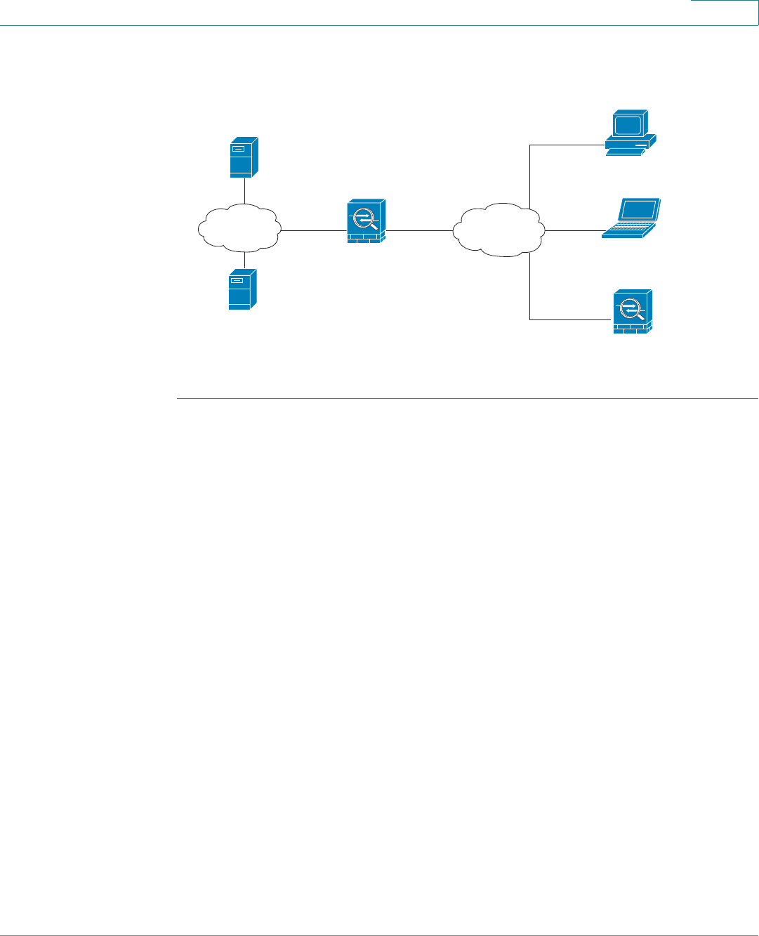
Wizards
Using the Remote Access Wizard to Establish the IPSec VPN Tunnels or SSL VPN Tunnels for Remote
Access
Cisco ISA500 Series Integrated Security Appliance Administrator Guide 59
2
Figure 1 IPSec Remote Access with a Cisco VPN Client Software or a Cisco
Device as a Cisco VPN Hardware Client
STEP 1 Click Wizards -> Remote Access.
The Getting Started window opens.
STEP 2 To establish the IPSec VPN tunnel for remote access, choose Cisco IPSec VPN as
the VPN tunnel type.
STEP 3 Click Begin.
The Group Setting window opens. From this page you can specify the Cisco
IPSec VPN server group policy:
•Group Name: Enter the name for the group policy.
•IKE Authentication Method: Specify the authentication method.
-Preshare Key: If you choose this option, enter the desired value that the
peer device must provide to establish a connection. The pre-shared key
must be entered exactly the same here and on the remote clients.
-Certificate: If you choose this option, choose a local certificate and a
remote certificate for authentication. On the remote clients, the selected
local certificate should be set as the remote certificate, and the selected
remote certificate should be set as the local certificate. If the certificate
is not in the list, go to the Device Management -> Certificate
Management page to import the certificates. See Managing the
Certificates for Authentication, page 310.
Inside
10.10.10.0
Outside
ISA500
as a Cisco IPSec VPN Server
DNS Server
10.10.10.163
WINS Server
10.10.10.133
Internet
Internal
network Personal Computer
running Cisco VPN Client software
Personal Computer
running Cisco VPN Client software
Cisco Device
as a Cisco VPN hardware client
Wizards
Using the Remote Access Wizard to Establish the IPSec VPN Tunnels or SSL VPN Tunnels for Remote
Access
Cisco ISA500 Series Integrated Security Appliance Administrator Guide 60
2
STEP 4 After you are finished, click Next.
The WAN Setting window opens. From this page you can choose the WAN
interface that the traffic passes through over the IPSec VPN tunnel. If you have two
links, you can enable WAN Failover to redirect the traffic to the secondary link
when the primary link is down.
•WAN Failover: Click On to enable WAN Failover, or click Off to disable it.
NOTE To enable the WAN Failover for Cisco IPSec VPN tunnels, make sure
that the secondary WAN interface was configured and the WAN
redundancy was set to the Loab Balancing or Failover mode.
NOTE The security appliance will automatically update the local WAN
gateway for the VPN tunnel based on the configurations of the backup
WAN link. For this purpose, Dynamic DNS has to be configured
because the IP address will change due to failover, or let the remote
gateway use a dynamic IP address.
•WAN Interface: Choose the WAN interface that the traffic passes through
over the IPSec VPN tunnel.
STEP 5 After you are finished, click Next.
The Network Setting window opens. From this page you can configure the mode
of operation. The operation mode determines whether the inside host relative to
the Cisco VPN hardware client is accessible from the corporate network over the
tunnel. Specifying a operation mode is mandatory before making a connection
because the Cisco VPN hardware client does not have a default mode. For more
information, see Modes of Operation, page 240.
•Client: Choose this mode for the group policy that is used for both the PC
running the Cisco VPN Client software and the Cisco device that supports
the Cisco VPN hardware client. In client mode, the server can assign the IP
address to the outside interface of remote clients. To define the pool range
for the clients, enter the starting and ending IP addresses in the Start IP and
End IP fields.
Wizards
Using the Remote Access Wizard to Establish the IPSec VPN Tunnels or SSL VPN Tunnels for Remote
Access
Cisco ISA500 Series Integrated Security Appliance Administrator Guide 61
2
•NEM: Choose this mode for the group policy that is only used for the Cisco
device that supports the Cisco VPN hardware client. The Cisco VPN
hardware client will obtain a private IP address from a DHCP server over the
IPSec VPN tunnel.
STEP 6 After you are finished, click Next.
The Access Control Setting window opens. From this page you can control the
access from the PC running the Cisco VPN Client software or the private network
of the Cisco VPN hardware client to the zones over the IPSec VPN tunnels. Click
Permit to permit the access, or click Deny. By default, the access for all zones is
permitted.
NOTE The VPN access rules that generated by the Zone Access Control settings
will be automatically added to the firewall access rule table with the priority
higher than the default access rules, but lower than the custom access rules.
STEP 7 After you are finished, click Next.
The DNS/WINS Setting window opens. From this page you can specify the DNS
and domain settings:
•Primary DNS Server: Enter the IP address of the primary DNS server.
•Secondary DNS Server: Enter the IP address of the secondary DNS server.
•Primary WINS Server: Enter the IP address of the primary WINS server.
•Secondary WINS Server: Enter the IP address of the secondary WINS
server.
•Default Domain: Enter the default domain name.
STEP 8 After you are finished, click Next.
The Backup Server Setting window opens. From this page you can specify up to
three backup servers. When the primary server is down, the client can connect to
the backup servers.
•Backup Server 1/2/3: Enter the IP addresses of backup servers. The
backup server 1 has the highest priority and the backup server 3 has the
lowest priority.

Wizards
Using the Remote Access Wizard to Establish the IPSec VPN Tunnels or SSL VPN Tunnels for Remote
Access
Cisco ISA500 Series Integrated Security Appliance Administrator Guide 62
2
NOTE The backup servers specified on the Cisco IPSec VPN server will be
sent to remote clients when initiating the VPN connection. The remote
clients will cache them.
•Peer Timeout: Enter the time in minutes that the client retries to connect the
backup server.
STEP 9 After you are finished, click Next.
The Split Tunnel Setting window opens. From this page you can specify the split
tunneling settings:
•Split Tunnel: Click On to enable the split tunneling feature, or click Off to
disable it. Split tunneling allows only the traffic that is specified by the VPN
client routes to corporate resources through the VPN tunnel. If you enable the
split tunneling feature, you need to define the split subnets. To add a subnet,
enter the IP address in the IP filed and and netmask address in the Netmask
filed, and then click Add. To delete a subnet, choose a subnet from the list
and then click Delete.
STEP 10 After you are finished, click Next.
The Cisco IPSec VPN-Group Policy Summary window opens. The Group Policy
Summary page displays the summary information for all configurations that you
made for the Cisco IPSec VPN group policy.
STEP 11 Click Next to configure the Cisco IPSec VPN user group settings.
The Cisco IPSec VPN - User Group Setting window opens. From this page you
can configure the user groups and enable the Cisco IPSec VPN service for them.
The users in the specified user group can use the Cisco IPSec VPN group policies
to establish the IPSec VPN tunnels. For complete details, see Configuring the
Cisco IPSec VPN User Groups, page 63.
STEP 12 After you are finished, click Next.
The Cisco IPSec VPN Summary window opens. The Summary page displays the
summary information for all Cisco IPSec VPN group policies and user groups you
made.
STEP 13 Click Submit to save your settings and exit the Remote Access Wizard.

Wizards
Using the Remote Access Wizard to Establish the IPSec VPN Tunnels or SSL VPN Tunnels for Remote
Access
Cisco ISA500 Series Integrated Security Appliance Administrator Guide 63
2
Configuring the Cisco IPSec VPN User Groups
In the Cisco IPSec VPN - User Group Setting window, follow these procedures to
create a Cisco IPSec VPN user group.
STEP 1 Click Add to add a Cisco IPSec VPN user group.
Other options: To edit an entry, click Edit. To delete an entry, click Delete. To
delete multiple entries, check the boxes of multiple entries and click Delete
Selection.
After you click Add, the New Group - Add/Edit window opens.
STEP 2 In the Group Settings tab, enter the following information:
•Name: Enter an unique name that contains the letters, numbers, or underline
for the Cisco IPSec VPN user group.
•Services: Specify the service policy for the group. The Cisco IPSec VPN
service must be enabled for this user group so that all members of the group
to securely access your network resources over the IPSec VPN tunnels.
STEP 3 In the Membership tab, specify the members of the user group.
•To add a member, select an existing user from the User list and then click the
right arrow ->. The members of the groups appear in the Membership list.
•To delete a member from the group, select the member from the
Membership list and then click the left arrow <-.
•To create a new user, enter the user name in the User Name field and the
password in the Password field, enter the password again in the Password
Confirm field, and click Create.
STEP 4 Click OK to save your settings.
Using SSL VPN to Establish the SSL VPN Tunnels
Use the Remote Access Wizard to set your security appliance as a SSL VPN
gateway to establish the SSL VPN tunnels and allow remote users to securely
access the corporate network resources.
STEP 1 Click Wizards -> Remote Access.
The Getting Started window opens.
Wizards
Using the Remote Access Wizard to Establish the IPSec VPN Tunnels or SSL VPN Tunnels for Remote
Access
Cisco ISA500 Series Integrated Security Appliance Administrator Guide 64
2
STEP 2 To establish the SSL VPN tunnels for remote access, choose SSL VPN as the VPN
tunnel type.
STEP 3 Click Begin.
The SSL VPN Configuration window opens.
STEP 4 In the Gateway (Basic) area, enter the following information:
•Gateway Interface: Choose the WAN interface that the traffic over the SSL
VPN tunnel passes through.
•Gateway Port: Enter the port number used on the SSL VPN gateway. HTTPS
or SSL typically operates on port 443. However, the SSL VPN gateway can
also operate on a user defined port. The firewall should permit the port to
ensure delivery of packets destined for the SSL VPN gateway. The SSL VPN
clients need to enter the entire address pair “Gateway IP Address: Port
Number” for connectting purposes.
•Certificate File: Choose a certificate to authenticate the users who want to
access your network resource through the SSL VPN tunnel.
•Client Address Pool: The SSL VPN gateway has a configurable address
pool with maximum size of 255 which is used to allocate IP addresses to the
remote clients. Enter the IP address pool for all remote clients. The client is
assigned an IP address by the SSL VPN gateway.
NOTE Configure an IP address range that does not directly overlap with any
of addresses on your local network.
•Client Netmask: Enter the IP address of the netmask used for SSL VPN
clients.
The Client Address Pool is used with the Client Netmask. If they are set as
follows, then the SSL VPN client will obtain a VPN address whose range is
from 10.0.0.1 to 10.0.0.254.
-Client Address Pool = 10.0.0.0
-Client Netmask = 255.255.255.0
•Client Domain: Enter the domain name used for the SSL VPN clients.
•Login Banner: After the user successfully logs into the SSL VPN server, a
configurable login banner is displayed. Enter the message text to display
along with the banner.
Wizards
Using the Remote Access Wizard to Establish the IPSec VPN Tunnels or SSL VPN Tunnels for Remote
Access
Cisco ISA500 Series Integrated Security Appliance Administrator Guide 65
2
STEP 5 In the Gateway (Advanced) area, enter the following information:
•Idle Timeout: Enter the timeout value in seconds that the SSL VPN session
can remain idle.
•Session Timeout: Enter the timeout value in seconds that the SSL VPN
session can remain connected.
•Client DPD Timeout: Dead Peer Detection (DPD) allows detection of dead
peers. Enter the DPD timeout for client in this field.
•Gateway DPD Timeout: Enter the DPD timeout for SSL VPN gateway in this
field.
•Keep Alive: If you want the SSL VPN server to keep sending a message at
an interval, enter the interval value in this field.
•Lease Duration: Enter the amount of time after which the SSL VPN client
must send an IP address lease renewal request to the server.
•Max MTU: Enter the maximum transmission unit for the session.
•Rekey Method: Specify the session rekey method (SSL or New Tunnel).
Rekey allows the SSL keys to be renegotiated after the session is
established.
•Rekey Interval: Enter the frequency of the rekey in this field.
STEP 6 After you are finished, click Next.
The SSL VPN Group Policy window opens. From this page you can configure the
SSL VPN goup policies. For complete details, see Configuring the SSL VPN
Group Policies, page 66.
NOTE The security appliance supports up to 32 SSL VPN goup policies.
STEP 7 After you are finished, click Next.
The SSL VPN-User Group Setting window opens. From this page you can
configure the SSL VPN user groups and enable the SSL VPN service for them. The
users in the specified user group can use the selected SSL VPN group policy to
establish the SSL VPN tunnels. For complete details, see Configuring the SSL
VPN User Groups, page 69.
STEP 8 After you are finished, click Next.

Wizards
Using the Remote Access Wizard to Establish the IPSec VPN Tunnels or SSL VPN Tunnels for Remote
Access
Cisco ISA500 Series Integrated Security Appliance Administrator Guide 66
2
The SSL VPN Summary window opens. The Summary page displays the
summary information for all SSL VPN group policies and user groups you made.
STEP 9 Click Submit to save your settings and exit the Remote Access Wizard.
Configuring the SSL VPN Group Policies
In the SSL VPN Group Policy window, follow these procedures to create a SSL
VPN goup policy.
STEP 1 To add a new SSL VPN group policy, click Add.
Other options: To edit an entry, click Edit. To delete an entry, click Delete. To
delete multiple entries, check the boxes of multiple entries and click Delete
Selection.
After you click Add, the Group Policy - Add/Edit window opens.
STEP 2 In the Basic Settings tab, enter the following information:
•Policy Name: Enter the name for the SSLP VPN group policy.
•Primary DNS: Enter the IP address of the primary DNS server.
•Secondary DNS: Enter the IP address of the secondary DNS server.
•Primary WINS: Enter the IP address of the primary WINS server.
•Secondary WINS: Enter the IP address of the secondary WINS server.
STEP 3 In the IE Proxy Settings tab, enter the following information:
The SSL VPN gateway can specify several Microsoft Internet Explorer (MSIE)
proxies for client PCs. If these settings are enabled, IE on the client PC is
automatically configured with these settings.
•IE Proxy Policy: Choose one of the following options:
-None: Allows the browser to use no proxy settings.
-Auto: Allows the browser to automatically detect proxy settings.
-Bypass-local: Allows the browser to bypass proxy settings that are
configured on the remote user.

Wizards
Using the Remote Access Wizard to Establish the IPSec VPN Tunnels or SSL VPN Tunnels for Remote
Access
Cisco ISA500 Series Integrated Security Appliance Administrator Guide 67
2
•Address: If you choose Bypass-Local, enter the IP address or domain name
of the MSIE proxy server. It is configured as an IPv4 address or fully qualified
domain name, followed by a colon and port number, for example
xxx.xxx.xxx.xxx:80.
•Port: Enter the port number of the MSIE proxy server.
•IE Proxy Exception: If you choose Bypass-Local, enter the IP address or
domain name of an exception host. This option allows the browser not to
send traffic for the given hostname or IP address through the proxy.
STEP 4 In the Split Tunneling Settings area, enter the following information:
Split tunnel mode permits specific traffic to be carried outside of the SSL VPN
tunnel. Traffic is either included (resolved in tunnel) or excluded (resolved through
the Internet Service Provider or WAN connection). Tunnel resolution configuration
is mutually exclusive. An IP address cannot be both included and excluded at the
same time.
•Enable Split Tunneling: By default, the SSL VPN gateway operates in full
tunnel mode which means that all of traffic from the host is directed through
the tunnel. Check the box to enable the Split Tunnel mode so that the tunnel
is used only for the traffic that is specified by the client routes.
•Split Include: If you enable split tunneling, choose one of the following
options:
-Include Traffic: Allows you to add the client routes on the SSL VPN client
so that only traffic to the destination networks redirected through the SSL
VPN tunnels.
To add a client route, enter the destination subnet to which a route is
added on the SSL VPN client in the Address field and the the subnet
mask for the destination network in the Netmask field, and then click
Add.
-Exclude Traffic: Allows you to exclude the destination networks on the
SSL VPN client. The traffic to the destination networks is redirected using
the SSL VPN clients native network interface (resolved through the
Internet Service Provider or WAN connection).
To add a destination subnet, enter the destination subnet to which a route
is excluded on the SSL VPN client in the Address field and the the subnet
mask for the excluded destination in the Netmask field, and then click
Add.
Wizards
Using the Remote Access Wizard to Establish the IPSec VPN Tunnels or SSL VPN Tunnels for Remote
Access
Cisco ISA500 Series Integrated Security Appliance Administrator Guide 68
2
-Exclude LAN: If you choose Exclude Traffic, click True to deny the SSL
VPN clients to access the local LANs over the VPN tunnel, or click False
to allow the SSL VPN clients to access the local LANs over the VPN
tunnel.
•Split DNS: Split DNS provides the ability to direct DNS packets in clear text
over the Internet to domains served through an external DNS (serving your
ISP) or through a SSL VPN tunnel to domains served by the corporate DNS.
For example, a query for a packet destined for corporate.com would go
through the tunnel to the DNS that serves the private network, while a query
for a packet destined for myfavoritesearch.com would be handled by the
ISP's DNS. By default, this feature is configured on the SSL VPN gateway and
is enabled on the client. To use Split DNS, you must also have Split Tunnel
mode configured.
To add a domain to the Cisco AnyConnect VPN Client for tunneling packets
to destinations in the private network, end the domian name in the field and
then click Add. To delete a domain, select it from the list and click Delete.
STEP 5 In the Zone-based Firewall Settings area, you can control the access over the
SSL VPN tunnels.
•Click Permit to permit the access from the SSL VPN clients to the zones.
•Click Deny to deny the access from the SSL VPN clients to the zones.
NOTE The VPN access rules that automatically generated by the zone-
based firewall settings will be added to the firewall access rule table
with the priority higher than the default firewall ACL rules, but lower
than the custom firewall ACL rules.
STEP 6 Click OK to save your settings.

Wizards
Using the Remote Access Wizard to Establish the IPSec VPN Tunnels or SSL VPN Tunnels for Remote
Access
Cisco ISA500 Series Integrated Security Appliance Administrator Guide 69
2
Configuring the SSL VPN User Groups
In the SSL VPN-User Group Setting window, follow these procedures to create a
SSL VPN user group.
STEP 1 Click Add to add a SSL VPN user group.
Other options: To edit an entry, click Edit. To delete an entry, click Delete. To
delete multiple entries, check the boxes of multiple entries and click Delete
Selection.
After you click Add, the New Group - Add/Edit window opens.
STEP 2 In the Group Settings tab, enter the following information:
•Name: Enter an unique name that contains the letters, numbers, or underline
for the SSL VPN user group.
•Services: Specify the service policy for the group. The SSL VPN service
must be enabled for this user group. Choose a SSL VPN group policy so that
all members of the group at the remote site can establish the SSL VPN
tunnels based on the selected SSL VPN group policy to access your
network resources.
STEP 3 In the Membership tab, specify the members of the user group.
•To add a member, select an exsiting user from the User list and then click the
right arrow ->. The members of the groups appear in the Membership list.
•To delete a member from the group, select the member from the
Membership list, and then click the left arrow <-.
•To create a new member, enter the user name in the User Name field and the
password in the Password field, enter the password again in the Password
Confirm field, and click Create.
STEP 4 Click OK to save your settings.

3
Cisco ISA500 Series Integrated Security Appliance Administrator Guide 70
Status
This chapter describes how to monitor the system status and performance for
your security appliance.
•System Status, page 70
•Interface Status, page 74
•Wireless Status for ISA550W and ISA570W, page 79
•Active Users, page 81
•VPN Status, page 81
•Reports, page 85
•Process Status, page 92
•Resource Utilization, page 92
To access the Status pages, click Status in the left hand navigation pane.
System Status
The Dashboard page displays the current system status. To open this page, click
Status -> Dashboard.
Router Information
System Name The device name of your security appliance.

Status
System Status
Cisco ISA500 Series Integrated Security Appliance Administrator Guide 71
3
Resource Utilization
To see complete details for resource utilization, click Details.
Licenses
Display the security license status. To manage the security license, click Manage.
Syslog Summary
Display the summary of the system event logs. Syslog entries are defined by
different severity levels. To see complete logs, click details.
Firmware
(Primary/
Secondary)
The firmware version that the security appliance is
currently using (primary) and the firmware version that was
previously running (secondary). By default, the security
appliance boots up with the primary firmware.
To switch to the secondary firmware, see Using the
Secondary Firmware, page 300.
Bootloader
Version
The bootloader version.
Serial Number The security appliance serial number.
PID The product identifier (PID) of the security appliance, also
known as product name, model name, and product number.
UDI The Unique Device Identifier (UDI) of the security appliance.
UID is Cisco’s product identification standard for hardware
products.
CPU Utilization The CPU usage.
Memory
Utilization
The allocated memory space after the security appliance
boots.
System Up Time How long the security appliance has been running.
Emergency Total number of Emergency logs. Click the number link for
details.
Alert Total number of Alert logs. Click the number link for details.

Status
System Status
Cisco ISA500 Series Integrated Security Appliance Administrator Guide 72
3
Site-to-Site VPN
Display the total number of Site-to-Site VPN sessions. To see complete details,
click details.
Remote Access VPN
Routing Mode
Display the routing mode between WAN and LAN. By default, the NAT mode is
enabled. Click details to enable or disable the Routing mode.
Physical Ports
To see complete details for all physical ports, click details.
Critical Total number of Critical logs. Click the number link for
details.
Error Total number of Error logs. Click the number link for details.
Warning Total number of Warning logs. Click the number link for
details.
Notification Total number of Notification logs. Click the number link for
details.
Information Total number of Information logs.
SSL Users Total number of active SSL VPN sessions. Click the SSL
Users link for details.
IPSec Users Total number of active IPSec VPN sessions that initiated by
your security appliance. Click the IPSec Users link for
details. This option is available when your security
appliance is set as the Cisco IPSec VPN Server or Cisco
IPSec VPN Client.
Single -
Dedicated Port
How many WAN interfaces are set, for example, Single -
Dedicated Port.
Name The name of the physical interface.
Port Type The port type of the physical interface.

Status
System Status
Cisco ISA500 Series Integrated Security Appliance Administrator Guide 73
3
WAN Mode
Display the WAN configuration mode of the security appliance (Single WAN port,
Failover, or Load Balancing). To see complete details for WAN redundancy, click
details.
WAN Interfaces
To see complete details for all WAN interfaces, click details.
LAN Interface
To see complete details for all VLANs, click details.
DMZ Interface
To see complete details for DMZ, click details.
Wireless Interface
To see complete details for all SSIDs, click details.
Mode The link status of the physical interface.
WAN1 to WAN
x
The name of the WAN interface.
IP Address The IP addresses assigned to the WAN interface.
Index The VLAN ID.
Name The VLAN name.
DHCP Mode The DHCP mode of the VLAN.
IP Address The subnet IP address of the VLAN.
Port The configurable interface that is set as the DMZ interface.
Name The name of the DMZ interface.
IP Address The subnet IP address of the DMZ interface.

Status
Interface Status
Cisco ISA500 Series Integrated Security Appliance Administrator Guide 74
3
Interface Status
The Interface Status pages display the ARP entries, IP address assignment of
DHCP pool, and the status and statistic information for all Ethernet ports, WANs,
VLANs, and DMZs. It includes the following sections:
•ARP Table, page 74
•DHCP Pool Assignment, page 75
•Interface, page 75
•Interface Statistics, page 77
ARP Table
The Address Resolution Protocol (ARP) is a computer networking protocol that
determines a network host’s Link Layer or hardware address when only the
Internet Layer (IP) or Network Layer address is known.
The ARP table displays the IP addresses and corresponding MAC addresses of
the devices under your local network. To open this page, click Status -> Interface
Status -> Show ARP Table.
SSID Number The SSID ID.
SSID Name The SSID name.
VLAN The VLANs to which the SSID is mapped.
Client List The number of client stations that are connected to the
SSID.
IP Address Indicates the station IP address, which is associated with
the MAC address.
MAC Address Indicates the station MAC address, which is associated
with the IP address.
Flag Indicates the ARP entry status.

Status
Interface Status
Cisco ISA500 Series Integrated Security Appliance Administrator Guide 75
3
DHCP Pool Assignment
The DHCP Pool Assignment page displays the IP address assignment by the
DHCP server on your security appliance. Click Refresh to refresh the data. To
open this page, click Status -> Interface Status -> DHCP Pool Assignment.
Interface
The Interface page displays the status for all Ethernet ports, WANs, VLANs, and
DMZs. To open this page, click Status -> Interface Status -> Interface.
Ethernet Table
The Ethernet table displays the following information for all physical ports:
Device Indicates the interface for which the ARP parameters are
defined.
IP Address The IP address assigned to the host or the remote device.
MAC Address The MAC address of the host or the remote device.
Lease Start
Time
The lease starting time of the IP address.
Lease End Time The lease ending time of the IP address.
Port The number of the physical port.
Name The name of the physical port.
Enable Shows if the physical port is enabled or disabled.
Port Type The physical port type, such as WAN, LAN, or DMZ.
Mode The physical port access mode. A WAN or DMZ port is
always set to Access mode and a LAN port can be set to
Access or Trunk mode.
VLAN The VLANs to which the physical port is mapped.

Status
Interface Status
Cisco ISA500 Series Integrated Security Appliance Administrator Guide 76
3
WAN Table
The WAN table displays the following information of all WAN interfaces:
VLAN Table
The VLAN table displays the following VLAN information:
PVID The Port VLAN ID (PVID) to be used to forward or filter the
untagged packets coming into the port. The PVID of a Trunk
port is fixed to the DEFAULT VLAN (1).
Speed/Duplex The duplex mode (speed and duplex setting) of the
physical port.
Link Status Shows if the physical port is connected or not.
Name The name of the WAN interface.
WAN Type The network addressing mode used to connect to the
Internet for the WAN interface.
Connection Time How long the WAN interface is connected, in seconds.
Connection
Status
Shows if the WAN interface obtains an IP address
successfully or not. If yes, the connection status shows as
“Connected”.
MAC Address The MAC address of the WAN interface.
IP Address The IP address of the WAN interface that is accessible from
the Internet.
Netmask The IP address of subnet mask for the WAN interface.
Gateway The IP address of default gateway for the WAN interface.
DNS Server The IP address of the DNS server for the WAN interface.
Physical Port The physical interface that is associated with the WAN
interface.
Link Status Shows if the cable is inserted to the WAN interface or not. If
the link status shows as “Not Link”, the cable may be loose
or malfunctioning.
Zone The zone to which the WAN interface is assigned.

Status
Interface Status
Cisco ISA500 Series Integrated Security Appliance Administrator Guide 77
3
DMZ Table
The DMZ table displays the following DMZ information:
Interface Statistics
The Interface Statistics page displays the traffic data for active physical ports,
WANs, VLANs, and DMZs. This page is automatically updated every 10 seconds.
To open this page, click Status -> Interface Status -> Interface Statistics.
Ethernet Table
The Ethernet table displays the traffic data for all active physical ports:
Name The VLAN name.
VID The VLAN ID.
Address The subnet IP address and netmask of the VLAN.
Physical Port The physical ports that are assigned to the VLAN.
Zone The zone to which the VLAN is mapped.
Name The DMZ name.
VID The VLAN ID.
Address The subnet IP address and netmask of the DMZ.
Physical Port The physical port that is assigned to the DMZ.
Zone The zone to which the DMZ is mapped.
Port The name of the physical port.
Link Status Shows if the port is connected or not.
Tx Pxts The number of IP packets going out of the port.
Rx Pxts The number of IP packets received by the port.

Status
Interface Status
Cisco ISA500 Series Integrated Security Appliance Administrator Guide 78
3
WAN Table
The WAN table displays the traffic statistic information for all WAN ports:
VLAN Table
The VLAN table displays the flow statistic information for all VLANs:
Collisions The number of signal collisions that have occurred on this
port. A collision occurs when the port tries to send data at
the same time as a port on the other router or computer that
is connected to this port.
Tx B/s The number of bytes going out of the port per second.
Rx B/s The number of bytes received by the port per second.
Up Time How long the port has been active. The uptime is reset to
zero when the security appliance or the port is restarted.
Name The name of the WAN port.
Tx Pkts The number of IP packets going out of the WAN port.
Rx Pkts The number of IP packets received by the WAN port.
Collisions The number of signal collisions that have occurred on this
WAN port.
Tx B/s The number of bytes going out of the WAN port per
second.
Rx B/s The number of bytes received by the WAN port per
second.
Up Time How long the WAN port has been active. The uptime is
reset to zero when the security appliance or the WAN port
is restarted.
Name The VLAN name.
Tx Pkts The number of IP packets going out of the VLAN.
Rx Pkts The number of IP packets received by the VLAN.

Status
Wireless Status for ISA550W and ISA570W
Cisco ISA500 Series Integrated Security Appliance Administrator Guide 79
3
DMZ Table
The DMZ table displays the flow statistic information for all DMZs:
Poll Interval
Enter a value in seconds for the poll interval. This causes the page to re-read the
statistic information from the security appliance and refreshes the page
automatically.
To modify the poll interval, click Stop and then click Start to restart the automatic
refresh by using the specified poll interval.
Wireless Status for ISA550W and ISA570W
Use the Wireless pages to view the wireless status and the number of client
stations that are connected to the SSIDs. It includes the following sections:
•Wireless Status, page 80
•Client Status, page 81
Collisions The number of signal collisions that have occurred on this
VLAN.
Tx B/s The number of bytes going out of the VLAN per second.
Rx B/s The number of bytes received by the VLAN per second.
Up Time How long the LAN port has been active.
Name The name of the DMZ.
Tx Pkts The number of IP packets going out of the DMZ.
Rx Pkts The number of IP packets received by the DMZ.
Collisions The number of signal collisions that occurred on the DMZ.
Tx B/s The number of bytes going out of the DMZ per second.
Rx B/s The number of bytes received by the DMZ per second.
Up Time How long the DMZ port has been active.

Status
Wireless Status for ISA550W and ISA570W
Cisco ISA500 Series Integrated Security Appliance Administrator Guide 80
3
Wireless Status
The Wireless Status page displays the cumulative total of relevant wireless
statistics for all active SSIDs. The counters is reset when the security appliance
reboots. To open this page, click Status -> Wireless -> Wireless Status.
Wireless Table
The security appliance may have multiple SSIDs enabled and configured
concurrently. This table displays the following information of all active SSIDs.
Wireless Statistics Table
This table displays the traffic data for a given SSID.
SSID Number The SSID ID.
SSID Name The SSID name.
MAC The MAC address of the SSID.
VLAN The VLAN to which the SSID is mapped.
Client List The number of client stations that are connected to the
SSID.
Name The SSID name.
Tx Pkts The number of transmitted packets on the SSID.
Rx Pkts The number of received packets on the SSID.
Collisions The number of packet collisions reported to the SSID.
Tx B/s The number of transmitted bytes of information on the
SSID.
Rx B/s The number of received bytes of information on the SSID.
Up Time How long the SSID has been active.

Status
Active Users
Cisco ISA500 Series Integrated Security Appliance Administrator Guide 81
3
Client Status
The Client Status page displays the MAC address and IP address of all client
stations that are already connected to each SSID. Click Refresh to refresh the
data. To open this page, click Status -> Wireless -> Client Status.
Active Users
The Active Users page displays all active users who are currently logged into the
security appliance. Click the Logout button to terminate an active user session. To
open this page, click Status -> Active Users.
You can check the following user session information.
VPN Status
The VPN Status pages display the status and statistic information of IPSec and
SSL VPN sessions. You can manually connect or disconnect the VPN tunnels. It
includes the following sections:
•IPSec VPN Status, page 82
•SSL VPN Status, page 83
User Name The name of the logged user.
Address
Information
The host IP address from which the user accessed the
security appliance.
Login Method How the user logs into the security appliance, such as web
login, SSL VPN, or Cisco IPSec VPN.
Session Time How long the user logged into the security appliance.

Status
VPN Status
Cisco ISA500 Series Integrated Security Appliance Administrator Guide 82
3
IPSec VPN Status
The VPN Table page displays the status and statistic information for IPsec VPN
sessions. To open this page, click Status -> VPN Status -> VPN Table.
Status for all IPSec VPN Sessions
The Active Sessions tab displays the following IPsec VPN session information:
Statistics for all active IPSec VPN Sessions
The IPSec VPN Statistic tab displays the statistic information for all active IPsec
VPN sessions:
Name The name of the IPSec VPN policy that is used for the VPN
session.
VPN Type The connection type of the IPSec VPN session, such as
Site-to-Site, Cisco IPSec VPN Server, or Cisco IPSec VPN
Client.
WAN Interface The WAN interface used for the IPSec VPN session.
Remote
Gateway
The IP address of the remote gateway for a Site-to-Site
VPN session or the IP address of the remote VPN client for
a Cisco IPSec VPN session.
Local Network The subnet IP address and netmask of your local network.
Remote Network The subnet IP address and netmask of the remote network.
Connect Click this button to manually establish a VPN connection.
Disconnect Click this button to manually terminate an active VPN
connection.
Name The name of the IPSec VPN policy used for the VPN
session.
VPN Type The connection type of the IPSec VPN session.
WAN Interface The WAN interface used for the IPSec VPN session.

Status
VPN Status
Cisco ISA500 Series Integrated Security Appliance Administrator Guide 83
3
SSL VPN Status
The SSL VPN Monitoring page displays the status and traffic statistic information
of all SSL VPN sessions. To open this page, click Status -> VPN Status ->
SSLVPN Monitoring.
Status of all Active SSL VPN Sessions
The Sessions tab displays the following information of all active SSL VPN
sessions:
Remote
Gateway
The IP address of the remote gateway for a Site-to-Site
VPN session or the IP address of the remote VPN client for
a Cisco IPSec VPN session.
Tx Bytes The volume of traffic in Kilobytes transmitted from the VPN
tunnel.
Rx Bytes The volume of traffic in Kilobytes received from the VPN
tunnel.
Tx Pkts The number of IP packets transmitted from the VPN tunnel.
Rx Pkts The number of IP packets received from the VPN tunnel.
Session ID The SSL VPN session ID.
User Name The name of the connected SSL VPN user.
Client IP (Actual) The actual IP address used by the SSL VPN client.
Client IP (VPN) The virtual IP address assigned by the SSL VPN gateway.
Time Connected The amount of time since the user first established the
connection.
Disconnect Click this button to terminate an active SSL VPN session
and hence the associated SSL VPN tunnel.
Disconnect All Click this button to terminate all active SSL VPN sessions
and hence the associated SSL VPN tunnels.

Status
VPN Status
Cisco ISA500 Series Integrated Security Appliance Administrator Guide 84
3
Statistics for all SSL VPN Sessions or for a single SSL VPN session
The Statistic tab displays the global statistic information for all active SSL VPN
sessions or for each SSL VPN session.
In the Global Status area, the global statistic information is displayed. To clear the
global statistic information, click Clear Global.
The following statistic information for each SSL VPN session is displayed in the
table. To clear the statistic information of a single SSL VPN session, click Clear.
Active Users The number of all connected SSL VPN users.
In CSTP frames The number of CSTP frames received from all clients.
In CSTP bytes The total number of bytes in the CSTP frames received
from all clients.
In CSTP data The number of CSTP data frames received from all clients.
In CSTP control The number of CSTP control frames received from all
clients.
Out CSTP
frames
The number of CSTP frames sent to all clients.
Out CSTP bytes The total number of bytes in the CSTP frames sent to all
clients.
Out CSTP data The number of CSTP data frames sent to all clients.
Out CSTP
control
The number of CSTP control frames sent to all clients.
Session ID The SSL VPN session ID.
In CSTP frames The number of CSTP frames received from the client.
In CSTP bytes The total number of bytes in the CSTP frames received
from the client.
In CSTP data The number of CSTP data frames received from the client.
In CSTP control The number of CSTP control frames received from the
client.
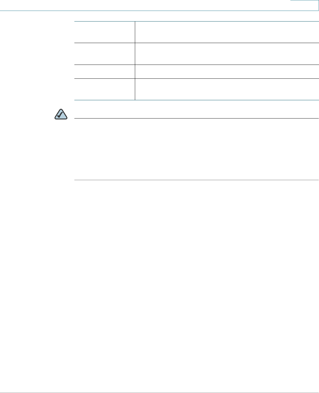
Status
Reports
Cisco ISA500 Series Integrated Security Appliance Administrator Guide 85
3
NOTE CSTP is a Cisco proprietary protocol for SSL VPN tunneling. “In” means “from the
client” and “Out” means “to the client”. The client is the PC running the Cisco
AnyConnect VPN Client software that connects to the security appliance running
the SSL VPN server. A CSTP frame is a packet that carrying CSTP protocol
information. There are two major frame types, control frames and data frames.
Control frames implement control functions within the protocol. Data frames carry
the client data, such as the tunneled payload.
Reports
The security appliance provides the report ability to help the operator or
administrator analyze the system performance and security. It includes the
following sections:
•Reports of Event Logs, page 86
•Reports of WAN Bandwidth, page 87
•Reports of Security Services, page 87
Out CSTP
frames
The number of CSTP frames sent to the client.
Out CSTP bytes The total number of bytes in the CSTP frames sent to the
client.
Out CSTP data The number of CSTP data frames sent to the client.
Out CSTP
control
The number of CSTP control frames sent to the client.
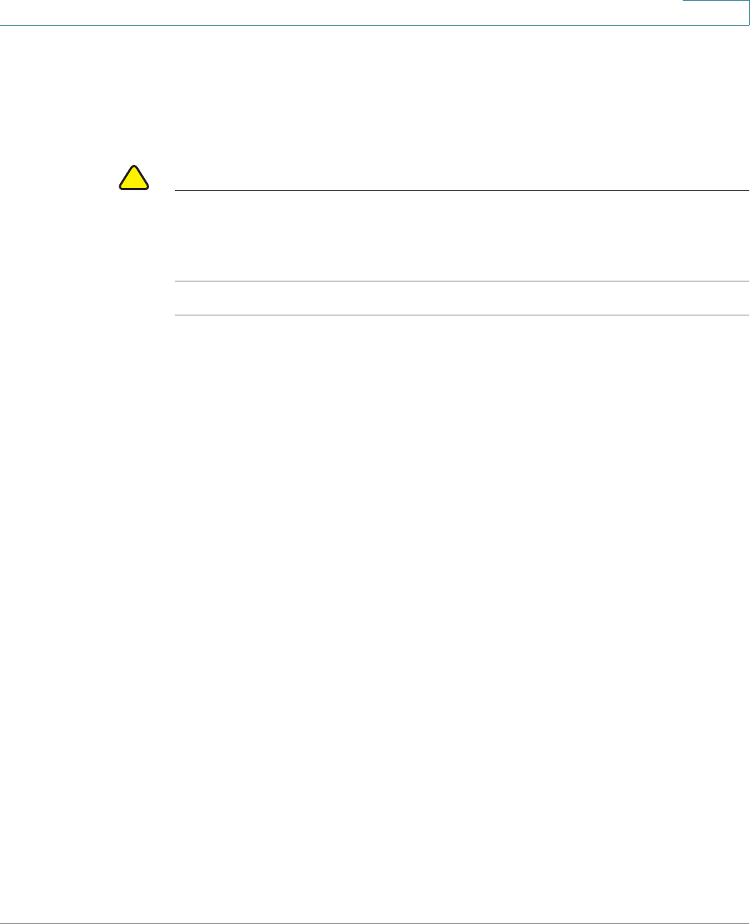
Status
Reports
Cisco ISA500 Series Integrated Security Appliance Administrator Guide 86
3
Reports of Event Logs
The security appliance can perform a rolling analysis of the event logs. The Report
page displays the top 25 most frequently accessed websites, the top 25 users of
bandwidth usage, and the top 25 services that consume the most bandwidth.
!
CAUTION Enabling the IP Bandwidth, Service Bandwidth, and TopN Web reports consumes
additional system resources and may impact the system performance. Go to the
Status -> Dashboard page to view the CPU and memory utilization. To conserve
the system resources, disable the reports when they are no longer needed.
STEP 1 To open the Report page, click Status -> Report -> Report.
STEP 2 Click On to enable a report, or click Off to disable a report.
STEP 3 Click Save to save your settings.
STEP 4 If you enable a report, choose this report from the Type drop-down list, the
corresponding statistic information is displayed.
•IP Bandwidth: This report lists the top 25 users of bandwidth usage. It
displays the number of megabytes transmitted per IP address since the
system is up.
•Service Bandwidth: This report lists the top 25 Internet services that
consume the most bandwidth. It displays the number of megabytes
received from the service since the system is up.
This report is helpful to determine whether the services being used are
appropriate for your organization. If the services such as video or push
broadcasts are consuming a large portion of the available bandwidth, you
can block them.
•Web Vistor: This report lists the top 25 most frequently accessed websites.
It displays the number of hits to a website since the system is up.
This report ensures that the majority of web access is to appropriate
websites. If inappropriate sites appear in this report, you can block the
websites. For more information on blocking inappropriate websites, see
Configuring the Content Filtering to Control Access to Internet,
page 201, or Web URL Filter, page 226.
Click on the domain name or site name of a website to open that site in a new
prompt window to see what this website is about.

Status
Reports
Cisco ISA500 Series Integrated Security Appliance Administrator Guide 87
3
STEP 5 Click Refresh Data to update the data on the screen or click Reset Data to reset
the values to zero.
Reports of WAN Bandwidth
The WAN Bandwidth report displays the run-time WAN network bandwidth usage
by hour in the past 24 hours.
STEP 1 Click Status -> Report -> WAN Bandwidth.
STEP 2 Check the Enable WAN Bandwidth box to enable this report.
STEP 3 Click Save to save your settings.
STEP 4 After you enable this report, in the Primary WAN tab, you can see the run-time
network bandwidth usage for the primary WAN interface by hour in the past 24
hours.
STEP 5 If a secondary WAN interface is configured, in the Secondary WAN tab, you can
see the run-time network bandwidth usage for the secondary WAN interface by
hour in the past 24 hours.
STEP 6 Click Reset to reset the network bandwidth usages for both the primary WAN and
secondary WAN interfaces.
Reports of Security Services
The Security Services page displays the statistical information for all enabled
security services. To open the pages, click Status -> Report -> Security
Services. It includes the following sections:
•Web Security Blocked Report, page 88
•Anti-Virus Report, page 88
•Email Security Report, page 89
•Network Reputation Report, page 90
•IPS Policy Protocol Inspection Report, page 90
•IM and P2P Blocking Report, page 91

Status
Reports
Cisco ISA500 Series Integrated Security Appliance Administrator Guide 88
3
NOTE The reports for the security services are provided only if the corresponding
security services are enabled.
Web Security Blocked Report
This report displays the number of web access requests logged and the number
of websites blocked by the Web URL Filter service, Web Reputation Filter service,
or both.
In the Web Security Blocked Report tab, check the Enable Web Security
Blocked Report box to enable this report, and then click Save to save your
settings.
After you enable this report, the corresponding statistic information is displayed.
Anti-Virus Report
This report displays the number of files checked and the number of viruses
detected by the Anti-Virus service.
In the Anti-Virus tab, check the Enable Anti-Virus Report box to enable this
report, and then click Save to save your settings.
After you enable this report, the corresponding statistic information is displayed.
Device System
Date
The current date for counting the data.
Total since the
service was
actived
The total number of web access requests processed and
the total number of websites blocked since the Web URL
Filter service, Web Reputation Filter service, or both were
enabled.
Total for las t 7
days
The total number of web access requests processed and
the total number of websites blocked in last seven days.
Total for today The total number of web access requests processed and
the total number of websites blocked in one day.
Graph Shows the total number of web access requests
processed and the total number of websites blocked by
day for last seven days.

Status
Reports
Cisco ISA500 Series Integrated Security Appliance Administrator Guide 89
3
Email Security Report
This report displays the number of emails checked and the number of spams or
supposed spams detected by the Email Reputation Filter service.
In the Email Security Report tab, check the Enable Email Security Report box to
enable this report, and then click Save to save your settings.
After you enable this report, the corresponding statistic information is displayed.
Device System
Date
The current date for counting the data.
Total since the
service was
actived
The total number of files checked and the total number of
viruses detected since the Anti-Virus service was enabled.
Total for las t 7
days
The total number of files checked and the total number of
viruses detected in last seven days.
Total for today The total number of files checked and the total number of
viruses detected in one day.
Graph Shows the total number of files checked and the total
number of viruses detected by day for last seven days.
Device System
Date
The current date for counting the data.
Total since the
service was
actived
The total number of emails checked and the total number of
spams or supposed spams detected since the Email
Reputation Filter service was enabled.
Total for las t 7
days
The total number of emails checked and the total number of
spams or supposed spams detected in last seven days.
Total for today The total number of emails checked and the total number of
spams or supposed spams detected in one day.
Graph Shows the total number of emails checked and the total
number of spams or supposed spams detected by day for
last seven days.

Status
Reports
Cisco ISA500 Series Integrated Security Appliance Administrator Guide 90
3
Network Reputation Report
This report displays the total number of packets checked and the number of
packets blocked by the Network Reputation service.
In the Network Reputation Report tab, check the Enable Network Reputation
Report box to enable this report, and then click Save to save your settings.
After you enable this report, the corresponding statistic information is displayed.
IPS Policy Protocol Inspection Report
This report displays the total number of packets for suspicious behaviors and
attacks (such as Denial-of-Service attacks, malware, and backdoor exploits)
detected and the number of packets dropped by the IPS service.
In the IPS Policy Protocol Inspection tab, check the Enable IPS Policy Protocol
Inspection Report box to enable this report, and then click Save to save your
settings.
After you enable this report, the corresponding statistic information is displayed.
Device System
Date
The current date for counting the data.
Total since the
service was
actived
The total number of packets checked and the total number
of packets blocked since the Network Reputation service
was enabled.
Total for las t 7
days
The total number of packets checked and the total number
of packets blocked in last seven days.
Total for today The total number of packets checked and the total number
of packets blocked in one day.
Graph Shows the total number of packets checked and the total
number of packets blocked by day for last seven days.
Device System
Date
The current date for counting the data.

Status
Reports
Cisco ISA500 Series Integrated Security Appliance Administrator Guide 91
3
IM and P2P Blocking Report
This report displays the number of packets for the predefined Instant Message
(IM) and Peer-to-Peer (P2P) applications detected, and the number of packets
blocked by the IPS service.
In the IM and P2P Blocking tab, check the Enable IM and P2P Blocking Report
box to enable this report, and then click Save to save your settings.
After you enable this report, the corresponding statistic information is displayed.
Total since the
service was
actived
The total number of packets for suspicious behaviors and
attacks detected and the total number of packets dropped
since both the IPS service and the IPS Policy and Protocol
Inspection were enabled.
Total for las t 7
days
The total number of packets for suspicious behaviors and
attacks detected and the total number of packets dropped
in last seven days.
Total for today The total number of packets for suspicious behaviors and
attacks detected and the total number of packets dropped
in one day.
Graph Shows the total number of packets for suspicious behaviors
and attacks detected and the total number of packets
dropped by day for last seven days.
Device System
Date
The current date for counting the data.
Total since the
service was
actived
The total number of packets for the predefined IM and P2P
applications detected and the total number of packets
blocked since both the IPS service and the IM & P2P
Blocking were enabled.
Total for las t 7
days
The total number of packets for the predefined IM and P2P
applications detected and the number of packets blocked
in the last seven days.
Total for today The total number of packets for the predefined IM and P2P
applications detected and the number of packets blocked
in one day.

Status
Process Status
Cisco ISA500 Series Integrated Security Appliance Administrator Guide 92
3
Process Status
The Process Status page displays the status for all sockets and the processes to
which each socket belongs. To open this page, click Status -> Process Status.
Resource Utilization
The Resource Utilization page displays the overall CPU and memory utilizations.
To open this page, click Status -> Resource Utilization.
Graph Shows the total number of packets for the predefined IM
and P2P applications detected and the total number of
packets blocked by day for last seven days.
Name The process name that is running on your security
appliance.
Description A brief description for the running process.
Protocol The protocol that is used by the socket.
Port The port number of the local end of the socket.
Local Address The IP address of the local end of the socket.
Foreign Address The IP address of the remote end of the socket.
CPU Utilization
CPU Usage by User The percentage of CPU resource used by user space
processes since the security appliance boots up.
CPU Usage by kernal The percentage of CPU resource used by kernel
space processes since the security appliance boots
up.
CPU Idle The percentage of CPU idle since the security
appliance boots up.

Status
Resource Utilization
Cisco ISA500 Series Integrated Security Appliance Administrator Guide 93
3
CPU Waiting for I/O The percentage of CPU waiting for I/O since the
security appliance boots up.
Memory Utilization
Total Memory The total amount of memory space available on the
security appliance.
Used Memory The amount of memory space used by the processes
at current time.
Free Memory The amount of memory space not used by the
processes at current time.
Cached Memory The amount of memory space used as cache at
current time.
Buffer Memory The amount of memory space used as buffers at
current time.

4
Cisco ISA500 Series Integrated Security Appliance Administrator Guide 94
Networking
This chapter describes how to configure your Internet connection, VLAN, DMZ,
zones, routing, Quality of Service, and related features. It includes the following
sections:
•Configuring IP Routing Mode, page 95
•Port Management, page 95
•Configuring the WAN, page 101
•Configuring the WAN Redundancy, page 112
•Configuring the VLAN, page 118
•Configuring the DMZ, page 123
•Configuring the Zones, page 127
•Configuring the Routing, page 130
•Dynamic DNS, page 136
•IGMP, page 138
•VRRP, page 139
•Configuring the Quality of Service, page 140
•Address Management, page 152
•Service Management, page 154
To access the Networking pages, click Networking in the left hand navigation
pane.

Networking
Configuring IP Routing Mode
Cisco ISA500 Series Integrated Security Appliance Administrator Guide 95
4
Configuring IP Routing Mode
Internet Protocol Version 6 (IPv6) is a new IP protocol designed to replace IPv4, the
Internet protocol that is predominantly deployed and extensively used throughout
the world. IPv6 quadruples the number of network address bits from 32 bits (in
IPv4) to 128 bits, resulting in an exponentially larger address space. You can
configure the security appliance to support IPv6 addressing on the WAN, LAN, and
DMZ.
By default, only IPv4 addressing is supported. If you need to configure IPv6
addressing, enable the IPv4/IPv6 mode.
STEP 1 Click Networking -> IPv4/IPv6 Routing Mode.
The IPv4/IPv6 Routing Mode window opens.
STEP 2 Click IPv4/IPv6 mode to enable both IPv4 and IPv6 addressing, or click IPv4 only
mode to enable only IPv4 addressing.
STEP 3 Click Save to save your settings.
Port Management
This section describes how to configure the physical ports, enable or disable the
port mirroring, and configure 802.1X access control settings on the physical ports.
It includes the following topics:
•Viewing the Status of Physical Interfaces, page 95
•Configuring the Physical Interfaces, page 96
•Configuring 802.1X Access Control on Physical Ports, page 98
•Configuring the Port Mirroring, page 100
Viewing the Status of Physical Interfaces
STEP 1 Click Networking -> Port -> Physical Interface.
The Physical Interface window opens.

Networking
Port Management
Cisco ISA500 Series Integrated Security Appliance Administrator Guide 96
4
In the Physical Interfaces area, all physical ports available on your security
appliance are listed in the table. The following information is displayed:
•Name: The name of the physical port.
•Enable: Shows if the physical port is enabled or disabled.
•Port Type: The physical port type, such as WAN, LAN, or DMZ. The type of
the dedicated WAN and LAN ports cannot be changed, but the type of the
configurable ports can be set to LAN, WAN, or DMZ.
•Mode: The physical port access mode. A WAN or DMZ port is always set to
Access mode. A LAN port can be set to Access or Trunk mode.
•VLAN: The VLANs to which the physical port is mapped.
•PVID: The Port VLAN ID (PVID) to be used to forward or filter the untagged
packets coming into port. The PVID of a trunk port is fixed to the DEFAULT
VLAN (1).
•Speed/Duplex: The duplex mode (speed and duplex setting) of the physical
port.
•Link Status: Shows if the physical port is connected or not.
If you are using the ISA550W or ISA570W, in the Wireless Interfaces area, all
active SSIDs available on your security appliance are listed in the table. The
following information is displayed:
•SSID Name: The SSID name.
•VLAN: The VLAN to which the SSID is mapped.
•Client List: The number of client stations that are connected to the SSID.
To configure the wireless radio and connectivity settings, go to the Wireless
pages. See Wireless Configuration for ISA550W and ISA570W.
Configuring the Physical Interfaces
You can enable or disable a physical interface, assign the physical interfaces to
VLANs, and configure the duplex mode.
STEP 1 Click Networking -> Port -> Physical Interface.
The Physical Interface window opens.
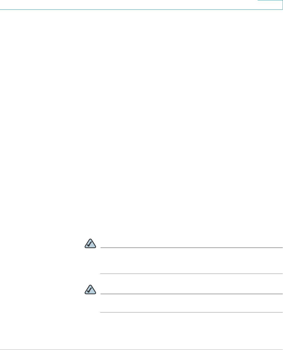
Networking
Port Management
Cisco ISA500 Series Integrated Security Appliance Administrator Guide 97
4
STEP 2 To edit the setting of a physical port, click Edit.
After you click Edit, the Ethernet Configuration - Add/Edit window opens.
STEP 3 Enter the following information:
•Name: The name of the physical port.
•Port Type: The physical port type, such as WAN , LAN, or DMZ.
•Mode: Choose either Access or Trunk mode for a LAN port, and choose
Access mode for a WAN or DMZ port. By default, all ports are set to Access
mode.
-Access: All data going into and out of the Access port is untagged.
Access mode is recommended if the port is connected to a single end-
user device which is VLAN unaware.
-Trunk: All data going into and out of the Trunk port is tagged. Untagged
data coming into the port is not forwarded, except for the DEFAULT VLAN,
which is untagged. Trunk mode is recommended if the port is connected
to a VLAN-aware switch or router.
•Port: Click On to enable the port, or click Off to disable it. By default, all ports
are enabled.
•VLAN: You can assign the physical port to VLANs.
-To assign the port to a VLAN, choose an existing VLAN from the Availbale
VLAN list and click the right arrows >> to add it to the VLAN list.
-To release the port from a VLAN, choose a VLAN from the VLAN list and
click the left arrows <<.
NOTE A LAN port can be assigned to multiple VLANs, but an Access LAN
port can only be assigned to one VLAN. A DMZ port must be assigned
to a DMZ network.
NOTE To create new VLANs, click Create VLAN. For more information about
how to configure the VLANs, see Configuring the VLAN, page 118.
•Flow Control: Click On to control the flow on the port, or click Off to disable
it.

Networking
Port Management
Cisco ISA500 Series Integrated Security Appliance Administrator Guide 98
4
•Speed: Choose one of these options: AUTO, 10 Mbps, 100 Mbps, and 1000
Mbps. The default is AUTO for all ports. The AUTO option lets the system and
network determine the optimal port speed.
•Duplex: Choose either Half Duplex or Full Duplex based on the port support.
The default is Full Duplex for all ports.
-Full: Indicates that the port supports transmissions between the device
and the client in both directions simultaneously.
-Half: Indicates that the port supports transmissions between the device
and the client in only one direction at a time.
STEP 4 Click OK to save your settings.
STEP 5 Repeat the above steps to edit the settings for other physical ports.
STEP 6 Click Save to apply your settings.
Configuring 802.1X Access Control on Physical Ports
Port-Based Access Control configures IEEE 802.1X port-based authentication to
prevent unauthorized devices (802.1X-capable clients) from gaining access to the
network.
The IEEE 802.1X standard defines a client-server-based access control and
authentication protocol that restricts unauthorized devices from connecting to a
LAN through publicly accessible ports. The authentication server authenticates
each client (supplicant in Windows 2000, XP, Vista, Windows 7, and Mac OS)
connected to a port before making available any service offered by the security
appliance or the LAN.
Until the client is authenticated, 802.1X access control allows only Extensible
Authentication Protocol over LAN (EAPOL) traffic through the port to which the
client is connected. After authentication is successful, normal traffic can pass
through the port.
This feature simplifies the security management by allowing you to control access
from a master database in a single server (although you can use up to three
RADIUS servers to provide backups in case access to the primary server fails). It
also means that user can enter the same authorized RADIUS username and
password pair for authentication, regardless of which switch is the access point
into the LAN.

Networking
Port Management
Cisco ISA500 Series Integrated Security Appliance Administrator Guide 99
4
STEP 1 Click Networking -> Port -> Port-Based Access Control.
The Port-Based Access Control window opens.
STEP 2 Specify the RADIUS servers for authentication.
The security appliance predefines three RADIUS groups. You can choose a
predefined RADIUS group from the RADIUS Index drop-down list to authenticate
the users on 802.1X-capable clients. The RADIUS server settings of the selected
group are displayed. You can also edit the RADIUS server settings here but the
settings that you specify will replace the default settings of the selected group.
For more information, see Configuring the RADIUS Servers, page 319.
STEP 3 To configure the access control settings for a physical port, click Edit in the Action
column.
The Port-Base Access Control window opens.
STEP 4 Enter the following information:
•Access Control: Check the box to enable 802.1X access control. This
feature is not available for Trunk ports.
•Authenticated VLAN: If you enable 802.1X access control, choose the
authenticated VLAN to which this port is assigned. The users who
authenticated successfully can access the authenticated VLAN through the
port. If the authentication fails, block the access on the port.
•Guest Authenticated: If you enable 802.1X access control, check the box to
enable Guest Authentication.
•Authenticated VLAN: If you enable Guest Authentication, choose the guest
VLAN to be associated with the port. If the authentication fails, the port is
assigned to the selected guest VLAN instead of shutting down. For 802.1X-
incapable clients, the port is also assigned to the selected guest VLAN when
Guest Authentication is enabled.
STEP 5 You can perform other actions as follows:
•Access Control: Check the box in this column to enable 802.1X access
control, or uncheck the box to disable it.
•Guest Authentication: After you enable 802.1X access control, check the
box in this column to enable Guest Authentication, or uncheck the box to
disable it.
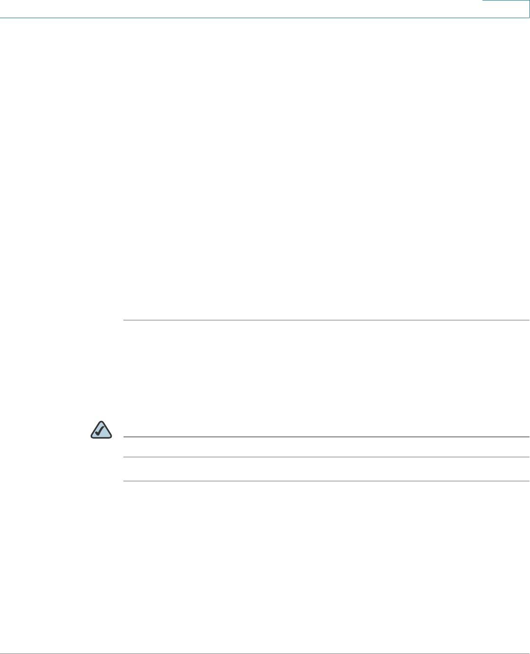
Networking
Port Management
Cisco ISA500 Series Integrated Security Appliance Administrator Guide 100
4
•Forced Authentication: Disables 802.1X access control and causes the port
to transition to the authorized state without any authentication exchange
required. The port transmits and receives normal traffic without 802.1X-
based authentication of the client.
•Forced Unauthentication: Causes the port to remain in the unauthorized
state, ignoring all attempts by the client to authenticate. The security
appliance cannot provide authentication services to the client through the
port.
•Auto: Enables 802.1X access control and causes the port to begin in the
unauthorized state, allowing only EAPOL frames to be sent and received
through the port. The authentication process begins when the link state of
the port transitions from down to up, or when an EAPOL-start frame is
received. The security appliance requests the identity of the client and
begins relaying authentication messages between the client and the
authentication server. Each client attempting to access the network is
uniquely identified by the security appliance by using the client's MAC
address.
STEP 6 Click Save to apply your settings.
Configuring the Port Mirroring
Port Mirroring allows the traffic on one port to be visible on other ports. This
feature is useful for debugging or traffic monitoring.
NOTE The dedicated WAN port (GE1 ) can not be set as a destination or monitored port.
STEP 1 Click Networking -> Port -> Port Mirroring.
The Port Mirroring window opens.
STEP 2 Click On to enable port mirroring, or click Off to disable it.
STEP 3 If you enable port mirroring, enter the following information:
•TX Destination: Choose the port that monitors the tranmitted traffic for other
ports.

Networking
Configuring the WAN
Cisco ISA500 Series Integrated Security Appliance Administrator Guide 101
4
•TX Monitored Ports: Check the boxes of the ports that are monitored. The
port that you set as a TX Destination port cannot be selected as a monitored
port.
•RX Destination: Choose the port that monitors the received traffic for other
ports.
•RX Monitored Ports: Check the boxes of the ports that are monitored. The
port that you set as a RX Destination port cannot be selected as a monitored
port.
STEP 4 Click Save to apply your settings.
Configuring the WAN
By default, the security appliance is configured to receive a public IP address from
your ISP automatically through DHCP. Depending on the requirements of your ISP,
you may need to modify the WAN settings to ensure Internet connectivity.
This section describes how to configure the WAN connections by using the
account information provided by your ISP. It includes the following sections:
•Configuring the Primary WAN, page 101
•Configuring the Secondary WAN, page 104
•Configuring the Network Addressing Mode, page 106
•Configuring the PPPoE Profiles, page 111
Configuring the Primary WAN
STEP 1 Click Networking -> WAN.
The WAN window opens.
STEP 2 To edit the settings of the primary WAN, click Edit.
After you click Edit, the WAN - Add/Edit window opens.
STEP 3 In the IPv4 tab, enter the following information:
•Physical Port: The physical port associated with the primary WAN.

Networking
Configuring the WAN
Cisco ISA500 Series Integrated Security Appliance Administrator Guide 102
4
•WAN Name: The name of the primary WAN (WAN1).
•IP Address Assignment: Choose the network addressing mode for the
primary WAN depending on the requirements of your ISP. The security
appliance supports DHCPC, Static IP, PPPoE, PPTP, and L2TP. For complete
details to configure the network addressing mode, see Configuring the
Network Addressing Mode, page 106.
•DNS Server Source: DNS servers map Internet domain names (example:
www.cisco.com) to IP addresses. You can get DNS server addresses
automatically from your ISP or use ISP-specified addresses.
-Get Dynamically from ISP: Choose this option if you have not been
assigned a static DNS IP address.
-Use These DNS Servers: Choose this option if your ISP assigned a static
DNS IP address. Also enter the addresses for the DNS1 and DNS2 fields.
•MAC Address Source: Specify the MAC address for the primary WAN.
Typically, you can use the unique 48-bit local Ethernet address of the
security appliance as your MAC address source.
-Use Default MAC Address: Choose this option to use the default MAC
address.
-Use the Following MAC Address: If your ISP requires MAC
authentication and another MAC address has been previously registered
with your ISP, choose this option and enter the MAC address that your ISP
requires for this connection.
•MAC Address: Enter the MAC Address in the format xx:xx:xx:xx:xx:xx where
x is a number from 0 to 9 (inclusive) or an alphabetical letter between A and
F (inclusive), for example, 01:23:45:67:89:ab.
•Zone: The primary WAN must be mapped to an untrusted zone. The WAN
zone is the default unstrusted zone. Click Create Zone to create other
untrusted zones. See Configuring the Zones, page 127.
STEP 4 In the IPv6 tab, specify the IPv6 addressing if you enable the IPv4/IPv6 mode.
•IP Address Assignment: Choose Static IP if your ISP assigned a fixed
(static or permanent) IP address. If you were not assigned a static IP address,
choose SLAAC. By default, your security appliance is configured to be a
DHCPv6 client of the ISP, with stateless address auto-configuration
(SLAAC).

Networking
Configuring the WAN
Cisco ISA500 Series Integrated Security Appliance Administrator Guide 103
4
-SLAAC: SLAAC provides a convenient method to assign IP addresses to
IPv6 nodes. This method does not require any human intervention from
an IPv6 user. If you choose SLAAC, the security appliance can generate
its own addresses using a combination of locally available information
and information advertised by routers.
-Static IP: If your ISP assigned a static IPv6 address, configure the IPv6
WAN connection in the following fields:
IPv6 Address: Enter the static IP address that was provided by your ISP.
IPv6 Prefix Length: The IPv6 network (subnet) is identified by the initial
bits of the address called the prefix. All hosts in the network have the
identical initial bits for their IPv6 address. Enter the number of common
initial bits in the network’s addresses. The default prefix length is 64.
Default IPv6 Gateway: Enter the IPv6 address of the gateway for your
ISP. This is usually provided by the ISP or your network administrator.
Primary DNS Server: Enter a valid IP address of the primary DNS Server.
Secondary DNS Server (Optional): Optionally, enter a valid IP address
of the secondary DNS Server.
STEP 5 Click OK to save your settings.
STEP 6 Click Save to apply your settings.
NOTE Next steps:
•To configure another ISP link, click Add. See Configuring the Secondary
WAN, page 104.
•To create multiple PPPoE profiles, go to the Networking -> PPPoE Profile
page. See Configuring the PPPoE Profiles, page 111.
•To determine how the two ISP links are used, you first need to add a
secondary WAN port, and then configure the WAN redundancy settings.
See Configuring the WAN Redundancy, page 112.
•If you are having problems with your WAN connection, see the Internet
Connection, page 333 in Troubleshooting, page 333.

Networking
Configuring the WAN
Cisco ISA500 Series Integrated Security Appliance Administrator Guide 104
4
Configuring the Secondary WAN
A secondary WAN is required to set up two ISP links for your network. You can use
one link as the primary link and another link for backup purposes, or you can
configure the load balancing to use both links simultaneously.
STEP 1 Click Networking -> WAN.
The WAN window opens.
STEP 2 To add the secondary WAN, click Add.
After you click Add, the WAN - Add/Edit window opens.
STEP 3 In the IPv4 tab, enter the following information:
•Physical Port: Choose a configurable port for the secondary WAN. The
selected configurable port is set to a WAN port. Up to two WAN interfaces
can be configured for the security appliance, which means that only one
configurable port can be set as a WAN port.
•WAN Name: The name of the secondary WAN (WAN2).
•IP Address Assignment: Choose the network addressing mode for the
secondary WAN depending on the requirements of your ISP. For complete
details, see Configuring the Network Addressing Mode, page 106.
•DNS Server Source: DNS servers map Internet domain names (example:
www.cisco.com) to IP addresses. You can get DNS server addresses
automatically from your ISP or use ISP-specified addresses.
-Get Dynamically from ISP: Choose this option if you have not been
assigned a static DNS IP address.
-Use These DNS Servers: Choose this option if your ISP assigned a static
DNS IP address. Also enter the addresses for the DNS1 and DNS2 fields.
•MAC Address Source: Specify the MAC address for the secondary WAN.
Typically, you can use the unique 48-bit local Ethernet address of the
security appliance as your MAC address source.
-Use Default MAC Address: Choose this option to use the default MAC
address
-Use the Following MAC Address: If your ISP requires MAC
authentication and another MAC address has been previously registered
with your ISP, choose this option and enter the MAC address that your ISP
requires for this connection.

Networking
Configuring the WAN
Cisco ISA500 Series Integrated Security Appliance Administrator Guide 105
4
•MAC Address: Enter the MAC address in the format xx:xx:xx:xx:xx:xx where
x is a number from 0 to 9 (inclusive) or an alphabetical letter between A and
F (inclusive), for example, 01:23:45:67:89:ab.
•Zone: Maps the secondary WAN to an untrusted zone. The WAN zone is the
default unstrusted zone. Click Create Zone to create other untrusted zones.
See Configuring the Zones, page 127.
STEP 4 In the IPv6 tab, specify the IPv6 addressing settings for the secondary WAN
connection if you enable the IPv4/IPv6 mode.
•IP Address Assignment: Choose Static IP if your ISP assigned a fixed
(static or permanent) IP address. If you were not assigned a static IP address,
choose SLAAC.
-SLAAC: If you choose SLAAC, the security appliance can generate its
own addresses using a combination of locally available information and
information advertised by routers.
-Static IP: If your ISP assigned a static IPv6 address, configure the IPv6
WAN connection in the following fields:
IPv6 Address: Enter the static IP address that was provided by your ISP.
IPv6 Prefix Length: The IPv6 network (subnet) is identified by the initial
bits of the address called the prefix. All hosts in the network have the
identical initial bits for their IPv6 address. Enter the number of common
initial bits in the network’s addresses. The default prefix length is 64.
Default IPv6 Gateway: Enter the IPv6 address of the gateway for your
ISP. This is usually provided by the ISP or your network administrator.
Primary DNS Server: Enter a valid IP address of the primary DNS Server.
Secondary DNS Server (Optional): Optionally, enter a valid IP address
of the secondary DNS Server.
STEP 5 Click OK to save your settings.
STEP 6 Click Save to apply your settings.

Networking
Configuring the WAN
Cisco ISA500 Series Integrated Security Appliance Administrator Guide 106
4
Configuring the Network Addressing Mode
The security appliance supports five types of network addressing modes.
Specify the network addressing mode for the primary WAN and the secondary
WAN depending on your ISP requirements.
Network
Addressing
Mode
Configurations
DHCPC DHCP is the default settting. If you use DHCP, the WAN port will
be the DHCP client and get the IP address from your ISP or the
peer router. Choose DHCP for most of Internet service providers
that use the cable modem.
Choose this option if your ISP automatically assigns you a
dynamic IP address, and enter the following information:
•MTU: The Maximum Transmission Unit is the size, in
bytes, of the largest packet that can be passed on.
Choose Auto to use the default MTU size, or choose
Manual if you want to specify another size.
•MTU Value: If you choose Manual, enter the custom MTU
size in bytes.
NOTE Unless a change is required by your ISP, it is recommended
that the MTU values be left as is.

Networking
Configuring the WAN
Cisco ISA500 Series Integrated Security Appliance Administrator Guide 107
4
Static IP Choose this option if your ISP assigns you a specific IP address
or a group of addresses. Use the corresponding information
from your ISP to complete the following fields:
•IP Address: Enter the IP address of the WAN port that
can be accessable from the Internet.
•Netmask: Enter the IP address of the subnet mask.
•Gateway: Enter the IP address of default gateway.
•DNS0: Enter the IP address of the primary DNS server.
•DNS1: Enter the IP address of the secondary DNS server.
•MTU: The Maximum Transmission Unit is the size, in
bytes, of the largest packet that can be passed on.
Choose Auto to use the default MTU size, or choose
Manual if you want to specify another size.
•MTU Value: If you choose Manual, enter the custom MTU
size in bytes.
NOTE Unless a change is required by your ISP, it is recommended
that the MTU values be left as is.
Network
Addressing
Mode
Configurations

Networking
Configuring the WAN
Cisco ISA500 Series Integrated Security Appliance Administrator Guide 108
4
PPPoE PPPoE uses Point to Point Protocol over Ethernet (PPPoE) to
connect to the Internet. The PPPoE protocol is typically found
when using a DSL modem. Choose this option if your ISP
provides you with client software, user name, and password.
Use the necessary PPPoE information from your ISP to
complete the PPPoE configurations. You can predefine multiple
PPPoE profiles before you set the network addressing mode as
PPPoE.
•Profile Name: Choose an existing PPPoE profile. The
User Name, Password, Authentication Type, and
Connectivity Type settings of the selected PPPoE profile
are displayed. You can edit the settings of the selected
PPPoE profile, or create a new PPPoE profile by choosing
Create a PPPoE Profile. See Configuring the PPPoE
Profiles, page 111.
•User Name/Password: Enter the user name and
password that are required to log into the ISP.
•Authentication Type: Choose the authentication type
specified by your ISP.
•Connect Idle Time: Choose this option to let the security
appliance disconnect from the Internet after a specified
period of inactivity (Idle Time). This choice is
recommended if your ISP fees are based on the time that
you spend online.
•Keep Live: Choose this option to keep the connection
always on, regardless of the level of activity. This choice
is recommended if you pay a flat fee for your Internet
service.
•MTU: Choose Auto to use the default MTU size, or
choose Manual if you want to specify another size.
•MTU Value: If you choose Manual, enter the custom MTU
size in bytes.
NOTE Unless a change is required by your ISP, it is recommended
that the MTU values be left as is.
Network
Addressing
Mode
Configurations

Networking
Configuring the WAN
Cisco ISA500 Series Integrated Security Appliance Administrator Guide 109
4
PPTP The PPTP protocol is typically used for VPN connection. Use
the necessary information from your ISP to complete the PPTP
configurations:
•IP Address: Enter the IP address of the WAN port that
can be accessable from the Internet.
•Netmask: Enter the IP address of the subnet mask.
•Gateway: Enter the IP address of default gateway.
•User Name/Password: Enter the user name and
password that are required to log into the PPTP server.
•PPTP Server IP Address: Enter the IP address of the
PPTP server.
•MPPE Encryption: Microsoft Point-to-Point Encryption
(MPPE) encrypts data in PPP-based dial-up connections
or PPTP VPN connections. Check the box to enable the
MPPE encryption to provide data security for the PPTP
connection that is between the VPN client and VPN
server.
•Connect Idle Time: Choose this option to let the security
appliance disconnect from the Internet after a specified
period of inactivity (Idle Time). This choice is
recommended if your ISP fees are based on the time that
you spend online.
•Keep Live: Choose this option to keep the connection
always on, regardless of the level of activity. This choice
is recommended if you pay a flat fee for your Internet
service.
•MTU: Choose Auto to use the default MTU size, or
choose Manual if you want to specify another size.
•MTU Value: If you choose Manual, enter the custom MTU
size in bytes.
NOTE Unless a change is required by your ISP, it is recommended
that the MTU values be left as is.
Network
Addressing
Mode
Configurations

Networking
Configuring the WAN
Cisco ISA500 Series Integrated Security Appliance Administrator Guide 110
4
L2TP Choose this option if you want to use IPSec to connect a L2TP
(Layer 2 Tunneling Protocol) server and encrypt all data
transmitted from the client to the server. However, it does not
encrypt network traffic to other destinations. Use the necessary
information from your ISP to complete the L2TP configurations:
•IP Address: Enter the IP address of the WAN port that
can be accessable from the Internet.
•Netmask: Enter the IP address of the subnet mask.
•Gateway: Enter the IP address of default gateway.
•User Name/Password: Enter the user name and
password that are required to log into the L2TP server.
•L2TP Server IP Address: Enter the IP address of the
L2TP server.
•Secret (Optional): L2TP incorporates a simple, optional,
CHAP-like tunnel authentication system during control
connection establishment. Enter the secret for tunnel
authentication if necessary.
•Connect Idle Time: Choose this option to let the security
appliance disconnect from the Internet after a specified
period of inactivity (Idle Time). This choice is
recommended if your ISP fees are based on the time that
you spend online.
•Keep Live: Choose this option to keep the connection
always on, regardless of the level of activity. This choice
is recommended if you pay a flat fee for your Internet
service.
•MTU: Choose Auto to use the default MTU size, or
choose Manual if you want to specify another size.
•MTU Value: If you choose Manual, enter the custom MTU
size in bytes.
NOTE Unless a change is required by your ISP, it is recommended
that the MTU values be left as is.
Network
Addressing
Mode
Configurations

Networking
Configuring the WAN
Cisco ISA500 Series Integrated Security Appliance Administrator Guide 111
4
NOTE Confirm that you have the proper network information from your ISP or a peer
router to configure the security appliance to access the Internet.
Configuring the PPPoE Profiles
If you have multiple PPPoE accounts, use the PPPoE Profile page to configure
multiple PPPoE profiles for later use.
STEP 1 Click Networking -> PPPoE Profile.
The PPPoE Profile window opens. All existing PPPoE profiles are listed in the table.
STEP 2 To add a new PPPoE profile, click Add.
Other options: To edit an entry, click Edit. To delete an entry, click Delete.
After you click Add or Edit, the PPPoE Profile - Add/Edit window opens.
STEP 3 Enter the following information:
•Name: Enter the name for the PPPoE profile.
•User Name: Enter the user name that is required to log into the ISP.
•Password: Enter the password that is required to log into the ISP.
•Authentication Type: Choose the method to authenticate the PPP sessions,
as specified by your ISP.
-Auto: The PPP protocol auto-negotiates the authentication method.
-PAP: Password authentication protocol (PAP) is used by PPP protocol to
validate the users before allowing them access to server resources.
Almost all network operating system remote servers support PAP.
-CHAP: Challenge Handshake Authentication Protocol (CHAP) is an
authentication scheme used by Point to Point Protocol (PPP) servers to
validate the identity of remote clients. CHAP periodically verifies the
identity of the client by using a three-way handshake. The verification is
based on a shared secret (such as the client user's password).
-MS-CHAP: MS-CHAP is the Microsoft version of the CHAP. The protocol
exists in two versions, MS-CHAPv1 (defined in RFC 2433) and MS-
CHAPv2 (defined in RFC 2759).
Networking
Configuring the WAN Redundancy
Cisco ISA500 Series Integrated Security Appliance Administrator Guide 112
4
-MS-CHAPv2: MS-CHAPv2 provides mutual authentication between
peers by piggybacking a peer challenge on the Response packet and an
authenticator response on the Success packet.
•Keep Live: Keeps the connection always on, regardless of the level of
activity. This option is recommended if you pay a flat fee for your Internet
service.
•Max Idle Time: Lets the security appliance disconnect from the Internet
after a specified period of inactivity (Idle Time). If you choose this option,
enter the value in minutes in the Maximum Idle Time field. This option is
recommended if your ISP fees are based on the time that you spend online.
•MTU: The Maximum Transmission Unit (MTU) is the size, in bytes, of the
largest packet that can be passed on. Choose Auto to use the default MTU
size, or choose Manual if you want to specify another size.
•MTU Size: If you choose Manual, enter the custom MTU size in bytes.
NOTE For PPPoE connections, the default MTU size is 1492 bytes. Unless a
change is required by your ISP, it is recommended that the MTU
values be left as is.
STEP 4 Click OK to save your settings.
STEP 5 Click Save to apply your settings.
Configuring the WAN Redundancy
If you have two ISP links, one for WAN1 and another for WAN2, you can configure
the WAN redundancy to determine how the two ISP links are used.
NOTE Before you configure the WAN redundancy, you must configure the secondary
WAN connection. See Configuring the Secondary WAN, page 104.

Networking
Configuring the WAN Redundancy
Cisco ISA500 Series Integrated Security Appliance Administrator Guide 113
4
NOTE When the security appliance is working in Dual WAN mode, if one WAN link is down,
the WAN redundancy and Policy-based Routing settings are ignored and all traffic
is handled by the active WAN port.
This section describes how to configure the WAN redundancy and the link failover
detection settings. It includes the following topics:
•Loading Balancing for WAN Redundancy, page 113
•Load Balancing with Policy-based Routing Configuration Example,
page 115
•Failover for WAN Redundancy, page 116
•Routing Table for WAN Redundancy, page 117
•Configuring the Link Failover Detection, page 117
Loading Balancing for WAN Redundancy
The Load Balancing can segregate traffic between links that are not of the same
speed. For example, you can bind the high-volume services through the port that
is connected to a high speed link, and bind the low-volume services to the port
that is connected to the slower link.
The Load Balancing is implemented for outgoing traffic and not for incoming traffic.
To maintain better control of WAN port traffic, consider making the WAN port
Internet address public and keeping the other one private.
Figure?2 shows an example of Dual WAN configured with the Load Balancing.
Figure 2 Example of Dual WAN Ports with Load Balancing
ISA500
yourcompany2.dyndns.org
yourcompany1.dyndns.org
Internet
Dual WAN Ports (Load Balancing)
WAN2 IP
WAN1 IP
197402
Networking
Configuring the WAN Redundancy
Cisco ISA500 Series Integrated Security Appliance Administrator Guide 114
4
NOTE To configure the Loading Balancing, make sure that you configure both WAN ports
to Keep Live. If the WAN port is configured to time out after a specified period of
inactivity, then the Loading Balancing is not applicable.
STEP 1 Click Networking -> WAN Redundancy -> WAN Redundancy Operation
Configuration.
The WAN Redundancy Operation Configuration opens.
STEP 2 Use the Load Balancing mode if you want to use both ISP links simultaneously. The
two links will carry data for the protocols that are bound to them. Enter the
following information:
•Equal Load Balancing (Round Robin): Re-orders the WAN interfaces for
Round Robin selection. The order is as follows: WAN1 and WAN2. The Round
Robin will then repeat back to WAN1 and continue the order. This is the
default setting.
•Weighted Load Balancing: Distributes the bandwidth to two WAN ports by
the weighted percange or by the weighted link bandwidth. If you choose this
mode, choose one of the following options and finish the setting:
-Weighted By Percentage: Allows you to set the percentage for each
WAN, such as 80% percentage bandwidth for WAN1 and lest 20%
percentage bandwidth for WAN2.
-Weighted By Link Bandwidth: Allows you to set the rate limiting for each
WAN, such as 10 Mbps for WAN1 and 5 Mbps for WAN2.
STEP 3 If you choose Load Balancing as the WAN redundancy operation mode, you can
optionally enable the Policy-based Routing (PBR) settings to determine how the
traffic is balanced between the two ISP links. The PBR settings specify the internal
IP and/or service going through a specified WAN port to provide more flexbile and
granular traffic handling capabilities.
•Policy Based Routing Enable: Click On to enable the PBR settings, or click
Off to disable it. To configure the PBR settings, click Configure PBR.
NOTE If you enable PBR, the PBR settings will be applied first and then the
load balancing settings next.

Networking
Configuring the WAN Redundancy
Cisco ISA500 Series Integrated Security Appliance Administrator Guide 115
4
STEP 4 Click Save to apply your settings.
STEP 5 To check the connection of both links at regular intervals after you enable the Load
Balancing mode, you first need to enable the Link Failover Detection feature. To
configure the Link Failover Detection settings, go to the Networking -> Link
Failover Detection Settings page. See Configuring the Link Failover Detection,
page 117.
Load Balancing with Policy-based Routing Configuration
Example
Use Cases: The customer has two lines, one is a cable link and another is a DSL
link. The majority of trafffic goes through the cable link since it has larger
bandwidth, and the rest traffic goes through the DSL link. As lots of secure
websites (such as bank, or online shopping) are sensitive to flip flop the source IP
address, let the traffic for https, ftp, video, and game go through the cable link.
Configuration Tasks:
•Configure a configurable port as the secondary WAN port (WAN2). See
Configuring the Secondary WAN, page 104.
•Connect the cable modem to the primary WAN port (WAN1), and connect
the DSL modem to the secondary WAN port (WAN2).
•Enable the Weighted Load Balancing mode, and set the weighted value of
WAN1 to 80% and the weighted value of WAN2 to 20%. See Loading
Balancing for WAN Redundancy, page 113.
•Enable the Policy-based Routing (PBR) feature, and configure PBR rules so
that the traffic for https, ftp, video, and game is directed to the WAN1 port.
See Configuring Policy-based Routing Settings, page 134.
•Enable the IP Bandwidth, Service Bandwidth, and WAN Bandwidth reports
so that you can check the WAN bandwidth usage by IP address, service,
and time. See Reports, page 85.
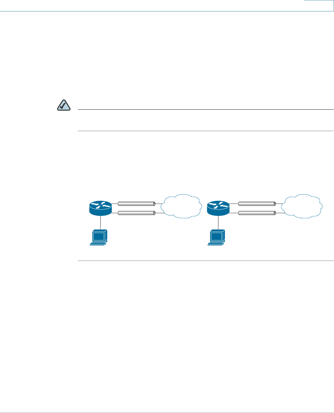
Networking
Configuring the WAN Redundancy
Cisco ISA500 Series Integrated Security Appliance Administrator Guide 116
4
Failover for WAN Redundancy
Use the Failover mode when you want to use one ISP link as a backup. If a failure is
detected on the primary link, then the security appliance directs all Internet traffic
to the backup link. When the primary link regains connectivity, all Internet traffic is
directed to the primary link and the backup link becomes idle. By default, the
primary WAN is set as the primary link and the secondary WAN is set to the
backup link.
NOTE When the security appliance is working in the Failover mode, the Policy-based
Routing settings will be ignored.
Figure?3 shows an example of Dual WAN configured with Failover.
Figure 3 Example Dual WAN Ports with Failover
STEP 1 Click Networking -> WAN Redundancy -> WAN Redundancy Operation
Configuration.
The WAN Redundancy Operation Configuration opens.
STEP 2 Choose Failover if you want to use one ISP link as a backup and enter the
following information:
•Auto Failover to: Choose either WAN1 or WAN2 as the primary link. By
default, WAN1 is set as the primary link and WAN2 is set as the backup link.
You can also set WAN2 as the primary link.
•Preempt Delay Timer: Enter the time in seconds that the system will
preempt the primary link from the backup link when the primary link is up
again. The default is 5 seconds.
STEP 3 Click Save to apply your settings.
ISA500
yourcompany.dyndns.org
XX
WAN2 port inactive
WAN2 IP (N/A)
Internet
Dual WAN Ports (Before Rollover)
ISA500
yourcompany.dyndns.org
XX
WAN1 IP (N/A)
WAN1 port inactive
Internet
Dual WAN Ports (After Rollover)
WAN1 IP
WAN2 IP
197401
Networking
Configuring the WAN Redundancy
Cisco ISA500 Series Integrated Security Appliance Administrator Guide 117
4
STEP 4 To check the connection of both links at regular intervals after you enable the
Failover mode, you first need to enable the Link Failover Detection feature. To
configure the Link Failover Detection settings, go to the Networking -> Link
Failover Detection Settings page. See Configuring the Link Failover Detection,
page 117.
Routing Table for WAN Redundancy
The Routing Table feature allows the traffic to meet the static routing policies you
defined on your security appliance to pass through different WAN interfaces.
You need to add default routing policies that forward the traffic to the primary
WAN. The traffic for other static routings are forwarded to the secondary WAN. For
more inforamtion to configure the static routing policies, see Configuring the
Static Routing, page 132.
NOTE The Link Failover Detection settings will be ignored if you enable the Routing Table
feature.
Configuring the Link Failover Detection
The Link Failover Detection feature detects the link failure. If a failure occurs, traffic
for the unavailable link is diverted to the active link.
NOTE The Link Failover Detection settings are only available when the WAN redundancy
is set to Load Balancing or Failover.
STEP 1 Click Networking -> WAN Redundancy -> Link Failover Detection Settings.
The Link Failover Detection Settings window opens.
STEP 2 Enter the following information:
•Failover Detection: Click On to enable the Link Failover Detection feature, or
click Off to disable it.

Networking
Configuring the VLAN
Cisco ISA500 Series Integrated Security Appliance Administrator Guide 118
4
•Retry Count: Enter the number of retries. The security appliance repeatedly
tries to connect to the ISP after the link failure is detected. The default is 5.
•Retry Timeout: If the connection to the ISP is down, the security appliance
tries to connect to the ISP after a specified timeout. Enter the timeout in
seconds to re-connect to the ISP. The default is 5 seconds.
•Ping Detection: Choose this option to detect the WAN failure by pinging the
IP address that you specify in the following fields:
-Ping using WAN Default Gateway: Ping the IP address of the WAN
default gateway. If the default WAN gateway can be detected, the
network connection is active.
-Ping using these Hosts: Ping the specified remote hosts. Enter the IP
addresses in the Primary WAN Remote Host and Secondary WAN
Remote Host fields. In Failover mode, if the primary WAN remote host
can be detected, the network connection is active. In Load Balancing
mode, if the primary WAN and secondary WAN remote hosts can be
detected, the WAN connection is active.
•DNS Detection: Choose this option to detect the WAN failure by looking up
the DNS servers that you specify in the following fields:
-DNS Lookup using WAN DNS Servers: The security appliance sends
the DNS query for www.cisco.com to the default WAN DNS server. If the
DNS server can be detected, the network connection is active.
-DNS Lookup using these DNS Servers: The security appliance sends
the DNS query for www.cisco.com to the specified DNS servers. Enter
the IP addresses in the Primary WAN DNS Server and Secondary WAN
DNS Server fields. If the primary or secondary DNS server can be
detected, the network connection is active.
STEP 3 Click Save to apply your settings.
Configuring the VLAN
The Virtual LANs (VLANs) allow you to segregate the network into LANs that are
isolated from one another. Any PC that is connected to the specified LAN port is
on a separate VLAN and cannot access other VLANs. You can add up to 16
VLANs.

Networking
Configuring the VLAN
Cisco ISA500 Series Integrated Security Appliance Administrator Guide 119
4
This section describes how to configure the VLANs. It includes the following
topics:
•Configuring the VLANs, page 119
•Configuring DHCP Reserved IPs, page 122
Configuring the VLANs
The security appliance predefines a native VLAN (DEFAULT) and a guest VLAN
(GUEST). You can change the settings for the predefined VLANs, or add new
VLANs, for up to a total of 16 VLANs. Any PC that is connected to the specified
LAN port is on a separate VLAN and cannot access other VLANs.
STEP 1 Click Networking -> VLAN.
The VLAN window opens.
STEP 2 To add a new VLAN, click Add.
Other options: To edit an entry, click Edit. To delete an entry, click Delete. The
default VLANs can not be deleted.
After you click Add or Edit, the VLAN - Add/Edit window opens.
STEP 3 In the Basic Setting tab, enter the following information:
•Name: Enter a descriptive name for the VLAN.
•VID: Enter an unique identification number for the VLAN, which can be any
number from 3 to 4089. The VLAN ID 1 is reserved for the DEFAULT VLAN
and the VLAN ID 2 is reserved for the GUEST VLAN.
•IP: Enter the subnet IP address for the VLAN.
•Netmask: Enter the subnet mask for the VLAN.
•Spanning Tree: Check the box to enable the Spanning Tree feature to
determine if there are loops in the network topology. The Spanning Tree
Protocol (STP) is a link layer network protocol that ensures a loop-free
topology for any bridged LAN. The STP is used to prevent bridge loops and
to ensure broadcast radiation.
•Port: Assigns the LAN ports to the VLAN. The traffic through the selected
LAN ports is directed to the VLAN. All available ports including the dedicated
LAN ports and configurable ports appear in the Port list.
Networking
Configuring the VLAN
Cisco ISA500 Series Integrated Security Appliance Administrator Guide 120
4
Choose the ports from the Port list and click ->Access to add them to the
Member list and set the selected ports as Access mode. All packets going
into and out of the Access ports are untagged. Access mode is
recommended if the port is connected to a single end-user device which is
VLAN unaware.
Alternatively, you can choose the ports from the Port list and click ->Trunk
to add them to the Member list and set the selected ports as Trunk mode. All
packets going into and out of the Trunk port are tagged. Untagged data
coming into the port is not forwarded. Trunk mode is recommended if the
port is connected to a VLAN-aware switch or router.
NOTE This setting will change the port type and access mode of the
selected physical ports. For example, choose a port that was set as a
DMZ port and add it to the Member list. The DMZ port will be changed
to a LAN port. Changing the port type will wipe out all configurations
relative to the physical port.
•Zone: Choose the zone to which the VLAN is mapped. By default, the
DEFAULT VLAN is mapped to the LAN zone and the GUEST VLAN is mapped
to the GUEST zone.
STEP 4 In the DHCP Pool Settings tab, choose the DHCP mode from the DHCP Server
drop-down list.
•Disable: Choose this option if the computers on the VLAN are configured
with static IP addresses or are configured to use another DHCP server.
•DHCP Server: Allows the security appliance to act as a DHCP server and
assigns IP addresses to all devices that are connected to the VLAN. Any new
DHCP client joining the VLAN is assigned an IP address of the DHCP pool.
•DHCP Relay: Allows the security appliance to use a DHCP Relay. If you
choose DHCP Relay, enter the IP address of the remote DHCP server in the
Relay IP field.
STEP 5 If you choose DHCP Server as the DHCP mode, enter the following information:
•Start IP: Enter the first IP address in the DHCP range.
•End IP: Enter the last IP address in the DHCP range. Any new DHCP client
joining the VLAN is assigned an IP address between the Start IP address and
End IP address.
Networking
Configuring the VLAN
Cisco ISA500 Series Integrated Security Appliance Administrator Guide 121
4
NOTE The Start and End IP addresses must be in the same subnet with the
VLAN IP address.
•Lease Time: Enter the maximum connection time that a dynamic IP address
is “leased” to a network user. When the time elapses, the user will be
automatically renewed the dynamic IP address.
•DNS 1: Enter the IP address of the primary DNS server.
•DNS 2: Optionally, enter the IP address of the secondary DNS server.
•WINS 1: Enter the IP address for the primary WINS server.
•WINS 2: Optionally, enter the IP address of the secondary WINS server.
•Domain Name: Optionally, enter the domain name for the VLAN
•Optional 66: Only supports the IP address or host name of a single TFTP
server. Enter the IP address of the single TFTP server for the VLAN.
•Optional 67: Enter the boot file name or configuration file name on the
specified TFTP server.
•Optional 150: Supports a list of TFTP servers (2 TFTP servers). Enter the IP
addresses of TFTP servers. Separate multiple entries with commas (,).
NOTE Enterprises with small branch offices that implement a Cisco IP
Telephony Voice over IP solution typically implement Cisco
CallManager at a central office to control Cisco IP Phones at small
branch offices. This implementation allows centralized call
processing, reduces the equipment required, and eliminates the
administration of additional Cisco CallManager and other servers at
branch offices. Cisco IP Phones download their configuration from a
TFTP server. When a Cisco IP Phone starts, if it does not have both the
IP address and TFTP server IP address pre-configured, it sends a
request with option 150 or 66 to the DHCP server to obtain this
information.
STEP 6 In the IPv6 Setting tab, specify the IPv6 addressing for the VLAN if you enable the
IIPv4/Pv6 mode.
•IPv6 Address: Enter the IPv6 address based on your network requirements.

Networking
Configuring the VLAN
Cisco ISA500 Series Integrated Security Appliance Administrator Guide 122
4
•IPv6 Prefix Length: Enter the number of characters in the IPv6 prefix.
The IPv6 network (subnet) is identified by the prefix, which consists of the
initial bits of the address. The default prefix length is 64 bits. All hosts in the
network have the identical initial bits for the IPv6 address. The number of
common initial bits in the addresses is set by the prefix length field.
STEP 7 Click OK to save your settings.
STEP 8 Click Save to apply your settings.
Configuring DHCP Reserved IPs
Even when the security appliance is configured to act as a DHCP server, you can
reserve certain IP addresses to always be assigned to specified devices.
Use the Static IP Reservations page to bind the MAC address of the device with
the desired IP address. Whenever the DHCP server receives a request from a
device, the hardware address is compared with the database. If the device is
found, then the reserved IP address is used. Otherwise, an IP address is assigned
automatically from the DHCP pool.
STEP 1 Click Networking -> Static IP Reservations.
The Static IP Reservations window opens.
STEP 2 To add a new reserved IP, click Add.
Other Options: To edit an entry, click Edit. To delete an entry, click Delete.
After you click Add or Edit, the Static IP Reservations - Add/Edit window opens.
STEP 3 Enter the following information:
•Name: Enter the name for the static IP reservation rule.
•MAC Address: Enter the MAC address of the host under a VLAN.
•IP Address: Enter the IP address within the VLAN’s DHCP pool that is
assigned to the host.
STEP 4 Click OK to save your settings.
STEP 5 Click Save to apply your settings.
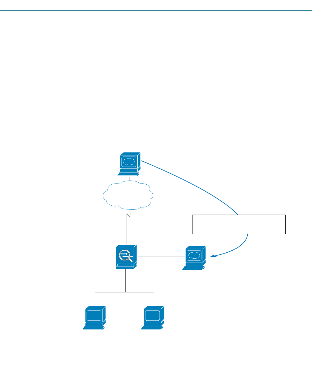
Networking
Configuring the DMZ
Cisco ISA500 Series Integrated Security Appliance Administrator Guide 123
4
Configuring the DMZ
A DMZ (Demarcation Zone or Demilitarized Zone) is a subnetwork that is behind
the firewall but that is open to the public. By placing your public services on a
DMZ, you can add an additional layer of security to the LAN. The public can
connect to the services on the DMZ but cannot penetrate the LAN. You should
configure your DMZ to include any hosts that must be exposed to the WAN (such
as web or email servers).
The DMZ configuration is identical to the VLAN configuration. There are no
restrictions on the IP address or subnet assigned to the DMZ port, except it cannot
be identical to the IP address given to the predefined VLANs.
Figure 4 Example DMZ with One Public IP Address for WAN and DMZ
235140
www.example.com
Internet
Public IP Address
209.165.200.225
ISA500
User
192.168.75.10
LAN Interface
192.168.75.1
DMZ Interface
172.16.2.1
Web Server
Private IP Address: 172.16.2.30
Public IP Address: 209.165.200.225
User
192.168.75.11
Source Address Translation
209.165.200.225 172.16.2.30
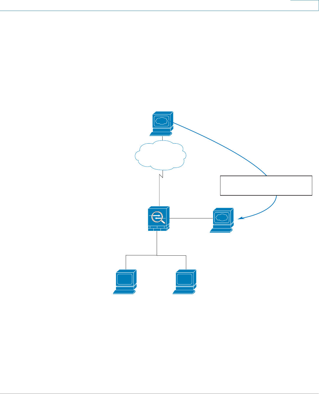
Networking
Configuring the DMZ
Cisco ISA500 Series Integrated Security Appliance Administrator Guide 124
4
In this scenario, the business has one public IP address, 209.165.200.225, which is
used for both the security appliance’s public IP address and the web server’s
public IP address. The administrator configures the configurable port to be used
as a DMZ port. A firewall access rule allows inbound HTTP traffic to the web
server at 172.16.2.30. Internet users enter the domain name that is associated with
the IP address 209.165.200.225 and can then connect to the web server. The
same IP address is used for the WAN interface.
Figure 5 Example DMZ with Two Public IP Addresses
In this scenario, the ISP has supplied two static IP addresses: 209.165.200.225
and 209.165.200.226. The address 209.165.200.225 is used for the security
appliance’s public IP address. The administrator configures the configurable port
to be used as a DMZ port and created a firewall access rule to allow inbound
User
192.168.75.10
235610
www.example.com
Internet
Public IP Addresses
209.165.200.225 (router)
209.165.200.226 (web server)
LAN Interface
192.168.75.1
ISA500
DMZ interface
172.16.2.1
Web Server
Private IP Address: 172.16.2.30
Public IP Address: 209.165.200.226
Source Address Translation
209.165.200.226 172.16.2.30
User
192.168.75.11
Networking
Configuring the DMZ
Cisco ISA500 Series Integrated Security Appliance Administrator Guide 125
4
HTTP traffic to the web server at 172.16.2.30. The firewall rule specifies an
external IP address of 209.165.200.226. Internet users enter the domain name that
is associated with the IP address 209.165.200.226 and can then connect to the
web server.
STEP 1 Click Networking -> DMZ.
The DMZ window opens.
STEP 2 To add a DMZ, click Add.
Other options: To edit an entry, click Edit. To delete an entry, click Delete.
After you click Add or Edit, the DMZ - Add/Edit window opens.
STEP 3 In the Basic Setting tab, enter the following information:
•Name: Enter the name for the DMZ.
•IP Address: Enter the subnet IP address for the DMZ.
•Netmask: Enter the subnet mask for the DMZ.
•Spanning Tree: Check the box to enable the Spanning Tree feature to
determine if there are loops in the network topology.
•Port: Specify a configurable port as a DMZ port. The traffic through the DMZ
port is directed to the DMZ. All available configurable ports appears in the
Port list, choose a port and click ->Access to add it to the Member list. The
selected configurable port will be set to a DMZ port with Access mode. All
data going into and out of the Access port is untagged.
NOTE This setting will change the port type and access mode of the
selected configurable port. Changing the port type will wipe out all
configurations relative to the physical port.
NOTE Up to five DMZ interfaces can be configured for ISA570 and
ISA570W. Up to four DMZ interfaces can be configured for ISA550
and ISA550W.
•Zone: Choose the default or custom DMZ zone to which the DMZ is mapped.
Networking
Configuring the DMZ
Cisco ISA500 Series Integrated Security Appliance Administrator Guide 126
4
STEP 4 In the DHCP Pool Settings tab, choose the DHCP mode from the DHCP Server
drop-down list.
•Disable: Choose this option if the computers on the DMZ are configured with
static IP addresses or are configured to use another DHCP server.
•DHCP Server: Allows the security appliance to act as a DHCP server and
assigns IP addresses to all devices that are connected to the DMZ. Any new
DHCP client joining the DMZ is assigned an IP address of the DHCP pool.
•DHCP Relay: Allows the security appliance to use a DHCP Relay. If you
choose DHCP Relay, enter the IP address of the remote DHCP server in the
Relay IP field.
STEP 5 If you choose DHCP Server as the DHCP mode, enter the following information:
•Start IP: Enter the first IP address in the DHCP range.
•End IP: Enter the last IP address in the DHCP range. Any new DHCP client
joining the DMZ is assigned an IP address between the Start IP address and
the End IP address.
NOTE The Start and End IP addresses must be in the same subnet with the
DMZ’s subnet IP address .
•Lease Time: Enter the maximum connection time that a dynamic IP address
is “leased” to a network user. When the time elapses, the user will be
automatically renewed the dynamic IP address.
•DNS 1: Enter the IP address of the primary DNS server.
•DNS 2: Enter the IP address of the secondary DNS server.
•WINS 1: Enter the IP address for the primary WINS server.
•WINS 2: Enter the IP address of the secondary WINS server.
•Domain Name: Enter the domain name for the DMZ.
•Default Gateway: Enter the IP address of default gateway.
STEP 6 In the IPv6 Setting tab, specify the IPv6 addressing for the DMZ if you enable the
IPv4/IPv6 mode.
•IPv6 Address: Enter the IPv6 address based on your network requirements.
•IPv6 Prefix Length: Enter the number of characters in the IPv6 prefix.
Networking
Configuring the Zones
Cisco ISA500 Series Integrated Security Appliance Administrator Guide 127
4
The IPv6 network (subnet) is identified by the prefix, which consists of the
initial bits of the address. The default prefix length is 64 bits. All hosts in the
network have the identical initial bits for the IPv16 address. The number of
common initial bits in the addresses is set by the prefix length field.
STEP 7 Click OK to save your settings.
STEP 8 Click Save to apply your settings.
NOTE Next steps:
•After you configure the DMZ, connect the local server that you want to
public to Internet to the specified DMZ port, and then configure a port
forwarding rule or an advanced NAT rule to specify the public IP address of
the server (see Configuring Port Forwarding Rules, page 195 or
Configuring Advanced NAT Rules, page 197), and create a firewall access
rule to allow the inbound access to the server (see Configuring a Firewall
Access Rule, page 183).
•If you want to reserve certain IP addresses for specified devices, go to the
Networking -> Static IP Reservations page. See Configuring DHCP
Reserved IPs, page 122. You must enable DCHP Server mode or DHCP
Relay mode for this purpose.
Configuring the Zones
A zone is a group of interfaces to which a security policy can be applied. The
interfaces in a zone share common functions or features. The interfaces are IP-
based interfaces (VLANs, WAN1, WAN2, and so forth). Each interface can only join
one zone, but each zone with specific security level can have multiple interfaces.
This section describes the security level definition for zones, the predefined
zones, and how to create new zones. It includes the following topics:
•Security Levels for Zones, page 128
•Predefined Zones, page 128
•Configuring the Zones, page 129

Networking
Configuring the Zones
Cisco ISA500 Series Integrated Security Appliance Administrator Guide 128
4
NOTE We recommend that you configure the zones before configuring the WAN, VLAN,
DMZ, and the security features such as zone-based firewall and UTM security
services.
Security Levels for Zones
The security appliance supports five security levels for zones as described below.
The greater value, the higher the permission level. The VPN and SSLVPN zones
have the same security level.
•Trusted (100): Offers the highest level of trust. The LAN zone is always
trusted.
•VPN (75): Used exclusively by the predefined VPN and SSLVPN zones. All
traffic to and from a VPN zone is encrypted.
•Public (50): Offers a higher level of trust than a Guest zone, but a lower
level of trust than a VPN zone. The DMZ zone is a public zone.
•Guest (25): Offers a higher level of trust than an untrusted zone, but a lower
level of trust than a public zone. Guest zones can only be used for guest
access.
•Untrusted (0): Offers the lowest level of trust. It is used by both the WAN
and the virtual multicast zones. You can map one or multiple WAN interfaces
to an untrusted zone.
Predefined Zones
The security appliance predefines the following zones with different security
levels:
•WAN: The WAN zone is an untrusted zone. By default, the WAN1 interface
is mapped to the WAN zone. If the secondary WAN (WAN2) is applicable, it
can be mapped to the WAN zone or other untrusted zones.
•LAN: The LAN zone is a trusted zone. You can map one or multiple VLANs to
a trusted zone. By default, the DEFAULT VLAN is mapped to the LAN zone.
•DMZ: The DMZ zone is a public zone used for accessible servers.
Networking
Configuring the Zones
Cisco ISA500 Series Integrated Security Appliance Administrator Guide 129
4
•SSLVPN: The SSLVPN zone is a virtual zone used for simplifying secure and
remote SSL VPN connections. This zone does not have an assigned
physical interface.
•VPN: The VPN zone is a virtual zone used for simplifying secure IPSec VPN
connections. This zone does not have an assigned physical interface.
•GUEST: The GUEST zone can only be used for guest access. By default,
the GUEST VLAN is mapped to this zone.
•VOICE: The VOICE zone is a security zone designed for voice traffic. Traffic
coming and outgoing from this zone will be optimized for voice operations.
If you have voice devices, such as a Cisco IP Phone, it is desirable to place
the devices into the VOICE zone.
Configuring the Zones
You can custom new zones for your specific business needs.
STEP 1 Click Networking -> Zone.
The Zone window opens. All predefined and custom zones are listed in the table.
STEP 2 Click Reset Zone Configuration to restore your zone configurations to the factory
default settings. All custom zones will be removed and the relevant settings to
these custom zones will be cleaned up after you perform this operation.
STEP 3 To add a new zone, click Add.
Other options: To edit an entry, click Edit. To delete an entry, click Delete. To
delete multiple entires, check the boxes of multiple entries and then click Delete
Selection.
NOTE All predefined zones (except for the VOICE zone) cannot be deleted. Only the
associated interfaces and VLANs for the predefined zones can be edited.
The VPN and SSLVPN zones cannot be edited.
After you click Add or Edit, the Zone - Add/Edit window opens.
STEP 4 Enter the following information:
•Name: Enter the name for the zone.
•Security Level: Specify the security level for the zone.
Networking
Configuring the Routing
Cisco ISA500 Series Integrated Security Appliance Administrator Guide 130
4
-For VLANs, all security levels are selectable.
-For DMZs, choose Public (50).
-For WAN interfaces, choose Untrusted (0).
•Map VLANs to This Zone: Choose the existing VLANs or WAN interfaces
from the Available VLANs list, and click the right arrow -> to add them to the
Mapped to Zone list. You can create new VLANs by clicking Create VLAN.
STEP 5 Click OK to save your settings.
STEP 6 Click Save to apply your settings.
NOTE Next Steps:
•After you create a new zone, a certain of firewall access rules are
automatically generated to permit or block the traffic from the new zone to
any other zone or from any other zone to the new zone. The permit or block
action is determined by the security level of the new zone. By default, the
firewall prevents all inbound traffic and allows all outbound traffic. To
customize firewall access rules for the new zone, go to the Firewall -> ACL
Rules -> Rule page. For more information, see Configuring the Firewall
Access Rules to Control Inbound and Outbound Traffic, page 178.
•Map the security services to zones. If you enabled the security services
such as IPS and Anti-Virus on your security appliance, you need to map the
security services to the zones. By default, the IPS and Anti-Virus services
are mapped to the WAN zone. To specify the mapping relationships
between the security services and zones, go to the Security Services
pages. See Security Services, page 210.
Configuring the Routing
Use the Routing pages to change the routing mode between WAN and LAN, view
the routing table, configure the static routing, dynamic routing, and Policy-based
Routing settings. It includes the following sections:
•Configuring the Routing Mode, page 131

Networking
Configuring the Routing
Cisco ISA500 Series Integrated Security Appliance Administrator Guide 131
4
•Viewing the Routing Table, page 131
•Configuring the Static Routing, page 132
•Configuring the Dynamic Routing, page 133
•Configuring Policy-based Routing Settings, page 134
•Priority of Routing Rules, page 136
Configuring the Routing Mode
Depending on the requirements of your ISP, you can configure your security
appliance to operate in NAT mode or Routing mode. By default, NAT mode is
enabled.
STEP 1 Click Networking -> Routing -> Routing.
The Routing window opens.
STEP 2 If your ISP assigns an IP address for each of the computers that you use, click On
to enable the Routing mode. When you enable the Routing mode, the NAT settings
are disabled.
STEP 3 If you are sharing IP addresses across several devices such as your LAN and using
other dedicated devices for the DMZ, click Off to disable the Routing mode.
STEP 4 Click Save to apply your settings.
Viewing the Routing Table
STEP 1 Click Networking -> Routing -> Routing Table.
The Routing Table window opens. The Routing table displays the following routing
information:
•Destination Address: The IP address of the host or the network that the
route leads to.
•Netmask: The subnet mask of the destination network.
•Gateway: The IP address of the gateway through which the destination host
or network can be reached.

Networking
Configuring the Routing
Cisco ISA500 Series Integrated Security Appliance Administrator Guide 132
4
•Symbol: The routing status flags.
•Metric: The cost of a route. Routing metrics are assigned to routes by routing
protocols to provide measurable values that can be used to judge how
useful (or how low cost) a route will be.
•Interface: The physical network interface through which this route is
accessible.
STEP 2 Click Refresh to refresh the routing table.
Configuring the Static Routing
To configure static routes, specify the IP address and related information for the
destination. You must also assign a priority, which determines the selected route
when there are multiple routes travelling to the same destination.
STEP 1 Click Networking -> Routing -> Static Routing.
The Static Routing window opens.
STEP 2 To add a static route, click Add.
Other options: To edit an entry, click Edit. To delete an entry, click Delete. To
delete multiple entries, check the boxes of multiple entries and click Delete
Selection.
After you click Add or Edit, the Static Routing - Add/Edit window opens.
STEP 3 Enter the following information:
•Destination Address: Choose an existing IP address object of the host or of
the network that the route leads to. If the address object is not in the list,
choose Create an IP Address/Network to create a new address object. To
main the address objects, go to the Networking -> Address Object
Management page. See Address Management, page 152.
•Setting as Default Route: Check this box to set this static route as the
default route.
•Next Hop: Choose an interface or an IP address as the next hop for this static
route.
-Interface: Choose either WAN1 or WAN2 as the next hop.

Networking
Configuring the Routing
Cisco ISA500 Series Integrated Security Appliance Administrator Guide 133
4
-IP Address: Choose an IP address of the gateway through which the
destination host or network can be reached.
•Metric: If needed, enter a number to manage the route priority. If multiple
routes to the same destination exist, the route with the lowest metric is
selected.
STEP 4 Click OK to save your settings.
STEP 5 Click Save to apply your settings.
Configuring the Dynamic Routing
Dynamic Routing or RIP, is an Interior Gateway Protocol (IGP) that is commonly
used in internal networks. It allows a router to exchange its routing information
automatically with other routers, and allows it to dynamically adjust its routing
tables and adapt to changes in the network.
STEP 1 Click Networking -> Routing -> Dynamic-RIP.
The Dynamic-RIP window opens.
STEP 2 Enter the following information:
•RIP Enable: Click On to enable RIP, or click Off to disable it. By default, RIP
is disabled.
•RIP Version: If you enable RIP, specify the RIP version. The security
appliance supports RIPv1 and RIPv2.
-RIPv1 is a class-based routing version that does not include subnet
information. This is the most commonly supported version.
-RIPv2 includes all the functionality of RIPv1 plus it supports subnet
information.
-Default: The data is sent in RIPv1 format and received in RIPv1 and RIPv2
format. This is the default setting.
STEP 3 Specify the RIP setting for each available interface:
•RIP Enable: Check this box to enable the RIP settings on the interface or
VLAN.
Networking
Configuring the Routing
Cisco ISA500 Series Integrated Security Appliance Administrator Guide 134
4
•Port Passive: Determines how the security appliance receives RIP packets.
Check this box to enable this feature on the interface or VLAN.
•Authentication: If you are using RIPv2, click Edit to specify the
authentication method for the interface or VLAN.
-None: Choose this option to invalidate the authentication.
-Simple Password Authentication: Choose this option to validate the
simple password authentication. Enter the password in the field.
-MD5 Authentication: Choose this option to validate the MD5
authentication. Enter the unique key ID in the MD5 Key ID field and the
Key in the MD5 Auth Key field.
STEP 4 Click Save to apply your settings.
Configuring Policy-based Routing Settings
Policy-based Routing (PBR) allows users to specify the internal IP and/or service
going through a specified WAN port to provide more flexbile and granular traffic
handling capabilities.
This feature can be used to segregate traffic between links that are not of the
same speed. High volume traffic can be routed through the port connected to a
high speed link and low volume traffic can be routed through the port connected
to the slow link.
For example, although HTTP traffics is typically routed through WAN1, by using
PBR you can bind the HTTP protocol to WAN1 and bind the FTP protocol to WAN2.
In this case, the security appliance automatically channels FTP data through
WAN2.
NOTE Make sure that you configure a secondary WAN connection and that the WAN
redundancy is set to the Load Balancing or Routing Table mode before you
configure the policy-based routing settings. See Configuring the Secondary
WAN, page 104 and Configuring the WAN Redundancy, page 112.
NOTE The security appliance supports up to 100 PBR rules.

Networking
Configuring the Routing
Cisco ISA500 Series Integrated Security Appliance Administrator Guide 135
4
STEP 1 Click Networking -> Routing -> Policy Based Routing.
The Policy-based Routing window opens.
STEP 2 Click On to enable PBR, or click Off to disable it.
STEP 3 To add a new PBR rule, click Add.
Other options: To edit an entry, click Edit. To delete an entry, click Delete.
The Policy-based Routing - Add/Edit window opens.
STEP 4 Enter the following information;
•From VLAN: Choose the VLAN for the outbound traffic.
•Service: For service binding only, choose an existing service or choose
Create New Service to create a new service. For IP binding only, choose All
Traffic.
•Source IP: For service binding only, choose Any. For IP binding only, choose
an internal IP address that passes through the specific WAN port.
•Dest IP: For service binding only, choose Any. For IP binding only, choose an
IP address as the destination IP address of the outbound traffic. If the
address object is not in the list, choose Create New Address to create a
new address object. To main the address objects, go to the Networking ->
Address Object Management page. See Address Management,
page 152.
•DCSP: Choose the DCSP remarking value to assign the traffic priority.
•Route to: Choose the WAN interface that the outbound traffic passes
through.
•Failover: Click On to enable WAN Failover, or click Off to disable it. When the
selected WAN interface for routing is down, enabling Failover will forward
the traffic to the backup WAN.
NOTE If one WAN connection is down (a connection failure is detected by
ping the host or DNS server) and the PBR Failover is “Off”, the traffic
will be dropped.
STEP 5 Click OK to save your settings.

Networking
Dynamic DNS
Cisco ISA500 Series Integrated Security Appliance Administrator Guide 136
4
STEP 6 Click Save to apply your settings.
Priority of Routing Rules
If multiple routing features operate simultaneously, the security appliance first
matches up with the Policy-based Routing rules, and then matches up with the
Static Routing and default Routing rules.
For example, if WAN redundancy is set to the Weighted Loading Balancing mode,
and the PBR and Static Routing rules are configured, the routing priority works as
follows:
1. If all traffic cannot match up with the PBR or Static Routing rules, all traffic
follows the Weighted Loading Balance settings.
2. If traffic A matches up with the PBR or Static Routing rules, traffic A will be firstly
handled by the PBR or Static Routing rules, while other traffic follows the
Weighted Loading Balance settings.
Dynamic DNS
Dynamic DNS (DDNS) is an Internet service that allows routers with varying public
IP addresses to be located using Internet domain names. If your ISP has not
provided you with a static IP and your WAN connection is configured to use DHCP
to obtain an IP address dynamically, then DDNS provides the domain name to map
the dynamic IP address for your website. To use DDNS, you must set up an
account with a DDNS provider such as DynDNS.com.
STEP 1 Click Networking -> DDNS.
The DDNS window opens.
STEP 2 To add a new DDNS service, click Add.
Other options: To edit an entry, click Edit. To delete an entry, click Delete.
After you click Add or Edit, the Edit window opens.
STEP 3 Enter the following information:
•Service: Choose either DynDNS or No-IP service.
Networking
Dynamic DNS
Cisco ISA500 Series Integrated Security Appliance Administrator Guide 137
4
-DynDNS.org: Dynamic Network Services provides world-class DNS
hosting and management services, domain registration, email services,
network monitoring by hostname or IP address, and web redirection.
-No-IP.com: No-IP is a dynamic DNS provider (DDNS), both free and paid,
backed by our industry proven network of highly available name servers.
•Active on Startup: Check this box to activate the DDNS service when the
security appliance starts up.
•WAN Interface: Choose the WAN interface for the DDNS service. The traffic
for DDNS services will pass through the specified WAN interface.
NOTE If the WAN redundancy is set to the Failover mode, this option is
grayed out. When WAN failover occurs, DDNS will switch the traffic to
the active WAN interface.
•User Name: Enter the user name of the account you registered in the DDNS
provider.
•Password: Enter the password of the account you registered in the DDNS
provider.
•Host and Domain Name: Specify the complete host name and domain
name for the DDNS service.
•Use wildcards: Check this box to allow all subdomains of your DDNS host
name to share the same public IP address as the host name.
•Update every 30 mins: Check this box to update the host information every
30 minutes.
•Status: Displays the status of DDNS service.
-Non-active: Indicates that the DDNS service is not active (daemon does
not start).
-Active(initial): Indicates that the DDNS daemon starts but the DDNS
updating process is NOT complete yet.
-Active(updated WAN
x
): Indicates that the DDNS updating process is
complete and the address of WANx is updated to the user-specified
domain name.
STEP 4 Click OK to save your settings.
Networking
IGMP
Cisco ISA500 Series Integrated Security Appliance Administrator Guide 138
4
STEP 5 Click Save to apply your settings.
IGMP
The Internet Group Management Protocol (IGMP) is a communication protocol
used by hosts and adjacent routers on IP networks to establish multicast group
memberships. IGMP can be used for online streaming video and gaming, and
allows more efficient use of resources when supporting these types of
applications.
The IGMP Proxy mechanism enables hosts that are not directly connected to a
downstream router to join a multicast group sourced from an upstream network.
IGMP snooping constrains IPv4 multicast traffic at Layer 2 by configuring Layer 2
LAN ports dynamically to forward IPv4 multicast traffic only to those ports that
want to receive it. The IGMP snooping is based on the IGMP version 3 that is
backward compatible with the previous versions.
NOTE By default, the multicast traffic from Any zone to Any zone is blocked by the default
firewall access rules. When you enable IGMP Proxy and want to receive the
multicast packets from WAN to LAN, you need to uncheck the Block Multicast
Packets box in the Firewall -> Attack Protection page, and create a firewall
access rule to permit the multicast traffic from WAN to LAN. For more information,
see Configuring a Firewall Access Rule to Allow the Multicast Traffic, page 185.
STEP 1 Click Networking -> IGMP.
The IGMP window opens.
STEP 2 Enter the following information:
•IGMP Proxy: Click On to enable IGMP Proxy so that your security appliance
can act as a proxy for all IGMP requests and communicate with the IGMP
servers of the ISP, or click Off to disable it.
•IGMP Version: Choose either IGMPv1&v2 or IGMPv3.
-IGMPv1: Hosts can join multicast groups. There are no leave messages.
Routers use a time-out based mechanism to discover the groups that are
of no interest to the members.

Networking
VRRP
Cisco ISA500 Series Integrated Security Appliance Administrator Guide 139
4
-IGMPv2: Leave messages are added to the protocol. This allows group
membership termination to be quickly reported to the routing protocol,
which is important for high-bandwidth multicast groups and/or subnets
with highly volatile group membership.
-IGMPv3: Major revision of the protocol. It allows hosts to specify the lists
of hosts from which they want to receive traffic. Traffic from other hosts
is blocked inside the network. It also allows hosts to block packets inside
the network that come from sources sending unwanted traffic.
•IGMP Snooping: You can use IGMP snooping in subnets that receive IGMP
queries from either IGMP or the IGMP snooping querier. Click On to enable
IGMP Snooping, or click Off to disable it.
STEP 3 Click Save to apply your settings.
VRRP
The Virtual Router Redundancy Protocol (VRRP) is a redundancy protocol for LAN
access device. VRRP configures a groups of routers (include a master router and
several backup routers) as a virtual router.
STEP 1 Click Networking -> VRRP.
The VRRP window opens.
STEP 2 Check the box of Enable Virutal Router Redundancy Protocol (VRRP) to enable
VRRP, or uncheck the box to disable it.
STEP 3 If you enable VRRP, enter the following information:
•Interface: The default interface of the master virtual router (your security
appliance).
•Source IP: The source IP address of the master virtual router.
NOTE If a VRRP router owns the IP address of the virtual router and the IP
address of the physical interface, this router will function as a master
virtual router .
Networking
Configuring the Quality of Service
Cisco ISA500 Series Integrated Security Appliance Administrator Guide 140
4
•VRID: The master virtual router ID. A virtual router has an unique ID that will
be represented as the unique virtual MAC address. Enter a value from 1 to
255.
•Priority: The priority of the master virtual router. Priority determines the role
that each VRRP router plays and what happens if the master virtual router
fails. Enter a value from 1 to 254.
•Advertisement Interval: Specify the interval in seconds between
successive advertisements by the master virtual router in a VRRP group. By
default, the advertisements are sent every second (1). The advertisements
being sent by the master virtual router communicate the state and priority of
the current master virtual router.
NOTE All routers in a VRRP group must use the same advertisement interval
value. If the interval values are not same, the routers in the VRRP group
will not communicate with eachother and any misconfigured router
will change its state to master.
•Verify: Click On to enable the authentication, or click Off to disable it. If you
enable the authentication, specify the authentication method.
-Pass: Uses the simple text password as the authentication method. Enter
the password in the field.
-AH: Uses the IP authentication as the authentication method.
•Virtual IP Address: Enter the virtual IP address used for all backup virtual
routers in the same group.
STEP 4 Click Save to apply your settings.
Configuring the Quality of Service
The Quality of Service (QoS) feature is applied throughout the network to ensure
that network traffic is prioritized according to required criteria and that the desired
traffic receives preferential treatment.

Networking
Configuring the Quality of Service
Cisco ISA500 Series Integrated Security Appliance Administrator Guide 141
4
QoS guarantees are important if the network capacity is insufficient, especially for
real-time streaming multimedia applications such as voice over IP, online games,
and IPTV, since these applications are delay sensitive and often require a fixed bit
rate.
This section describes how to configure the WAN, LAN, and WLAN QoS. It
includes the following topics:
•General QoS Settings, page 141
•Configuring the WAN QoS, page 141
•Configuring the LAN QoS, page 147
•Configuring the Wireless QoS, page 150
General QoS Settings
STEP 1 Click Networking -> QoS -> General Settings.
The General Settings window opens.
STEP 2 Enter the following information:
•WAN QoS: Check this box to enbale the WAN QoS feature. By default, WAN
QoS is disabled.
•LAN QoS: The LAN QoS specifies priority values that can be used to
differentiate the traffic and give preference to higher-priority traffic, such as
telephone calls. Check this box to enbale the LAN QoS feature. By default,
LAN QoS is disabled.
•Wireless QoS: The Wireless QoS controls priority differentiation for data
packets in wireless egress direction. Check this box to enbale the Wireless
QoS feature. By default, Wireless QoS is disabled.
STEP 3 Click Save to apply your settings.
Configuring the WAN QoS
This section describes how to configure the WAN QoS settings. It includes the
following topics:
•Managing the WAN Bandwidth for Upstream Traffic, page 142
Networking
Configuring the Quality of Service
Cisco ISA500 Series Integrated Security Appliance Administrator Guide 142
4
•Configuring the WAN Queue Settings, page 142
•Configuring the Traffic Selectors for WAN Interfaces, page 144
•Configuring the WAN QoS Policy Profiles, page 145
•Mapping the WAN QoS Policy Profiles to WAN Interfaces, page 146
Managing the WAN Bandwidth for Upstream Traffic
Use the Bandwidth Settings page to determine how much traffic the WAN
interfaces can send and receive.
STEP 1 Click Networking -> QoS -> WAN QoS -> Bandwidth Settings.
The Bandwidth Settings window opens.
STEP 2 Enter the amount of maximum bandwidth for upstream traffic to allow on WAN1
and WAN2 ports. The range is 0 to 1000000 Kbps.
STEP 3 Click Save to apply your settings.
NOTE Next Steps:
•To specify the WAN queue settings, go to the WAN QoS -> Queue Settings
page. See Configuring the WAN Queue Settings, page 142.
•To specify the traffic classes for WAN interfaces, go to the WAN QoS ->
Traffic Selector (Classification) page. See Configuring the Traffic
Selectors for WAN Interfaces, page 144.
•To create the WAN QoS policy profiles, go to the WAN QoS -> QoS Policy
Profile page. See Configuring the WAN QoS Policy Profiles, page 145.
•To assign the WAN QoS policy profiles to WAN interfaces, go to the WAN
QoS -> Policy Profile to Interface Mapping page. See Mapping the WAN
QoS Policy Profiles to WAN Interfaces, page 146.
Configuring the WAN Queue Settings
The security appliance supports six queues for WAN ports, Q1 to Q6. There are
three ways of determining how traffic in queues is handled: Strict Priority (SP),
Weighted Round Robin (WRR), and Low Latency Queueing (LLQ).

Networking
Configuring the Quality of Service
Cisco ISA500 Series Integrated Security Appliance Administrator Guide 143
4
STEP 1 Click Networking -> QoS -> WAN QoS -> Queue Settings.
The Queue Settings window opens.
STEP 2 Specify the way of determining how traffic in queues is handled for each WAN
port.
•SP: Set the order in which queues are serviced, traffic scheduling for the
selected queue and all higher queues is based strictly on the queue priority,
starting with Q1 (the highest priority queue) and going to the next lower
queue when each queue is complete.
•WRR: Enter the WRR weight, in percentage, assigned to the queues that you
want to use. Traffic scheduling for the selected queue is based on WRR.
•LLQ: Applies SP mode to Q1 and WRR mode to Q2 to Q6. Q1 has the highest
priority and is always processed to completion before the lower priority
queues. If you choose LLQ, enter the amount of bandwidth assigned to Q1,
and enter the WRR weights for other queues that you want to use.
•Random Early Detection: Check the box to enable the Random Early
Detection (RED) mechanism. RED is a congestion avoidance mechanism that
takes advantage of TCP's congestion control mechanism. By randomly
dropping packets prior to periods of high congestion, RED tells the packet
source to decrease its transmission rate. Assuming the packet source is
using TCP, it will decrease its transmission rate until all the packets reach
their destination, indicating that the congestion is cleared.
SP Egress traffic from the highest-priority queue (Q1) is transmitted
first. Traffic from the lower queues is processed only after the
highest queue has been transmitted, thus providing the highest
level of priority of traffic to the highest numbered queue.
WRR Distributes the bandwidth between the classes using the
weighted round robin scheme. The weights decide how fast each
queue can send packets. In WRR mode the number of packets
sent from the queue is proportional to the weight of the queue.
The higher the weight, the more frames are sent.
LLQ Integrates the SP and WRR queues to provide strict priority
queuing (PQ) to Class-Based Weighted Fair Queuing (CBWFQ).
LLQ allows delay-sensitive data (such as voice) to be given
preferential treatment over other traffic by letting the data to be
dequeued and sent first.
Networking
Configuring the Quality of Service
Cisco ISA500 Series Integrated Security Appliance Administrator Guide 144
4
STEP 3 If needed, you can enter a brief description for each queue in the Queue
Description field.
STEP 4 Click Save to apply your settings.
Configuring the Traffic Selectors for WAN Interfaces
Traffic Selector (or Traffic Classification) is used to classify the traffic through WAN
interfaces to a given traffic class so that traffic in need of management can be
identified.
NOTE The security appliance allows you to create up to 256 traffic selectors.
STEP 1 Click Networking -> QoS -> WAN QoS -> Traffic Selector (Classification).
The Traffic Selector window opens. All existing traffic selectors are listed in the
table.
STEP 2 To add a new traffic selector, click Add.
Other options: To edit an entry, click Edit. To delete an entry, click Delete.
After you click Add or Edit, the QoS Class - Add/Edit window opens.
STEP 3 Enter the following information:
•Class Name: Enter a descriptive name for the traffic class.
•Source Address: Choose Any or choose an existing address or group
address (network) that the traffic comes from.
•Destination Address: Choose Any or choose an existing address or group
address (network) that the traffic goes to.
If the address objects you want are not in the list, choose Create a Group
Address to create a new group address object or choose Create a Single
Address to create a new address object. To maintain the address or group
address objects, go to the Networking -> Address Object Management
page. See Address Management, page 152.
•Source Service: Choose Any or choose an existing service from the drop-
down list.

Networking
Configuring the Quality of Service
Cisco ISA500 Series Integrated Security Appliance Administrator Guide 145
4
•Destination Service: Choose Any or choose an existing service from the
drop-down list.
If the service objects you want are not in the list, choose Create a Single
Service to create a new service object. To maintain the service objects, go
to the Networking -> Service Management page. See Service
Management, page 154.
•DSCP: DSCP is a field in an IP packet that enables different levels of service
to be assigned to network traffic. Choose the DSCP remarking values for the
traffic class to assign its priority.
•CoS: QoS-based IEEE 802.1p class of service (CoS) specifies a priority
value of between 0 and 7 that can be used to differentiate traffic and give
preference to higher-priority traffic.Choose the CoS remarking value for the
traffic class.
•VLAN: Choose the VLAN for identifying the host to which the traffic selector
will apply.
NOTE The traffic that matches up with the above settings will be classified
to a class for management purposes.
STEP 4 Click Save to apply your settings.
Configuring the WAN QoS Policy Profiles
You can create class-based policy profiles for managing traffic through the WAN
ports.
STEP 1 Click Networking -> QoS -> WAN QoS -> QoS Policy Profile.
The QoS Policy Profile window opens. All existing WAN QoS policy profiles are
listed in the table.
STEP 2 To add a new WAN QoS policy profile, click Add.
Other options: To edit an entry, click Edit. To delete an entry, click Delete.
After you click Add or Edit, the QoS Policy Profile - Add/Edit window opens.
STEP 3 Enter the following information:

Networking
Configuring the Quality of Service
Cisco ISA500 Series Integrated Security Appliance Administrator Guide 146
4
•Policy Name: Enter the name for the WAN QoS policy profile.
•Policy In/Out: Click Inbound to enable this policy profile for inbound traffic,
or click Outbound to enable this policy profile for outbound traffic.
STEP 4 Specify the QoS settings for the traffic classes that you want to associate with the
policy profile. Up to 64 traffic classes can be associate with one WAN QoS policy
profile.
Click Add to add a rule. After you click Add, the QoS Class - Add/Edit window
opens. Enter the following information:
•Class: Choose an existing traffic selector (traffic class) to associate with the
policy profile.
•Queue: For an outbound traffic policy profile, choose the queue for sending
the packets that belongs to the selected traffic class. This option will be
disabled for the inbound traffic policy profile.
•DSCP Marking: Choose the DSCP remarking value to assign the priority for
the traffic.
•CoS Marking: For an inbound traffic policy profile, choose the CoS
remarking value to assign the priority for the inbound traffic. This option will
be disabled for the outbound traffic policy profile.
•Policing: Enter the amount of bandwidth limitation for the selected traffic
class. For example, if this policy profile is applied to inbound traffic, the
policing setting only appies to the incoming traffic that belongs to the
selected class.
STEP 5 Click OK to save your settings.
STEP 6 Click Save to apply your settings.
Mapping the WAN QoS Policy Profiles to WAN Interfaces
You can associate the WAN QoS policy profiles with the WAN interfaces.
STEP 1 Click Networking -> QoS -> WAN QoS -> Policy Profile to Interfaces Mapping.
The Policy Profile to Interfaces Mapping window opens.
STEP 2 To edit the policy profile settings associated with a WAN interface, click Edit.
After you click Edit, the Policy Profile to Interfaces Mapping - Edit window opens.

Networking
Configuring the Quality of Service
Cisco ISA500 Series Integrated Security Appliance Administrator Guide 147
4
STEP 3 Enter the following information:
•Interface: The name of the WAN interface with which the policy profiles are
associated.
•Inbound Policy Name: Choose an inbound policy profile for managing the
inbound traffic through the selected WAN interface.
•Outbound Policy Name: Choose an outbound policy profile for managing
the outbound traffic through the selected WAN interface.
STEP 4 Click OK to save your settings.
STEP 5 Click Save to apply your settings.
Configuring the LAN QoS
The LAN QoS specifies priority values that can be used to differentiate traffic and
give preference to higher-priority traffic, such as telephone calls. It includes the
following topics:
•Configuring the LAN Queue Settings, page 147
•Configuring the LAN QoS Classification Methods, page 148
•Mapping CoS to LAN Queue, page 149
•Mapping DSCP to LAN Queue, page 149
•Configuring Default CoS, page 149
Configuring the LAN Queue Settings
Use the Queue Settings page to configure whether traffic scheduling on Ethernet
interfaces is based on either SP or WRR, or the combination of the two. The
security appliance supports four queues for LAN traffic, Q1 to Q4.
STEP 1 Click Networking -> QoS -> LAN QoS -> Queue Settings.
The Queue Settings window opens.
STEP 2 If needed, enter the description for each queue in the Queue Description column.
STEP 3 Specify how to determine the traffic in queues.
Networking
Configuring the Quality of Service
Cisco ISA500 Series Integrated Security Appliance Administrator Guide 148
4
•SP: Indicates that traffic scheduling for the selected queue is based strictly
on the queue priority.
•WRR: Indicates that traffic scheduling for the selected queue is based
strictly on the WRR weights. If WRR is selected, the predefined weights 8, 4,
2 and 1 are assigned to queues 1, 2, 3 and 4 respectively.
•SP+WRR: Integrates the SP and WRR queues. It applies SP to two groups.
The first group contains the PQ and the second group contains other queues.
If SP+WRR is selected, the PQ is assigned to the Q1 and the predefined
weights 4, 2 and 1 are assigned to Q2, Q3, and Q4 respectively. There is no
limit for PQ, indicating that WRR queues may be starved if PQ is always
sending traffic greater than the maximum bandwidth of the LAN ports.
STEP 4 Click Save to apply your settings.
NOTE Next Steps:
•To specify the LAN QoS classification method, go to the LAN QoS ->
Classification Method page. See Configuring the LAN QoS Classification
Methods, page 148.
•To map the CoS to LAN queues, go to the LAN QoS -> Mapping CoS to
Queue page. See Mapping CoS to LAN Queue, page 149.
•To map the DSCP to LAN queues, go to the LAN QoS -> Mapping DSCP to
Queue page. See Mapping DSCP to LAN Queue, page 149.
•To configure the default CoS value and trust mode for traffic through each
LAN interface, go to the LAN QoS -> Default CoS page. See Configuring
Default CoS, page 149.
Configuring the LAN QoS Classification Methods
Traffic Classification is used to classify the traffic through the LAN interfaces to a
given traffic class so that the traffic in need of management can be identified.
STEP 1 Click Networking -> QoS -> LAN QoS -> Classification Method.
The Classification Method window opens.

Networking
Configuring the Quality of Service
Cisco ISA500 Series Integrated Security Appliance Administrator Guide 149
4
STEP 2 Depending on your networking design, choose either DSCP or CoS remarking
method for traffic through each LAN interface.
STEP 3 Click Save to apply your settings.
Mapping CoS to LAN Queue
STEP 1 Click Networking -> QoS -> LAN QoS -> Mapping CoS to Queue.
The Mapping CoS to Queue window opens.
STEP 2 Choose the traffic forwarding queue to which the CoS priority tag value is
mapped. Four traffic priority queues are supported, where Q4 is the lowest and
Q1 is the highest.
STEP 3 Click Save to apply your settings.
Mapping DSCP to LAN Queue
STEP 1 Click Networking -> QoS -> LAN QoS -> Mapping DSCP to Queue.
The Mapping DSCP to Queue window opens.
STEP 2 Choose the traffic forwarding queue to which the DSCP priority tag value is
mapped. Four traffic priority queues are supported, where Q4 is the lowest and
Q1 is the highest.
STEP 3 Click Save to apply your settings.
Configuring Default CoS
Use the Default CoS page to configure the default CoS values for incoming
packets through each LAN interface. The possible field values are 0 to 7. The
default CoS value is 0.
STEP 1 Click Networking -> QoS -> LAN QoS -> Default CoS.
The Default CoS window opens.
STEP 2 Enter the following information:

Networking
Configuring the Quality of Service
Cisco ISA500 Series Integrated Security Appliance Administrator Guide 150
4
•Default CoS: Choose the default CoS priority tag value for the LAN
interfaces, where 0 is the lowest and 7 is the highest.
•Trust: Choose Ye s to keep the CoS tag value for packets through the LAN
interfaces, or choose No to change the CoS tag value for packets through the
LAN interface.
STEP 3 Click Save to apply your settings.
Configuring the Wireless QoS
The Wireless QoS controls priority differentiation for data packets in wireless
egress direction. It includes the following topics:
•Default Wireless QoS Settings, page 150
•Configuring the Wireless QoS Classification Methods, page 151
•Mapping CoS to Wireless Queue, page 151
•Mapping DSCP to Wireless Queue, page 151
Default Wireless QoS Settings
The Wireless QoS uses the default queuing method for wireless traffic. Wireless
traffic is always trusted. The wireless QoS treats all untagged packets as tagged
packets with the default CoS value 0 so that the security appliance can refer to the
CoS to Queue mapping settings to obtain the corresponding wireless egress
queue.
If you enable WMM for the SSIDs, the following table displays the default mapping
settings between DSCP and WMM. The default mapping settings between CoS or
DSCP and WMM cannot be changed, but the default mapping settings between
CoS or DSCP and wireless queues are editable.
802.1p DSCP Wireless Queue WMM value
0 000xxx Q3 (Best Effort Priority) 0
1 001xxx Q4 (Background Priority) 1
2 010xxx Q4 (Background Priority) 2
3 011xxx Q3 (Best Effort Priority) 3

Networking
Configuring the Quality of Service
Cisco ISA500 Series Integrated Security Appliance Administrator Guide 151
4
Configuring the Wireless QoS Classification Methods
Traffic Classification is used to classify the traffic through the SSIDs to a given
traffic class so that traffic in need of management can be identified. Use the
Classification Method page to specify the classification method that is used by
each SSID individually.
STEP 1 Click Networking -> QoS -> Wireless QoS -> Classification Method.
The Wireless Classification Method window opens.
STEP 2 Depending on your networking design, choose either DSCP or CoS remarking
method for traffic through each active SSID.
STEP 3 Click Save to apply your settings.
Mapping CoS to Wireless Queue
STEP 1 Click Networking -> QoS -> Wireless QoS -> Mapping CoS to Queue.
The Mapping CoS to Queue window opens.
STEP 2 Choose the traffic forwarding queue to which the CoS priority tag value is
mapped.
STEP 3 Click Save to apply your settings.
Mapping DSCP to Wireless Queue
STEP 1 Click Networking -> QoS -> Wireless QoS -> Mapping DSCP to Queue.
The Mapping DSCP to Queue window opens.
4 100xxx Q2 (Video Priority) 4
5 101xxx Q2 (Video Priority) 5
6 110xxx Q1 (Voice Priority) 6
7 111xxx Q1 (Voice Priority) 7
802.1p DSCP Wireless Queue WMM value

Networking
Address Management
Cisco ISA500 Series Integrated Security Appliance Administrator Guide 152
4
STEP 2 Choose the traffic forwarding queue to which the DSCP priority tag value is
mapped.
STEP 3 Click Save to apply your settings.
Address Management
Use the Address Object Management page to manage the address and group
address objects. The security appliance is configured with a long list of common
address objects so that you can use to configure the firewall access rules, port
forwarding rules, or other features. For more information, see Default Address
Objects, page 363.
This section includes the following topics:
•Configuring the Addresses, page 152
•Configuring the Group Addresses, page 153
Configuring the Addresses
STEP 1 Click Networking -> Address Object Management.
The Address Object Management window opens. All existing address objects are
listed in the Address table.
STEP 2 In the Address Table area, click Add to add a new address.
Other options: To edit an entry, check the box and click Edit. To delete an entry,
check the box and click Delete. To delete multiple entries, check the boxes of
multiple entries and click Delete Selection. The default address object cannot be
edited.
After you click Add or Edit, the Address Table - Add/Edit window opens.
STEP 3 Enter the following informaiton:
•Name: Enter the name for the address object.
•Type: Specify the address type and then enter the corresponding
information.

Networking
Address Management
Cisco ISA500 Series Integrated Security Appliance Administrator Guide 153
4
-Host: Defines a single host by its IP address. The netmask for a Host
address object will automatically be set to 32-bit (255.255.255.255) to
identify it as a single host. If you choose Host, enter the IP address of the
host in the IP Address field.
-Range: Defines a range of contiguous IP addresses. No netmask is
associated with the Range address object, but internal logic generally
treats each member of the specified range as a 32-bit masked host
object. If you choose Range, enter the starting IP address in the IP
Address field and the ending IP address in the End IP Address field.
-Network: Network address object like the Range object comprises
multiple hosts, but rather than being bound by specified upper and lower
range delimiters, the boundaries are defined by a valid netmask. Network
address objects must be defined by the network’s address and a
corresponding netmask. As a general rule, the first address in a network
(the network address) and the last address in a network (the broadcast
address) are unusable. If you choose Network, enter the subnet IP
address in the IP Address field and the broadcast address in the
Netmask field.
-MAC: Identifies a host by its hardware address or MAC (Media Access
Control) address. MAC addresses are uniquely assigned to wired or
wireless networking devices by their hardware manufacturers. MAC
addresses are 48-bit values that are expressed in 6 byte hex-notation. If
you choose MAC, enter the MAC address in the MAC field.
STEP 4 Click OK to save your settings.
STEP 5 Click Save to apply your settings.
Configuring the Group Addresses
A group address combines with multiple addresses. The security appliance can
support up to 64 group addresses. A group address can include up to 64 address
members.
STEP 1 Click Networking -> Address Object Management.
The Address Object Management window opens. All existing group address
objects are listed in the Group Address table.
STEP 2 In the Group Address Table area, click Add Group to add a new group address.

Networking
Service Management
Cisco ISA500 Series Integrated Security Appliance Administrator Guide 154
4
Other options: To edit an entry, check the box and click Edit. To delete an entry,
check the box and click Delete. To delete multiple entries, check the boxes of
multiple entries and click Delete Group.
After you click Add or Edit, the Address Table - Add/Edit window opens.
STEP 3 Enter the name for the group address in the Group Name field.
STEP 4 To add the address objects to the group, select the address objects from the left
list and click the right arrow ->.
STEP 5 To remove the address objects from the group, select the address objects from
the right list and click the left arrow <-.
STEP 6 Click OK to save your settings.
STEP 7 Click Save to apply your settings.
Service Management
Use the Services page to maintain the service or group service objects. The
security appliance is configured with a long list of standard services so you can
use to configure the firewall access rules, port forwarding rules, or other features.
For more information, see Default Service Objects, page 360.
This section includes the following topics:
•Configuring the Services, page 154
•Configuring the Group Services, page 155
Configuring the Services
If you need to configure a feature for a custom service that is not in the standard
list, you must first define the service object.
STEP 1 Click Network -> Services.
The Services window opens. All existing service objects are listed in the Service
table.
STEP 2 In the Service Table area, click Add to add a new service.

Networking
Service Management
Cisco ISA500 Series Integrated Security Appliance Administrator Guide 155
4
Other options: To edit an entry, click Edit. To delete an entry, click Delete. To
delete multiple entries, check the boxs of multiple entries and click Delete
Service.
After you click Add or Edit, the Service Table - Add/Edit window opens.
STEP 3 Enter the following information:
•Name: Enter the name for the service.
•Protocol: Specify the protocol and port range for the service:
-IP: Uses only the predefined IP types. If you choose this option, enter the
protocol number in the IP Type field.
-ICMP: Internet Control Message Protocol (ICMP) is a TCP/IP protocol
used to send error and control messages. If you choose this option, enter
the ICMP type in the ICMP Type field.
-TCP: Transmission Control Protocol (TCP) is a transport protocol in TCP/
IP. TCP ensures that a message is sent accurately and in its entirety. If you
choose this option, enter the starting port number in the Port Range
Start field and the ending port number in the Port Range End field.
-UDP: User Datagram Protocol (UDP) is a protocol within the TCP/IP
protocol suite that is used in place of TCP when a reliable delivery is not
required. If you choose this option, enter the starting port number in the
Port Range Start field and the ending port number in the Port Range
End field.
-Both (TCP/UDP): If you choose this option, enter the starting port
number in the Port Range Start field and the ending port number in the
Port Range End field.
STEP 4 Click OK to save your settings.
STEP 5 Click Save to apply your settings.
Configuring the Group Services
Services that apply to common applications are grouped as a group service
object. The group service object is treated as a single service. A group service
can include up to 64 service members. The security appliance can support up to
64 group services.

Networking
Service Management
Cisco ISA500 Series Integrated Security Appliance Administrator Guide 156
4
STEP 1 Click Network -> Services.
The Services window opens. All existing group service objects are listed in the
Group Service table.
STEP 2 In the Group Service Table area, click Add Group to add a new group service.
Other options: To edit an entry, click Edit. To delete an entry, click Delete. To
delete multiple entries, check the boxs of multiple entries and click Delete Group.
After you click Add or Edit, the Service Table - Add/Edit window opens.
STEP 3 Enter the name for the group service in the Name field.
STEP 4 To add the services to the group, select the services from the Services list and
click the right arrow -> to add them into the Member list.
STEP 5 To remove the services from the group, select the services from the Member list
and click the left arrow <-.
STEP 6 Click OK to save your settings.
STEP 7 Click Save to apply your settings.

5
Cisco ISA500 Series Integrated Security Appliance Administrator Guide 157
Wireless Configuration for ISA550W and
ISA570W
This chapter describes how to configure the the radio settings and SSIDs for the
ISA550W and ISA570W. It includes the following sections:
•Configuring the Radio Settings, page 157
•Configuring the Access Points, page 162
•Configuring Wi-Fi Protected Setup, page 172
•Configuring Wireless Rogue AP Detection, page 173
•Configuring Wireless Captive Portal, page 174
To access the Wireless pages, click Wireless in the left hand navigation pane.
Configuring the Radio Settings
The ISA550W and ISA570W can function as an Internet or network gateway for
the wireless clients. The ISA550W and ISA570W supports wireless protocols
called IEEE 802.11b, 802.11g, and 802.11n.
This section describes how to configure the wireless radio settings. It includes the
following topics:
•Basic Radio Settings, page 158
•Advanced Radio Settings, page 160

Wireless Configuration for ISA550W and ISA570W
Configuring the Radio Settings
Cisco ISA500 Series Integrated Security Appliance Administrator Guide 158
5
Basic Radio Settings
You can change the wireless network mode to suit the devices in your network,
specify the wireless channel and bandwidth for operation to resolve issues with
interference from other access points in the area, or enable the U-APSD and SSID
Isolation if needed.
STEP 1 Click Wireless -> Basic Settings.
The Basic Settings window opens.
STEP 2 Enter the following information:
•Wireless Radio: Click On to turn the wireless radio on and hence enable the
wireless network, or click Off to turn the wireless radio off. By default, the
security appliance turns on the wireless radio with predefined standard
settings.
•Wireless Network Mode: Choose the 802.11 modulation technique. The
ISA550W and ISA550W supports the following radio modes:
-802.11b only: Choose this mode if all devices in the wireless network
use 802.11b. Only 802.11b clients can connect to the access point.
-802.11g only: Choose this mode if all devices in the wireless network
use 802.11g. Only 802.11g clients can connect to the access point.
-802.11b/g mixed: Choose this mode if some devices in the wireless
network use 802.11b and others use 802.11g. Both 802.11b and 802.11g
clients can connect to the access point.
-802.11n only: Choose this mode if all devices in the wireless network
can support 802.11n. Only 802.11n clients operating in the 2.4 GHz
frequency can connect to the access point.
-802.11g/n mixed: Choose this mode to allow 802.11g and 802.11n
clients operating in the 2.4 GHz frequency to connect to the access point.
-802.11b/g/n mixed: Choose this mode to allow 802.11b, 802.11g, and
802.11n clients operating in the 2.4 GHz frequency to connect to the
access point.
•Wireless Channel: Choose a channel or choose Auto to let the system
determine the optical channel to use based on the environmental noise
levels for the available channels.
Wireless Configuration for ISA550W and ISA570W
Configuring the Radio Settings
Cisco ISA500 Series Integrated Security Appliance Administrator Guide 159
5
•Bandwidth Channel: Choose 20 MHz or choose Auto to let the system
determine the optical bandwidth channel to use. This setting is specific to
802.11n traffic.
•Extension Channel: If you choose Auto as the bandwidth channel, choose
either Lower or Upper.
•U-APSD: Click Enable to enable the Unscheduled Automatic Power Save
Delivery (U-APSD) feature to conserve the power, or click Disable to disable
it.
•SSID Isolation: Click Enable to enable the SSID Isolation feature so that
SSIDs will not be able to see each other when SSIDs belong to the same
VLAN, or click Disable to disable it. When you enable the SSID Isolation
(among SSIDs), traffic on one SSID will not be forwarded to any other SSIDs.
STEP 3 In the SSID Table area, the SSID table lists four predefined SSIDs on your security
appliance. If needed, you can perform the following tasks:
•Enable: Check the box to enable the SSID, uncheck the box to disable the
SSID. By default, all four SSID are enabled.
•SSID Name: Enter an unique identifier for the SSID.
•SSID Broadcast: Check this box to broadcast the SSID in its beacon frames.
All wireless devices within range are able to see the SSID when they scan
for available networks. Uncheck this box to prevent auto-detection of the
SSID. In this case, users must know the SSID to set up a wireless connection
to this SSID. By default, SSID Broadcast is enabled for each SSID.
NOTE Disabling the SSID Broadcast is sufficient to prevent clients from
accidentally connecting to your network, but it will not prevent even
the simplest of attempts by a hacker to connect or monitor
unencrypted traffic. Suppressing the SSID broadcast offers a very
minimal level of protection on an otherwise exposed network (such as
a guest network) where the priority is making it easy for clients to get
a connection and where no sensitive information is available.
•WMM: Check this box to enable the Wi-Fi Multimedia (WMM) QoS feature for
the SSID. WMM refers to QoS over Wi-Fi. QoS enables Wi-Fi SSIDs to
prioritize traffic and optimizes the way shared network resources are
allocated among different applications.
Wireless Configuration for ISA550W and ISA570W
Configuring the Radio Settings
Cisco ISA500 Series Integrated Security Appliance Administrator Guide 160
5
If you enable WMM, the wireless QoS settings control the downstream
traffic from the SSID to the client station and the upstream traffic from the
client station to the SSID. Fore more information about Wireless QoS, see
Configuring the Wireless QoS, page 150.
•Station Isolation: Check this box so that the wireless clients on the same
SSID will not be able to see eachother.
STEP 4 Click Save to apply your settings.
Advanced Radio Settings
Use the Advanced Settings page to specify the advanced radio settings, such as
Guard Interval, CTS Protection Mode, and so forth.
STEP 1 Click Wireless -> Advanced Settings.
The Wireless Advanced Settings window opens.
STEP 2 Enter the following information:
•Guard Interval: Choose either Long (800 ns) or Short (400 ns) that the
security appliance will retry a frame transmission that fails.
NOTE The short frame is only available when the specified wireless network
mode includes 802.11n.
•CTS Protection Mode: CTS (Clear-To-Send) Protection Mode function
boosts the ability of the access point to catch all Wireless-G transmissions
but will severely decrease performance.
-Click AUTO if you want to perform a CTS handshake before transmitting
a packet. This mode can minimize collisions among hidden stations.
-Click Disabled if you want to permanently disable this feature.
•Power Output: You can adjust the output power of the access point to get
the appropriate coverage for your wireless network. Choose the level you
need for your environment. If you are not sure of which setting to select, then
keep the default setting, 100%.

Wireless Configuration for ISA550W and ISA570W
Configuring the Radio Settings
Cisco ISA500 Series Integrated Security Appliance Administrator Guide 161
5
•Beacon Interval: Beacon frames are transmitted by the access point at
regular intervals to announce the existence of the wireless network. Set the
interval by entering a value in milliseconds. Enter a value from 20 to 999. The
default is 100 milliseconds, which means that beacon frames are sent every
100 milliseconds.
•DTIM Interval: The Delivery Traffic Information Map (DTIM) message is an
element that is included in some beacon frames. It indicates that the client
stations that are currently sleeping in low-power mode and have buffered
data on the access point awaiting pickup. Set the interval by entering a value
in beacon frames. Enter a value from 1 to 255. The default is 1 beacon frame,
which means that the DTIM message is included in every second beacon
frame.
•RTS Threshold: The RTS threshold determines the packet size that requires
a Request To Send (RTS)/Clear To Send (CTS) handshake before sending. A
low threshold setting can be useful in areas where many client devices are
associating with the wireless device, or in areas where the clients are far
apart and can detect only the access point but not other clients. Although a
low threshold value consumes more bandwidth and reduces the throughput
of the packet, frequent RTS packets can help the network to recover from
interference or collisions. Set the threshold by entering the packet size in
bytes. Enter a value from 1 to 2347. The default value is 2347, which
effectively disables RTS.
•Fragmentation Threshold: The fragmentation threshold is the frame length
that requires packets to be broken up (fragmented) into two or more frames.
Setting a lower value can reduce collisions because collisions occur more
often in the transmission of long frames, which occupy the channel for a
longer time. Use a low setting in areas where communication is poor or
where there is a great deal of radio interference. Set the threshold by
entering the frame length in bytes. Enter a value from 256 to 2346. The
default value is 2346, which effectively disables fragmentation.
STEP 3 Click Save to apply your settings.
Wireless Configuration for ISA550W and ISA570W
Configuring the Access Points
Cisco ISA500 Series Integrated Security Appliance Administrator Guide 162
5
Configuring the Access Points
The ISA550W and ISA570W support four SSIDs. By default, each SSID has Open
security and is identifying itself to all wireless devices that are in range. For
security purposes, we strongly recommend that you configure each SSID with the
highest level of security that is supported by the wireless devices that you want to
allow into your network.
Multiple SSIDs can segment the wireless LAN into multiple broadcast domains.
This configuration helps you to maintain better control over broadcast and
multicast traffic, which affects network performance.
This section includes the following topics:
•Configuring the Security Mode, page 162
•Controlling the Wireless Access Based on MAC Addresses, page 169
•Mapping the SSID to VLAN, page 170
•Configuring the SSID Schedule, page 171
Configuring the Security Mode
This section describes how to configure the security mode for the SSID.
NOTE Cisco strongly recommends WPA2 for wireless security. Other security modes are
vulnerable to attacks.
NOTE If the security mode is set as WEP or as WPA with TKIP encryption algorithm for the
SSID that supports 802.11n, the transmit rate for its associated client stations will
not exceed 54 Mbps.
STEP 1 Click Wireless -> Basic Settings.
The Basic Settings window opens.
STEP 2 In the SSID table area, click Edit to edit the settings for the SSID.
After you click Edit, the SSID Configurations - Edit window opens.

Wireless Configuration for ISA550W and ISA570W
Configuring the Access Points
Cisco ISA500 Series Integrated Security Appliance Administrator Guide 163
5
STEP 3 In the Edit Security Mode tab, choose the security mode and configure the
correponding settings:
•SSID Name: The name of the SSID on which the security mode settings are
applied.
•Security Mode: Choose the encryption algorithm for the data encryption to
be configured in the SSID.
Security
Mode
Description
Open Any wireless device that is in range can connect to the SSID.
WEP Wired Equivalent Privacy (WEP) is a data encryption
protocol for 802.11 wireless networks. All wireless stations
and SSIDs on the network are configured with a static 64-bit
or 128-bit Shared Key for data encryption. The higher the bit
for data encryption, the more secure for your network.
WEP encryption is an older encryption method that is not
considered to be secure and can easily be broken. Select
this option only if you need to allow access to devices that
do not support WPA or WPA2.

Wireless Configuration for ISA550W and ISA570W
Configuring the Access Points
Cisco ISA500 Series Integrated Security Appliance Administrator Guide 164
5
WPA Wi-Fi Protected Access (WPA) provides better security than
WEP because it uses dynamic key encryption. This
standard was implemented as an intermediate measure to
replace WEP, pending final completion of the 802.11i
standard for WPA2.
The following WPA security modes are supported on your
security appliance. Choose one of them if you need to allow
access to devices that do not support WPA2.
•WPA-Personal: WPA-Personal supports TKIP
(Temporal Key Integrity Protocol) or AES (Advanced
Encryption System) encryption mechanisms for data
encryption (default is TKIP). TKIP uses dynamic keys
and incorporates Message Integrity Code (MIC) to
provide protection against hackers. AES uses
symmetric 128-bit block data encryption.
•WPA-Enterprise: WPA-Enterprise uses an external
RADIUS server for client authentication. WPA-
Enterprise supports TKIP and AES encryption
mechanisms (default is TKIP). This security mode is
only available when a RADIUS server is connected to
the SSID.
WPA2 WPA2 provides the best security for wireless transmissions.
This method implements the security standards specified in
the final version of 802.11i.
The following WPA2 security modes are supported on your
security appliance:
•WPA2-Personal: WPA2-Personal always uses AES
encryption mechanism for data encryption.
•WPA2-Enterprise: WPA2-Enterprise uses an
external RADIUS server for client authentication.
WPA2-Enterprise always uses AES encryption
mechanism for data encryption. This security mode is
only available when a RADIUS server is connected to
the SSID.
Security
Mode
Description

Wireless Configuration for ISA550W and ISA570W
Configuring the Access Points
Cisco ISA500 Series Integrated Security Appliance Administrator Guide 165
5
STEP 4 If you choose Open as the security mode, no other options are configurable. This
mode means that any data transferred to and from the SSID is not encrypted. This
security mode can be useful during initial network configuration or for problem
solving, but it is not recommended for regular use on the Internal network because
it is not secure.
STEP 5 If you choose WEP as the security mode, enter the following information:
•Authentication Type: Choose either Open System or Shared key, or
choose Auto to let the security appliance accept both Open System and
Shared Key schemes.
•Default Transmit Key: Choose a key index as the default transmit key. Key
indexes 1 through 4 are available.
WPA +
WPA2 This mode allows both WPA and WPA2 clients to connect
simultaneously. The SSID automatically chooses the
encryption algorithm used by each client device. This
option is a good choice to enable a higher level of security
while allowing access by devices that might not support
WPA2.
The following WPA+WPA2 security modes are supported
on your security appliance:
•WPA/WPA2-Personal Mixed: This security mode
supports the transition from WPA?Personal to
WPA2?Personal. You can have client devices that use
either WPA?Personal or WPA2?Personal.
•WPA/WPA2-Enterprise Mixed: This security mode
supports the transition from WPA?Enterprise to
WPA2?Enterprise. You can have client devices that
use either WPA?Enterprise or WPA2?Enterprise.
RADIUS This security mode uses the RADIUS servers for client
authentication and uses dynamic WEP key generation for
data encryption.
This security mode is only available when a RADIUS server
is connected to the SSID.
Security
Mode
Description

Wireless Configuration for ISA550W and ISA570W
Configuring the Access Points
Cisco ISA500 Series Integrated Security Appliance Administrator Guide 166
5
•Encryption: Choose the encryption type: 64 bits (10 hex digits), 64 bits (5
ASCII), 128 bits (26 hex digits), or 128 bits (13 ASCII). The default is 64 bits
(10 hex digits). The larger size keys provide stronger encryption, thus making
the key more difficult to crack.
•Passphrase: If you want to generate WEP keys by using a Passphrase, enter
any alphanumeric phrase (longer than 8 characters for optimal security) and
then click Generate to generate four unique WEP keys. Select one key to use
as the key that devices must have to use the wireless network.
•Key 1-4: If a WEP Passphrase is not specified, a key can be entered directly
into one of the Key boxes. The length of the key should be 5 ASCII characters
(or 10 hex characters) for 64-bit WEP and 13 ASCII characters (or 26 hex
characters) for 128-bit WEP.
STEP 6 If you choose WPA-Personal as the security mode, enter the following
information:
•Encryption: Choose either TKIP or AES as the encryption algorithm for data
encryption. The default is TKIP.
•Shared Secret: The Pre-shared Key (PSK ) is the shared secret key for WPA.
Enter a string of at least 8 characters to a maximum of 63 characters.
•Key Renewal Timeout: Enter a value to set the interval at which the key is
refreshed for clients associated to this SSID. The valid range is 0 to 86400
seconds. A value of 0 indicates that the key is not refreshed. The default is
3600 seconds.
STEP 7 If you choose WPA2-Personal as the security mode, enter the following
information:
•Encryption: WPA2-Personal always uses AES for data encryption.
•Shared Secret: The Pre-shared Key (PSK ) is the shared secret key for WPA.
Enter a string of at least 8 characters to a maximum of 63 characters.
•Key Renewal Timeout: Enter a value to set the interval at which the key is
refreshed for clients associated to this SSID. The valid range is 0 to 86400
seconds. A value of 0 indicates that the key is not refreshed. The default is
3600 seconds.
STEP 8 If you choose WPA/WPA2-Personal Mixed as the security mode, enter the
following information:
•Encryption: WPA/WPA2-Personal Mixed automtically choose TKIP or AES
for data encryption.

Wireless Configuration for ISA550W and ISA570W
Configuring the Access Points
Cisco ISA500 Series Integrated Security Appliance Administrator Guide 167
5
•Shared Secret: The Pre-shared Key (PSK ) is the shared secret key for WPA.
Enter a string of at least 8 characters to a maximum of 63 characters.
•Key Renewal Timeout: Enter a value to set the interval at which the key is
refreshed for clients associated to this SSID. The valid range is 0 to 86400
seconds. A value of 0 indicates that the key is not refreshed. The default is
3600 seconds.
STEP 9 If you choose WPA-Enterprise as the security mode, enter the following
information:
•Encryption: Choose either TKIP or AES as the encryption algorithm for data
encryption. The default is TKIP.
•Key Renewal Timeout: Enter a value to set the interval at which the key is
refreshed for clients associated to this AP. The valid range is 0 to 86400
seconds. A value of 0 indicates that the key is not refreshed. The default is
3600 seconds.
•RADIUS Server ID: The security appliance predefines three RADIUS
groups, choose an existing RADIUS group for client authentication. The
following RADIUS server settings of the selected group are displayed.
-Primary RADIUS Server IP Address: The IP address for the primary
RADIUS server.
-Primary RADIUS Server Port: The port number for the primary RADIUS
server.
-Primary RADIUS Server Shared Secret: The shared secret key for the
primary RADIUS server.
-Secondary RADIUS Server IP Address: The IP address for the
secondary RADIUS server.
-Secondary RADIUS Server Port: The port number for the secondary
RADIUS server.
-Secondary RADIUS Server Shared Secret: The shared secret key for
the secondary RADIUS server.

Wireless Configuration for ISA550W and ISA570W
Configuring the Access Points
Cisco ISA500 Series Integrated Security Appliance Administrator Guide 168
5
NOTE You can also change the settings in the above fields.The RADIUS
server settings you specify will replace the default settings of the
selected group. Go to the Device Management -> RADIUS Settings
page to maintain the RADIUS server settings. See Configuring the
RADIUS Servers, page 319.
STEP 10 If you choose WPA2-Enterprise as the security mode, enter the following
information:
•Encryption: WPA2-Enterprise always uses AES encryption algorithm for
data encryption.
•Key Renewal Timeout: Enter a value to set the interval at which the key is
refreshed for clients associated to this AP. The valid range is 0 to 86400
seconds. A value of 0 indicates that the key is not refreshed. The default is
3600 seconds.
•RADIUS Server ID: Choose an existing RADIUS group for client
authentication. The RADIUS server settings of the selected group are
displayed. You can also change the RADIUS server settings.The RADIUS
server settings you specify will replace the default settings of the selected
group. Go to the Device Management -> RADIUS Settings page to
maintain the RADIUS server settings. See Configuring the RADIUS
Servers, page 319.
STEP 11 If you choose WPA/WPA2-Enterprise Mixed as the security mode, enter the
following information:
•Encryption: WPA/WPA2-Enterprise Mixed automatically choose TKIP or
AES encryption algorithm for data encryption.
•Key Renewal Timeout: Enter a value to set the interval at which the key is
refreshed for clients associated to this AP. The valid range is 0 to 86400
seconds. A value of 0 indicates that the key is not refreshed. The default is
3600 seconds.
•RADIUS Server ID: Choose an existing RADIUS group for client
authentication. The RADIUS server settings of the selected group are
displayed. You can also change the RADIUS server settings.The RADIUS
server settings you specify will replace the default settings of the selected
group. Go to the Device Management -> RADIUS Settings page to
maintain the RADIUS server settings. See Configuring the RADIUS
Servers, page 319.

Wireless Configuration for ISA550W and ISA570W
Configuring the Access Points
Cisco ISA500 Series Integrated Security Appliance Administrator Guide 169
5
STEP 12 If you choose RADIUS as the security mode, choose an existing RADIUS group for
client authentication from the RADIUS Server-ID drop-down list. The RADIUS
server settings of the selected group are displayed. You can also change the
RADIUS server settings.The RADIUS server settings you specify will replace the
default settings of the selected group. Go to the Device Management -> RADIUS
Settings page to maintain the RADIUS server settings. See Configuring the
RADIUS Servers, page 319.
STEP 13 Click OK to save your settings.
STEP 14 Click Save to apply your settings.
Controlling the Wireless Access Based on MAC Addresses
The MAC Filtering feature can permit or block the access to the SSID by the MAC
addresses of wireless clients. The default is “Open” access, which means that the
MAC filtering is disabled.
The MAC Filtering provides additional security, but it also adds to the complexity
and maintenance. Be sure to enter each MAC address correctly to ensure that the
policy is applied as intended.
Before performing this procedure, decide whether you want to enter a list of MAC
addresses that will be blocked or allowed access. Generally it is easier and more
secure to use this feature to allow access to the specified MAC addresses,
thereby denying access to unknown MAC addresses.
STEP 1 Click Wireless -> Basic Settings.
The Wireless Basic Settings window opens.
STEP 2 In the SSID table area, click Edit to edit the settings of the SSID.
After you click Edit, the Edit window opens.
STEP 3 In the Edit MAC Filtering tab, enter the following information:
•SSID Name: The name of the SSID on which the MAC Filtering settings are
applied.
•Connection Control: Check the Enable box to enable the MAC Filtering
feature for the SSID. If you enabled this feature, choose one of the following
options as the MAC filtering policy:

Wireless Configuration for ISA550W and ISA570W
Configuring the Access Points
Cisco ISA500 Series Integrated Security Appliance Administrator Guide 170
5
-Allow Only the Following MAC Addresses to Connect to the Wireless
Network: All devices in the MAC Address table are allowed to connect
to this SSID. All other devices are denied access.
-Prevent the Following MAC Addresses from Connecting to the
Wireless Network: All devices in the MAC Address table are prevented
from connecting to this SSID. All other devices are allowed access.
STEP 4 Specify the list of MAC addresses. You can add up to 16 MAC addresses you
want to deny or permit.
STEP 5 Click OK to save your settings.
STEP 6 Click Save to apply your settings.
Mapping the SSID to VLAN
STEP 1 Click Wireless -> Basic Settings.
The Wireless Basic Settings window opens.
STEP 2 In the SSID table area, click Edit to edit the settings of the SSID.
After you click Edit, the Edit window opens.
STEP 3 In the Edit VLAN tab, enter the following information:
•SSID Name: The name of the SSID on what the VLAN mapping setting is
applied.
•VLAN ID: Choose the VLAN from the drop-down list. The SSID is mapped to
the selected VLAN. All traffic from the wireless clients that are connected to
this SSID will be directed to the selected VLAN.
STEP 4 Click OK to save your settings.
STEP 5 Click Save to apply your settings.

Wireless Configuration for ISA550W and ISA570W
Configuring the Access Points
Cisco ISA500 Series Integrated Security Appliance Administrator Guide 171
5
Configuring the SSID Schedule
You can specify the schedule to keep the SSID active within a certained time per
day.
STEP 1 Click Wireless -> Basic Settings.
The Wireless Basic Settings window opens.
STEP 2 In the SSID table area, click Edit to edit the settings of the SSID.
After you click Edit, the Edit window opens.
STEP 3 In the Scheduling tab, you can specify the time per day to keep the SSID active.
Enter the following information:
•SSID Name: The name of the SSID on which the schedule setting is applied.
•Active Time: Click On to enable the schedule feature for the SSID, or click
Off to disable it. Disabling the schedule feature will keep the SSID active in
24 hours per day. If you enable this feature, configure the time range per day
to keep this SSID active.
-Start Time: Enter the values in the hour and minute fields, and choose
AM or PM from the drop-down list.
-Stop Time: Enter the values in the hour and minute fields, and choose
AM or PM from the drop-down list.
STEP 4 Click OK to save your settings.
STEP 5 Click Save to apply your settings.

Wireless Configuration for ISA550W and ISA570W
Configuring Wi-Fi Protected Setup
Cisco ISA500 Series Integrated Security Appliance Administrator Guide 172
5
Configuring Wi-Fi Protected Setup
The Wi-Fi Protected Setup (WPS) protocol can simplify the process of configuring
the security on wireless networks. The WPS protocol allows the home users who
know little of wireless security and may be intimidated by the available security
options to configure the Wi-Fi Protected Access, which is supported by all Wi-Fi
certified devices.
STEP 1 Click Wireless -> Wi-Fi Protected Setup.
The Wi-Fi Protected Setup window opens.
STEP 2 Click On to enable WPS, or click Off to disable it. Three WPS methods are
available to the wireless clients.
STEP 3 If the wireless client has a WPS button, follow these steps to estabilsh the wireless
connection:
a. Press the WPS button on the wireless client.
b. Click the WPS button on this page.
c. Verify that the wireless client is connected to the SSID.
STEP 4 If the wireless client has a WPS PIN number, follow these steps to establish the
wireless connection:
a. Get the PIN number on the wireless client.
b. Enter the PIN number on this page, and then click Enter.
c. Verify that the wireless client is connected to the SSID.
STEP 5 If the wireless client asks for the PIN number of the security appliance, follow
these steps to establish the wireless connection:
a. Click Generate to generate a PIN number.
b. Enter the registered PIN number on the wireless client.
c. Verify that the wireless client is connected to the SSID.
STEP 6 Check the following WPS status:
•WPS Config Status: If you enable WPS, it shows as “Configured”.
•Network Name (SSID): Choose the SSID on which the WPS setting is
applied.

Wireless Configuration for ISA550W and ISA570W
Configuring Wireless Rogue AP Detection
Cisco ISA500 Series Integrated Security Appliance Administrator Guide 173
5
•Security: The security mode used for the selected SSID.
•Encryption: The encryption method used for the selected SSID.
STEP 7 Click Save to apply your settings.
Configuring Wireless Rogue AP Detection
A Rogue access point (Rogue AP) is any Wi-Fi access point connected to your
network without authorization. It is not under the management of your network
administrators and does not necessarily conform to your network security
policies.
A Rogue AP allows anyone with a Wi-Fi-equipped device to connect to your
corporate network, leaving your IT assets wide open for the casual snooper or
criminal hacker.
Rogue APs can be a problem even if your company does not have its own wireless
LAN. Often employees seeking to enhance their productivity will innocently install
an access point for their personal use on your network without understanding the
security risks.
The security appliance is configurable by the network administrator to provide
proactive rogue AP detection in the 2.4 GHz band. Rogue AP Detection (RAD) is
able to discover, detect, and report an unauthorized AP. You can specify an
authorized AP by its MAC address.
STEP 1 Click Wireless -> Rogue AP Detection.
The Rogue AP Detection window opens.
STEP 2 Click On to enable the Rogue AP Detection feature, or click Off to disable it.
STEP 3 After you enable Rogue AP Detection, Rogue APs detected by your security
appliance appear in the Detected Rogue AP list. Click Refresh to update the
Detected Rogue AP list.
STEP 4 To set an AP as an authorized AP, click Grant Access. The granted AP is moved to
the Known AP list.
STEP 5 The security appliance will not detect the authorized APs. You can specify the
authorized APs in the known AP list.

Wireless Configuration for ISA550W and ISA570W
Configuring Wireless Captive Portal
Cisco ISA500 Series Integrated Security Appliance Administrator Guide 174
5
•To add an authorized AP in the known AP list, click Add.
•To delete an authorized AP from the known AP list, click Delete.
•To change the MAC address of an authorized AP, click Edit.
•To export the known AP list to a file, click Export List.
•To import the known AP list from a file, click Import List.
-If you want to replace the current known AP list, choose Replace. Click
Browse to locate the file, and then click OK.
-If you want to merge with the current known AP list, choose Merge. click
Browse to locate the file, and then click OK.
STEP 6 Click Save to apply your settings.
Configuring Wireless Captive Portal
The Captive Portal feature allows the wireless users who authenticated
successfully to be directed to a specified web page (portal) before they can
access the Internet. The wireless users will be directed to a specified web
authentication login page to authenticate, and then be directed to the specified
web portal after login.
STEP 1 Click Wireless -> Captive Portal.
The Captive Portal window opens.
STEP 2 Enter the following information:
•Enable Captive Portal: Click On to enable the captive portal feature, or click
Off to disable it.
•Apply On: Choose the SSID on which the captive portal settings are applied.
NOTE The captive portal WLAN access can be only applied on one SSID.

Wireless Configuration for ISA550W and ISA570W
Configuring Wireless Captive Portal
Cisco ISA500 Series Integrated Security Appliance Administrator Guide 175
5
•Web Authentication Type: Choose one of the following methods for web
authentication. The security appliance can authenticate the wireless users
by using the local database and external AAA server (such as RADIUS, AD,
LDAP, and so forth). The authentication method is derived from the user login
settings that you specified in the Users -> Settings page.
-Internal: Uses the default web authentication login page to authenticate
the wireless users. If you choose this option, you can modify the following
information on the default web authentication login page:
Cisco Logo: If you want to hide the Cisco logo that appears in the top
right corner of the default page, choose Hide. Otherwise, choose Show.
Headline: If you want to create your own headline on the login page,
enter the desired text in this field.
Message: If you want to create your own message on the login page,
enter the desired text in this field.
-Internal, No auth with accept button: Allows users to access the
wireless network without entering a user name and password. If you
choose this option, a web passthrough window is prompted. Click the
Accept button to access the network without the user name and
password.
-External Web Server: Uses a customized web authentication login page
on an external web server to authenticate the wireless users. If you
choose this option, enter the IP address of the external web server in the
Authentication Web Server field and the key in the Authentiation Web
Key field. The authentication web key is used to protect the user name
and password that the external web server sends to your security
appliance for authentication.
-External, No auth with accept button: Allows users to access the
wireless network without entering a user name and password. If you
choose this option, a web passthrough window is prompted. Click the
Accept button to access the network without the user name and
password.
•Redirected URL After Login: If you want the wireless users to be directed
to a particular URL (such as the URL for your company) after login, enter the
desired URL (such as www.AcompanyBC.com) in this field. If you do not
specify the portal (keep it blank), the wireless user can access the original
web site directly.

Wireless Configuration for ISA550W and ISA570W
Configuring Wireless Captive Portal
Cisco ISA500 Series Integrated Security Appliance Administrator Guide 176
5
For example, if you select Internal for authentication and the web portal is
set to www.ABcompanyC.com. When a wireless user tries to access the
website www.google.com, the default web authentication login page opens.
The user needs to enter the user name and password information, and then
click Submit. After passed the authentication, first the user is directed to the
web portal (www.ABcompanyC.com), and then access the website
(www.google.com).
•Session Timeout: Enter the timeout value in minutes that the wireless
session can remain connected. The session is terminated and the client
needs to re-authenticate over the session timeout. A value of zero (0)
indicates that the wireless client can log in and use the service as long as he
or she wants to.
•Logo File: You can import your company logo to change the default Cisco
logo that appears in the top right corner of the default page. Click Browse to
locate and select the logo file from your local PC, and then click Upgrade. To
delete the upgraded logo file and revert the default Cisco logo, click Delete.
STEP 3 In the Monitored HTTP Port List area, you can specify the HTTP ports to be
monitored. The security appliance redirects the wireless access through the
monitored ports to the specified web portal.
a. To add a monitored http port, click Add. After you click Add, the Port
Configuration - Add/Edit window opens.
b. Enter the port number from 1 to 65535 in the Port field.
c. Click OK to save your settings.
STEP 4 In the Open Domain List area, you can specify an IP address or a domain name of
a website to be opened by the security appliance. The wireless users can access
the website directly.
a. To add an open domain, click Add. After you click Add, the Domain
Configuration - Add/Edit window opens.
b. Enter the IP address or domain name in the Domain field.
c. Click OK to save your settings.
STEP 5 Click Save to apply your settings.

6
Cisco ISA500 Series Integrated Security Appliance Administrator Guide 177
Firewall
This chapter describes how to control network access through the security
appliance by using the zone-based firewall access rules or other methods such as
MAC Filtering and Content Filtering. It includes the following sections:
•Configuring the Firewall Access Rules to Control Inbound and Outbound
Traffic, page 178
•Configuring the Firewall Schedule, page 186
•Firewall Access Rule Configuration Examples, page 187
•Configuring the NAT Rules to Securely Access a Remote Network,
page 192
•Configuring the Session Settings, page 200
•Configuring the Content Filtering to Control Access to Internet,
page 201
•Configuring the MAC Filtering to Permit or Block Traffic, page 205
•Configuring the IP/MAC Binding to Prevent Spoofing, page 206
•Configuring the Attack Protection, page 207
•Configuring the Application Level Gateway, page 209
To access the Firewall pages, click Firewall in the left hand navigation pane.
Firewall
Configuring the Firewall Access Rules to Control Inbound and Outbound Traffic
Cisco ISA500 Series Integrated Security Appliance Administrator Guide 178
6
Configuring the Firewall Access Rules to Control Inbound and
Outbound Traffic
The zone-based firewall access rules can permit or deny inbound or outbound
traffic based on the zone, service, source and destination address. It includes the
following sections:
•Default Firewall Settings, page 178
•Priorities of Firewall Access Rules, page 180
•Preliminary Tasks for Configuring the Firewall Access Rules, page 180
•General Settings for Configuring the Firewall Access Rules, page 181
•Configuring a Firewall Access Rule, page 183
•Configuring a Firewall Access Rule to Allow the Multicast Traffic,
page 185
NOTE For detailed firewall configuration examples, see Firewall Access Rule
Configuration Examples, page 187.
Default Firewall Settings
By default, your firewall prevents all traffic from a lower security level to a higher
security level (commonly known as Inbound) and allows all traffic from a higher
security level to a lower security level (commonly known as Outbound). If you want
to allow some inbound access or prevent some outbound access, you must
configure the firewall access rules.
The following table lists the default access control settings for the traffic between
different security levels. For more information about the security level definition for
zones, see Security Levels for Zones, page 128.
From\To Trusted(100) VPN(75) Public(50) GUEST(25) Untrust(0)
Trusted(100) Deny Permit Permit Permit Permit
VPN(75) Deny Deny Permit Permit Permit

Firewall
Configuring the Firewall Access Rules to Control Inbound and Outbound Traffic
Cisco ISA500 Series Integrated Security Appliance Administrator Guide 179
6
The default access behaviors for all predefined zones and new zones follow the
above settings depending on their security levels. For example, if you create a
new trusted zone called “Data”, a certain of firewall access rules are automatically
generated to permit or block the traffic from the Data zone to other zones or from
other zones to the Data zone. The permit or block action is determined by the
security levels of the From and To zones. For example, the traffic from the Data
zone to the predefined WAN zone is permitted, but the traffic from the Data zone to
the predefined LAN zone is blocked.
Use the Default Policy page to view the default firewall access settings for all
predefined zones.
STEP 1 Click Firewall -> ACL Rules -> Default Policy.
The Default Policy window opens. The default access settings for all predefined
zones are listed in the table.
STEP 2 To expand the default access settings for a specific zone, click the Expand button.
To hide the default access settings for a specific zone, click the Collapse button.
The following behaviors are predefined on the security appliance.
Public(50) Deny Deny Deny Permit Permit
GUEST(25) Deny Deny Deny Deny Permit
Untrust(0) Deny Deny Deny Deny Deny
From\To Trusted(100) VPN(75) Public(50) GUEST(25) Untrust(0)
From \To LAN VIOCE VPN SSLVPN DMZ GUEST WAN
LAN NA Deny Permit Permit Permit Permit Permit
VOICE Deny NA Permit Permit Permit Permit Permit
VPN Deny Deny NA Deny Permit Permit Permit
SSLVPN Deny Deny Deny NA Permit Permit Permit
DMZ Deny Deny Deny Deny NA Permit Permit
GUEST Deny Deny Deny Deny Deny NA Permit
WAN Deny Deny Deny Deny Deny Deny NA

Firewall
Configuring the Firewall Access Rules to Control Inbound and Outbound Traffic
Cisco ISA500 Series Integrated Security Appliance Administrator Guide 180
6
NOTE The firewall access rules only support for inter-zones.
Priorities of Firewall Access Rules
The security appliance includes three types of firewall access rules:
•Default access rules: The firewall access rules that are predefined on your
security appliance for all predefined zones and new zones. The default
access rules cannot be deleted and edited.
•Custom access rules: The firewall access rules that are customized by
users. The security appliance supports up to 100 custom access rules.
•VPN access rules: The firewall access rules that are automatically
generated by the VPN access control settings. The VPN access rules
cannot be edited in the Firewall -> ACL Rules -> Rule page. To edit the
VPN access control settings, go to the VPN pages. For more information
about the VPN access control settings, see VPN, page 232.
All firewall access rules are displayed in the Rule table and sorted by the priority.
The custom access rules have the highest priority. The VPN access rules have
higher priorities than the default access rules, but lower than the custom access
rules.
Preliminary Tasks for Configuring the Firewall Access Rules
Depending on the firewall settings that you want to use, you might need to
complete the following tasks before you configure the firewall access rules:
•To create the firewall access rule that applies only to a specific zone except
the predefined zones, first create the zone. See Configuring the Zones,
page 127.
•To create the firewall access rule that applies to a specific service or
service group, first create the service or service group object. See Service
Management, page 154.
•To create the firewall access rule that applies only to a specific address or
group address, first create the address or group address object. See
Address Management, page 152.
Firewall
Configuring the Firewall Access Rules to Control Inbound and Outbound Traffic
Cisco ISA500 Series Integrated Security Appliance Administrator Guide 181
6
•To create the firewall access rule that applies only at a specific day and
time, first create the firewall schedule. See Configuring the Firewall
Schedule, page 186.
General Settings for Configuring the Firewall Access Rules
STEP 1 Click Firewall -> ACL Rules-> Rule.
The ACL Rules window opens. The Rule table includes the default access rules,
the custom access rules that are customized by users, and the VPN access rules
that are automatically generated by your VPN configurations. The firewall access
rules are sorted by the priority. The custom access rule with the highest priority
locates at the top of the table.
STEP 2 You can reorder the custom access rules by priority. You can move a rule up, move
a rule down, or move it to a specified location in the table.
•MoveUp: Moves the rule up one position.
•MoveDown: Moves the rule down one position.
•Move: Moves the rule to a specific location. Enter the target index number to
move the selected rule to.
For example: A target index of 2 moves the rule to position 2 and moves the
other rules down to position 3 in the list.
NOTE You cannot reorder the default access rules and VPN access rules.
The custom access rules cannot be moved lower than the default
access rules and VPN access rules.
STEP 3 To view the access rules belonging to the same group, choose the source and
destination zone from the From Zone and To Zone drop-down lists and click
Apply. Only the rules for the specified zones appear.
For example: If you choose WAN from the From Zone drop-down list and choose
LAN from the To Zone drop-down list, only the access rules from WAN zone to
LAN zone appear.
STEP 4 You can perform other tasks for access rules:
•Enable: Check this box to enable an access rule, or uncheck this box to
disable it. By default, all default access rules are enabled.

Firewall
Configuring the Firewall Access Rules to Control Inbound and Outbound Traffic
Cisco ISA500 Series Integrated Security Appliance Administrator Guide 182
6
•Add: To add a new entry, click Add.
•Edit: To edit an entry, click Edit.
•Delete: To delete an entry, click Delete.
•Delete Selection: To delete multiple selected entries, check the boxes in the
first column of the table heading and click Delete Selection.
•Log: Check this box to log the events when a firewall access rule is hit.
To log the firewall events, check the Log boxes for the firewall access rules,
and then go to the Device Management -> Loggings pages to configure the
log settings and log facilities:
-To save the firewall logs in the lcoal syslog daemon, you need to enable
the Log feature, set the log buffer size and the severity for local log, and
then check the Local Log box for the Firewall log facility.
-To save the firewall logs to the remote syslog server if you have a remote
syslog server support, you need to enable the Log feature, specify the
Remote Log settings, and then check the Remote Log box for the
Firewall log facility.
For more information about how to configure the log settings and log
facilities, and how to view the logs, see Log Management, page 302.
•Action: To permit traffic access, choose Permit. To deny traffic access,
choose Deny. To increase the Hit Count number by one when the packet hits
the access rule, choose Accounting.
•Detail: To view the detail of an access rule, click Detail.
•Reset Count: To set the values in the Hit Count culumn for all access rules to
zero, click Reset Count.
NOTE The default access rules can not be disabled, deleted, edited, and
moved.
Firewall
Configuring the Firewall Access Rules to Control Inbound and Outbound Traffic
Cisco ISA500 Series Integrated Security Appliance Administrator Guide 183
6
Configuring a Firewall Access Rule
STEP 1 Click Firewall -> ACL Rules -> Rule.
The ACL Rules window opens.
STEP 2 To add a new access rule, click Add.
After you click Add, the Rule - Add/Edit window opens.
STEP 3 Enter the following information:
•Enable: Click On to enable the access rule, or click Off to create only the
access rule.
•From Zone: Choose the source zone for the traffic that is covered by this
access rule. For example, choose DMZ if the traffic is coming from a server
on your DMZ.
•To Zone: Choose the destination zone for the traffic that is covered by this
access rule. For example, choose WAN if the traffic is going to the Internet.
NOTE Only the existing zones are selectable. To create new zones, go to the
Networking -> Zone page. For more information about zone
configurations, see Configuring the Zones, page 127.
•Services: Choose an existing service or group service that is covered by
this rule. If the service or group service you want is not in the list, choose
Create New Service to create new service objects, or choose Create New
Group to create new group service objects. To maintain the service and
group service objects, go to the Networking -> Service Management
page. See Service Management, page 154.
•Source Address: Choose an existing address or group address as the
source address or network that is covered by this access rule.
•Destination Address: Choose an existing address or group address as the
destination address or network that is covered by this access rule.
If the address or group address you want is not in the list, choose Create
New Address to create new address objects, or choose Create New Group
to create new group address objects. To maintain the address and address
group objects, go to the Networking -> Address Object Management
page. See Address Management, page 152.
Firewall
Configuring the Firewall Access Rules to Control Inbound and Outbound Traffic
Cisco ISA500 Series Integrated Security Appliance Administrator Guide 184
6
•Schedule: By default, the access rule is always on. If you want to keep the
access rule active at the specified date and time, choose the schedule for
the access rule. If the schedule you want is not in the list, choose Create
New Schedule to create new firewall schedules. To maintain the firewall
schedules, go to the Firewall -> Schedule page. See Configuring the
Firewall Schedule, page 186.
•Log: Click On to log the event when a firewall access rule is hit. To log the
firewall events, you first need to enable the Log feature and configure the log
settings and log facilities. For more information about how to configure the
log settings and log facilities, and how to view the logs, see Log
Management, page 302.
•Match Action: Choose the action when the traffic match up with the access
rule.
-Deny: Deny the access.
-Permit: Permit the access.
-Accounting: Increase the Hit Count number by one when the packet hits
the access rule.
STEP 4 Click OK to save your settings.
STEP 5 Click Save to apply your settings.
NOTE In addition to configuring the firewall access rules, you can use the following
methods to control the traffic:
•Preventing common types of attacks. See Configuring the Attack
Protection, page 207.
•Allowing or blocking traffic from specified MAC addresses. See
Configuring the MAC Filtering to Permit or Block Traffic, page 205
•Associating IP addresses with MAC addresses to prevent spoofing. See
Configuring the IP/MAC Binding to Prevent Spoofing, page 206
•Allowing or blocking the websites that contain a specific URL or URL
keyword. See Configuring the Content Filtering to Control Access to
Internet, page 201.

Firewall
Configuring the Firewall Access Rules to Control Inbound and Outbound Traffic
Cisco ISA500 Series Integrated Security Appliance Administrator Guide 185
6
Configuring a Firewall Access Rule to Allow the Multicast
Traffic
By default, the multicast traffic from any zone to any zone is blocked by the default
firewall access rules. To enable the multicast, you first need to uncheck the Block
Multicast Packets box in the Firewall -> Attack Protection page and then
manually create the firewall rules to allow multicast forwarding from a specific
zone to other zones. The security appliance predefines a multicast address for this
purpose.
For example, IGMP Proxy can be active from WAN to LAN. When you enable IGMP
Proxy and want to receive the multicast packets from WAN to LAN, you need to
uncheck the Block Multicast Packets box in the Firewall -> Attack Protection
page, and create a firewall access rule to permit the multicast traffic from WAN to
LAN.
This section provides a configuration example about how to create a WAN-to-LAN
access rule to permit the multicast traffic by using the predefined multicast
address.
STEP 1 Click Firewall -> ACL Rules -> Rule.
The ACL Rules window opens.
STEP 2 To add a new access rule, click Add.
After you click Add, the Rule - Add/Edit window opens.
STEP 3 Enter the following information:
•Enable: Click On to enable the fireall access rule.
•From Zone: Choose WAN as the source zone of the traffic.
•To Zone: Choose LAN as the destination zone of the traffic.
•Services: Choose ANY for this rule.
•Source Address: Choose ANY as the source address for this rule.
•Destination Address: Choose the existing address called “Multicast” as the
destination address for this rule. The Multicast address object is predefined
on your security appliance for creating multicast firewall access rules.
•Schedule: Choose Always On for this rule.
•Log: Click Off for this rule. We recommend that you disable the Log feature
for a multicast firewall access rule.

Firewall
Configuring the Firewall Schedule
Cisco ISA500 Series Integrated Security Appliance Administrator Guide 186
6
•Match Action: Choose Permit to allow the access, or choose Deny to deny
the access.
STEP 4 Click OK to save your settings.
STEP 5 Click Save to apply your settings.
Configuring the Firewall Schedule
The schedule specifies when the access rule is active. For example, if you want a
firewall access rule only to work on the weekend, you can create a schedule
called “Weekend” that is only active on Saturday and Sunday.
STEP 1 Click Firewall -> Schedules.
The Schedules window opens.
STEP 2 To create a new schedule, click Add.
Other options: To edit an entry, click Edit. To delete an entry, click Delete. To
delete multiple entries, check the boxes of multiple entries and click Delete
Selection.
After you click Add or Edit, the Schedule - Add/Edit window opens.
STEP 3 Enter the following information:
•Schedule Name: Enter the name for the schedule.
•Schedule Days: Schedule the access rules on all days or on specific days.
-All Days: Choose this option if you want to keep the access rule always
on.
-Specific Days: Check the boxes of days you want to keep the access
rule active in specific days.
•Scheduled Time of Day: Schedule the access rules on all days or at a
specific time of day.
-All Days: Choose this option if you want to keep the access rule always
on.

Firewall
Firewall Access Rule Configuration Examples
Cisco ISA500 Series Integrated Security Appliance Administrator Guide 187
6
-Specific Times: Choose this option if you want to keep the access rule
active at specific times. Specify the Start Time and End Time by
entering the hour and minute.
STEP 4 Click OK to save your settings.
STEP 5 Click Save to apply your settings.
Firewall Access Rule Configuration Examples
This section provides some configuration examples on adding firewall access and
NAT rules.
Allowing Inbound traffic to an Internal FTP server using the WAN IP Address
User Case: You host a FTP server on your LAN. You want to open the FTP server
to Internet by using the IP address of the WAN1 interface. The inbound traffic is
addressed to your WAN1 IP address but is directed to the FTP server.
Solution: You can create a port forwarding rule or an Advanced NAT rule to open
the internal FTP server to Internet, and create a firewall access rule to allow the
access.
STEP 1 Set the IP address 172.39.202.101 to the WAN1 interface.
STEP 2 Create a host address object with the IP 192.168.1.100 called “InternalFTP”.
STEP 3 Go to the Firewall -> NAT -> Port Forwarding page to create a port forwarding
rule as follows.
Original Service FTP-CONTROL
Translated Service FTP-CONTROL
Translated IP InternalFTP
WAN WAN1
WAN IP WAN1_IP
Enable Port Forwarding On

Firewall
Firewall Access Rule Configuration Examples
Cisco ISA500 Series Integrated Security Appliance Administrator Guide 188
6
STEP 4 Or go to the Firewall -> NAT -> Advanced NAT page to create an Advanced NAT
rule as follows.
STEP 5 Then go to the Firewall -> ACL Rules -> Rule page to create a firewall access rule
as follows to allow the access:
From WAN1
To DEFAULT
Original source address ANY
Original destination
address
WAN1_IP
Original services FTP-CONTROL
Translated source
address
ANY
Translated destination
address
InternalFTP
Translated services FTP-CONTROL
From Zone WAN
To Zone LAN
Services FTP-CONTROL
Source Address ANY
Destination Address InternalFTP
Match Action Permit

Firewall
Firewall Access Rule Configuration Examples
Cisco ISA500 Series Integrated Security Appliance Administrator Guide 189
6
Allowing Inbound Traffic to the RDP Server using a Specified Public IP address
User Case: You host a RDP server on the DMZ. Your ISP has provided a static IP
address that you want to expose to the public as your RDP server address. You
want to allow Internet user to access the internal RDP server by using the
specified public IP address.
Solution: You can create a port forwarding rule or an Advanced NAT rule and a
firewall access rule as follows to allow inbound traffic to the RDP server.
Problem: DMZ Wizard?
STEP 1 Set the IP address of 172.39.202.101 to the WAN interface.
STEP 2 Create a host address object with the IP 192.168.12.101 called “RDPServer” and a
host address object with the IP 172.39.202.102 called “PublicIP”.
STEP 3 Create a TCP service object with the port range from 3389 to 3389 called “RDP”.
STEP 4 Go to the Firewall -> NAT -> Port Forwarding page to create a port forwarding
rule as follows.
STEP 5 Or go to the Firewall -> NAT -> Advanced NAT page to create an Advanced NAT
rule as follows.
Original Service RDP
Translated Service RDP
Translated IP RDPServer
WAN WAN1
WAN IP PublicIP
Enable Port Forwarding On
From WAN1
To DMZ
Original source address ANY
Original destination
address
PublicIP

Firewall
Firewall Access Rule Configuration Examples
Cisco ISA500 Series Integrated Security Appliance Administrator Guide 190
6
STEP 6 Then go to the Firewall -> ACL Rules -> Rule page to create a firewall access rule
as follows to allow the access:
Allowing Inbound Traffic from Specified Range of Outside Hosts
User Case: You want to allow incoming video conferencing to be initiated from a
restricted range of outside IP addresses (132.177.88.2 to 132.177.88.254).
Solution: Create a range address object with the range 132.177.88.2 to
132.177.88.254 called “OutsideNetwork” and a host address object with the IP
address 192.168.1.110 called “InternalIP”, and then create an access rule as
follows. In the example, connections for CU-SeeMe (an Internet video-conferencing
client) are allowed only from a specified range of external IP addresses.
Original services RDP
Translated source
address
ANY
Translated destination
address
RDPServer
Translated services RDP
From Zone WAN
To Zone DMZ
Services RDP
Source Address ANY
Destination Address RDPServer
Match Action Permit
Parameter Value
From Zone WAN
To Zone LAN
Services CU-SEEME

Firewall
Firewall Access Rule Configuration Examples
Cisco ISA500 Series Integrated Security Appliance Administrator Guide 191
6
Blocking Outbound Traffic By Schedule and IP Address Range
User Case: Block all weekend Internet usage if the request originates from a
specified range of IP addresses.
Solution: Create a range address object with the range 10.1.1.1 to 10.1.1.100
called “TempNetwork” and a schedule called “Weekend” to define the time period
when the access rule is in effect, and then configure an access rule as follows.
Blocking Outbound Traffic to an Offsite Mail Server
User Case: If you want to block access to the SMTP service to prevent a user
from sending email through an offsite mail server.
Solution: Create a host address object with the IP address 10.64.173.20 called
“OffsiteMail”, and then configure an access rule as follows.
Source Address OutsideNetwork
Destination Address InternalIP
Match Action Permit
Parameter Value
From Zone LAN
To Zone WAN
Services HTTP
Source Address Te m p N e t w o r k
Destination Address Any
Schedule Weekend
Match Action Deny
Parameter Value
From Zone LAN
To Zone WAN
Parameter Value

Firewall
Configuring the NAT Rules to Securely Access a Remote Network
Cisco ISA500 Series Integrated Security Appliance Administrator Guide 192
6
Configuring the NAT Rules to Securely Access a Remote
Network
Network address translation (NAT) enables private IP networks to connect to the
Internet. NAT replaces a private IP address with a public IP address, translating the
private addresses in the internal private network into legal, routable addresses
that can be used on the public Internet. In this way, NAT conserves public
addresses because it can be configured to advertise only one public address for
the entire network to the outside world.
NAT can also provide the following benefits:
•Security: Keeping internal IP addresses hidden discourages direct attacks.
•IP routing solutions: Overlapping IP addresses are not a problem when
you use NAT.
•Flexibility: You can change internal IP addressing schemes without
affecting the public addresses available externally; for example, for a server
accessible to the Internet, you can maintain a fixed IP address for Internet
use, but internally, you can change the server address.
This section includes the following topics:
•Configuring Dynamic PAT Rules, page 193
•Configuring Static NAT Rules, page 194
•Configuring Port Forwarding Rules, page 195
•Configuring Port Triggering Rules, page 196
•Configuring Advanced NAT Rules, page 197
•Viewing NAT Translation Status, page 199
Services SMTP
Source Address Any
Destination Address OffsiteMail
Match Action Deny
Parameter Value
Firewall
Configuring the NAT Rules to Securely Access a Remote Network
Cisco ISA500 Series Integrated Security Appliance Administrator Guide 193
6
•Priorities of NAT Rules, page 200
Configuring Dynamic PAT Rules
Dynamic PAT can only be used to establish connections from private network to
public network. Dynamic PAT translates multiple private addresses to one or more
public IP address.
NOTE For the duration of the translation, a remote host can initiate a connection to the
translated host if a firewall access rule allows it. Because the port address (both
real and mapped) is unpredictable, a connection to the host is unlikely.
Nevertheless, in this case you can rely on the security of the firewall access rules.
STEP 1 Click Firewall -> NAT -> Dynamic PAT.
The Dynamic PAT window opens.
STEP 2 Specify the PAT IP address for each WAN interface.
•Auto: Use the IP address of the WAN port as the translated IP address.
•Manual: Choose a single public IP address or a network address as the
translated IP address. If the address object you want is not in the list, choose
Create an IP Address to create a new address object. To maintain the
address objects, go to the Networking -> Address Object Management
page. See Address Management, page 152.
STEP 3 Translate multiple private IP addresses of a VLAN to one or more mapped IP
addresses.
•Enable WAN1: Check this box to translate all IP addresses of the selected
VLAN into the public IP address specified on the WAN1 port.
•Enable WAN2: Check this box to translate all IP addresses of the selected
VLAN into the public IP address specified on the WAN2 port.
•VLAN IP: The subnet IP address and netmask of the selected VLAN.
STEP 4 Click Save to apply your settings.
Firewall
Configuring the NAT Rules to Securely Access a Remote Network
Cisco ISA500 Series Integrated Security Appliance Administrator Guide 194
6
Configuring Static NAT Rules
Static NAT creates a fixed translation of a real address to a mapped address.
Because the mapped address is the same for each consecutive connection, static
NAT allows bidirectional connection initiation, both to and from the host (if a
firewall access rule allows it). With dynamic PAT, on the other hand, each host uses
a different address or port for each subsequent translation, so bidirectional
initiation is not supported.
NOTE The security appliance supports up to 128 Static NAT mapping rules.
NOTE You must create a firewall access rule to allow the access so that the Static NAT
rule can function properly.
STEP 1 Click Firewall -> NAT -> Static NAT.
The Static NAT window opens.
STEP 2 To add a static NAT rule, click Add.
Other options: To edit an entry, click Edit. To delete an entry, click Delete. To
delete multiple entries, check the boxes of multiple entries and click Delete
Selection.
After you click Add or Edit, the Static NAT - Add/Edit window opens.
STEP 3 Enter the following information:
•WAN: Choose either WAN1 or WAN2 as the WAN interface for the static NAT
rule.
•Public IP: Choose an IP address object as the public IP address.
•Private IP: Choose an IP address object as the private IP address.
If the IP address you want is not in the list, choose Create an IP Address to
create a new IP address object. To maintain the IP address objects, go to the
Networking -> Address Object Management page. See Address
Management, page 152.
STEP 4 Click OK to save your settings.
Firewall
Configuring the NAT Rules to Securely Access a Remote Network
Cisco ISA500 Series Integrated Security Appliance Administrator Guide 195
6
STEP 5 Click Save to apply your settings.
Configuring Port Forwarding Rules
Port forwarding forwards a TCP/IP packet traversing a Network Address
Translator (NAT) gateway to a pre-determined network port on a host within a
NAT-masqueraded, typically private network based on the port number on which
it was received at the gateway from the originating host.
Use the Port Forwarding page to assign a port number to a service that is
associated with the application you want to run, such as web servers, ftp servers,
email servers, or other specialized Internet applications.
NOTE You must create a firewall access rule to allow the access so that the port
forwarding rule can function properly.
NOTE To open an internal FTP server to Internet, make sure that the internal FTP server is
listening on TCP port 21 or the FTP server and client must use the active mode
when the internal FTP server is listening on some other TCP port. Otherwise the
FTP client cannot access the FTP server.
STEP 1 Click Firewall -> NAT -> Port Forwarding.
The Port Forwarding window opens.
STEP 2 To add a port forwarding rule, click Add.
Other Options: To edit an entry, click Edit. To delete an entry, click Delete. To
select multiple entries, check the boxes of multiple entries and click Delete
Selection.
After you click Add or Edit, the Port Forwrding - Add/Edit window opens.
STEP 3 Enter the following information:
•Original Service: Choose an existing service as the incoming service.
•Translated Service: Choose an existing service as the translated service
that you will host.

Firewall
Configuring the NAT Rules to Securely Access a Remote Network
Cisco ISA500 Series Integrated Security Appliance Administrator Guide 196
6
If the service you want is not in the list, choose Create a Service to create a
new service object. To maintain the service objects, go to the Networking -
> Service Management page. See Service Management, page 154.
•Translated IP: Choose the IP address of your local server that needs to be
translated. If the IP address you want is not in the list, choose Create an IP
Address to create a new IP address object. To maintain the IP address
objects, go to the Networking -> Address Object Management page. See
Address Management, page 152.
•WAN: Choose either WAN1 or WAN2, or both as the incoming WAN interface.
•WAN IP: Specify the public IP address of the server. You can use the WAN’s
IP address or a public IP address that is provided by your ISP. When you
choose Both as the incoming WAN interface, this option is grayed out.
•Enable Port Forwarding: Click On to enable the port forwarding rule, or click
Off to create only the port forwarding rule .
•Description: Enter the name for the port forwarding rule.
STEP 4 Click OK to save your settings.
STEP 5 Click Save to apply your settings.
Configuring Port Triggering Rules
Port triggering opens an incoming port for a specified type of traffic on a defined
outgoing port. When a LAN device makes a connection on one of the defined
outgoing ports, the security appliance opens the specified incoming port to
support the exchange of data. The open ports will be closed again after 600
seconds when the data exchange is complete.
Port triggering is more flexible and secure than port forwarding, because the
incoming ports are not open all the time. They are open only when a program is
actively using the trigger port.
Some applications may require port triggering. Such applications require that,
when external devices connect to them, they receive data on a specific port or
range of ports in order to function properly. The security appliance must send all
incoming data for that application only on the required port or range of ports. You
can specify a port triggering rule by defining the type of traffic (TCP or UDP) and
the range of incoming and outgoing ports to open when enabled.

Firewall
Configuring the NAT Rules to Securely Access a Remote Network
Cisco ISA500 Series Integrated Security Appliance Administrator Guide 197
6
NOTE Port triggering is not appropriate for servers on the LAN, since the LAN device must
make an outgoing connection before an incoming port is opened. In this case, you
can create port forwarding rules for this purpose.
STEP 1 Click Firewall -> NAT -> Port Trigger.
The Port Trigger window opens. All existing port triggering rules are listed in the
table.
STEP 2 To enable a port triggering rule, check the box in the Enable column.
STEP 3 To add a new port triggering rule, click Add.
Other options: To edit an entry, click Edit. To delete an entry, click Delete. To
select multiple entries, check the boxes of multiple entries and click Delete
Selection.
After you click Add or Edit, the Port Triggering - Add/Edit window opens.
STEP 4 Enter the following information:
•Description: Enter the name for the port triggering rule.
•Trigger Service: Choose an outgoing TCP or UDP service.
•Opened Service: Choose an incoming TCP or UDP service.
If the service you want is not in the list, choose Create a Service to create a
new service object. To maintain the service objects, go to the Networking -
> Service Management page. See Service Management, page 154.
STEP 5 Click OK to save your settings.
STEP 6 Click Save to apply your settings.
Configuring Advanced NAT Rules
Advanced NAT allows you to identify real addresses and real ports for address
translation by specifying the source and destination addresses.

Firewall
Configuring the NAT Rules to Securely Access a Remote Network
Cisco ISA500 Series Integrated Security Appliance Administrator Guide 198
6
NOTE You must create firewall access rules to allow the access so that the advanced NAT
rule can function properly.
STEP 1 Click Firewall -> NAT -> Advanced NAT.
The Advanced NAT window opens. All existing advanced NAT rules are listed in
the table.
STEP 2 To add a new advanced NAT rule, click Add.
Other options: To edit an entry, click Edit. To delete an entry, click Delete. To
delete multiple entries, check the boxes of multiple entries and click Delete
Selection.
After you click Add, the Add/Edit Rule window opens.
STEP 3 Enter the following information:
•Name: Enter the name for the advanced NAT rule.
•Enable: Click On to enable the advanced NAT rule, or click Off to create only
the advanced NAT rule.
•From: Choose the WAN interface or the VLAN that the traffic originates from.
•To: Choose the VLAN or the WAN interface that the traffic goes to.
•Original Source Address: Choose the original source address for the
packet.
•Original Destination Address: Choose the original destination address for
the packet.
•Original Service: Choose the original TCP or UDP service.
•Translated Source Address: Choose the translated source address for the
packet.
•Translated Destination Address: Choose the translated destination
address for the packet.
•Translated Service: Choose the translated TCP or UDP service.

Firewall
Configuring the NAT Rules to Securely Access a Remote Network
Cisco ISA500 Series Integrated Security Appliance Administrator Guide 199
6
If the IP address you want is not in the list, choose Create a New Address to
create a new IP address object. To maintain the IP address objects, go to the
Networking -> Address Object Management page. See Address
Management, page 152.
If the service you want is not in the list, choose Create a New Service to
create a new service object. To maintain the service objects, go to the
Networking -> Service Management page. See Service Management,
page 154.
STEP 4 Click OK to save your settings.
STEP 5 Click Save to apply your settings.
Viewing NAT Translation Status
Use the NAT Status page to view the status of all NAT rules.
STEP 1 Click Firewall -> NAT -> NAT Status.
The NAT Status window opens. All existing NAT rules are listed in the table. You
can check the following information:
•Original Source Address: The original source IP address in the packet.
•Original Destination Address: The original destination IP address in the
packet.
•Source Port: The interface that the traffic comes from.
•Destination Port: The interface that the traffic goes to.
•Translated Source Address: The IP address that the specified original
source address is translated to.
•Translated Destination Address: The destination IP address that the
specified original destination address is translated to.
•Translated Source Port: The source interface that the specified source port
is translated to.
•Translated Destination Port: The destination interface that the specified
destination port is translated to.
•TxPkt: The number of transmitted packets.

Firewall
Configuring the Session Settings
Cisco ISA500 Series Integrated Security Appliance Administrator Guide 200
6
•RxPkt: The number of received packets.
•Tx Traffic (bytes): The volume in bytes of transmitted traffic.
•Rx Traffic (bytes): The volume in bytes of received traffic.
Priorities of NAT Rules
If multiple NAT features operate simultaneously on the security appliance:
•For pre-routing, the security appliance first matches up with the advanced
NAT rules, and then matches up with the static NAT, port forwarding, and
port triggering rules.
•For post-routing, the security appliance first matches up with the advanced
NAT rules, and then matches up with the static NAT and dynamic PAT rules.
Configuring the Session Settings
Use the Session Settings page to configure the maximum number of connection
sessions. When the connnection table is full, the new sessions that access the
security appliance are dropped.
STEP 1 Click Firewall -> Session Settings.
The Session Settings window opens.
STEP 2 Enter the following information:
•Current All Connections: Displays the number of all current connected
sessions. Click Disconnect All to clear up all connected sessions.
•Maximum Connection: Limits the number for TCP and UDP connections.
The default is 60000.
•TCP Timeout: Enter the timeout value in seconds for TCP session. Inactive
TCP sessions are removed from the session table after this duration. The
default is 1200 seconds.
•UDP Timeout: Enter the timeout value in seconds for UDP session. Inactive
UDP sessions are removed from the session table after this duration. The
default is 180 seconds.
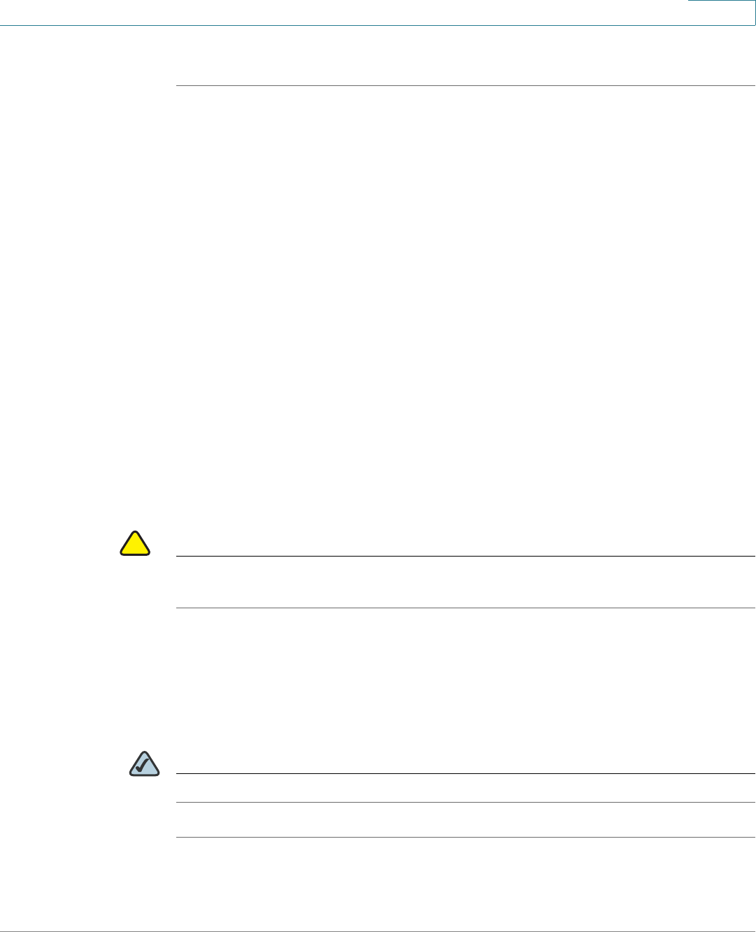
Firewall
Configuring the Content Filtering to Control Access to Internet
Cisco ISA500 Series Integrated Security Appliance Administrator Guide 201
6
STEP 3 Click Save to apply your settings.
Configuring the Content Filtering to Control Access to Internet
The Content Filtering feature provides protection against websites. It blocks or
allows web access based on analysis of its content (URL or URL keywords), rather
than its source or other criteria. It is most widely used on the Internet to filter the
web access.
The Content Filtering policy profile assigned to each zone determines whether to
block or forward the HTTP request from the hosts in the zone. The blocked
request will be logged.
This section includes the following topics:
•Configuring the Content Filtering Policy Profiles, page 201
•Configuring the Website Access Control List, page 203
•Mapping the Content Filtering Policy Profiles to Zones, page 204
•Configuring Advanced Settings, page 204
!
CAUTION Enabling the Web URL Filter service will disable the firewall content filtering
settings.
Configuring the Content Filtering Policy Profiles
A Content Filtering policy profile is used to specify the websites to be blocked or
permitted.
NOTE The security appliance supports up to 16 content filtering policy profiles.
STEP 1 Click Firewall -> Content Filtering -> Content Filtering Policy.
The Content Filtering Policy window opens.
Firewall
Configuring the Content Filtering to Control Access to Internet
Cisco ISA500 Series Integrated Security Appliance Administrator Guide 202
6
STEP 2 To add a content filtering policy profile, click Add.
Other Options: To edit an entry, click Edit. To delete an entry, click Delete.
After you click Add or Edit, the Add/Edit window opens.
STEP 3 Enter the following information:
•Policy Profile: Enter a descriptive name for the content filtering policy
profile.
•Description: Enter a brief message to describe the content filtering policy
profile.
STEP 4 In the Website Access Control List area, specify the whitelist and blacklist of
websites that you want to permit or block. For complete details, see Configuring
the Website Access Control List, page 203.
STEP 5 In the For URLs not Specified Above area, specify the action how to deal with the
websites that are not specified in the whitelist or blacklist.
•Permit Them: If you choose this option, all websites not specified in the list
are permitted.
•Deny Them: If you choose this option, all websites not specified in the list
are blocked.
STEP 6 Click OK to save your settings.
STEP 7 Click Save to apply your settings.
NOTE Next Steps:
•To map the content filtering policy profile to zones, go to the Policy Profile
& Zone Mapping page. See Mapping the Content Filtering Policy Profiles
to Zones, page 204.
•To configure advanced content filtering settings, go to the Advanced
Settings page. See Configuring Advanced Settings, page 204.

Firewall
Configuring the Content Filtering to Control Access to Internet
Cisco ISA500 Series Integrated Security Appliance Administrator Guide 203
6
Configuring the Website Access Control List
The whitelist and blacklist defines the websites that you want to permit or block.
Up to 32 websites can be defined for each content filtering policy profile.
STEP 1 To add a website access rule in the list, click Add.
Other Options: To edit an entry, click Edit. To delete an entry, click Delete. To
delete all entries, click Delete All.
After you click Add or Edit, the Add/Edit window opens.
STEP 2 Enter the following information:
•Enable Content Filter URL: Click On to enable the access control rule, or
click Off to create only the access control rule.
•URL: Enter the domain name or URL keyword of a website that you want to
permit or block.
•Match Type: Specify how to match up with this rule:
-Domain: If you choose this option, permit or block the HTTP access of a
website that fully matches up with the domain you entered in the URL
field.
For example, if you enter yahoo.com in the URL field, then it can match up
with the website such as http://*.yahoo.com/*, but cannot match up with
the website such as http://*.yahoo.com.uk/*.
-Keyword: If you choose this option, permit or block the HTTP access of
a website that contains the keyword you entered in the URL field.
For example, if you enter yahoo in the URL field, then it can match up with
the websites such as www.yahoo.com, tw.yahoo.com,
www.yahoo.com.uk, and www.yahoo.co.jp.
•Action: Choose Permit to permit the access, or choose Block to block the
access.
STEP 3 Click OK to save your settings.

Firewall
Configuring the Content Filtering to Control Access to Internet
Cisco ISA500 Series Integrated Security Appliance Administrator Guide 204
6
Mapping the Content Filtering Policy Profiles to Zones
Use the Policy Profile & Zone Mapping page to map the content filtering policy
profile to each zone.
STEP 1 Click Firewall -> Content Filtering -> Policy Profile & Zone Mapping.
The Policy Profile & Zone Mapping window opens.
STEP 2 Click On to enable the content filtering feature, or click Off to disable it.
STEP 3 In the Policy Profile & Zone Mapping List area, choose the policy profile used for
each zone. By default, the Default_Profile that permits all web access is selected
for all predefined and new zones.
STEP 4 Click Save to apply your settings. .
Configuring Advanced Settings
STEP 1 Click Firewall -> Content Filtering -> Advanced Settings.
The Advanced Settings window opens.
STEP 2 Enter the following information:
•Specify HTTP port for the filtering (default: 80): Enter the port number that
is used for content filtering. The default is 80.
For example, if you permit the HTTP access to the website http://
www.ABcompanyC.com and set the HTTP port to 80. The access to http://
www.ABcompanyC.com:8080 will be blocked.
•Web Components: You can block web components like Proxy, Java,
ActiveX, and Cookies. By default, all of them are permitted.
-Proxy: Check the box to block proxy servers, which can be used to
circumvent certain firewall rules and thus present a potential security
gap.
-Java: Check the box to block applets from being downloaded from
internet sites.
-ActiveX: Check the box to prevent ActiveX controls from being
downloaded via Internet Explorer.

Firewall
Configuring the MAC Filtering to Permit or Block Traffic
Cisco ISA500 Series Integrated Security Appliance Administrator Guide 205
6
-Cookies: Check the box to block cookies, which typically contain
sessions.
•When a web page is blocked: Choose one of the following actions when a
web page is blocked:
-Use the default blocked page: Use the default blocked page if a web
page is blocked. The default blocked page will display a message such
as “Access of this website is blocked due to security policy
configurations on the security appliance”. You can edit the message in
the Block Message field.
-Redirect to this URL: Enter the URL to be redirected if a web page is
blocked.
STEP 3 Click Save to apply your settings.
Configuring the MAC Filtering to Permit or Block Traffic
The MAC filtering feature can permit and deny network access from specific
devices through the use of MAC address list. The firewall MAC filtering settings
apply for all traffic except the traffic for Intra-VLAN and Intra-SSID.
STEP 1 Click Firewall -> MAC Filtering -> MAC Filtering.
The MAC Filtering window opens.
STEP 2 Click On to enable the MAC Filtering feature, or click Off to disable it.
STEP 3 If you enable MAC Filtering, specify the MAC filtering policy:
•Block and Accept the rest: If you choose this option, the MAC addresses in
the table are blocked and all other MAC addresses not included in the table
are permitted.
•Accept and Block the rest: If you choose this option, only the MAC
addresses in the table are permitted and all other MAC addresses not
included in the table are blocked.
STEP 4 Specify the list of MAC addresses. To add a MAC address to the table, click Add.
To edit an entry, click Edit. To delete an entry, click Delete. To delete all selected
entries, check the boxes of multiple entries and click Delete Selection.

Firewall
Configuring the IP/MAC Binding to Prevent Spoofing
Cisco ISA500 Series Integrated Security Appliance Administrator Guide 206
6
For example, if you click Add, the MAC Filtering - Add/Edit window opens. Select
the MAC address object from the MAC Address drop-down list, and then click
OK.
If the MAC address object you want is not in the list, choose Create New Address
to create a new MAC Address object. To maintain the MAC Address objects, go to
the Networking -> Address Object Management page. See Address
Management, page 152.
STEP 5 Click Save to apply your settings.
Configuring the IP/MAC Binding to Prevent Spoofing
The IP/MAC binding feature allows the traffic only when the host has an IP address
that matches up with a specified MAC address. By requiring the gateway to
validate the source traffic’s IP address with the unique MAC address of device,
please ensure that traffic from the specified IP address is not spoofed. If a violation
(the traffic’s source IP address doesn’t match up with the expected MAC address
having the same IP address) occurs, the packets will be dropped and can be
logged for diagnosis.
STEP 1 Click Firewall -> MAC Filtering -> IP/MAC Binding.
The IP/MAC Binding window opens.
STEP 2 To add an IP/MAC binding rule, click Add.
Other options: To edit an entry, click Edit. To delete an entry, click Delete. To
delete all selected entries, check the boxes of multiple entries and click Delete
Selection.
After you click Add or Edit, the IP/MAC Binding - Add/Edit window opens.
STEP 3 Enter the following information:
•Name: Enter a descriptive name for the IP/MAC binding rule.
•MAC Address: Choose an existing MAC address object. If the MAC address
object you want is not in the list, choose Create a MAC to add a new MAC
address object. To maintain the MAC address objects, go to the Networking
-> Address Object Management page. See Address Management,
page 152.

Firewall
Configuring the Attack Protection
Cisco ISA500 Series Integrated Security Appliance Administrator Guide 207
6
•IP Address: Choose an existing IP address object that you want to bind with
the selected MAC address. If the IP address object you want is not in the list,
choose Create an IP Address to add a new IP address object. To maintain
the IP address objects, go to the Networking -> Address Object
Management page. See Address Management, page 152.
•Log Dropped Packets: Choose Enable to log all packets that are dropped.
Otherwise, choose Disable.
STEP 4 Click OK to save your settings.
STEP 5 Click Save to save your settings.
Configuring the Attack Protection
Use the Attack Protection page to specify how to protect your network against
common types of attacks including discovery, flooding, and echo storms.
STEP 1 Click Firewall -> Attack Protection.
The Attack Protection window opens.
STEP 2 In the WAN Security Checks area, enter the following information:
•Block Ping to WAN interface: Check the box to prevent attackers from
discovering your network through ICMP Echo (ping) requests. We
recommend that you disable this feature only if you need to allow the
security appliance to respond to pings for diagnostic purposes.
•Enable Stealth Mode: Check the box to prevent the security appliance from
responding to incoming connection requests from the WAN. In Stealth Mode,
your security appliance does not respond to blocked inbound connection
requests, and your network is less susceptible to discovery and attacks.
•Block TCP Flood: Check this box to drop all invalid TCP packets. This feature
protects your network from a SYN flood attack, in which an attacker sends a
succession of SYN (synchronize) requests to a target system. It blocks all
TCP SYN flood attackes (200 packets per seconds) from the WAN
interfaces.
STEP 3 In the LAN Security Checks section, enter the following information:

Firewall
Configuring the Attack Protection
Cisco ISA500 Series Integrated Security Appliance Administrator Guide 208
6
•Block UDP Flood: Check the box to prevent the security appliance from
accepting more than 200 simultaneous, active UDP connections per second
from a single computer on the LAN.
STEP 4 In the Firewall Settings area, enter the following information:
•Block ICMP Notification: Check the box to silently block without sending an
ICMP notification to the sender. Some protocols, such as MTU Path
Discovery, require ICMP notifications.
•Block Fragmented Packets: Check the box to block fragmented packets
from Any zone to Any zone.
•Block Multicast Packets: Check the box to block multicast packets. By
default, the firewall blocks all multicast packets. This feature has higher
priority than the firewall access rules, which means that the firewall access
rules that permit the multicast traffic will be overrided if you enable this
feature.
STEP 5 In the DoS Attacks area, enter the following information:
•SYN Flood Detect Rate (max/sec): Enter the maximum number of SYN
packets per second that will cause the security appliance to determine that
a SYN Flood Intrusion is occurring. Enter a value from 0 to 10000 SYN
packets per second. A value of zero indicates that the SYN Flook Detect
feature is disabled.
•Echo Storm (ping pkts./sec): Enter the number of pings per second that will
cause the security appliance to determine that an echo storm intrusion event
is occurring. Enter a value from 0 to 10000 ping packets per second. A value
of zero indicates that the Echo Storm feature is disabled.
•ICMP Flood (ICMP pkts./sec): Enter the number of ICMP packets per
second, including PING packets, that will cause the security appliance to
determine that an ICMP flood intrusion event is occurring. Enter a value from
0 to 10000 ICMP packets per second. A value of zero indicates that the IGMP
Flood feature is disabled.
STEP 6 Click Save to apply your settings.
Firewall
Configuring the Application Level Gateway
Cisco ISA500 Series Integrated Security Appliance Administrator Guide 209
6
Configuring the Application Level Gateway
The security appliance can function as an Application Level Gateway (ALG) to
allow certain NAT un-friendly applications (such as SIP or H.323) to operate
properly through the security appliance.
If Voice-over-IP (VoIP) is used in your organization, you should enable the H.323
ALG or SIP ALG to open the ports necessary to enable the VoIP through your voice
device. The ALGs are created to work in a NAT environment to maintain the
security for privately addressed conferencing equipment protected by your voice
device.
You can use both H.323 and SIP ALGs at the same time, if necessary. To determine
which ALG to use, consult the documentation for your VoIP devices or
applications.
STEP 1 Click Firewall -> Application Level Gateway.
The Application Level Gateway window opens.
STEP 2 Enter the following information:
•SIP Protocol Support: SIP ALG can rewrite the information within the SIP
messages (SIP headers and SDP body) to make signaling and audio traffic
between the client behind NAT and the SIP endpoint possible. Check this
box to allow the SIP sessions to pass through the security appliance, or
uncheck this box to block the SIP sessions.
NOTE Enable SIP ALG when voice devices such as UC 500, UC 300, or SIP
phones are connected to the network behind the security appliance.
•H323 Support: H.323 is a standard teleconferencing protocol suite that
provides audio, data, and video conferencing. It allows for real-time point-to-
point and multipoint communication between client computers over a
packet-based network that does not provide a guaranteed quality of
service. Check this box to allow the H.323 sessions to pass through the
security appliance, or uncheck this box to block the H.323 sessions.
STEP 3 Click Save to apply your settings.

7
Cisco ISA500 Series Integrated Security Appliance Administrator Guide 210
Security Services
This chapter describe how to configure the UTM security services to provide the
Internet threat protection.
•Managing the Security Services, page 210
•Intrusion Prevention Service, page 214
•Anti-Virus, page 220
•Email Reputation Filter, page 224
•Web URL Filter, page 226
•Web Reputation Filter, page 230
•Network Reputation, page 231
To access the Security Services pages, click Security Services in the left hand
navigation pane.
Managing the Security Services
This section includes the following topics:
•About the Security Services, page 211
•Security License, page 212
•Priority of Security Services, page 212
•Managing the Security Services, page 212
•Viewing the Security Service Reports, page 214

Security Services
Managing the Security Services
Cisco ISA500 Series Integrated Security Appliance Administrator Guide 211
7
About the Security Services
The security services activated by the security license are listed in the following
table.
Security Services Description
Intrusion
Prevention System
The Intrusion Prevention System (IPS) service can protect
the zones for a given set of categories. IPS monitors
network traffic for malicious or unwanted behaviors on
the security appliance and can react, in real-time, to block
or prevent those activities. For more information, see
Intrusion Prevention Service, page 214.
Anti-Virus The Anti-Virus service prevents network threats over a
multitude of protocols including HTTP, FTP, POP3, SMTP,
CIFS, NETBIOS, and IMAP. For more information, see Anti-
Virus, page 220.
Email Reputation
Filter
The Email Reputation Filter service detects the email
sender’s reputation score. If the reputation score is below
a threshold, then the email is blocked or tagged as SPAM
or SUSPECT SPAM. For more information, see Email
Reputation Filter, page 224.
Web URL Filter The Web URL Filter service provides protection against
URL categories. For more information, see Web URL
Filter, page 226.
Web Reputation
Filter
The Web Reputation Filter service detects threats based
on a web page’s reputation score. Web pages with
reputation scores below a specific threshold are
considered threats and blocked. For more information,
see Web Reputation Filter, page 230.
Network
Reputation
The Network Reputation service checks the source and
destination address of each packet against the address
blacklist to determine whether to proceed or drop the
packet. For more information, see Network Reputation,
page 231.
Security Services
Managing the Security Services
Cisco ISA500 Series Integrated Security Appliance Administrator Guide 212
7
Security License
The security services are licensable. The security license is valid for one year or
three years depending on the bundle type. By default, the security appliance
comes with a one year bundle license for all security services. To renew the
security license before it expires, go to the Device Management -> License
Management page. See Managing the Security License, page 307.
Priority of Security Services
Multiple security services can work simultaneously to protect your network. If you
enable both the Web URL Filter and Web Reputation Filter services, the whitelist
and blacklist of websites that you defined in the Web URL Filter settings cannot
override the Web Reputation Filter settings.
For example, a website is permitted by the Web URL Filter setting, but it has
reputation score lower than the web reputation threshold, the connection to this
website will be blocked even if it is in the whitelist, unless you change the web
reputation threshold.
Managing the Security Services
Use the Dashboard page to view the status of the security license, enable or
disable the security services, and check new updates for all signature-based
security services.
!
CAUTION Enabling the security services consumes additional system resources and may
impact the system performance. Go to the Status -> Dashboard page to view the
CPU and memory utilization. To conserve the system resources, disable the
security services when they are no longer needed.
STEP 1 Click Security Services -> Dashboard.
The Dashboard window opens.
STEP 2 In the License Status area, check the expiration date for the security license. If the
security license expires, go to the Device Management -> License Management
page to renew the license.
STEP 3 In the Settings Summary area, you can perform the following tasks:
Security Services
Managing the Security Services
Cisco ISA500 Series Integrated Security Appliance Administrator Guide 213
7
•To enable a security service, check the box in the Enable column. By default,
only the Network Reputation service is enabled.
NOTE If you enable the IM & P2P Blocking service, it will enable both the IPS
service and the IM & P2P Blocking settings. If you enable the IPS
(Signature) service, it will enable both the IPS service and the IPS
Policy and Protocol Inspection settings. Disabling the IM & P2P
Blocking or IPS (Signature) service will not disable the IPS service.
When both of them are disabled, the IPS service will be disabled.
•To configure the settings for a security service, click the Configure botton.
•For the signature-based security services, such as Anti-Virus and IPS, click
Check for Updates Now to check for new signatures from the Cisco server.
The date and time of the last check are displayed in the Last Check column.
When the signature file is upated successfully, the date and time of the last
successful update are displayed in the Last Update column.
If a new signature file is available, the new signature file will be downloaded
to your local flash partition. The registered CCO account is required to log
into the Cisco server to download the signature file. To configure your CCO
account, go to the Device Management -> CCO Account page. See
Configuring the CCO Account, page 331.
NOTE Email Reputation Filter, Web URL Filter, and Web Reputation Filter are
reputation-based services, clicking the Check for Updates Now
button will not check for any new udpate.
STEP 4 In the External Web Proxy Settings area, enter the following information:
•Web Proxy: Click On to support such as Scansafe and third party outbound
web proxies, or click Off to disable it.
NOTE When the external web proxy is enabled, the Firewall, QoS, Web URL
Filter, and Web Reputation Filter settings will not work or be skipped
for HTTP traffic.
•Redirected Web Proxy IP: Enter the IP address of the external web proxy
used to redirect the HTTP traffic.

Security Services
Intrusion Prevention Service
Cisco ISA500 Series Integrated Security Appliance Administrator Guide 214
7
•Redirected HTTP Port List: Specify the number of the ports used to
redirect the HTTP traffic. To add an entry, click Add. To edit an entry, click
Edit. To delete an entry, click Delete.
STEP 5 Click Save to apply your settings.
Viewing the Security Service Reports
After you enable and configure the security services, you can enable the
corresponding reports for these services to analyze the security performance.
For example, if the Web URL Filter and Web Reputation Filter services are enabled
on your security appliance, you can enable the Web Security Blocked Report to
view the total number of web access requests processed and the total number of
websites blocked since these services were enabled, in last seven days, or in one
day. A graph is provided to show the total number of web access requests
processed and the total number of websites blocked by day for the last seven
days.
For more information about the security service reports, go to the Status ->
Report -> Security Services page. See Reports of Security Services, page 87.
Intrusion Prevention Service
The Intrusion Prevention Service (IPS) feature can protect the zones for a given set
of categories. IPS monitors network traffic for malicious or unwanted behavior on
the device and can react, in real-time, to block or prevent those activities.
When an attack is detected, offending packets are dropped or alerts are logged
depending on the administrative settings, but all other traffic is unaffected. Unlike
traditional firewalls, IPS makes access control decisions based on application
content, rather than IP address or ports.
!
CAUTION Enabling IPS consumes additional system resources and may impact the system
performance. Go to the Status -> Dashboard page to view the CPU and memory
utilizations. To conserve the system resources, disable the IPS service when it is no
longer needed.

Security Services
Intrusion Prevention Service
Cisco ISA500 Series Integrated Security Appliance Administrator Guide 215
7
This section includes the following topics:
•General IPS Settings, page 215
•Configuring the IPS Policy and Protocol Inspection, page 216
•Blocking the Instant Messaging and Peer-to-Peer Applications,
page 218
General IPS Settings
Use the IPS Setup page to enable or disable the IPS service, choose the security
zones you want to protect, update the IPS signatures, and view the IPS signature
status and logs.
STEP 1 Click Security Services -> IPS -> IPS Setup.
The IPS Setup window opens.
STEP 2 Click On to enable IPS, or Click Off to disable IPS.
STEP 3 Specify the zones to block the intrusion for incoming traffic from the selected
zones:
•WAN zone: Choose this option to block the intrusion for incoming traffic from
the WAN zone. This is the default setting.
•WAN + VPN zone: Choose this option to block the intrusion for incoming
traffic from both WAN and VPN zones.
•All zones: Choose this option to block the intrusion for the incoming traffic
from all zones.
STEP 4 In the IPS Status area, you can perform the following tasks:
•IPS Signatures: Displays the status of IPS signature file, including the
expiration date of the security license, the name of the signature file, and the
date and time of your last signature update.
•View IPS Logs: IPS logs a message if an attack is detected. Click this button
to view all IPS log messages.
•Email Alert Setting: IPS sends an alert message to the specified email
account if an attack hits the email alert threshold. Click this link to see the
email alert settings for IPS Alert events.

Security Services
Intrusion Prevention Service
Cisco ISA500 Series Integrated Security Appliance Administrator Guide 216
7
To send alert emails for IPS Alert events, you first need to enable the IPS
Alert feature and configure the email account settings, see Configuring the
Email Alert Settings, page 316. And then configure the IPS Policy and
Protocol Inspection settings and/or the IM and P2P Blocking settings, see
Configuring the IPS Policy and Protocol Inspection, page 216 and
Blocking the Instant Messaging and Peer-to-Peer Applications,
page 218.
STEP 5 The IPS service uses the signatures to identify the attacks in progress. You can
manually or automatically update the IPS signatures.
•Automatic Signature Updates: Click On to automatically update the IPS
signatures periodically if a new signature file is available, or click Off to
disable it.
-User Name: The user name of your registered CCO account used to
download the IPS signature file. To configure the CCO account, click Edit
Account Setting.
-Update: Click this button to immediately update the IPS signatures if a
new signature file is available. The new signature file will be downloaded
from the Cisco server and saved on the flash partition of your device.
•Manual Signature Updates: To manually update the IPS signatures, you first
need to download the latest signature file from the Cisco server to your local
PC. The user name and password of your registered CCO account are
required to log into the Cisco server. Then click Browse to locate and select
the signature file from your local PC, and click Upload.
STEP 6 Click Save to apply your settings.
Configuring the IPS Policy and Protocol Inspection
The IPS Policy protects the network against threats such as Denial-of-Service
attacks, malware, and backdoor exploits. The Protocol Inspection detects
suspicious behavior and attacks on various types of protocols.
STEP 1 Click Security Services -> IPS -> IPS Policy & Protocol Inspection.
The IPS Policy and Protocol Inspection window opens. The IPS categories and
protocols supported on the security appliance are listed in the IPS table.
STEP 2 Enter the following information:
Security Services
Intrusion Prevention Service
Cisco ISA500 Series Integrated Security Appliance Administrator Guide 217
7
•IPS (Signature) Enable: If you enable IPS, click On to enable the IPS Policy
and Protocol Inspection settings.
•View IPS Category Items: Allows you to view the signatures under a
specific IPS category or protocol. For example, if you choose DoS, only the
signatures under the DoS category are displayed. To display all signatures,
choose All.
•Search by IPS Signature ID: Allows you to view a specific signature by
searching the signature ID. Enter the signature ID in this field, and then click
Search. To display all categories and protocols, click Reset.
•Expand/Collapse: To expand the signatures under a category, click the +
button next to the category heading. To hide the signatures, click the - button.
NOTE To get the definition of the signatures, go to http://tools.cisco.com/
security/center/search.x?search=Signature to check the Small
Business IPS signature definitions by using the Signature ID or other
information.
STEP 3 Specify the inspection setting for all signatures under a category or for a signature
only.
•Disabled: Click this option to disable checking the attacks.
•Detect Only: Click this option to check the attacks and to log the event when
an attack is detected. This option is mostly used for troubleshooting
purposes.
•Detect and Prevent: Click this option to check the attacks and to log the
event and drop the packet when an attack is detected.
To log the IPS events, you first need to choose Detect Only or Detect and
Prevent for the IPS categories or IPS signatures, and then go to the Device
Management -> Loggings pages to configure the log settings and log
facilities:
-To save the IPS logs in the lcoal syslog daemon, you need to enable the
Log feature, set the log buffer size and the severity for local log, and then
check the Local Log box for the IPS (signature based) and IPS
(reputation based) log facilities.

Security Services
Intrusion Prevention Service
Cisco ISA500 Series Integrated Security Appliance Administrator Guide 218
7
-To save the IPS logs to the remote syslog server if you have a remote
syslog server support, you need to enable the Log feature, specify the
Remote Log settings, and check the Remote Log boxes for the IPS
(signature based) and IPS (reputation based) log facilities.
For more information about how to configure the log settings and log
facilities, and how to view the logs, see Log Management, page 302.
•Email Alert Threshold: Enter the value of the email alert threshold. When the
hit count is over the email alert threshold, an alert email is sent to the
specified email acount.
To send the IPS alert emails to the specified email accont, you first need to
enable the IPS Alert feature and configure the email account settings, see
Configuring the Email Alert Settings, page 316.
STEP 4 Click Save to apply your settings.
Blocking the Instant Messaging and Peer-to-Peer
Applications
Use the IM & P2P blocking page to block Instant Message (IM) and Peer-to-Peer
(P2P) traffic on the security appliance.
STEP 1 Click Security Services -> IPS -> IM & P2P Blocking.
The IM & P2P Blocking window opens. The supported IM applications are listed in
the IM Blocking table. The supported P2P applications are listed in the P2P
Blocking table.
STEP 2 Enter the following information:
•IM & P2P Blocking Enable: If you enable IPS, click On to enable the IM and
P2P Blocking settings.
•View IM Blocking Item: Allows you to view the signatures under a specific
IM application.
For example, if you choose MSN, only the signatures under the MSN
application are displayed. To display all signatures, choose All.
•View P2P Blocking Item: Allows you to view the signatures under a specific
P2P application.

Security Services
Intrusion Prevention Service
Cisco ISA500 Series Integrated Security Appliance Administrator Guide 219
7
For example, if you choose BitTorrent, only the signatures under the
BitTorrent application are displayed. To display all signatures, choose All.
•Search by Signature ID: Allows you to view a specific signature by
searching the signature ID. Enter the signature ID in this field, and then click
Search. To display all categories, click Reset.
•Expand/Collapse: To expand the signatures under an IM or P2P application,
click the + button. To hide the signatures, click the - button.
STEP 3 Specify the setting for all signatures under an IM or P2P application or for a single
signature:
•Disabled: Choose this option to disable checking attacks.
•Detect Only: Click this option to check the attacks and to log a message
when an attack is detected. This option is mostly used for troubleshooting
purposes.
•Detect and Prevent: Click this option to check the attacks, and to log a
message and drop the packet when an attack is detected.
To log the IPS events, you first need to choose Detect Only or Detect and
Prevent for the IM or P2P applications, and then go to the Device
Management -> Loggings pages to configure the log settings and log
facilities:
-To save the IPS logs in the lcoal syslog daemon, you need to enable the
Log feature, set the log buffer size and the severity for local log, and then
check the Local Log box for the IM/P2P Blocking log facility.
-To save the IPS logs to the remote syslog server if you have a remote
syslog server support, you need to enable the Log feature, specify the
Remote Log settings, and check the Remote Log box for the IM/P2P
Blocking log facility.
For more information about how to configure the log settings and log
facilities, and how to view the logs, see Log Management, page 302.
•Email Alert Threshold: Enter the value of the email alert threshold. When the
hit count is over the email alert threshold, an alert email is sent to the
specified email acount.
To send the IPS alert emails to the specified email accont, you first need to
enable the IPS Alert feature and configure the email account settings, see
Configuring the Email Alert Settings, page 316.
Security Services
Anti-Virus
Cisco ISA500 Series Integrated Security Appliance Administrator Guide 220
7
STEP 4 Click Save to apply your settings.
Anti-Virus
The security appliance can scan for viruses over a multitude of protocols including
HTTP, FTP, POP3, SMTP, CIFS, NETBIOS, and IMAP. Because files containing
malicious code and viruses can also be compressed and therefore inaccessible to
conventional anti-virus solutions, the security appliance integrates advanced
decompression technology that automatically decompresses and scans the files
on a per packet basis.
NOTE The Anti-Virus feature supports virus scanning for one layer compressed files in the
zip, gzip, tar, bzip2, and rar2.0 formats.
!
CAUTION Enabling Anti-Virus consumes additional system resources and may impact the
system performance. Go to the Status -> Dashboard page to view the CPU and
memory utilizations. To conserve the system resources, disable the service when
it is no longer needed.
This section includes the following topics:
•Configuring the Anti-Virus, page 220
•Configuring the Email Notification, page 223
•Configuring the HTTP Notification, page 224
Configuring the Anti-Virus
STEP 1 Click Security Services -> Anti-Virus -> General Settings.
The General Settings window opens.
STEP 2 Enter the following information:
•Enable Anti-Virus: Click On to enable Anti-Virus, or click Off to disable it.

Security Services
Anti-Virus
Cisco ISA500 Series Integrated Security Appliance Administrator Guide 221
7
•Select which zone to scan for virus: Specify the zones to scan the viruses
for the incoming traffic from the selected zones:
-WAN zone: Choose this option to scan the viruses only for the traffic from
WAN zone to all other zones.
-WAN + VPN zone: Choose this option to scan the viruses for the traffic
from both WAN and VPN zones to all other zones.
-All zones: Choose this option to scan the viruses for the incoming traffic
from all zones. This is the default setting.
STEP 3 Specify the following settings for the protocols that you want to scan for viruses:
•Enable: Check the box in this column to scan for the viruses for the protocol.
•Log: Check the box in this column to log the event when viruses are
detected.
To log the Anti-Virus events, you first need to check the Log box for the
protocols, and then go to the Device Management -> Loggings pages to
configure the log settings and log facilities:
-To save the Anti-Virus logs in the lcoal syslog daemon, you need to enable
the Log feature, set the log buffer size and the severity for local log, and
then check the Local Log box for the Anti-Virus log facility.
-To save the Anti-Virus logs to the remote syslog server if you have a
remote syslog server support, you need to enable the Log feature,
specify the Remote Log settings, and check the Remote Log box for the
Anti-Virus log facility.
For more information about how to configure the log settings and log
facilities, and how to view the logs, see Log Management, page 302.
•Action: Specify the preventive action for each protocol when viruses are
detected.
-None: No action is required when viruses are detected.
-Alert: Sends an alert email to the specified email account when viruses
are detected for the SMTP or POP3 protocol, or sends an alert message
to the user when using the HTTP protocol to download the files
containing viruses.
-Drop Connection: Drops the connection when viruses are detected.
-Destruct File: Destructs the file when viruses are detected.
Security Services
Anti-Virus
Cisco ISA500 Series Integrated Security Appliance Administrator Guide 222
7
The available preventive actions for each protocol are listed in the following
table.
STEP 4 Because the compressed files in .bz2 and .rar formats can be reassembled and
uncompressed after collecting the whole packets, you need to specify the
maximum size for scanning the viruses for them. Enter the value in Kilobytes in the
Max Scan File Compression File Size field. When the size of the detected
compressed file is larger than this setting, the compressed file will not be
detected.
STEP 5 Click Save to apply your settings.
NOTE Next Steps:
•If you select Alert or Alert+Descruct File for SMTP or POP3 protocol, go to
the Email Notification page to configure the email notification settings. See
Configuring the Email Notification, page 223.
•If you select Alert or Alert+Drop Connection for HTTP protocol, go to the
HTTP Notification page to configure the HTTP notification settings. See
Configuring the HTTP Notification, page 224.
Protocols Preventive Actions
HTTP None, Alert, Alert+Drop Connection
SMTP None, Alert, Alert+Destruct File
FTP None, Drop Connection
POP3 None, Alert, Alert+Destruct File
IMAP None, Drop Connection
NETBIOS None, Drop Connection
CIFS None, Drop Connection
Security Services
Anti-Virus
Cisco ISA500 Series Integrated Security Appliance Administrator Guide 223
7
Configuring the Email Notification
Use the Email Notification page to configure the tag and content message that are
displayed in the alert email. The subject of the alert email will be tagged such as
[Virus] Email Subject.
If you select Alert for SMTP or POP3 protocol, when viruses are detected in the
email, the original email and an alert email are sent to the email receiver.
If you select Alert + Descruct File for SMTP or POP3 protocol, when viruses are
detected in the email, the original email is destructed and an alert email is sent to
the email receiver.
STEP 1 Click Security Services -> Anti-Virus -> Email Notification.
The Email Notification window opens.
STEP 2 Enter the following information:
•Email Alert Status: Shows if the Alert or Alert+Destruct File action is
selected or not for SMTP or POP3 protocol.
•From Email Address: The email address of the SMTP email account to send
the alert email.
•SMTP Server: The IP address or Internet name of the SMTP server.
•SMTP Authentication: Shows if the SMTP authentication is enabled or
disabled.
NOTE The above email account settings are read only. They are used to
send the alert emails to the original email receiver. Click the Email
Alert Setting link to configure the email account settings. For more
information, see Configuring the Email Alert Settings, page 316.
•Mail Tag: Enter the tag that shows in the alert email ’s subject. The tag will
insert to the alert email subject in the [Tag] Email Subject format.
•Mail Content: Enter the content that appears in the alert email.
STEP 3 Click Save to apply your settings.
Security Services
Email Reputation Filter
Cisco ISA500 Series Integrated Security Appliance Administrator Guide 224
7
Configuring the HTTP Notification
Use the HTTP Notification page to configure the alert message if viruses are
detected when using the HTTP protocol to download the files containing viruses.
If you select Alert , an alert message is sent to the user when viruses are detected.
If you select Alert+Drop Connection, the connection is dropped and an alert
message is sent to the user when viruses are detected.
STEP 1 Click Security Services -> Anti-Virus -> HTTP Notification.
The HTTP Notification window opens.
STEP 2 Enter the alert message in the HTTP Content field.
STEP 3 Click Save to apply your settings.
Email Reputation Filter
The Email Reputation Filter feature detects the email sender’s reputation score.
The reputation scores range from -10 (bad) to +10 (good). An email is classified as
SPAM if the sender’s reputation is below the SPAM threshold, or is classified as
SUSPECT SPAM if the sender’s reputation is between the SPAM threshold and
SUSPECT SPAM threshold. An email is not classified as SPAM if the sender’s
reputation is above the SUSPECT SPAM threshold.
!
CAUTION Enabling Email Reputation Filter consumes additional system resources and may
impact the system performance. Go to the Status -> Dashboard page to view the
CPU and memory utilizations. To conserve the system resources, disable the
service when it is no longer needed.
STEP 1 Click Security Services -> Anti-Spam.
The Email Reputation Filter window opens.
STEP 2 Enter the following information:

Security Services
Email Reputation Filter
Cisco ISA500 Series Integrated Security Appliance Administrator Guide 225
7
•Enable Anti-Spam Filter: Click On to enable Email Reputation Filter, or check
Off to disable it.
•SMTP Server Address: Enter the address of the SMTP server.
•Choose Reputation Threshold: Specify the block sensitivity as either
Conservative, Moderate or Aggressive, or as a numerical threshold (Custom).
When the Custom radio button is selected, the drop-down lists next to it are
enabled allowing the threshold values to be entered. The allowable values
for the threshold are integers from -10 to -1 and the value -0.5.
The Email Reputation Filter detects spam emails based on the reputation
score of the sender’s IP address. The sender’s address is the address that
initiated the connection to the SMTP server, not an address within the email
header.
STEP 3 Specify the actions for SPAM and SUSPECT SPAM emails:
•Action for SPAM Is: Choose Block to block the email, or choose TAG to get
the email tagged with [SPAM].
•Action for SUSPECT SPAM Is: Choose Block to block the email, or choose
TAG to get the email tagged with [SUSPECT SPAM].
STEP 4 Choose one of the following actions if the Email Reputation Filter service is
unavailable:
•Do not accept any emails until reputation services are restored (emails
will be delayed): If you choose this option, all emails will be delayed until the
Email Reputation Filter service is restrored.
•Deliver all emails without checking for spam: If you choose this option, you
can deliver all emails without checking for spam. This is the default setting if
Email Reputation Filter service is unavailable.
STEP 5 Click Save to apply your settings.
Security Services
Web URL Filter
Cisco ISA500 Series Integrated Security Appliance Administrator Guide 226
7
Web URL Filter
The Web URL Filter feature provides protection against URL categories. The Web
URL Filter policy profile assigned to each zone determines whether to block or
forward the HTTP request from the hosts in the zone. The blocked request will be
logged.
!
CAUTION Enabling Web URL Filter consumes additional system resources and may impact
the system performance. Go to the Status -> Dashboard page to view the CPU and
memory utilizations. To conserve the system resources, disable the service when
it is no longer needed.
This section includes the following topics:
•Configuring the Web URL Filter Policy Profiles, page 226
•Mapping the Web URL Filter Policy Profiles to Zones, page 228
•Configuring Advanced Web URL Filter Settings, page 229
Configuring the Web URL Filter Policy Profiles
A Web URL Filter policy profile is used to specify the URL categories to be
blocked.
STEP 1 Click Security Services -> Web URL Filter -> Policy Profile.
The Web URL Filter Policy Profile window opens. The default and custom Web
URL Filter policy profiles are listed in the table.
STEP 2 To add a new Web URL Filter policy profile, click Add.
Other Options: To edit an entry, click Edit. To delete an entry, click Delete. The
default profile cannot be deleted.
After you click Add or Edit, the Add/Edit window opens.
STEP 3 Enter the following information:
•Policy: Enter an unique name for the policy profile.
•Description: Enter a brief message to describe the policy profile.
Security Services
Web URL Filter
Cisco ISA500 Series Integrated Security Appliance Administrator Guide 227
7
•Select URL Categories to Block: Specify the URL categories to be blocked.
To block an URL catetory, check the box. Click Select All to block all
categories, or click Clear All to permit all categories.
STEP 4 If needed, specify the whitelist and blacklist of websites to permit or block
specific websites. For complete details, see Configuring the Whitelist and
Blacklist of Websites, page 227.
If an URL category is blocked (or permited), all websites that belongs to this
category will be blocked (or permited). The whitelist and blacklist of websites
allows you to permit or block the websites against the URL category settings. The
whitelist and blacklist have higher priority than the URL category settings.
For example, if the Sports category is blocked , but you want to permit the
www.espn.com, you can add it to the whitelist.
STEP 5 Click Save to apply your settings.
NOTE Next Steps:
•To map the Web URL Filter policy profile to zones, go to the Zone Mapping
page. See Mapping the Web URL Filter Policy Profiles to Zones,
page 228.
•To configure advanced Web URL Filter settings, go to the Advanced
Settings page. See Configuring Advanced Web URL Filter Settings,
page 229.
Configuring the Whitelist and Blacklist of Websites
Blocking an URL category will block all websites that belong to this category. You
can specify the whitelist and blacklist of websites to permit or block specific
websites against the URL category settings.
STEP 1 In the Define Policy Specify URLs or URL keywords you want to permit or deny
area, click Edit.
The Add/Edit window opens. The URLs and URL keywords specified in the
whitelist and blacklist are displayed in the website access control list.
STEP 2 To add an access control rule for a website, click Add.

Security Services
Web URL Filter
Cisco ISA500 Series Integrated Security Appliance Administrator Guide 228
7
Other Options: To edit an entry, click Edit. To delete an entry, click Delete. To
delete all entries, click Delete All.
After you click Add or Edit, the Add/Edit window opens.
STEP 3 Enter the following information:
•Enable Content Filter URL: Click On to enable the access control rule, or
click Off to create only the access control rule.
•URL: Enter the domain name or URL keyword of a website that you want to
permit or block.
•Match Type: Specify the method for applying this rule:
-Domain: Permit or deny the HTTP access of a website that fully matches
up with the domain name you entered in the URL field.
For example, if you enter yahoo.com in the URL field, then it can match up
with the website such as http://*.yahoo.com/*, but cannot match up with
the website such as http://*.yahoo.com.uk/*.
-Keyword: Permit or deny the HTTP access of a website that contains the
keyword you entered in the URL field.
For example, if you enter yahoo in the URL field, then it can match up with
the websites such as www.yahoo.com, tw.yahoo.com,
www.yahoo.com.uk, and www.yahoo.co.jp.
•Action: Choose Permit to permit the access, or choose Block to block the
access.
STEP 4 Click OK to save your settings.
Mapping the Web URL Filter Policy Profiles to Zones
Use the Zone Mapping page to map the Web URL Filter policy profile to zones. By
default, the Default Profile is assigned to all predefined zones and new zones.
STEP 1 Click Security Services -> Web URL Filter -> Zone Mapping.
The Zone Mapping window opens.
STEP 2 Click On to enable the Web URL Filter feature, or click Off to disable it.

Security Services
Web URL Filter
Cisco ISA500 Series Integrated Security Appliance Administrator Guide 229
7
NOTE Enabling the Web URL Filter service will disable the firewall content filtering
settings.
STEP 3 In the Specify the policy used for each zone area, choose the Web URL Filter
policy profile used for each zone.
STEP 4 Click Save to apply your settings.
Configuring Advanced Web URL Filter Settings
STEP 1 Click Security Services -> Web URL Filter -> Advanced Settings.
The Advanced Settings window opens.
STEP 2 Enter the following information:
•Specify HTTP port for Web URL Filter (default: 80): Enter the port number
that is used for the Web URL Filter settings. The default is 80.
For example, if you permit the HTTP access to the website http://
www.ABcompanyC.com and set the HTTP port to 80. The access to http://
www.ABcompanyC.com:8080 will be blocked.
•Select which Web Components to block: You can block or permit the web
components like Proxy, Java, ActiveX, and Cookies. By default, all of them
are permitted.
-Proxy: Check the box to block proxy servers, which can be used to
circumvent certain firewall rules and thus present a potential security
gap.
-Java: Check the box to block applets from being downloaded from
internet sites.
-ActiveX: Check the box to prevent ActiveX controls from being
downloaded via Internet Explorer.
-Cookies: Check the box to block cookies, which typically contain
session information.
•If Web URL Filter services are unavailable: Specify one of the following
actions if Web URL Filter services are unavailable:
Security Services
Web Reputation Filter
Cisco ISA500 Series Integrated Security Appliance Administrator Guide 230
7
-Block all web traffic until web URL filter services are restored: If you
choose this option, all web traffic will be blocked until the Web URL Filter
services are restored, and displays the default blocked page. The default
blocked page will display a message to remind the user. You can edit the
message in the Block Message field.
-Allow all web traffic until web URL filter services are restored: If you
choose this option, all web traffic will be permitted until the Web URL
Filter services are restored.
•When a web page is blocked: Specify one of the following actions if a web
page is blocked:
-Use the default blocked page: Use the default blocked page if a web
page is blocked. The default blocked page will display a message such
as “Access of this website is blocked due to security policy
configurations on the security appliance”. You can edit the message in
the Block Message field.
-Redirect to this URL: Enter the URL to be redirected if a web page is
blocked.
STEP 3 Click Save to apply your settings.
Web Reputation Filter
The Web Reputation Filter service detects the web threats based on the
reputation score of a web page. Reputation scores range from -10 (bad) to +10
(good). Web pages with reputation scores below a specific threshold are
considered threats and blocked.
!
CAUTION Enabling Web Reputation Filter consumes additional system resources and may
impact the system performance. Go to the Status -> Dashboard page to view the
CPU and memory utilizations. To conserve the system resources, disable the
service when it is no longer needed.
STEP 1 Click Security Services -> Web Reputation Filter.
The Web Reputation Filter window opens.

Security Services
Network Reputation
Cisco ISA500 Series Integrated Security Appliance Administrator Guide 231
7
STEP 2 Enter the folllowing information:
•Enable Web Threat Filter: Click On to enable the Web Reputation Filter
feature, or click Off to disable it.
•Choose Reputation Threshold: If you enable the Web Reputation Filter
feature, specify the block sensitivity as either Conservative, Moderate, or
Aggressive, or as a numerical threshold (Custom). The threshold values for
Conservative, Moderate, or Aggressive option are predefined and
uneditable. If you want to customize a threshold value, click Custom and
choose the threshold value from the drop-down list. The available values for
the threshold are integers from -10 to -1 and the value -0.5.
STEP 3 Specify one of the following actions if the Web Reputation Filter services are
unavailable:
•Block all web traffic until the web reputation filter services are restored:
If you choose this option, all web traffic will be blocked until the Web
Reputation Filter services are restored, and the default blocked page will
used. The default blocked page displays a message to remind the user. You
can edit the message in the Block Message field.
•Allow all web traffic until the web reputation filter services are restored:
If you choose this option, all web traffic will be allowed until the Web
Reputation Filter services are restored.
STEP 4 Click Save to apply your settings.
Network Reputation
Network Reputation checks the source and destination address of each packet
against the address blacklist to determine whether to proceed or to drop the
packet. The blacklist data is automatically updated in its entirety a few times per
day.
NOTE No configuration is needed for the Network Reputation feature. You only need to
enable or disable this feature from the Security Services -> Dashboard page.

8
Cisco ISA500 Series Integrated Security Appliance Administrator Guide 232
VPN
This chapter describes how to configure Virtual Private Networks (VPN) that
allowing other sites and remote workers to access your network resources. It
includes the following sections:
•About VPN, page 232
•Configuring the Cisco IPSec VPN Server, page 233
•Configuring the Cisco IPSec VPN Client, page 238
•Configuring the Site-to-Site VPN, page 246
•Configuring the SSL VPN, page 257
•Configuring the L2TP Server, page 266
•Configuring the VPN Passthrough, page 268
•Viewing the VPN Status, page 268
To access the VPN pages, click VPN in the left hand navigation pane.
About VPN
A VPN provides a secure communication channel (“tunnel”) between two gateway
routers or between a remote PC and a gateway router. The security appliance
provides the following VPN solutions:
•Cisco IPSec VPN Server: The Cisco IPSec VPN Server feature allows the
security appliance to act as a head-end device in remote access VPNs. The
server pushes the security policies to remote clients, so that remote clients
have up-to-date policies in place before establishing the connections. The
server can also terminate the VPN tunnels initiated by the clients. This
flexibility allows mobile and remote users to access critical data and
applications on corporate Intranet. See Configuring the Cisco IPSec VPN
Server, page 233.
VPN
Configuring the Cisco IPSec VPN Server
Cisco ISA500 Series Integrated Security Appliance Administrator Guide 233
8
•Cisco IPSec VPN Client: The Cisco IPSec VPN Client feature minimizes the
configuration requirements at remote locations by allowing the security
appliance to work as a Cisco VPN hardware client to receive the security
policies upon the VPN tunnel from a remote Cisco IPSec VPN Server. See
Configuring the Cisco IPSec VPN Client, page 238.
•Site-to-Site VPN: The Site-to-Site VPN tunnel connects two routers to
secure traffic between two sites that are physically separated. See
Configuring the Site-to-Site VPN, page 246.
•SSL VPN: The SSL VPN feature allows remote users to access the
corporate network by using the Cisco AnyConnect VPN Client. Remote
access is provided through a SSL VPN gateway. See Configuring the SSL
VPN, page 257.
•L2TP: L2TP allows remote clients to use a public IP network to secure
communicate with private corporate network servers. This protocol is
based on the client and server model. See Configuring the L2TP Server,
page 266.
NOTE The security appliance can function as a Cisco IPSec VPN server or as a Cisco
IPSec VPN client, but not both simutaneously. It does not have a default role.
Configuring the Cisco IPSec VPN Server
The Cisco IPSec VPN Server feature allows remote users to establish the IPSec
VPN tunnels to securely access the corporate network resources. It includes the
following sections:
•Cisco VPN Client Compatibility, page 234
•Configuring the Group Policies for Cisco IPSec VPN Server, page 235
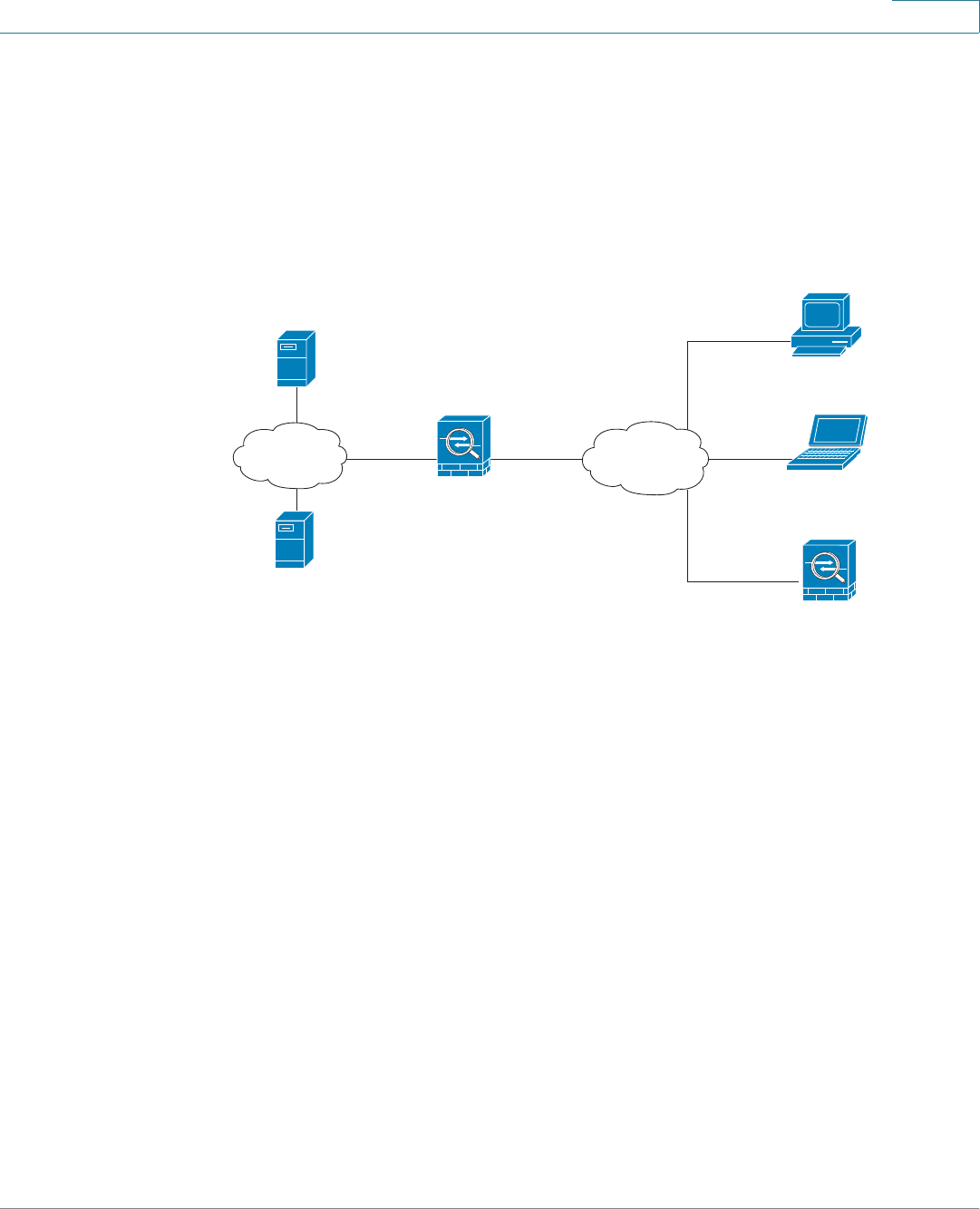
VPN
Configuring the Cisco IPSec VPN Server
Cisco ISA500 Series Integrated Security Appliance Administrator Guide 234
8
Cisco VPN Client Compatibility
The remote client can be a Cisco device that supports the Cisco IPSec VPN Client
feature (a Cisco VPN hardware client) or a PC running the Cisco VPN Client
software (v4.x or 5.x, a Cisco VPN software client).
Figure 6 IPSec Remote Access with a Cisco VPN Client Software or a Cisco
Device as a Cisco VPN Hardware Client
The Cisco VPN Client is an IPSec client software for Windows, Mac, or Linux users.
The Cisco VPN Client is compatible with the following platforms:
•Windows 7 32-bit (x86) and 64-bit ( x64)
•Windows Vista 32-bit (x86) and 64-bit ( x64)
•Windows XP 32-bit (x86) and 64-bit ( x64)
•Mac OS X 10.5 and 10.6
You can find the software installers for Cisco VPN Client on the CD, or download
the software installers from Cisco.com (A registered CCO account is required to
log into the website). For more information about how to download, install, and
configure the Cisco VPN Client software, see http://www.cisco.com/en/US/
products/sw/secursw/ps2308/index.html.
Inside
10.10.10.0
Outside
ISA500
as a Cisco IPSec VPN Server
DNS Server
10.10.10.163
WINS Server
10.10.10.133
Internet
Internal
network Personal Computer
running Cisco VPN Client software
Personal Computer
running Cisco VPN Client software
Cisco Device
as a Cisco VPN hardware client
VPN
Configuring the Cisco IPSec VPN Server
Cisco ISA500 Series Integrated Security Appliance Administrator Guide 235
8
Configuring the Group Policies for Cisco IPSec VPN Server
This section describes how to enable the Cisco IPSec VPN Server feature and
specify the group policies that can be used by the remote clients to establish the
IPSec VPN tunnels.
NOTE The security appliance supports up to 16 group policies for Cisco IPSec VPN
Server.
STEP 1 Click VPN -> Remote User Access -> Cisco IPSec VPN Server.
The Cisco IPSec VPN Server window opens. All existing group policies are listed
in the table.
STEP 2 Click On to enable the Cisco IPSec VPN Server feature and set the security
appliance as a head-end device in remote access VPN, or click Off to disable it.
STEP 3 Specify the group policies that can be used by the remote clients to establish the
IPSec VPN tunnels. To add a group policy, click Add.
Other Options: To edit an entry, click Edit. To delete an entry, click Delete.
After you click Add or Edit, the Cisco IPSec VPN Server - Add/Edit window opens.
STEP 4 In the Basic Settings tab, enter the following information:
•Group Name: Enter the name for the group policy.
•WAN Interface: Choose the WAN interface that the traffic passes through
over the IPSec VPN tunnel.
•Authentication Method: Choose the authentication method.
-Preshare: If you choose this option, enter the desired value that the peer
device must provide to establish a connection in the Password field. The
pre-shared key must be entered exactly the same here and on the remote
clients.
-Certificate: If you choose this option, choose the local certificate and the
peer certificate for authentication. On the remote clients, the selected
local certificate should be set as the peer certificate, and the selected
peer certificate should be set as the local certificate. If the certificates are
not in the list, go to the Device Management -> Certificate
Management page to import the certificates. See Managing the
Certificates for Authentication, page 310.
VPN
Configuring the Cisco IPSec VPN Server
Cisco ISA500 Series Integrated Security Appliance Administrator Guide 236
8
•Mode: The operation mode determines whether the inside hosts relative to
the Cisco VPN hardware client are accessible from the corporate network
over the IPSec VPN tunnel. Specifying a operation mode is mandatory
before making a connection because the Cisco VPN hardware client does
not have a default mode. For more information, see Modes of Operation,
page 240.
-Client: Choose this mode for the group policy that is used for both the PC
running the Cisco VPN Client software and the Cisco device that works
as the Cisco VPN hardware client. In client mode, the server can assign
the IP address to the outside interface of remote clients. To define the
pool range for the clients, enter the starting and ending IP addresses in
the Start IP and End IP fields.
-NEM: Choose this mode for the group policy that is only used for the
Cisco device that works as the Cisco VPN hardware client. The Cisco
VPN hardware client can obtain a private IP address from a DHCP server
over the IPSec VPN tunnel.
•WAN Failover: Click On to enable WAN Failover, or click Off to disable it. If
you enable WAN Failover, the traffic is automatically redirected to the
secondary link when the primary link is down.
NOTE To enable the WAN Failover for Cisco IPSec VPN tunnels, make sure
that the secondary WAN interface was configured and the WAN
redundancy was set to the Loab Balancing or Failover mode.
NOTE The security appliance will automatically update the local WAN
gateway for the VPN tunnel based on the configurations of the backup
WAN link. For this purpose, Dynamic DNS has to be configured
because the IP address will change due to failover, or let the remote
gateway use a dynamic IP address.
STEP 5 In the Zone Access Control tab, you can control the access from the PC running
the Cisco VPN Client software or the private network of the Cisco VPN hardware
client to the zones over IPSec VPN tunnels. Click Permit to permit the access, or
click Deny to deny the access. By default, the access for all zones is permitted.
VPN
Configuring the Cisco IPSec VPN Server
Cisco ISA500 Series Integrated Security Appliance Administrator Guide 237
8
NOTE The VPN access rules that are automatically generated by the Zone Access
Control settings will be added to the firewall access rule table with the
priority higher than the default access rules, but lower than the custom
access rules.
STEP 6 In the Mode Config Settings tab, enter the following information:
•Primary DNS Server: Enter the IP address of the primary DNS server.
•Secondary DNS Server: Enter the IP address of the secondary DNS server.
•Primary WINS Server: Enter the IP address of the primary WINS server.
•Secondary WINS Server: Enter the IP address of the secondary WINS
server.
•Default Domain: Enter the default domain name.
•Backup Server 1/2/3: Enter the IP addresses of backup servers. When the
primary server is down, the client can connect to the backup server. The
backup server 1 has the highest priority and the backup server 3 has the
lowest priority.
NOTE The backup servers that you specified on the Cisco IPSec VPN
Server will be sent to the remote clients when initiating the VPN
connection. The remote clients will cache them.
•Split Tunnel: Click On to enable the split tunneling feature, or click Off to
disable it. Split tunneling allows only the traffic that is specified by the VPN
client routes to corporate resources through the VPN tunnel. If you enable the
split tunneling feature, you need to define the split subnets. To add a subnet,
enter the IP address in the IP filed and and netmask address in the Netmask
filed, and then click Add. To delete a subnet, choose a subnet from the list
and then click Delete.
•Split DNS: Split DNS directs DNS packets in clear text through the VPN
tunnel to domains served by the corporate DNS. To add a domain, enter the
IP address or domain name in the Domain Name filed and then click Add. To
delete a domain, select it from the list and then click Delete.
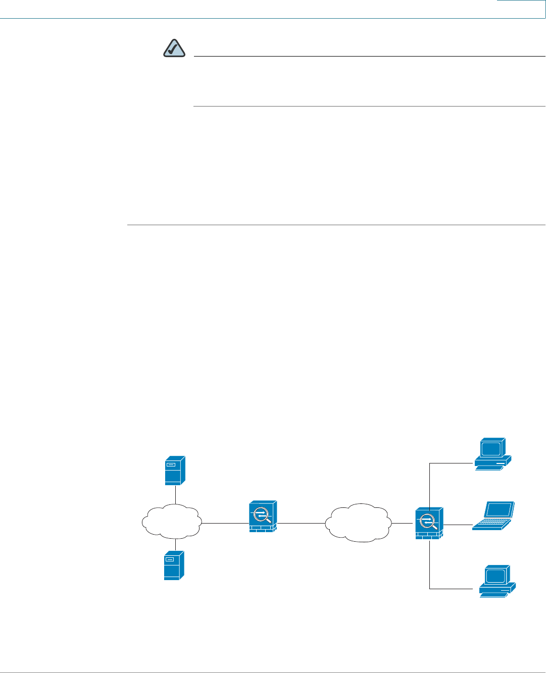
VPN
Configuring the Cisco IPSec VPN Client
Cisco ISA500 Series Integrated Security Appliance Administrator Guide 238
8
NOTE To use Split DNS, you must also enable the split tunneling feature and
specify the domains. The Split DNS feature supports up to 10
domains.
STEP 7 Click OK to save your settings.
STEP 8 Click Save to apply your settings.
STEP 9 To check the status and statistic information for IPSec VPN tunnels, go to the
Session Status -> VPN Table page. See Monitoring the IPSec VPN Status,
page 269.
Configuring the Cisco IPSec VPN Client
The Cisco IPSec VPN Client feature minimizes the configuration requirements at
remote locations by allowing the security appliance to work as a Cisco VPN
hardware client to receive the security policies upon the VPN tunnel from a remote
Cisco IPSec VPN Server. This solution is ideal for remote offices with little IT
support or for large customer premises equipment (CPE) deployments where it is
impractical to configure multiple remote devices individually.
Figure 7 IPSec Remote Access with a Cisco IPSec VPN Server
Inside
10.10.10.0
Outside
Cisco Device
as a Cisco IPSec VPN Server
DNS Server
10.10.10.163
WINS Server
10.10.10.133
Internet
Internal
network
ISA500
as a Cisco IPSec VPN Client
Personal Computer
Personal Computer
Personal Computer
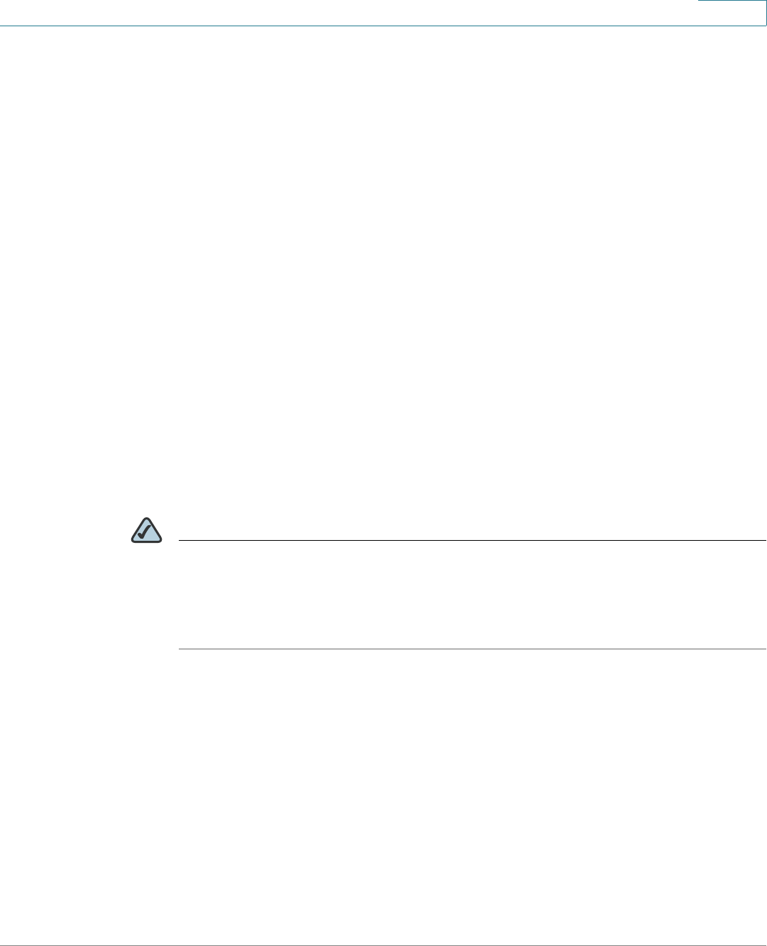
VPN
Configuring the Cisco IPSec VPN Client
Cisco ISA500 Series Integrated Security Appliance Administrator Guide 239
8
This section describes how to configure the Cisco IPSec VPN Client feature. It
includes the following topics:
•Restrictions for Cisco IPSec VPN Client, page 239
•Benefits of the Cisco IPSec VPN Client Feature, page 239
•Modes of Operation, page 240
•General Settings, page 242
•Configuring the Group Policies for Cisco IPSec VPN Client, page 243
Restrictions for Cisco IPSec VPN Client
The Cisco IPSec VPN Client feature requires that the destination peer is a Cisco
ISA500 Series Integrated Security Appliance that works as the Cisco IPSec VPN
Server, or a Cisco IOS router (such as C871, C1801, C1812, C1841, and C2821) or a
Cisco ASA5500 platform that supports the Cisco IPSec VPN Server feature.
The Cisco IPSec VPN Client feature supports configuration of only one destination
peer. If your application requires multiple VPN tunnels, you must manually
configure the IPSec VPN and Network Address Translation/Peer Address
Translation (NAT/PAT) parameters on both client and server.
NOTE If you set the security appliance as a Cisco VPN hardware client, the VPN tunnels
established by Site-to-Site VPN or Cisco IPSec VPN Server are automatically
disconnected. The Cisco IPSec VPN Client feature allows you to create multiple
group polices to connect different servers but only one group policy can be used
to establish the IPSec tunnel with a specified server.
Benefits of the Cisco IPSec VPN Client Feature
•Allows dynamic configuration of end-user policy, requiring less manual
configuration by end users and field technicians, thus reducing errors and
further service calls.
•Allows the provider to change equipment and network configurations as
needed, with little or no reconfiguration of the end-user equipment.
•Provides for centralized security policy management.
•Enables large-scale deployments with rapid user provisioning.

VPN
Configuring the Cisco IPSec VPN Client
Cisco ISA500 Series Integrated Security Appliance Administrator Guide 240
8
•Eliminates the need for end users to purchase and configure external VPN
devices.
•Eliminates the need for end users to install and configure Cisco VPN Client
software on their PCs.
•Offloads the creation and maintenance of the VPN connections from the PC
to the router.
•Reduces interoperability problems between the different PC-based
software VPN clients, external hardware-based VPN solutions, and other
VPN applications.
•Sets up a single IPsec tunnel regardless of the number of multiple subnets
that are supported and the size of the split-include list.
Modes of Operation
The Cisco VPN hardware client supports two operation modes: Client Mode or
Network Extension Mode (NEM). The operation mode determines whether the
inside hosts relative to the Cisco VPN hardware client are accessible from the
corporate network over the tunnel. Specifying a operation mode is mandatory
before making a connection because the Cisco VPN hardware client does not
have a default mode.
All modes of operation also optionally support split tunneling, which allows secure
access to corporate resources through the VPN tunnel while also allowing Internet
access through a connection to an Internet service provider (ISP) or other
service—thereby eliminating the corporate network from the path for web access.
This section includes the following topics:
•Client Mode, page 240
•Network Extension Mode, page 241
Client Mode
Client mode specifies that NAT or PAT be done so that the PCs and other hosts at
the remote end of the VPN tunnel form a private network that does not use any IP
addresses in the IP address space of the desination server. In Client mode, the
outside interface of the Cisco VPN hardware client can be assigned an IP address
by the remote server.
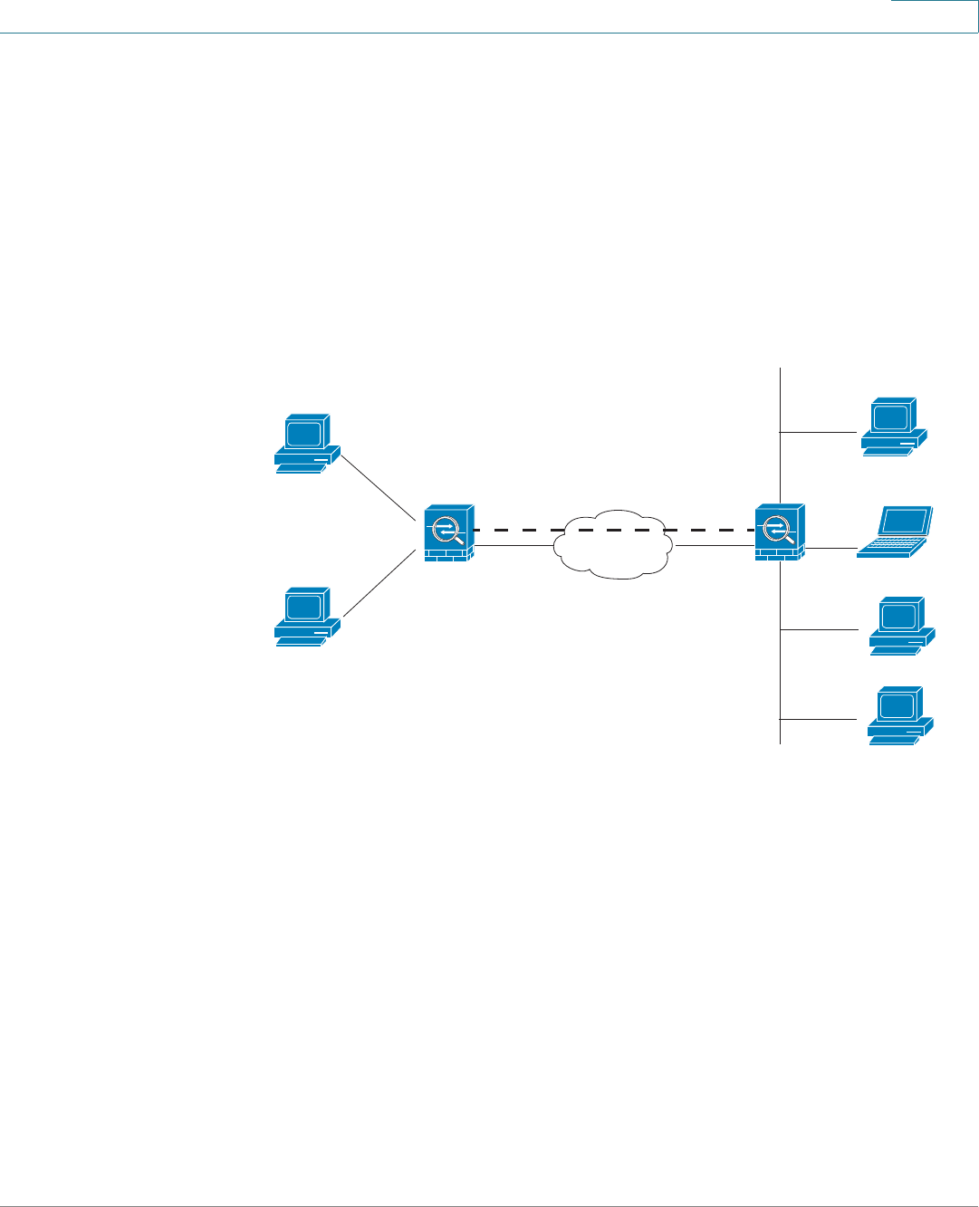
VPN
Configuring the Cisco IPSec VPN Client
Cisco ISA500 Series Integrated Security Appliance Administrator Guide 241
8
Figure 7 illustrates the client mode of operation. In this example, the security
appliance provides access to two PCs, which have IP addresses in the 10.0.0.0
private network space. These PCs connect to the Ethernet interface on the
security appliance, and the server assigns an IP address 192.168.101.2 to the
security appliance. The security appliance performs NAT or PAT translation over
the VPN tunnel so that the PCs can access the destination network. When
accessing the remote network 192.168.100.x, the hosts 10.0.0.3 and 10.0.04 will
be translated to 192.168.101.2, but hosts in the remote network 192.168.100.x can
not access the hosts 10.0.0.3 and 10.0.04.
Figure 8 Cisco IPSec VPN Client Connection
Network Extension Mode
Network Extension Mode (NEM) specifies that the PCs and other hosts at the client
end of the VPN tunnel should be given IP addresses that are fully routable and
reachable by the destination network over the tunneled network so that they form
one logical network. PAT is not used, which allows the client PCs and hosts to have
direct access to the PCs and hosts at the destination network. In NEM mode, the
Cisco VPN hardware client obtains a private IP address from a DHCP server over
the VPN tunnel.
Figure 9 illustrates the network extension mode of operation. In this example, the
security appliance acts as a Cisco VPN hardware client, connecting to a remote
Cisco IPSec VPN Server. The hosts attached to the security appliance have IP
addresses in the 10.0.0.0 private network space. The server does not assign an IP
address to the security appliance, and the security appliance does not perform
ISA500
as a Cisco IPSec VPN Client
(192.168.101.2)
10.0.0.3
10.0.0.4
Internet
Cisco Device
as a Cisco IPSec VPN Server
192.168.100.x
VPN tunnel
Inside
10.0.0.0
WAN
202.0.0.1
WAN
203.0.0.1
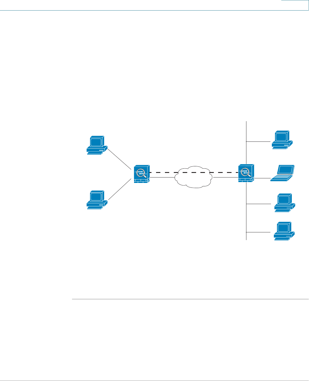
VPN
Configuring the Cisco IPSec VPN Client
Cisco ISA500 Series Integrated Security Appliance Administrator Guide 242
8
NAT or PAT translation over the VPN tunnel. When accessing the remote network
192.168.100.x, the hosts 10.0.0.3 and 10.0.04 will not be translated, and hosts in
the remote network 192.168.100.x can access the hosts 10.0.0.3 and 10.0.04
directly.
The client hosts are given IP addresses that are fully routable by the destination
network over the tunnel. These IP addresses could be either in the same subnet
space as the destination network or in separate subnets, assuming that the
destination routers are configured to properly route those IP addresses over the
tunnel.
Figure 9 Cisco IPSec VPN Network Extension Connection
General Settings
You can enable the Cisco IPSec VPN Client feature, configure the Auto Initiation
Retry settings, or manually connect or disconnect the IPSec VPN tunnels.
STEP 1 Click VPN -> Remote User Access -> Cisco IPSec VPN Client.
The Cisco IPSec VPN Client window opens.
STEP 2 Enter the following information:
•Cisco IPSec VPN Client Enable: Click On to enable the Cisco IPSec VPN
Client feature and set the security appliance as a Cisco VPN hardware client,
or click Off to disable it.
ISA500
as a Cisco IPSec VPN Client
10.0.0.3
10.0.0.4
Internet
Cisco Device
as a Cisco IPSec VPN Server
192.168.100.x
VPN tunnel
WAN
202.0.0.1
WAN
203.0.0.1

VPN
Configuring the Cisco IPSec VPN Client
Cisco ISA500 Series Integrated Security Appliance Administrator Guide 243
8
•Auto Initiation Retry: Click On to enable the Auto Initiation Retry feature, or
click Off to disable it. This feature is used to re-initiate the VPN connection to
the primary server if it does not response during the timeout. When the
primary server can not be connected over the timeout, the client will try to
initiate the VPN connection to the backup servers. If you enable this feature,
enter the following information:
-Retry Interval: Specify how often, in seconds, the security appliance
initiates the VPN conection to the primary server. The default is 120
seconds.
-Retry Limit: Enter the number of times the security appliance will retry a
connection initiation. The default is 0.
•Connect: To manually initiate the IPSec VPN connection, check the box of
the group policy you want and then click Connect.
•Disconnect: To manuall terminate an estalished the IPsec VPN connection,
click Disconnect.
STEP 3 Click Save to apply your settings.
Configuring the Group Policies for Cisco IPSec VPN Client
As a Cisco VPN hardware client, the security appliance will initiate the VPN
connection with a remote Cisco IPSec VPN Server. You can specify up to 16 group
policies used for Cisco IPSec VPN Client to establish the IPSec VPN tunnel.
STEP 1 Click VPN -> Remote User Access -> Cisco IPSec VPN Client.
The Cisco IPSec VPN Client window opens. All existing group policies are listed in
the table.
STEP 2 To add a group policy, click Add.
Other Options: To edit an entry, click Edit. To delete an entry, click Delete. To
delete multiple entries, check the boxes of multiple entries and click Delete
Selection.
After click Add or Edit, the Cisco IPSec VPN Client - Add/Edit window opens.
STEP 3 In the Basic Settings tab, enter the following inforamtion:
•Description: Enter the name for the group policy.

VPN
Configuring the Cisco IPSec VPN Client
Cisco ISA500 Series Integrated Security Appliance Administrator Guide 244
8
•Server (Remote Address): Enter the IP address of the remote Cisco IPSec
VPN server.
•Connection on Startup: Click On to establish the connection with the
remote server when your security appliance starts up, or click Off to disable
it. Only one connection can be active on startup.
•Authentication Method: The client must be properly authenticated before it
can access the remote network. Choose one of the following authentication
methods:
-Preshare: If you choose this option, specify the pre-shared key and the
group policy in the following fields.
Password: Enter the desired value, which the peer device must provide
to establish a connection. The pre-shared key must be entered exactly
the same here and on the remote server.
Group Name: Enter the name of the group policy that is defined on the
remote server. Your security appliance will use this group policy to
establish the VPN tunnel with the remote server. The server pushes the
security settings over the IPSec VPN tunnel to the clients.
-Certificate: If you choose this option, choose a local certificate and a
peer certificate for authentication. On the remote server, the selected
local certificate should be set as the peer certificate, and the selected
peer certificate should be set as the local certificate. If the certificates are
not in the list, go to the Device Management -> Certificate
Management page to import the certificates. See Managing the
Certificates for Authentication, page 310.
•Mode: Specify the operation mode before making a connection because the
client does not have a default mode. For more information about the
operation mode, see Modes of Operation, page 240.
•VLAN: If you choose the NEM mode, specify the VLAN that permits the
access from and to the private network of the remote server.
•User Name: Enter the user name used by the client to establish a VPN
connection.
•User Password: Enter the password used by the client to establish a VPN
connection.
STEP 4 In the Zone Access Control tab you can control the access from the zones in your
network to the remote network if you choose the Client mode. Click Permit to
VPN
Configuring the Cisco IPSec VPN Client
Cisco ISA500 Series Integrated Security Appliance Administrator Guide 245
8
permit the access, or click click Deny to deny the access. By default, the access
from all zones to the remote network is permitted.
NOTE The VPN access control rules that are automatically generated by the Zone
Access Control settings will be added to the firewall access rule table with
the priority higher than the default firewall access rules, but lower than the
custom firewall access rules.
STEP 5 In the Advanced Settings tab, enter the following information.
•Backup Server 1/2/3: You can specify up to three backup servers. When
the primary server is disconnected, your security appliance can initiate the
VPN connection to the backup servers. The backup server 1 has the highest
priority and the backup server 3 has the lowest priority.
NOTE The Cisco VPN hardware client can get the backup servers from the
remote Cisco IPSec VPN server during the tunnel negotiation. The
backup servers specified on the remote Cisco IPSec VPN server have
higher priority than the back servers specified on the Cisco VPN
hardware client. When the primary server is disconnected, firstly try
to connect to the backup servers specified on the Cisco IPSec VPN
server, and then try to connect to the backup servers specified on the
Cisco VPN hardware client.
•Peer Timeout: Enter the time in minutes that the client retries to connect the
backup server.
STEP 6 Click OK to save your settings.
STEP 7 Click Save to apply your settings.
STEP 8 To check the status and statistic information for IPSec VPN tunnels, go to the
Session Status -> VPN Table page. See Monitoring the IPSec VPN Status,
page 269.
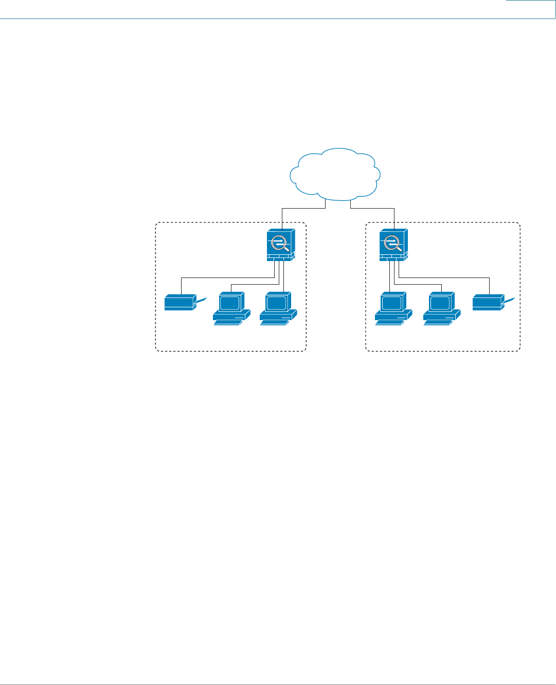
VPN
Configuring the Site-to-Site VPN
Cisco ISA500 Series Integrated Security Appliance Administrator Guide 246
8
Configuring the Site-to-Site VPN
The Site-to-Site VPN tunnel connects two routers to secure traffic between two
sites that are physically separated.
Figure 10 Site-to-Site VPN
This section describes how to configure a Site-to-Site VPN tunnel. It includes the
following topics:
•Configuration Tasks to Establish a Site-to-Site VPN, page 246
•General Site-to-Site VPN Settings, page 247
•Configuring the IPSec VPN Policies, page 248
•Configuring the IPSec IKE Policies, page 254
•Configuring the IPSec Transform Policies, page 256
Configuration Tasks to Establish a Site-to-Site VPN
To establish a Site-to-Site VPN tunnel, complete the following configuration tasks:
•Add the subnet IP address objects of the local network and remote
network. See Address Management, page 152.
235142
Site A
ISA500 ISA500
Site B
Inside
10.10.10.0
Outside
209.165.200.226
Outside
209.165.200.236
Inside
10.20.20.0
Personal
computers
Personal
computers
Printer Printer
Internet

VPN
Configuring the Site-to-Site VPN
Cisco ISA500 Series Integrated Security Appliance Administrator Guide 247
8
•(Optional) Import the certificate for authentication between two peers. Skip
this step if you want to use the pre-shared key for authentication. See
Managing the Certificates for Authentication, page 310.
•Enable the Site-to-Site VPN feature on your security appliance. See
General Site-to-Site VPN Settings, page 247.
•Configure the IPSec IKE policies. See Configuring the IPSec IKE Policies,
page 254.
•Configure the IPSec Transform policies. See Configuring the IPSec
Transform Policies, page 256.
•Configure the IPSec VPN policies. See Configuring the IPSec VPN
Policies, page 248.
•Check the box of an enabled IPSec VPN policy, and then click Connect to
initiate the IPSec VPN connection.
•Check the status and statistic information for IPSec VPN tunnels. See
Monitoring the IPSec VPN Status, page 269.
General Site-to-Site VPN Settings
STEP 1 Click VPN -> Site-to-Site -> IPSec Policies.
The IPSec Policies window opens. All existing IPSec VPN policies are listed in the
table. You can check the following information of an IPSec VPN policy:
•Name: The name of the IPSec VPN policy.
•Enable: Shows that the IPSec VPN policy is enabled or disabled.
•Status: Shows if the IPSec VPN tunnel is connected or disconnected.
•WAN Interface: The WAN interface that the traffic over the IPSec VPN tunnel
passes through.
•Peers: The IP address of the remote peer.
•Zone Access: The zone to which the remote peer can access.
•Local: The local network of the local peer.
•Remote: The remote network of the remote peer.
•Policy: The IKE policy used for the IPSec VPN policy.
VPN
Configuring the Site-to-Site VPN
Cisco ISA500 Series Integrated Security Appliance Administrator Guide 248
8
•Tranform: The tranform policy used for the IPSec VPN policy.
STEP 2 Click On to enable the Site-to-Site VPN feature, or click Off to disable it.
STEP 3 Check the box of an IPSec VPN policy in the Enable column to enable the IPSec
VPN policy, or uncheck the box to disable the policy.
STEP 4 After you enable the Site-to-Site VPN feature, check the box of an enabled IPSec
VPN policy and click Connect to establish the IPSec VPN tunnel.
STEP 5 To terminate a connected VPN tunnel between two peers, check the box and click
Disconnect.
STEP 6 To refresh the status of Site-to-Site VPN, click Refresh.
Configuring the IPSec VPN Policies
The Site-to-Site VPN policy is used to establish the IPSec VPN tunnel between
two peers. The ISA550 and ISA550W supports up to 50 IPSec VPN tunnels. The
ISA570 and ISA570W supports up to 100 IPSec VPN tunnels.
NOTE Before you create an IPSec VPN policy, make sure that the IKE and transform
policies are configured. Then you can apply the IKE and transform policy on the
IPSec VPN policy.
STEP 1 Click VPN -> Site-to-Site -> IPSec Policies.
The IPSec Policies window opens. All existing IPSec VPN policies are listed in the
table.
STEP 2 To add a new IPSec VPN policy, click Add.
Other options: To edit an entry, click Edit. To delete an entry, click Delete. To
delete multiple entries, check the boxes of the entries and then click Delete
Selection.
After you click Add or Edit, the IPSec Policies - Add/Edit window opens.
STEP 3 In the Basic Settings tab, enter the following information:
•Description: Enter the name for the IPSec VPN policy.

VPN
Configuring the Site-to-Site VPN
Cisco ISA500 Series Integrated Security Appliance Administrator Guide 249
8
•IPSec Policy Enable: Click On to enable the IPSec VPN policy, or click Off
to create only the IPSec VPN policy. For an enabled IPSec VPN policy, the
VPN tunnel can be connected by manually clicking Connect or be triggered
by traffic.
•Remote Type: Choose one of the following types for the remote peer:
-Static IP: Choose this option if the remote peer uses a static IP address.
Enter the IP address of the remote peer in the Address field.
-Dynamic IP: Choose this option if the remote peer uses a dynamic IP
address.
-FQDN (Fully Qualified Domain Name): Choose this option to use the
domain name of the remote network, such as vpn.company.com. Enter
the domain name of the remote peer in the Address field.
For the example as illustrated in Figure 10, the remote site, Site B, has a
public IP address of 209.165.200.236. You should choose Static IP for the
type, and enter 209.165.200.236 in the Address field.
•Authentication Method: Choose the authentication method for the IPSec
VPN policy.
-Preshare Key: If you choose this option, enter the desired value that the
peer device must provide to establish a connection. The same pre-
shared key has to be entered on the remote peer device.
-Certificate: If you choose this option, choose a local certificate and a
remote certificate for authentication. On the remote clients, the selected
local certificate should be set as the remote certificate, and the selected
remote certificate should be set as the local certificate. If the certificate
is not in the list, go to the Device Management -> Certificate
Management page to import the certificates. See Managing the
Certificates for Authentication, page 310.
•WAN Interface: Choose the WAN interface that the traffic passes through
over the IPSec VPN tunnel.
•Local Network: Choose the IP address of the local network. If you want to
configure the zone access control settings for Site-to-Site VPN, choose Any
for the local network.
•Remote Network: Choose the IP address of the remote network. You must
know the IP address of the remote network before connecting the IPSec
VPN tunnel.
VPN
Configuring the Site-to-Site VPN
Cisco ISA500 Series Integrated Security Appliance Administrator Guide 250
8
For the example as illustrated in Figure 10, Site A has a LAN IP address of
10.10.10.0 and Site B has a LAN IP address of 10.20.20.0. When you
configure the Site-to-Site VPN on Site A, the local network is 10.10.10.0 and
the remote network is 10.20.20.0.
If the IP address object is not in the list, choose Create an IP Address to add
a new address object. To maintain the address objects, go to the
Networking -> Address Object Management page. See Address
Management, page 152.
NOTE The security appliance can support multiple subnets for IPSec VPN
tunnel, you may need to select a group address object including
multiple VLANs for local and remote network.
STEP 4 In the Advanced Settings tab, enter the following information:
•PFS Enable: Click On to enable Perfect Forward Secrecy (PFS) to improve
security, or click Off to disable it. If you enable PFS, a Diffie-Hellman
exchange is performed for every phase-2 negotiation. PFS is desired on the
keying channel of the VPN connection.
•DPD Enable: Click On to enable Dead Peer Detection (DPD), or click Off to
disable it. DPD is a method of detecting a dead Internet Key Exchange (IKE)
peer. The method uses IPsec traffic patterns to minimize the number of
messages required to confirm the availability of a peer. DPD is used to
reclaim the lost resources in case a peer is found dead and it is also used to
perform IKE peer failover.
If you enable DPD, enter the following information:
-Delay Time: Enter the value of delay time in seconds between DPD
sending two keepalive messages for this IPSec VPN connection. The
default is 30 seconds.
-Detection Timeout: Enter the value of detection timeout in seconds. If no
response and no traffic over the timeout, declare the peer dead. The
default is 120 seconds.
-DPD Action: Choose one of the following actions over the timeout:
Hold: Traffic from local network to remote network can trigger the
security appliance to re-initiate the IPSec VPN tunnel over the timeout.
We recommend that you use Hold when the remote peer uses a static IP
address.
VPN
Configuring the Site-to-Site VPN
Cisco ISA500 Series Integrated Security Appliance Administrator Guide 251
8
Clean: Terminates the IPSec tunnel over the timeout. You must manually
re-initiate the IPSec VPN tunnel . We recommend that you use Clean
when the remote peer uses dynamic IP address.
Restart: Re-initiates the IPSec VPN tunnel for three times over the
timeout.
•Windows Network (NetBios) Broadcasting: Click On to allow access
remote network resources by using its NetBIOS name, for example,
browsing Windows Neighborhood. NetBIOS broadcasting can resolve a
NetBIOS name to a network address. This option allows NetBIOS
broadcasts to travel over the VPN tunnel.
•Access Control: You can control the incoming traffic from a remote VPN
network to the zones. Click Permit to permit the access, or click Deny to
deny the access. By default, the incoming traffic from the remote network to
all zones is permitted.
NOTE The VPN access rules that are automatically generated by the zone
access control settings will be added in the firewall access rule table
with the priority higher than the default firewall access rules, but
lower than the custom firewall access rules.
•Apply NAT Policies: Click On to apply the NAT settings for both the local
network and remote network communicating over the VPN tunnel. This
option is particularly useful in cases where both sides of a tunnel use either
the same or overlapping subnets.
-Translated Local Network: To translate the local network, select the
translated address object of the local network.
-Translated Remote Network: To translate the remote network, select
translated address object of the remote network.
If the IP address object is not in the list, choose Create an IP Address to add
a new address object. To maintain the IP address objects, go to the
Networking -> Address Object Management page. See Address
Management, page 152.
Figure 11 shows a networking example that simulates two merging
companies with the same IP addressing scheme. Two routers are connected
with a VPN tunnel, and the networks behind each router are the same. For
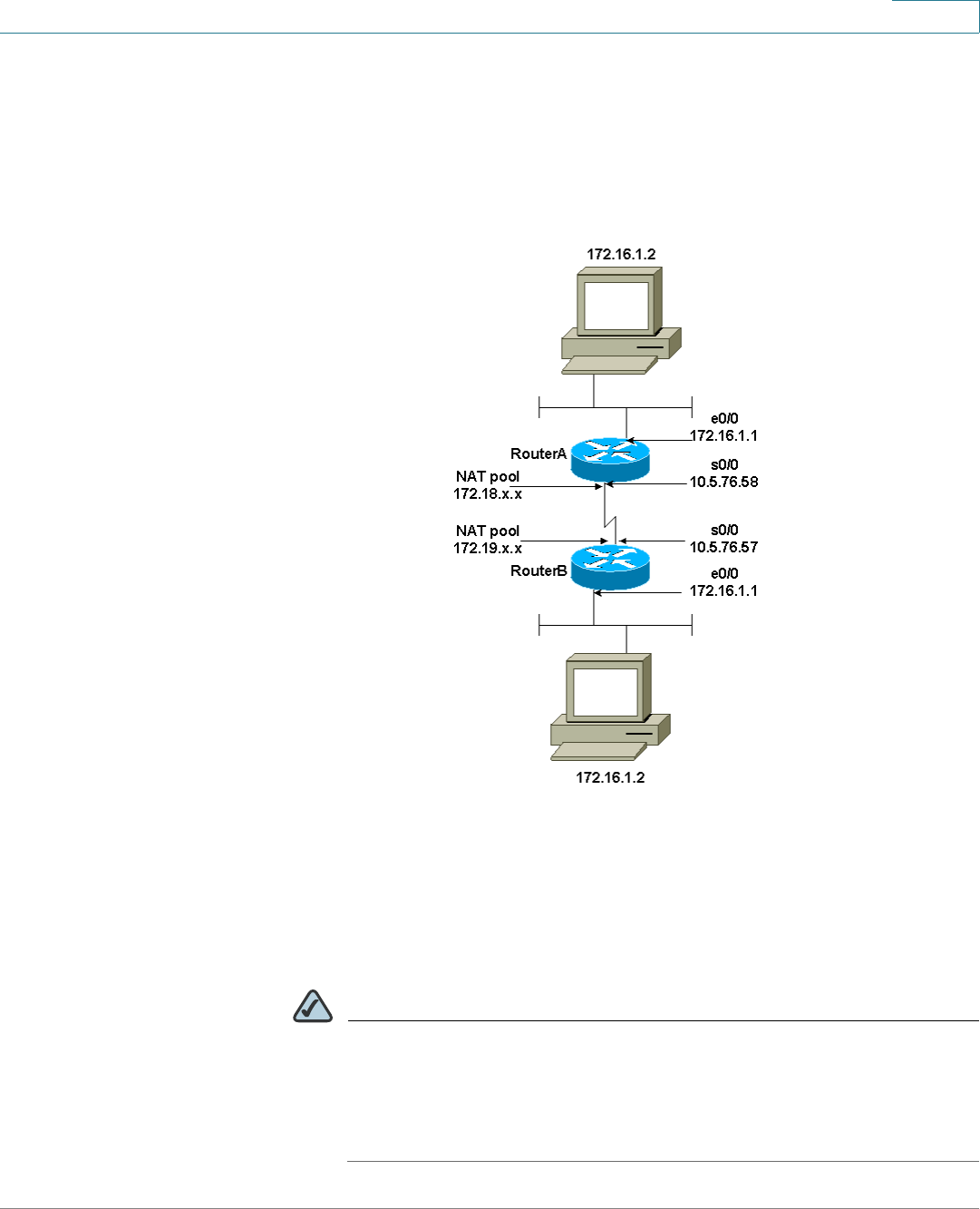
VPN
Configuring the Site-to-Site VPN
Cisco ISA500 Series Integrated Security Appliance Administrator Guide 252
8
one site to access the hosts at the other site, Network Address Translation
(NAT) is used on the routers to change both the source and destination
addresses to different subnets.
Figure 11 Networking example that simulates two merging companies with
the same IP addressing scheme
In this example, when the host 172.16.1.2 at Site A accesses the same IP-
addressed host at Site B, it connects to a 172.19.1.2 address rather than to
the actual 172.16.1.2 address. When the host at Site B to accesses Site A, it
connects to a 172.18.1.2 address. NAT on Router A translates any 172.16.x.x
address to look like the matching 172.18.x.x host entry. NAT on Router B
changes 172.16.x.x to look like 172.19.x.x.
NOTE This configuration only allows the two networks to communicate. It
does not allow for Internet connectivity. You need additional paths to
the Internet for connectivity to locations other than the two sites; in
other words, you need to add another router or firewall on each side,
with multiple routes configured on the hosts.
VPN
Configuring the Site-to-Site VPN
Cisco ISA500 Series Integrated Security Appliance Administrator Guide 253
8
•IKE Policy: Choose the IKE policy used for the IPSec VPN tunnel. If the IKE
policy is not in the list, go to the IKE Policies page to create new IKE policies.
See Configuring the IPSec IKE Policies, page 254.
•Transform: Choose the transform policy used for the IPSec VPN tunnel. If the
transform policy is not in the list, go to the Transform Policies page to create
new transform policies. See Configuring the IPSec Transform Policies,
page 256.
•Security Time: Enter the lifetime of the IPSec Security Association (SA). The
lifetime of the IPSec SA represents the interval after which the IPSec SA
becomes invalid. The IPSec SA is renegotiated after this interval. The default
is 1 hour.
STEP 5 In the VPN Failover tab, enter the following information:
•WAN Failover Enable: Click On to enable WAN Failover for the IPSec VPN
connection, or click Off to disable it. If you enable WAN Failover, the backup
WAN interface ensures that VPN traffic rolls over to the backup link
whenever the primary link fails. The security appliance will automatically
update the local WAN gateway for the VPN tunnel based on the
configurations of the backup WAN link. For this purpose, Dynamic DNS has
to be configured because the IP address will change due to failover, or let the
remote gateway use dynamic IP address.
NOTE To enable the WAN Failover for Site-to-Site VPN, make sure that the
secondary WAN interface was configured and the WAN redundancy
was set as the Failover or Load Balancing mode.
•Redundant Gateway: Click On to enable Redundant Gateway, or click Off to
disable it. If you enable Redundant Gateway, when the connection of remote
gateway is down, the backup connection automatically becomes active. A
backup policy comes into effect only if the primary policy fails.
-Select Backup Policy: Choose a policy to act as a backup of this policy.
-Failback Time to Switch: Enter the number of seconds that must pass to
confirm that the primary tunnel has recovered from a failure. If the primary
tunnel is up for the specified number of seconds, the security appliance
will switch to the primary tunnel by disabling the backup tunnel.
VPN
Configuring the Site-to-Site VPN
Cisco ISA500 Series Integrated Security Appliance Administrator Guide 254
8
NOTE The DPD should be enabled if you want to use the Redundant
Gateway feature for the IPSec VPN connection.
STEP 6 Click OK to save your settings.
STEP 7 Click Save to apply your settings.
NOTE Next Steps:
•To maintain the IKE policies, click Site-to-Site -> IKE Policies. See
Configuring the IPSec IKE Policies, page 254.
•To maintain the Tranform policies, click Site-to-Site -> Transform Policies.
See Configuring the IPSec Transform Policies, page 256.
Configuring the IPSec IKE Policies
The Internet Key Exchange (IKE) protocol is a negotiation protocol that includes an
encryption method to protect data and ensure privacy. It is also an authentication
method to verify the identity of devices that are trying to connect to your network.
You can create IKE policies to define the security parameters (such as
authentication of the peer, encryption algorithms, and so forth) to be used for a
VPN tunnel.
NOTE The security appliance supports up to 16 IKE policies.
STEP 1 Click VPN -> Site-to-Site -> IKE Policies.
The IKE Policies window opens. The default and custom IKE policies are listed in
the table.
STEP 2 To add a new IKE policy, click Add.
Other options: To edit an entry, click Edit. To delete an entry, click Delete. The
default IKE policy (DefaultIke) can not be edited or deleted.

VPN
Configuring the Site-to-Site VPN
Cisco ISA500 Series Integrated Security Appliance Administrator Guide 255
8
After you click Add or Edit, the IKE Policy - Add/Edit window opens.
STEP 3 Enter the following information:
•Name: Enter an unique name for the IKE policy.
•Encryption: Choose the algorithm used to negotiate the security
association. There are four algorithms supported by the security appliance:
ESP_3DES, ESP_AES-128, ESP_AES-192, and ESP_AES-256.
•HASH: Specify the authentication algorithm for the VPN header. There are
two HASH algorithms supported by the security appliance: SHA1 and MD5.
NOTE Ensure that the authentication algorithm is configured identically on
both sides.
•Authentication: Specify the authentication method that the security
appliance uses to establish the identity of each IPsec peer.
-PRE-SHARE: Uses a simple password based key to authenticate. The
alpha-numeric key is shared with IKE peer. Pre-shared keys do not scale
well with a growing network but are easier to set up in a small network.
-RSA-SIG: Uses a digital certificate to authenticate. RSA-SIG is a digital
certificate with keys generated by the RSA signatures algorithm. In this
case, a certificate must be configured in order for the RSA-Signature to
work.
•D-H Group: Choose the Diffie-Hellman group identifier, which the two IPsec
peers use to derive a shared secret without transmitting it to eachother. The
D-H Group sets the strength of the algorithm in bits. The lower the Diffie-
Hellman group number, the less CPU time it requires to execute. The higher
the Diffie-Hellman group number, the greater the security.
-Group 2 (1024-bit)
-Group 5 (1536-bit)
-Group 14 (2048-bit)
•Lifetime: Enter the number of seconds for the IKE Security Association to
remain valid. The default is 24 hours. As a general rule, a shorter lifetime
provides more secure ISAKMP negotiations (up to a point). However, with
shorter lifetimes, the security appliance sets up future IPsec SAs more
quickly.
VPN
Configuring the Site-to-Site VPN
Cisco ISA500 Series Integrated Security Appliance Administrator Guide 256
8
STEP 4 Click OK to save your settings.
STEP 5 Click Save to apply your settings.
Configuring the IPSec Transform Policies
A transform policy specifies the algorithms of integrity and encrytion the peers
will use to protect data communications. Two peers must use the same algorithm
to communicate.
NOTE The security appliance supports up to 16 transform policies.
STEP 1 Click VPN -> Site-to-Site -> Transform Policies.
The Transform Policies window opens. The default and custom transform policies
are listed in the table.
STEP 2 To add an IPSec transform policy, click Add.
Other options: To e d i t a n e n t r y, Edit. To delete an entry, click Delete. The default
transform policy (DefaultTrans) can not be edited or deleted.
After you click Add or Edit, the Transform Policy - Add/Edit window opens.
STEP 3 Enter the following information:
•Name: Enter an unique name for the transform policy.
•Integrity: Choose the hash algorithm used to ensure the data integrity. It
ensures that a packet comes from where it says it comes from, and that it has
not been modified in transit. The default is ESP_SHA1_HMAC.
-ESP_SHA1_HMAC: Authentication with SHA_1 (160-bit).
-ESP_MD5_HMAC: Authentication with MD5 (128-bit). MD5 has a smaller
digest and is considered to be slightly faster than SHA_1. A successful
(but extremely difficult) attack against MD5 has occurred; however, the
HMAC variant IKE uses prevents this attack.

VPN
Configuring the SSL VPN
Cisco ISA500 Series Integrated Security Appliance Administrator Guide 257
8
•Encryption: Choose the symmetric encryption algorithm that protects data
transmitted between two IPsec peers. The default is 168-bit Triple DES
(ESP_3DES). The Advanced Encryption Standard supports key lengths of
128, 192, 256 bits.
-ESP_3DES: Encryption with 3DES (168-bit).
-ESP_AES_128: Encryption with AES (128-bit).
-ESP_AES_192: Encryption with AES (192-bit).
-ESP_AES_256: Encryption with AES (256-bit).
STEP 4 Click OK to save your settings.
STEP 5 Click Save to apply your settings.
Configuring the SSL VPN
SSL VPN is a flexible and secure way to extend network resources to virtually any
remote user. The security appliance supports the SSL VPN, and interoperates with
the Cisco AnyConnect VPN Client software.
Figure 12 shows an example of SSL VPN. Users can remotely access the network
by using the Cisco AnyConnect VPN Client software. When the VPN tunnel is
established, each user will have an IP address on the internal network, such as
10.10.10.x.
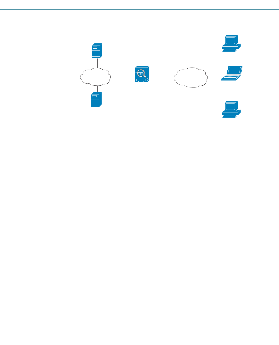
VPN
Configuring the SSL VPN
Cisco ISA500 Series Integrated Security Appliance Administrator Guide 258
8
Figure 12 SSL VPN for Remote Access
Use the SSL Remote Access pages to configure the SSL VPN gateway, SSL VPN
group policies, and SSL VPN portal. The security appliance supports multiple
concurrent SSL VPN sessions to allow remote users to access the LAN. It includes
the following sections:
•Elements of the SSL VPN, page 258
•Configuration Tasks to Establish a SSL VPN Tunnel, page 259
•Installing the Cisco AnyConnect VPN Client on User’s PC, page 260
•Importing the Certificates for User Authentication, page 260
•Configuring the SSL VPN Users, page 260
•Configuring the SSL VPN Gateway, page 261
•Configuring the SSL VPN Group Policies, page 263
•Configuring the SSL VPN Portal, page 266
Elements of the SSL VPN
Several elements work together to support SSL VPN.
•SSL VPN Users: Create your SSL VPN users. The user groups to which the
SSL VPN users belong must be assigned a specific SSL VPN group policy
to enable the SSL VPN service for the users. See Configuring the SSL VPN
Users, page 260.
Inside
10.10.10.0
Outside
ISA500
DNS Server
10.10.10.163
WINS Server
10.10.10.133
Internet
Internal
network
Cisco AnyConnect VPN Client
Cisco AnyConnect VPN Client
Cisco AnyConnect VPN Client

VPN
Configuring the SSL VPN
Cisco ISA500 Series Integrated Security Appliance Administrator Guide 259
8
•SSL VPN Group Policies: The default SSL VPN policy
(“SSLVPNDefaultPolicy”) is sufficient for most purposes. As needed, you
can custom new policies to meet specific business needs. See Configuring
the SSL VPN Group Policies, page 263.
•Cisco AnyConnect VPN Client: The Cisco AnyConnect VPN Client is the
next-generation VPN client, providing remote users with secure VPN
connections to the security appliance.
Configuration Tasks to Establish a SSL VPN Tunnel
You need to complete below configuration tasks to establish a SSL VPN tunnel.
•Download and install the Cisco AnyConnect VPN Client software on remote
user’s PC. See Installing the Cisco AnyConnect VPN Client on User’s PC,
page 260.
•Import the SSL VPN certificate to your security appliance used for user
authentication. See Importing the Certificates for User Authentication,
page 260.
•Enable and configure the SSL VPN gateway on your security appliance.
See Configuring the SSL VPN Gateway, page 261.
•Define the SSL VPN group policies. See Configuring the SSL VPN Group
Policies, page 263.
•Add SSL VPN users and user groups, and then specify the SSL VPN group
policy for each SSL VPN user group. See Configuring the SSL VPN Users,
page 260.
•Launch the Cisco AnyConnect VPN Client on the user’s PC, enter the
gateway IP Address:gateway interface to connect the remote gateway, and
then enter the user name and password to establish a SSL VPN tunnel.
•Check the status and statistic information of all SSL VPN sessions. See
Monitoring the SSL VPN Status, page 270.

VPN
Configuring the SSL VPN
Cisco ISA500 Series Integrated Security Appliance Administrator Guide 260
8
Installing the Cisco AnyConnect VPN Client on User’s PC
You can set up a user’s PC to run the Cisco AnyConnect VPN Client in standalone
mode by installing the client software for the appropriate operating system
directly on the user’s PC. In standalone mode, the user starts the Cisco
AnyConnect VPN Client, and needs to provide the authentication credentials.
The security appliance supports the Cisco AnyConnect VPN Client v2.x and v3.0
(SSL VPN function only). The Cisco AnyConnect VPN Client is compatible with the
following platforms:
•Windows 7 32-bit (x86) and 64-bit (x64)
•Windows Vista 32-bit (x86) and 64-bit (x64), including Service Packs 1 and
2 (SP1/SP2)
•Windows XP SP2+ 32-bit (x86) and 64-bit (x64)
•Mac OS X 10.5 and 10.6.x
•Linux Intel (2.6.x kernel)
You can find the software installer on the CD. If you have a CCO account, you can
access the SSL VPN portal to download the software installer from Cisco.com
website. For more information about the SSL VPN portal, see Configuring the SSL
VPN Portal, page 266.
Importing the Certificates for User Authentication
The SSL VPN gateway holds a CA certificate that is presented to the client when
the client first connects to the gateway. The purpose of this certificate is to
authenticate the server. For complete details about importing the certificates, see
Managing the Certificates for Authentication, page 310.
Configuring the SSL VPN Users
The ISA550 and ISA550W supports 25 SSL VPN users. The ISA570 and ISA570W
supports 50 SSL VPN users.
To configure the SSL VPN users and user groups, go to the Users -> Users &
Groups page. You can add all SSL VPN users to one group (such as “ SSL VPN
User Group”). However, if you have multiple SSL VPN group policies for different
SSL VPN users, you must create multiple user groups and specify different SSL

VPN
Configuring the SSL VPN
Cisco ISA500 Series Integrated Security Appliance Administrator Guide 261
8
VPN group policies for them. Specifying a SSL VPN group policy for a user group
can enable the SSL VPN service for all included SSL VPN users. For complete
details about the users and user groups, see Configuring the Users and Groups,
page 275
According to the user login settings specified on your security appliance, the SSL
VPN users can be authenticated by the local database or external AAA server
(such as Active Directory, LDAP, or RADIUS). For complete details about the user
login settings, see Configuring the Users and Groups, page 275 and
Configuring the User Authentication Settings, page 277.
Configuring the SSL VPN Gateway
Use the SSL VPN Configuration page to enable SSL VPN and configure the SSL
VPN gateway settings.
STEP 1 Click VPN -> SSL Remote Aceess -> SSL VPN Configuration.
The SSL VPN Configuration window opens.
STEP 2 Click On to enable SSL VPN, or click Off to disable SSL VPN. If you enable SSL
VPN, the security appliance is set as the SSL VPN server.
STEP 3 In the Gateway (Mandatory) area, enter the following information:
•Gateway Interface: Choose the WAN interface that the traffic passes
through over the SSL VPN tunnel.
•Gateway Port: Enter the port number used for the SSL VPN gateway. By
default, HTTPS or SSL typically operates on port 443. However, the SSL
VPN gateway should be flexible to operate on a user defined port. The SSL
VPN clients need to enter the entire address pair “Gateway IP Address: Port
Number” for connectting purposes.
•Certificate File: Choose a certificate to authenticate the users who want to
access your network resource through the SSL VPN tunnel. To import the
digital certificates for authentication, go to the Device Management ->
Certificate Management page. See Managing the Certificates, page 311.
•Client Address Pool: The SSL VPN gateway has a configurable address
pool with maximum size of 255 that is used to allocate IP addresses to the
remote clients. Enter the IP address pool for all remote clients. The client is
assigned an IP address by the SSL VPN gateway.

VPN
Configuring the SSL VPN
Cisco ISA500 Series Integrated Security Appliance Administrator Guide 262
8
NOTE Configure an IP address range that does not directly overlap with any
of addresses on your local network.
•Client Netmask: Enter the IP address of the netmask used for SSL VPN
clients. The Client Address Pool is used with the Client Netmask. If they are
set as follows, then the SSL VPN client will get a VPN address whose range
is from 10.0.0.1 to 10.0.0.254.
-Client Address Pool = 10.0.0.0
-Client Netmask = 255.255.255.0
•Client Domain: Enter the domain name used for the SSL VPN clients.
•Login Banner: When the users successfully log into the SSL VPN gateway,
a configurable login banner is displayed. Enter the message text to display
along with the banner.
STEP 4 In the Gateway (Optional) area, enter the following information:
•Idle Timeout: Enter the timeout value in seconds that the SSL VPN session
can remain idle.
•Session Timeout: Enter the timeout value in seconds that a SSL VPN
session can remain connected.
•Client DPD Timeout: Dead Peer Detection (DPD) allows detection of dead
peers. Enter the DPD timeout for client in this field.
•Gateway DPD Timeout: Enter the DPD timeout for SSL VPN gateway in this
field.
•Keep Alive: If you want the SSL VPN server to keep sending a message at
an interval, enter the value of interval in this field.
•Lease Duration: Enter the amount of time after which the SSL VPN client
must send an IP address lease renewal request to the server.
•Max MTU: Enter the maximum transmission unit for the session.
•Rekey Method: Specify the session rekey method (SSL or New Tunnel).
Rekey allows the SSL keys to be renegotiated after the session has been
established.
•Rekey Interval: Enter the frequency of the rekey in this field.
VPN
Configuring the SSL VPN
Cisco ISA500 Series Integrated Security Appliance Administrator Guide 263
8
•SSL VPN Portal Message: Enter the message that you want to display on
the SSL VPN portal. The SSL VPN portal provides a link to download the
Cisco AnyConnect VPN Client software installer from Cisco.com website.
The CCO account is required to log into the website for downloading. For
more information about the SSL VPN portal, see Configuring the SSL VPN
Portal, page 266.
STEP 5 Click Save to apply your settings.
Configuring the SSL VPN Group Policies
SSL VPN users of the group can establish the SSL VPN tunnels based on the
selected SSL VPN group policy to access your network resources. A SSL VPN
group policy applies to a specific network resource, IP address, or IP address
range on the LAN, or to other SSL VPN services that are supported by the security
appliance.
NOTE The security appliance supports up to 32 SSL VPN goup policies.
STEP 1 Click VPN -> SSL Remote Acess -> SSL VPN Group Policies.
The SSL VPN Group Policies window opens. The default and custom SSL VPN
group policies are listed in the table.
STEP 2 To add a new SSL VPN group policy, click Add.
Other options: To edit an entry, click Edit. To delete an entry, click Delete. To
delete multiple entries, check the boxes and then click Delete Selection. The
default SSL VPN group policy can not be deleted.
After you click Add or Edit, the Group Policy - Add/Edit window opens.
STEP 3 In the Basic Settings tab, enter the following information:
•Policy Name: Enter the name for the SSL VPN group policy.
•Primary DNS: Enter the IP address of the primary DNS server.
•Secondary DNS: Enter the IP address of the secondary DNS server.
•Primary WINS: Enter the IP address of the primary WINS server.

VPN
Configuring the SSL VPN
Cisco ISA500 Series Integrated Security Appliance Administrator Guide 264
8
•Secondary WINS: Enter the IP address of the secondary WINS server.
STEP 4 In the IE Proxy Settings tab, enter the following information:
The SSL VPN gateway can specify several Microsoft Internet Explorer (MSIE)
proxies for client PCs. If these settings are enabled, IE on the client PC is
automatically configured with these settings:
•IE Proxy Policy: Choose one of the following IE proxy policies:
-None: Allows the browser to use no proxy settings.
-Auto: Allows the browser to automatically detect the proxy settings.
-Bypass-Local: Allows the browser to bypass the proxy settings that are
configured on the remote user.
•Address: If you choose Bypass-Local, enter the IP address or domain name
of the MSIE proxy server. It is configured as an IPv4 address or fully qualified
domain name, followed by a colon and port number, for example
xxx.xxx.xxx.xxx:80.
•Port: Enter the port number of the MSIE proxy server.
•IE Proxy Exception: If you choose Bypass-Local, enter the IP address or
domain name of an exception host. This option allows the browser not to
send traffic for the given hostname or IP address through the proxy.
STEP 5 In the Split Tunneling Settings area, enter the following information:
Split tunneling permits specific traffic to be carried outside of the SSL VPN tunnel.
Traffic is either included (resolved in tunnel) or excluded (resolved through the
Internet Service Provider or WAN connection). Tunnel resolution configuration is
mutually exclusive. An IP address cannot be both included and excluded at the
same time.
•Enable Split Tunneling: By default, all of traffic from the SSL VPN clients is
directed through the SSL VPN tunnel. Check this box to enable split tunneling
so that the tunnel is used only for the traffic that is specified by the client
routes.
•Split Include: Choose one of the following options:
-Include Traffic: Allows you to add the client routes on the SSL VPN client
so that only traffic to the destination networks redirected through the SSL
VPN tunnels. To add a client route, enter the destination subnet to which

VPN
Configuring the SSL VPN
Cisco ISA500 Series Integrated Security Appliance Administrator Guide 265
8
a route is added on the SSL VPN client in the Address field and the the
subnet mask for the destination network in the Netmask field, and then
click Add.
-Exclude Traffic: Allows you to exclude the destination networks on the
SSL VPN client. The traffic to the destination networks is redirected using
the SSL VPN clients native network interface (resolved through the
Internet Service Provider or WAN connection). To add a destination
subnet, enter the destination subnet to which a route is excluded on the
SSL VPN client in the Address field and the the subnet mask for the
excluded destination in the Netmask field, and then click Add.
-Exclude LAN: If you choose Exclude Traffic, click True to deny the SSL
VPN clients to access the local LANs over the VPN tunnel, or click False
to allow the SSL VPN clients to access the local LANs over the VPN
tunnel.
•Split DNS: Split DNS provides the ability to direct DNS packets in clear text
over the Internet to domains served through an external DNS (serving your
ISP) or through SSL VPN tunnel to domains served by the corporate DNS.
For example, a query for a packet destined for corporate.com would go
through the tunnel to the DNS that serves the private network, while a query
for a packet destined for myfavoritesearch.com would be handled by the
ISP's DNS. By default, this feature is configured on the SSL VPN gateway and
is enabled on the client. To use Split DNS, you must also have Split Tunneling
configured.
To add a domain to the Cisco AnyConnect VPN Client for tunneling packets
to destinations in the private network, end the domian name in the field and
then click Add. To delete a domain, select it from the list and click Delete.
STEP 6 In the Zone-based Firewall Settings area, you can control the access from the
SSL VPN clients to the zones over the SSL VPN tunnels. Click Permit to permit the
access, or click Deny to deny the access. By default, the access for all zones is
permitted.
NOTE The VPN access rules that are automatically generated by the zone-based
firewall settings will be added to the firewall access rule table with the
priority higher than the default firewall ACL rules, but lower than the custom
firewall ACL rules.
STEP 7 Click OK to save your settings.

VPN
Configuring the L2TP Server
Cisco ISA500 Series Integrated Security Appliance Administrator Guide 266
8
STEP 8 Click Save to apply your settings.
Configuring the SSL VPN Portal
User can access the SSL VPN portal via web browser from WAN or LAN side to
download the Cisco AnyConnect VPN Client software installer from Cisco.com
website. The CCO account is required to log into the website for downloading the
software installer.
For example, if the IP address of the SSL VPN gateway is 173.39.202.103, enter
https://173.39.202.103/sslvpn in the address bar to open the SSL VPN portal from
WAN side. Or if the IP address of the default LAN is 192.168.1.1, enter the https://
192.168.1.1/sslvpn in the address bar to open the SSL VPN portal from LAN side.
STEP 1 Click VPN -> SSL Remote Acess -> SSL VPN Portal.
The SSL VPN Portal window opens.
STEP 2 Enter the message that you want to display on the SSL VPN portal.
STEP 3 The SSL VPN portal provides a link to download the Cisco AnyConnect VPN Client
software installer from Cisco.com website. Click Download to open the website
and enter your CCO account to login. Depending on your operating system or
platform, choose the correct installer package.
Configuring the L2TP Server
Layer 2 Tunneling Protocol (L2TP) is a VPN tunneling protocol that allows remote
clients to use the public IP network to securely communicate with private
corporate network servers.
L2TP protocol is based on the client and server model. The security appliance can
terminate the L2TP-over-IPsec connections from incoming Microsoft Windows
2000 and Windows XP clients.
STEP 1 Click VPN -> L2TP Server.
The L2TP Server window opens.
VPN
Configuring the L2TP Server
Cisco ISA500 Series Integrated Security Appliance Administrator Guide 267
8
STEP 2 Click On to enable L2TP server, or click Off to disable it.
STEP 3 If you enable L2TP, enter the following information:
•Listen WAN Interface: Choose the WAN interface on which the L2TP server
listens to accept the incoming L2TP VPN connection.
•User Name: Enter the user name that all L2TP clients use to access the L2TP
server.
•Password: Enter the password that all L2TP clients use to access the L2TP
server.
NOTE All L2TP clients use the same user name and password to log into the
L2TP server.
•MTU: Enter the MTU size in bytes that can be sent over the network (the
range from 128 to 1400 bytes). The default is 1400 bytes.
•Authentication Method: You can choose either CHAP or PAP, or both to
authenticate to the L2TP clients. Click On to enable CHAP or PAP, or click Off
to disable it.
•Local Service IP: Enter the IP address of the established PPP link.
•Address Pool: The L2TP server assigns IP addresses to L2TP clients. Enter
the starting IP address in the Start IP field and the ending IP address in the
End IP field.
•DNS1 IP: Enter the IP address of the primary DNS server.
•DNS2 IP: Optionally, enter the IP address of the secondary DNS server.
•Enable over IPSec: Click On to enable the data encryption over the IPSec
VPN tunnel, or click Off to disable it.
•Preshare Key: The data encryption over the IPSec VPN tunnel uses a pre-
shared key for authentication. If you enable Enable over IPSec, enter the
desired value, which the L2TP clients must provide to establish a connection.
The pre-shared key must be entered exactly the same here and on the L2TP
clients.
STEP 4 Click Save to apply your settings.

VPN
Configuring the VPN Passthrough
Cisco ISA500 Series Integrated Security Appliance Administrator Guide 268
8
Configuring the VPN Passthrough
You need to configure VPN passthrough if there are devices behind the security
appliance that need to set up the VPN tunnels independently, for example, to
connect to another router on the WAN.
STEP 1 Click VPN -> Passthrough.
The Passthrough window opens.
STEP 2 Enter the following information:
•L2TP: Click On to allow L2TP clients at LAN site to connect to a L2TP server
on Internet, or click Off to disable it.
•PPTP: Click On to allow the hosts at LAN site to establish a tunnel with a
PPTP server on Internet, click Off to disable it.
•IPSec: Click On to allow the IPSec traffic to pass through the security
appliance over the IPSec VPN tunnel, or click Off to disable it. The VPN
tunnel can be established by a Site-to-Site VPN session or a Cisco IPSec
VPN session.
STEP 3 Click Save to apply your settings.
Viewing the VPN Status
Use the Session Status pages to view the status and statistic information for IPSec
VPN and SSL VPN sessions, and manually connect or disconnect the VPN tunnels.
It includes the following sections:
•Monitoring the IPSec VPN Status, page 269
•Monitoring the SSL VPN Status, page 270
VPN
Viewing the VPN Status
Cisco ISA500 Series Integrated Security Appliance Administrator Guide 269
8
Monitoring the IPSec VPN Status
The VPN Table page displays the status and statistic information for all IPSec VPN
sessions.
STEP 1 Click VPN -> Session Status -> VPN Table.
The VPN Table window opens.
STEP 2 In the Active Sessions tab, all IPSec VPN sessions are listed in the table.
•Name: The name of the VPN policy that is used for the IPSec VPN session.
•VPN Type: The connection type of the IPSec VPN session, such as Site-to-
Site, Cisco IPSec VPN server, or Cisco IPSec VPN client.
•WAN Interface: The WAN interface that is used for the IPSec VPN session.
•Remote Gateway: The IP address of the remote gateway for a Site-to-Site
VPN session or the IP address of the remote client for a Cisco IPSec VPN
session.
•Local Network: The subnet IP address and netmask of your local network.
•Remote Network: The subnet IP address and netmask of the remote
network.
•Connect: To manually establish a VPN connection, click Connect.
•Disconnect: To terminate an active VPN connection, click Disconnect.
NOTE When a VPN policy is in place and enabled, a connection is triggered
by any traffic that matches up with the policy and the VPN tunnel is set
up automatically. However, you can use the Connect or Disconnect
button to manually connect or disconnect the VPN tunnel.
STEP 3 In the IPSec VPN Statistic tab, you can view the statistic information for all active
IPSec VPN sessions:
•Name: The name of the VPN policy that is used for the IPSec VPN session.
•VPN Type: The connection type of the IPSec VPN session, such as Site-to-
Site, Cisco IPSec VPN server, or Cisco IPSec VPN client.
•WAN Interface: The WAN interface that is used for the IPSec VPN session.

VPN
Viewing the VPN Status
Cisco ISA500 Series Integrated Security Appliance Administrator Guide 270
8
•Remote Gateway: The IP address of the remote gateway for a Site-to-Site
VPN session or the IP address of the remote client for a Cisco IPSec VPN
session.
•Tx Bytes: The total volume of traffic in Kilobytes transmitted from the VPN
tunnel.
•Rx Bytes: The total volume of traffic in Kilobytes received from the VPN
tunnel.
•Tx Pkts: The number of IP packets transmitted from the VPN tunnel.
•Rx Pkts: The number of IP packets received from the VPN tunnel.
Monitoring the SSL VPN Status
The SSL VPN Monitoring page displays the status and traffic statistic information
of all active SSL VPN sessions.
STEP 1 Click VPN -> Session Status -> SSL VPN Monitoring.
The SSL VPN Monitoring window opens.
STEP 2 In the Active Sessions tab, all active SSL VPN sessions are listed in the table.
•Session ID: The SSL VPN session ID.
•User Name: The name of the logged SSL VPN user.
•Client IP (Actual): The actual IP address used by the SSL VPN client.
•Client IP (VPN): The virtual IP address of the SSL VPN client assigned by the
SSL VPN gateway.
•Time Connected: The amount of time since the user first established the
connection.
•Disconnect: Click Disconnect to terminate an active SSL VPN session and
hence the associated SSL VPN tunnel.
•Disconnect All: Click Disconnect All to terminate all active SSL VPN
sessions and hence all associated SSL VPN tunnels.
STEP 3 In the SSL VPN Statistics tab, you can see the statistic information for all active
SSL VPN sessions or for a single SSL VPN session.

VPN
Viewing the VPN Status
Cisco ISA500 Series Integrated Security Appliance Administrator Guide 271
8
CSTP is a Cisco proprietary protocol for SSL VPN tunneling. “In” means “from the
client” and “Out” means “to the client”. The client is the PC running the Cisco
AnyConnect VPN Client software that connects to the security appliance running
the SSL VPN server.
A CSTP frame is a packet carrying CSTP protocol information. There are two
major frame types, control frames and data frames. Control frames implement
control functions within the protocol. Data frames carry the client data, such as the
tunneled payload.
The following table displays the global statistic information. To clear the global
statistic information, click Clear Global.
The Statistic table lists the statistic information for each SSL VPN session. The
following information is displayed for a single SSL VPN session. To clear the
statistic information of the SSL VPN session, click Clear.
Active Users The number of all connected SSL VPN users.
In CSTP frames The number of CSTP frames received from all clients.
In CSTP bytes The total number of bytes in the CSTP frames received
from all clients.
In CSTP data The number of CSTP data frames received from all clients.
In CSTP control The number of CSTP control frames received from all
clients.
Out CSTP
frames
The number of CSTP frames sent to all clients.
Out CSTP bytes The total number of bytes in the CSTP frames sent to all
clients.
Out CSTP data The number of CSTP data frames sent to all clients.
Out CSTP
control
The number of CSTP control frames sent to all clients.
Session ID The SSL VPN session ID.
In CSTP frames The number of CSTP frames received from the client.

VPN
Viewing the VPN Status
Cisco ISA500 Series Integrated Security Appliance Administrator Guide 272
8
In CSTP bytes The total number of bytes in the CSTP frames received
from the client.
In CSTP data The number of CSTP data frames received from the client.
In CSTP control The number of CSTP control frames received from the
client.
Out CSTP
frames
The number of CSTP frames sent to the client.
Out CSTP bytes The total number of bytes in the CSTP frames sent to the
client.
Out CSTP data The number of CSTP data frames sent to the client.
Out CSTP
control
The number of CSTP control frames sent to the client.

9
Cisco ISA500 Series Integrated Security Appliance Administrator Guide 273
User Management
This chapter describes how to manage the users and user groups, and configure
the user login settings when they try to access your network resources.
•About the Users and Groups, page 273
•Configuring the Users and Groups, page 275
•Configuring the User Authentication Settings, page 277
•Viewing Active User Sessions, page 287
To access the Users pages, click Users in the left hand navigation pane.
About the Users and Groups
The security appliance maintains the user and user group information in the local
database. The local database supports up to 100 users and 16 user groups. A
user group can include up to 100 users. Any user must be a member of a user
group. It includes the following sections:
•Available Services for User Groups, page 273
•Default User and Group, page 274
•Preempt the Administrators, page 274
Available Services for User Groups
A user can only belong to one user group. The users in the same group shares the
same service policy. A user group has only one service policy. The services
available for a user group include:
•Web Login: Allows the members of the group to log into the Configuration
Utility through the web brower to view the configurations only or to set all
configurations.
User Management
About the Users and Groups
Cisco ISA500 Series Integrated Security Appliance Administrator Guide 274
9
NOTE You cannot disable the web login service or change its web login
service level for the default user group (admin).
•SSL VPN: Allows the members of the group at the remote site to establish
the SSL VPN tunnels based on the selected SSL VPN group policy to
access your network resources. The Cisco AnyConnect VPN Client must be
installed on the user’s PC.
•Cisco IPSec VPN: Allows the members of the group at the remote site to
securely access your network resources over the IPSec VPN tunnels.
•Captive Portal: Allows the wireless users who authenticated successfully
to be directed to a specified web page (portal) before they can access the
Internet. This service only applies to the ISA550W and ISA570W.
NOTE The security appliance can perform the authentications in parallel when
multiple services need to authenticate at the same time.
Default User and Group
The default administrator account (user name: cisco, password: cisco) is an
administrative account that has fully privilege to set the configurations and read
the system status. It does not belong to any user group. To prevent unauthorized
access, you are forced to immediately change the default user name and
password at its first login. See Changing the User Name and Password of the
Default Administrator Account at Your First Login, page 27. The default
administrator account cannot be deleted.
The default user group (admin) is a user group that has the administrative web
login access ability and enables the SSL VPN, Cisco IPSec VPN, and captive
portal (for ISA550W and ISA570W only) services. You cannot delete the default
user group, but can modify its service policy settings.
Preempt the Administrators
If an administrator account was already logged in, when the administrator account
attempts to log in again, a prompted warning message is displayed. Click Yes to
kick off the previous login, or click No to retun to the login screen.

User Management
Configuring the Users and Groups
Cisco ISA500 Series Integrated Security Appliance Administrator Guide 275
9
Configuring the Users and Groups
This section describes how to maintain the users and user groups in local
database. It includes the following topics:
•Configuring Local Users, page 275
•Configuring Local User Groups, page 276
Configuring Local Users
The local database supports up to 100 users. You can add new accounts for
specific services, such as the SSL VPN and Cisco IPSec VPN services.
STEP 1 Click Users -> Users & Groups.
The Users & Groups window opens. All existing local users are listed in the Local
Users table.
STEP 2 In the Local Users area, click Add to add a user.
Other options: To edit an entry, click Edit. To delete an entry, click Delete. To
delete multiple entries, check the boxes of multiple entries and click Delete
Selection.
After you click Add/Edit, the Local User - Add/Edit window opens.
STEP 3 Enter the following information:
•User: Enter an unique identifier that contains the letters, numbers, or
underline for the user.
•New Password: Enter the password for the user. Passwords are case-
sensitive.
NOTE Restrictions for password: The password should contain at least
three types of these character classes: lower case letters, upper case
letters, numbers, and special characters. Do not repeat any character
more than three times consecutively. Do not set the password as the
user name or the reversed user name. The password cannot be set as
“cisco”, “ocsic”, or any variant obtained by changing the capitalization
of letters.
User Management
Configuring the Users and Groups
Cisco ISA500 Series Integrated Security Appliance Administrator Guide 276
9
•New Password Confirm: Enter the password again for confirmation.
•Group: Choose the user group to which the user belongs.
NOTE For SSL VPN or Cisco IPSec VPN users, you need to enable the
corresponding services for the user groups to which they belongs.
STEP 4 Click OK to save your settings.
Configuring Local User Groups
Groups are used to create a logical grouping of users that share the service
policies. The local database supports up to 16 groups.
STEP 1 Click Users -> Users & Groups.
The Users & Groups window opens. All existing user groups are listed in the
Groups table.
STEP 2 In the Groups area, click Add to add a user group.
Other options: To edit an entry, click Edit. To delete an entry, click Delete. To
delete multiple entries, check the boxes of multiple entries and click Delete
Selection.
After you click Add or Edit, the Group - Add/Edit window opens.
STEP 3 In the Group Settings tab, enter the following information:
•Name: Enter an unique name that contains the letters, numbers, or underline
for the user group.
•Services: Specify the service policy for the user group. You can enable
multiple services for the user group.
-Web Login: Specify the web login policy for the group.
Disable: All members of the group cannot log into the Configuration
Utility through the web browser.
Read Only: All members of the group can only read the system status
after they login. They can not edit any configuration.

User Management
Configuring the User Authentication Settings
Cisco ISA500 Series Integrated Security Appliance Administrator Guide 277
9
Administrator: All members of the group have full privilege to set the
configurations and read the system status.
-SSLVPN: Choose a SSL VPN group policy so that all members of the
group at the remote site can establish the SSL VPN tunnels based on the
selected SSL VPN group policy to access your network resources, or
choose Disable to disable it. For more information about the SSL VPN
group policy, see Configuring the SSL VPN Group Policies, page 263.
-Cisco IPSec VPN: Click Enable to enable the Cisco IPSec VPN service
so that all members of the group can access the your network resources
over the IPSec VPN tunnels, or click Disable to disable it.
-Captive Portal: Click Enable to enable the Captive Portal service, or click
Disable to disable it. If you enable Captive Portal, the wireless members
of the user group who authenticated successfully will be directed to a
specified web page (portal) before they can access the Internet. This
service only applies to the ISA550W and ISA570W.
STEP 4 In the Membership tab, specify the members of the group.
•To add a member, select the member from the User list and click the right
arrow ->. The members of the groups appear in the Membership list.
•To delete a member from the user group, select the member from the
Membership list and click the left arrow <-.
STEP 5 Click OK to save your settings.
Configuring the User Authentication Settings
The security appliance provides a mechanism for user level authentication. It
authenticates all users when they attempt to access your network resources in
different zones. Users on the VLANs performs only local tasks, and are not
required to be authenticated by the security appliance.
User level authentication can be performed by using the local database that is
stored on the security appliance, an AAA server ( a variety of AAA server types
are supported, such as RADIUS, Lightweight Directory Access Protocol (LDAP),
Active Directory (AD)), or both.

User Management
Configuring the User Authentication Settings
Cisco ISA500 Series Integrated Security Appliance Administrator Guide 278
9
The local database on the security appliance can support up to 100 users and 16
groups. If you have more than 100 users, you need to use the AAA server for
authentication.
This section includes the following topics:
•Authentication Methods for User Login, page 278
•Using Local Database for Authentication, page 279
•Using RADIUS Server for Authentication, page 279
•Using Local Database and RADIUS Server for Authentication, page 282
•Using LDAP for Authentication, page 283
•Using Local Database and LDAP for Authentication, page 286
•Configuring the User Session Settings, page 286
Authentication Methods for User Login
The security appliance supports the following authentication methods for user
login.
•Local Database: Allows you to use the local database for authentication if
the number of users is relatively small. Only the local users in local database
are allowed to access the network resources. See Using Local Database
for Authentication, page 279.
•RADIUS: Allows you to use the RADIUS server for authentication if you
have more than 100 users. See Using RADIUS Server for Authentication,
page 279.
•RADIUS + Local Database: Allows you to use both the RADIUS server and
local database for authentication. See Using Local Database and RADIUS
Server for Authentication, page 282.
•LDAP: Allows you to use the LDAP for authentication if you use an AAA
server such as LDAP and AD to maintain the user and user group
information. See Using LDAP for Authentication, page 283.
•LDAP + Local Database: Allows you to use both the LDAP and local
database for authentication. See Using Local Database and LDAP for
Authentication, page 286.

User Management
Configuring the User Authentication Settings
Cisco ISA500 Series Integrated Security Appliance Administrator Guide 279
9
Using Local Database for Authentication
Use the local database to authenticate the users when the number of users
accessing the network is less than 100 users. When you use the local database for
authentication, the local database verifies the user name and password
information of the users who try to access the network. Only the valid local users
are allowed to access the network.
STEP 1 Click Users -> Settings.
The User Settings window opens.
STEP 2 In the User Login Settings area, choose Local Database as the authentication
method from the Authentication Method drop-down list.
STEP 3 Click Save to apply your settings.
Using RADIUS Server for Authentication
Use the RADIUS server to authenticate the users when more than 100 users need
to access the network. The security appliance uses the Framed-Filter-ID attribute
to store the user and group information in the RADIUS server, and checks a user’s
credentials by using the Password Authentication Protocol (PAP) authentication
scheme.
If you use RADIUS for user authentication, users must log into the security
appliance using HTTPS in order to encrypt the password. The security appliance
verifies the user name and password information of the users through the RADIUS
server. The RADIUS server returns the authentication result to the security
appliance. For a valid RADIUS user, the security appliance checks its user group
service policy from the local database and permits the access. For a invalid
RADIUS user, the security appliance denies the access.
NOTE The user group service policies can only be configured locally. All user groups on
an AAA server need to be duplicated locally.
STEP 1 Click Users -> Settings.
The User Settings window opens.

User Management
Configuring the User Authentication Settings
Cisco ISA500 Series Integrated Security Appliance Administrator Guide 280
9
STEP 2 In the User Login Settings area, choose RADIUS as the authentication method
from the Authentication Method drop-down list.
STEP 3 Click Configure to configure the RADIUS settings.
The RADIUS Settings window opens.
STEP 4 In the Settings tab, choose the RADIUS group for authentication and configure the
global timeout and retry settings.
•Global RADIUS Settings: Specify the global timeout and retry settings for
the selected RADIUS servers:
-RADIUS Server Timeout: Enter the number of seconds that the
connection can exist before re-authentication is required. The default
value is 10 seconds.
-Retries: Enter the number of retries for the device to re-authenticate with
the RADIUS server. If the RADIUS server does not respond within the
specified number of retries, the connection is dropped. The default value
is 3.
•RADIUS Servers: Choose the RADIUS group index from the drop-down list.
The RADIUS server settings of the selected group are disaplayed. You can
edit these settings here but the settings you specify will replace the default
settings of the selected group. To maintain the RADIUS settings, go to the
Device Management -> RADIUS Settings page. See Configuring the
RADIUS Servers, page 319.
STEP 5 In the RADIUS Users tab, enter the following informaiton:
•Allow Only Users Listed Locally: Click On to permit only the RADIUS users
also be present in the local database for login, or click Off to disable it.
•Mechanism for Setting User Group Membership for RADIUS Users:
Select one of the following mechanisms to configure the user group
memberships for RADIUS users:
-Use RADIUS Filter-ID: Find the group information by using the Framed-
Filter-ID attribute from the RADIUS server.
For example, the RADIUS server has three user groups (Group1, Group2,
and Group3) and the local database has two user groups (Group1, and
Group2). The following table displays the user group membership
settings.

User Management
Configuring the User Authentication Settings
Cisco ISA500 Series Integrated Security Appliance Administrator Guide 281
9
In the above table, if the User1 in the RADIUS server belongs to the
Group1 and the User1 in the local database belongs to the Group2, then
the User1 belongs to the Group1 after passed the RADIUS authentication.
If the User1 in the RADIUS server belongs to the Group3, but the local
database has not the Group3, then the User1 is set to the specified
default group.
-Local Configuration Only: Find the user group membership information
from the local database only.
For example, the RADIUS server has three user groups (Group1, Group2,
and Group3) and the local database has two user groups (Group1, and
Group2). The following table displays the user group membership
settings.
In the above table, if the User1 in the RADIUS server belongs to the
Group1 and the User1 in the local database belongs to the Group2, then
the User1 belongs to the Group2 after passed the RADIUS
authentication. If the User1 doex not exist in the local database, it is set to
the specified default group.
Local
Database
Settings
RADIUS Server Settings
User1 in Group1 User1 in Group2 User1 in Group3
User1 in Group1 Group1 Group2 Default Group
User1 in Group2 Group1 Group2 Default Group
User1 does not
exist
Group1 Group2 Default Group
Local
Database
Settings
RADIUS Server Settings
User1 in Group1 User1 in Group2 User1 in Group3
User1 in Group1 Group1 Group1 Group1
User1 in Group2 Group2 Group2 Group2
User1 does not
exist
Default Group Default Group Default Group

User Management
Configuring the User Authentication Settings
Cisco ISA500 Series Integrated Security Appliance Administrator Guide 282
9
•Defualt User Group to Which all RADIUS Users Belong: If the group of a
RADIUS user does not exist in the local database, you can set the RADIUS
user to a specific local user group. Choose a local user group as the default
local group to which the RADIUS user belongs.
STEP 6 In the Test tab, enter the user and password credentials in the User and
Password fields to test the configured RADIUS settings. Click the Test button to
verify whether the RADIUS user is valid
STEP 7 Click OK to save your settings.
STEP 8 Click Save to apply your settings.
Using Local Database and RADIUS Server for Authentication
You can use both the local database and RADIUS server to authenticate the users
who try to access the network.
When you use both the local database and RADIUS server for authentication, the
security appliance first verifies the user name and password information of the
users through the RADIUS server. The RADIUS server returns the authentication
result to the security appliance. For a valid RADIUS user, the security appliance
checks its user group service policy from the local database and allows the user
to access the network. For an invalid RADIUS user, then the security appliance
uses the local database to verify the user. For a valid local user, the security
appliance checks its user group service policy from the local database and allows
the user to access the network. For an invalid local user, the security appliance
denies the user to access the network.
STEP 1 Click Users -> Settings.
The User Settings window opens.
STEP 2 In the User Login Settings area, choose RADIUS + Local Database as the
authentication method from the Authentication Method drop-down list .
STEP 3 Click Configure to configure the RADIUS settings for user authentication.
The RADIUS Settings window opens. To configure the RADIUS server settings for
user authentication, see Using RADIUS Server for Authentication, page 279.
STEP 4 Click Save to apply your settings.

User Management
Configuring the User Authentication Settings
Cisco ISA500 Series Integrated Security Appliance Administrator Guide 283
9
Using LDAP for Authentication
The security appliance can use the LDAP directory for user authentication, with
support for three schemes including Microsoft Active Directory, RFC2798
InterOrgPerson, and RFC2307 Network Information Service.
STEP 1 Click Users -> Settings.
The User Settings window opens.
STEP 2 In the User Login Settings area, choose LDAP as the authentication method from
the Authentication Method drop-down list.
STEP 3 Click Configure to configure the LDAP settings.
The LADP Settings window opens.
STEP 4 In the Settings tab, enter the following information:
•IP Address: Enter the IP address of the LDAP server that you use for
authentication.
•Port Number: Enter the number of the listening port used on the LDAP
server. Enter a value from 1 to 65535. The default is 389.
•Server Timeout: Enter the amount of time in seconds that the security
appliance will wait for a response from the LDAP server before timing out.
•Login Method: Choose one of the following login methods:
-Annonymous Login: Choose this option if the LDAP server allows for the
user tree to be accessed anonymously.
-Give Login Name or Location in Tree: Choose this option to build the
distinguished name of the user that is used to bind to the LDAP server
from the Primary Domain and User Tree for Login to Server fields in the
Directory tab.
-Give Bind Distinguished Name: Choose this option if the destination
name is known. You must provide the destination name explicitly to be
used to bind to the LDAP server.
•Login User Name: If you choose Give Login Name or Location in Tree or
Give Bind Distinguished Name as the login method, enter the user name of
the account that can log into the LDAP directory.

User Management
Configuring the User Authentication Settings
Cisco ISA500 Series Integrated Security Appliance Administrator Guide 284
9
•Login Password: If you choose Give Login Name or Location in Tree or
Give Bind Distinguished Name as the login method, enter the password of
the account that can log into the LDAP server.
•Protocol Version: Choose either LDAP Version 2 or LDAP Version 3. Most
LDAP directories, including Active Directory, use LDAP Version 3.
STEP 5 In the Schema tab, enter the following information:
•LDAP Schema: Choose one of the following schemes:
-Microsoft Active Directory
-RFC2798 InetOrgPerson
-RFC2307 Network Information Service
•User Objects: The selected predefined scheme will automatically populate
below fields with their correct values. The fields that are grayed out cannot
be edited, but you can manually specify some editable fields if you have
specific or proprietary LDAP scheme configurations.
-Object Class: The object class of the individual user account.
-Login Name Attribute: The user name that is used for login
authentication.
-Qualified Login Name Attribute: The attribute that sets an alternative
login name for the user in name@domain format.
-User Group Membership Attribute: The membership attribute that
contains information about the group to which the user object belongs.
This option is only available for Microsoft Active Directory.
-Framed IP Address Attribute: The attribute to retrieve a static IP
address that is assigned to a user in the directory.
•User Group Objects: The selected predefined scheme will automatically
populate below fields with their correct values.
-Object Class: The name associated with the group of attributes.
-Member Attribute: The attribute associated with a member.
STEP 6 In the Directory tab, enter the user direction information in the following fields:
•Primary Domain: Enter the user domain used by your LDAP implementation.
The domain components all use “dc=”, the domain is formatted as
“dc=ExampleCorporation,dc=com”.
User Management
Configuring the User Authentication Settings
Cisco ISA500 Series Integrated Security Appliance Administrator Guide 285
9
•User Tree for Login to Server: If you choose Give Login Name or Location
in Tree as the login method in the Setting tab, specify the user tree that is
used to log into the LDAP server.
•Trees Containing Users: Specify the trees that contain the users commonly
reside in the LDAP directory. To add an entry, click Add. To edit an entry, click
Edit. To delete an entry, click Remove. To modify the location of an entry in
the tree, click Move Up or Move Down buttons.
•Trees Containing User Groups: Specify the trees that contain the user
groups commonly reside in the LDAP directory. These are only applicable
when there is no user group membership attribute in the scheme's user
object, and are not used with AD. To add an entry, click Add. To edit an entry,
click Edit. To delete an entr y, click Remove. To modify the location of an entry
in the tree, click Move Up or Move Down buttons.
NOTE All the above trees are given in the format of disginguished names
(“cn=users, dc=ExampleCorporation,dc=com”).
STEP 7 In the LDAP Users tab, enter the following information:
•Allow Only Users Listed Locally: Click On to allow only the LDAP users also
be present in the local database to login, or click Off to disable it.
•Default LDAP User Group: Choose a local user group as the default group
to which the LDAP users belong. If the group of a LDAP user does not exist
in the local database, the LDAP user is set to the specified default local
group.
STEP 8 In the Test tab, enter the user and password credentials in the User and
Password fields to test the configured LDAP settings. Click Te st to verify whether
the LDAP user is valid.
STEP 9 Click OK to save your settings.
STEP 10 Click Save to apply your settings.

User Management
Configuring the User Authentication Settings
Cisco ISA500 Series Integrated Security Appliance Administrator Guide 286
9
Using Local Database and LDAP for Authentication
You can use both the local database and LDAP to authenticate the users who try to
access to the network.
STEP 1 Click Users -> Settings.
The User Settings window opens.
STEP 2 In the User Login Settings area, choose LDAP + Local Database as the
authentication method from the Authentication Method drop-down list.
STEP 3 Click Configure to configure the LDAP settings for user authentication.
The LDAP Settings window opens. For more information to configure the LDAP
settings, see Using LDAP for Authentication, page 283.
STEP 4 Click Save to apply your settings.
Configuring the User Session Settings
The user session settings are used for the web login service, and are applicable
for all authentication methods.
STEP 1 Click Users -> Settings.
The User Settings window opens.
STEP 2 In the User Session Settings area, enter the following information:
•Inactivity Timeout: Enter the time in minutes that the user can be logged out
after a predefined inactivity time. The default value is 5 minutes.
•Login Session Limit for Web Logins: Click On to limit the time that the user
is logged into your security appliance through the web browser, or click Off
to disable it. If you enable this feature, enter the time in minutes in the Login
Session Limit field. The default value is 10 minutes.
STEP 3 Click Save to apply your settings.

User Management
Viewing Active User Sessions
Cisco ISA500 Series Integrated Security Appliance Administrator Guide 287
9
Viewing Active User Sessions
Use the Active Sessions page to view the status for all active user sessions, and
manually terminate the active user sessions.
STEP 1 Click Users -> Active Sessions.
The Active Sessions window opens. All active user sessions are listed in the table.
You can view the following user session information:
•User Name: The name of the logged user.
•Address Information: The host IP address from which the user accessed
the security appliance.
•Login Method: How the user logs into the security appliance, such as web
login, SSL VPN, or Cisco IPSec VPN.
•Session Duration: How long the user logged into the security appliance.
STEP 2 To terminate an active user session, click Logout.

10
Cisco ISA500 Series Integrated Security Appliance Administrator Guide 288
Device Management
This chapter describes how to maintain the configurations and firmwares, manage
the security license and digital certificates, and configure other features to help
maintain the security appliance.
•Remote Management, page 289
•Administration, page 290
•SNMP, page 292
•Configuration Management, page 294
•Firmware Management, page 297
•Log Management, page 302
•Managing the Security License, page 307
•Managing the Certificates for Authentication, page 310
•Configuring the Email Alert Settings, page 316
•Configuring the RADIUS Servers, page 319
•Configuring the Time Zone, page 320
•Device Discovery, page 321
•Diagnosing the Device, page 324
•Measuring and Limiting Traffic with the Traffic Meter, page 328
•Configuring the ViewMaster, page 330
•Configuring the CCO Account, page 331
•Configuring the Device Properties, page 332
•Configuring the Debug Settings, page 332

Device Management
Remote Management
Cisco ISA500 Series Integrated Security Appliance Administrator Guide 289
10
To access the Device Management pages, click Device Management in the left
hand navigation pane.
Remote Management
You can access the Configuration Utility from the LAN side by using the security
appliance’s LAN IP address and HTTP, or from the WAN side by using the security
appliance’s WAN IP address and HTTPS (HTTP over SSL) or HTTP.
Use the Remote Management page to configure the remote management settings
so that you can access the Configuration Utility from a remote WAN network. The
security appliance allows remote management securely by using HTTPS or HTTP,
i.e. https://xxx.xxx.xxx.xxx:8080.
IMPORTANT: When you enable the remote management, the security appliance
is accessible to anyone who knows its IP address. Since a malicious WAN user
can reconfigure the security appliance and misuse it in many ways, we highly
recommend that you change the user name and password of the default
administrator account (cisco) before continuing.
STEP 1 Click Device Management -> Remote Management.
The Remote Management window opens.
STEP 2 Enter the following information:
•Remote Management: Click On to enable remote management by using
HTTPS, or click Off to disable it. We recommend that you use HTTPS for
securely remote management.
•HTTPS Listen Port Number: If you enable remote management by using
HTTPS, enter the port number to be listened on. By default, the listened port
for HTTPs is 8080.
•HTTP Enable: Click On box to enable remote management by using HTTP,
or click Off to disable it.
•HTTP Listen Port Number: If you enable remote management by using
HTTP, enter the port number to be listened on. By default, the listened port
for HTTP is 80.
•Access Type: Choose the level of permission for remote management:

Device Management
Administration
Cisco ISA500 Series Integrated Security Appliance Administrator Guide 290
10
-All IP Addresses: Any IP address from a remote WAN network can
access the Configuration Utility.
-Single Address: Only the specified remote host can access the
Configuration Utility. Enter the IP address of the remote host in the IP
Address field.
-Network Range: Only the hosts in the specified remote network can
access the Configuration Utility. Enter the starting IP address in the From
field and the ending IP address in the To field.
•Remote SNMP: Click On to enable SNMP for the remote connection, or click
Off to disable SNMP. Enabling SNMP allows remote users to use SNMP to
manage the device from WAN side.
STEP 3 Click Save to apply your settings.
Administration
Use the Administration page to modify the user name and password of the default
adminstrator account, and configure the user session settings. It includes the
following topics:
•Changing the User Name and Password for the Default Administrator
Account, page 290
•Configuring the User Session Settings, page 291
Changing the User Name and Password for the Default
Administrator Account
To prevent unauthorized access, you are forced to immediately change the default
user name and password of the default administrator account at its first login. This
page provides another approach to modify its user name and password, but not
for the first login.
STEP 1 Click Device Management -> Administration.
The Administration window opens.
STEP 2 In the Administrator name & password area, enter the following information:
Device Management
Administration
Cisco ISA500 Series Integrated Security Appliance Administrator Guide 291
10
•User Name: Enter a new user name that contains the letters, numbers, or
underline for the default administrator account.
•Current Password: Enter the current password for the default administrator
account. The default password is cicso.
•New Password: Enter a new password for the default administrator account.
Passwords are case-sensitive.
NOTE Restrictions for password: The password should contain at least
three types of these character classes: lower case letters, upper case
letters, numbers, and special characters. Do not repeat any character
more than three times consecutively. Do not set the password as the
user name or the reversed user name. The password cannot be set as
“cisco”, “ocsic”, or any variant obtained by changing the capitalization
of letters.
•Confirm New Password: Enter the new password again for confirmation.
STEP 3 Click Save to apply your settings.
Configuring the User Session Settings
The user session settings are used for the web login service, and are applicable
for all authentication methods.
STEP 1 Click Device Management -> Administration.
The Administration window opens.
STEP 2 In the Session Settings area, enter the following information:
•Inactivity Timeout: Enter the time in minutes that the user can be inactive
before the session is disconnected. out after a predefined inactivity time.
The default value is 5 minutes.
•Enable Login Session Limit for Web Logins: Click On to limit the time that
the user is logged into your security appliance through the web browser. If
you enable this feature, enter the time in minutes in the Login session limit
field. The default value is 10 minutes.

Device Management
SNMP
Cisco ISA500 Series Integrated Security Appliance Administrator Guide 292
10
•Web Server SSL Certificate: Choose the certificate to authenticate the
users who try to access the Configuration Utility through the web browser
by using HTTPS. By default, the web authentication server uses the default
certificate for authentication. If you choose an imported certificate for
authentication, the web authentication server restarts to load the selected
certificate.
STEP 3 Click Save to apply your settings.
SNMP
Simple Network Management Protocol (SNMP) is a network protocol used over
User Datagram Protocol (UPD) that lets you monitor and manage the security
appliance from a SNMP manager. SNMP provides a remote means to monitor and
control the network devices, and to manage the configurations, statistics
collection, performance, and security.
STEP 1 Click Device Management -> SNMP.
The SNMP window opens.
STEP 2 Click On to enable SNMP, or click Off to disable SNMP. By default, SNMP is
disabled.
STEP 3 If you enable SNMP, specify the SNMP version. By default, SNMP V1&V2 is
selected.
•SNMP V1&V2: SNMP version 1 (SNMPv1) is the initial implementation of the
SNMP protocol. SNMPv1 is widely used and is the network management
protocol in the Internet community. SNMP version 2 (SNMPv2), revises
version 1 and includes improvements in the areas of performance, security,
confidentiality, and manager-to-manager communications.
•SNMP V3: SNMPv3 is defined by RFC 3411–RFC 3418. SNMPv3 primarily
adds security and remote configuration enhancements to SNMP. SNMPv3
provides important security features:
-Confidentiality: Encryption of packets to prevent snooping by an
unauthorized source.
-Integrity: Message integrity to ensure that a packet has not been
tampered with in transit.

Device Management
SNMP
Cisco ISA500 Series Integrated Security Appliance Administrator Guide 293
10
-Authentication: Verifies that the message is from a valid source.
STEP 4 After you enable SNMP and select the SNMP version, enter the following
information:
•System Contact: Enter the name of the contact person for your security
appliance.
•Device: Enter the device name for easy identification of your security
appliance.
•System Location: Enter the physical location of your security appliance.
•Security User Name: Enter the name of the administrator account with the
ability to access and manage the SNMP MIB objects. This is only available
for SNMPV3.
•Authentication Password: Enter the password of the administrator account
for authentication (the minimum length of password is 8 charactors). This is
only available for SNMPV3.
•Encrypted Password: Enter the password for data encryption (the minimum
length of password is 8 charactors). This is only available for SNMPV3.
•SNMP Engine ID: Displays the engine ID of the SNMP entity. The engine ID
is used as an unique identification between two SNMP entities. This is only
available for SNMPV3.
STEP 5 To enable the SNMP Trap, enter the following information:
•SNMP Read-Only Community: Enter the read-only community used to
access the SNMP entity.
•SNMP Read-Write Community: Enter the read-write community used to
access the SNMP entity.
•Trap Community: Enter the community that the remote trap receiver host
receives the traps or notifications sent by the SNMP entity.
•SNMP Trusted Host: Enter the IP address or host name of the host trusted
by the SNMP entity. The trusted host can access the SNMP entity. Entering
0.0.0.0 in this filed allows any host to access the SNMP entity.
•Trap Receiver Host: Enter the IP address or the host name of the remote
host that is used to receive the SNMP traps.
STEP 6 Click Save to apply your settings.
Device Management
Configuration Management
Cisco ISA500 Series Integrated Security Appliance Administrator Guide 294
10
Configuration Management
You can perform the following tasks to maintain the configurations:
•Save the current settings used on your security appliance. See Saving your
Current Configurations, page 294.
•Restore your settings from a saved configuration file. See Restoring your
Settings from a Saved Configuration File, page 295.
•Revert to the factory default settings. See Reverting to the Factory
Default Settings, page 296.
Saving your Current Configurations
You can save your current settings as a configuration file on the local PC or on a
USB device if applicable.
NOTE When saving the configurations to a file, the security license and self-certificates
will not be saved in the file.
STEP 1 Click Device Management -> Firmware and Configuration -> Configuration.
The Configuration window opens.
STEP 2 To save the current settings on your local PC, perform the following steps:
a. In Backup/Restore Settings area, click Backup after the Save A Copy of
Current Settings option. The Encryption window opens.
b. You can optionally encrypt the configurations for security purposes. If you do
not encrypt the configurations, click OK.
c. If you want to encrypt the configurations, check the Encrypt box and enter the
password in the Key field, and then click OK.
d. Locate where to save the configuration file, and then click Save.

Device Management
Configuration Management
Cisco ISA500 Series Integrated Security Appliance Administrator Guide 295
10
STEP 3 To backup the current settings on a USB device, perform the following steps:
a. Insert the USB device into the USB interface on the back panel of your security
appliance. The USB device is automatically mounted once you insert it.
b. In the USB -> Mount/Unmount area, make sure that the USB Driver Status
shows as “UP” when you use the USB device to manage the configurations.
c. In the USB -> Backup/Restore Settings area, click Backup after the Save A
Copy of Current Settings option. The Encryption window opens.
d. You can optionally encrypt the configurations for security purposes. If you do
not encrypt the configurations, click OK.
e. If you want to encrypt the configurations, check the Encrypt box and enter the
password in the Key field, and then click OK.
f. After you click OK, your current settings are saved as a configuration file on the
root folder of the USB device.
Restoring your Settings from a Saved Configuration File
You can restore the settings from a saved configuration file on your local PC or on
a USB device if applicable.
STEP 1 Click Device Management -> Firmware and Configuration -> Configuration.
The Configuration window opens.
STEP 2 To restore the settings from a saved configuration file on your local PC, perform
the following steps:
a. In Backup/Restore Settings -> Restore Saved Settings From File area, click
Browse to select a saved configuration file from your local PC, and then click
Restore.
b. If the selected configurantion file is encrpted, the Encryption window opens.
Enter the password in the Key field, and then click OK.
c. The security appliance automatically reboots with the saved settings of the
selected configuration file.
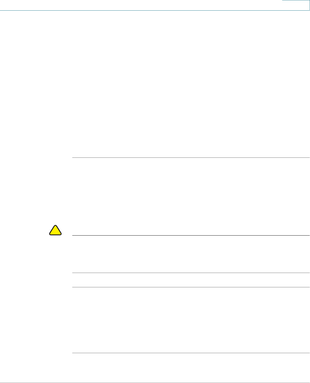
Device Management
Configuration Management
Cisco ISA500 Series Integrated Security Appliance Administrator Guide 296
10
STEP 3 To restore the settings from a saved configuration file on a USB device, perform
the following steps:
a. Insert the USB device into the USB interface on the back panel of your security
appliance. The USB device is automatically mounted once you insert it.
b. In the USB -> Mount/Unmount area, make sure that the USB Driver Status
shows as “UP” when you use the USB device to manage the configurations.
c. In the USB -> Select the upgrade file from your dard dick area, all saved
configuration files located on the USB device appears in the list. Select a
configuration file, and then click Restore.
d. If the configurantion file is encrpted, the Encryption window opens. Enter the
password in the Key field, and then click OK.
e. The security appliance automatically reboots with the saved settings of the
selected configuration file.
Reverting to the Factory Default Settings
To revert your security appliance to the factory default settings, you can press and
hold the RESET button on the back panel for minimal three seconds, or use the
Revert to Factory Default Settings feature.
!
CAUTION The Revert To Factory Default Settings operation will wipe out the current settings
used on your security appliance (including the imported certificates). We
recommmend that you save the current settings before reverting to the factory
default settings.
STEP 1 Click Device Management -> Firmware and Configuration -> Configuration.
The Configuration window opens.
STEP 2 In the Backup/Restore Settings -> Revert To Factory Default Settings area,
click Default.
STEP 3 The security appliance automatically reboots with the factory default settings.
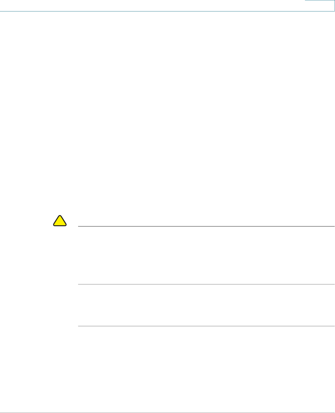
Device Management
Firmware Management
Cisco ISA500 Series Integrated Security Appliance Administrator Guide 297
10
Firmware Management
You can perform the following tasks to maintain the firmwares.
•View the firmware status. See Viewing the Firmware Information,
page 297.
•Check periodically for new firmwares. See Checking for New Firmwares,
page 298.
•Upgrade the firmware. See Upgrading the Firmware, page 299.
•Switch to the secondary firmware through the Configuration Utility. See
Using the Secondary Firmware, page 300.
•Auto fall back to the secondary firmware. See Firmware Auto Fall Back
Mechanism, page 301
•Use the Rescue mode to recover the system. See Using the Rescue Mode
to Recover the System, page 302
•Reboot the security appliance. See Rebooting the Security Appliance,
page 302.
!
CAUTION During a firmware upgrade, do NOT try to go online, turn off the device, shut down
the PC, remove the cable, or interrupt the process in anyway until the operation is
complete. This process should take several minutes or so including the reboot
process. Interrupting the upgrade process at specific points when the flash is
being written to can corrupt the flash memory and render the security appliance
unusable.
Viewing the Firmware Information
STEP 1 Click Device Management -> Firmware and Configuration -> Firmware.
The Firmware window opens.
STEP 2 The Network -> Status area, the following firmare information is displayed:
•Primary Firmware Version: The version of the primary firmware that you are
using.

Device Management
Firmware Management
Cisco ISA500 Series Integrated Security Appliance Administrator Guide 298
10
•Secondary Firmware Version: The version of the secondary firmware that
you used previously.
•Link to Release Note: Click the link to find the release notes for all available
firmwares.
•Time At Which Last Query was made: The time at which last query for the
new firmware was made.
•Latest Image Available: The latest version of the available firmware on the
IDA server after your query. This option will not display anything if the
firmware currently used on your security appliance is the lastest one.
STEP 3 If a newer version than your current one is available, you can perform one of the
following actions:
•To upgrade the firmware and keep using the current settings, click Upgrade.
When the operation is complete, the security appliance automatically
reboots with the previous settings that were in use.
•To upgrade the firmware and revert to the factory default settings, click
Upgrade & Factory Reset. When the operation is complete, the security
appliance automatically reboots with the factory default settings.
Checking for New Firmwares
The security appliance uses a built-in IDA client to query and upgrade the
firmware. The IDA client connects to Cisco’s IDA sever through the Internet. This
feature requires an active WAN connection.
STEP 1 Click Device Management -> Firmware and Configuration -> Firmware.
The Firmware window opens.
STEP 2 In the Network -> Check For New Firmware & Download area, enter the
following information to check new firmware from the IDA server periodically.
•Check Periodically: Check this box to automatically check for new
firmwares on a weekly basis.
•User Name: Displays the user name of your registered CCO account to log
into the IDA server for downloading the new firmware. To configure the CCO
account, go to the Device Management -> CCO Account page. See
Configuring the CCO Account, page 331.

Device Management
Firmware Management
Cisco ISA500 Series Integrated Security Appliance Administrator Guide 299
10
STEP 3 Click Save to save your settings.
STEP 4 Click Check Now to immediately check whether new firmware is available on the
IDA server.
If a new firmware is available, the version of the new firmware is displayed in the
Latest Image Available area.
Upgrading the Firmware
You can manually upgrade the firmware from your local PC or a USB device.
STEP 1 Click Device Management -> Firmware and Configuration -> Firmware.
The Firmware window opens.
STEP 2 To manually upgrade the firmware from your local PC, perform the following steps:
a. In the Network -> Firmware Upgrade area, click Browse to locate and select
the firmware image from your local PC.
b. To upgrade the firmware and keep using the current settings, click Upgrade.
When the operation is complete, the security appliance automatically reboots
with the previous settings that were in use.
c. To upgrade the firmware and revert to the factory default settings, click
Upgrade & Factory Reset. When the operation is complete, the security
appliance automatically reboots with the factory default settings.
STEP 3 To upgrade the firmware through a USB device, perform the following steps:
a. Insert the USB device with the firmware files into the USB interface on the back
panel of your security appliance. The USB device is automatically mounted
after you inserted it.
b. In the USB -> Mount/Unmount area, check the mounting status of the USB
device. Make sure that the USB Driver Status shows as “UP” when you use the
USB device to manage the firmware.
c. In the USB -> Backup/Restore Settings area, all firmware images located on
the USB device appears in the list.
Device Management
Firmware Management
Cisco ISA500 Series Integrated Security Appliance Administrator Guide 300
10
•To upgrade the firmware and keep using the current settings, select a
firmware image from the list and then click Upgrade. When the operation is
complete, the security appliance automatically reboots with the previous
settings you used.
•To upgrade the firmware and revert to the factory default settings, select a
firmware image from the list and then click Upgrade & Factory Reset. When
the operation is complete, the security appliance automatically reboots with
the factory default settings.
NOTE Wait while the firmware is upgrading.
1. Do NOT close the browser window.
2. Do NOT go online.
3. Do NOT turn off or power-cycle the security appliance.
4. Do NOT shutdown the computer.
5. Do NOT remove the cable.
Using the Secondary Firmware
If the primary firmware is not stable, you can manually set the secondary firmware
that was in use as the primary firmware. The original primary firmware will then
become the secondary firmware. After you switch to the secondary firmware, the
security appliance reboots with the saved settings. At this time, we recommend
that you revert your security appliance to the factory default settings.
!
CAUTION Do not try to swap the firmware if the secondary firmware is not present. Doing so
can cause the security appliance to not boot up.
STEP 1 Click Device Management -> Firmware and Configuration -> Firmware.
The Firmware window opens.
STEP 2 In the Swap Image area, click Switch to switch the secondary firmware to the
primary firmware.

Device Management
Firmware Management
Cisco ISA500 Series Integrated Security Appliance Administrator Guide 301
10
After you switch to the secondary firmware, the security appliance automatically
reboots with the saved settings.
Firmware Auto Fall Back Mechanism
The security appliance includes two firmware images in the same NAND flash to
provide an Auto Fall Back mechanism so that the security appliance can
automatically switch to the secondary firmware when the primary firmware
occurs a CRC (Cyclic Redundancy Check) Error or cannot boot up successfully for
five times.
The Auto Fall Back mechanism operates as follows:
1. When the security appliance tries to boot up with the primary firmware, the
Bootloader checks the CRC of the primary firmware.
2. If the primary firmware occurs a CRC Error or a Boot Failure, the Bootloader will
switch to the secondary firmware and check the CRC for the secondary
firmware.
•CRC Error: An error that the firmware cannot pass the CRC validation.
Downloading an incomplete firmware or incompletely writing the firmware
to the flash may cause the CRC error.
•Boot Failure: A failure that the firmware cannot boot up successfully for five
times. Booting up successfully means that the system boots to the login
shell.
3. If the secondary firmware occurs a CRC Error or a Boot Failure, the Rescue
mode starts up. In the Rescue mode, the security appliance works as a TFTP
server. You can use a TFTP client to upload a firmware image to upgrade. The IP
address of the TFTP server is 192.168.1.1. For more information about the
Rescue mode, see Using the Rescue Mode to Recover the System,
page 302.

Device Management
Log Management
Cisco ISA500 Series Integrated Security Appliance Administrator Guide 302
10
Using the Rescue Mode to Recover the System
When the system booting problem or device error occurs, or the system has a
problem, the POWER/SYS LED lights amber color. Follow these procedures to
start up the Rescue mode directly and then recover the system.
STEP 1 Press and hold the RESET button on the back panel of your security appliance for
minimal three seconds and turn on the power switch simutaneously, the Rescue
mode starts up.
STEP 2 In the Rescue mode, the security appliance works as a TFTP server. You can use a
TFTP client to upload the firmware image to upgrade. The IP address of the TFTP
server is 192.168.1.1.
STEP 3 The security appliance will upgrade the firmware after you uploaded the image.
This process should take several minutes or so including the reboot process.
During firmware upgrade, do NOT try to go online, turn off the device, shut down
the PC, interrupt the process, or remove the cable in anyway until the operation is
complete.
When the POWER/SYS lights green color, the system operates normally.
Rebooting the Security Appliance
STEP 1 Click Device Management -> Firmware and Configuration -> Firmware.
The Firmware window opens.
STEP 2 In the Reboot area, click Reboot to reboot the security appliance.
Log Management
The security appliance maintains the event logs for tracking potential security
threats. Use the Loggings pages to view the event logs, configure the log settings
and log facilities. It includes the following sections:
•Configuring the Log Settings, page 303
•Configuring the Log Facilities, page 305

Device Management
Log Management
Cisco ISA500 Series Integrated Security Appliance Administrator Guide 303
10
•Viewing the Logs, page 306
Configuring the Log Settings
STEP 1 Click Device Management -> Loggings -> Log Settings.
The Log Settings window opens.
STEP 2 In the Log Settings area, enter the following information:
•Log: Click On to enable the Log feature, or click Off to disable it.
•Log Buffer Size: If you enable the Log feature, specify the size of the local
log buffer. The default value is 409600 bytes.
STEP 3 In the System Logs area, specify the types of system events to be logged.
•All Unicast Traffic: Click On to log all unicast packets directed to the
security appliance. By default, all unicast packets are not logged.
•All Broadcast/Multicast Traffic: Click On to log all broadcast or multicast
packets directed to the security appliance. By default, all broadcast or
multicast packets are not logged.
STEP 4 In the Email Alert area, specify the syslogs to be sent on schedule.
•Email Alert: Shows if the Syslog Email is enabled or disabled.
•From Email Address: The email address of the SMTP email account to send
the logs.
•Send to Email Address: The email address of the SMTP email account to
receive the logs.
•SMTP Server: The IP address or Internet name of the SMTP server.
•SMTP Authentication: Shows if the SMTP authentication is enabled or
disabled.
NOTE The above email account settings for Syslog Email are read only. To
enable the Syslog Email feature and configure the email account
settings, click the link or go to the Device Management -> Email Alert
Settings page. See Configuring the Email Alert Settings, page 316.

Device Management
Log Management
Cisco ISA500 Series Integrated Security Appliance Administrator Guide 304
10
•Mail Subtitle: Enter the subtitle that is displayed in the email. For example, if
you set the device name as the subtitle, the receiver of the alert email can
recognize quickly what device the logs or alerts are coming from.
•Severity: Choose the severity level of the syslogs that you want to send.
For example: If you select Critical, all log messages listed under the Critical,
Emergency, and Alert categories are sent.
•Send Email Logs on Schedule: Specify the schedule to send the syslogs.
-Unit: Choose the period of time that you want to send the syslogs.
Hourly: Sends the syslogs on an hourly basis.
Daily: Sends the syslogs at specific time of every day. If you choose this
option, specify the time to send the syslogs in the Time field.
Weekly: Sends the syslogs on a weekly basis. If you choose this option,
specify the day of the week in the Day field and the time in the Time field.
-Day: If syslogs are sent on a weekly basis, choose the day of the week
-Time: Choose the time of day when syslogs should be sent.
Severity Levels Description
Emergency (level
0, highest severity)
System unusable. Syslog definition is LOG_EMERG.
Alert (level 1) Immediate action needed. Syslog definition is
LOG_ALERT.
Critical (level 2) Critical conditions. Syslog definition is LOG_CRIT.
Error (level 3) Error conditions. Syslog definition is LOG_ERR.
Warning (level 4) Warning conditions. Syslog definition is
LOG_WARNING.
Notification (level
5)
Normal but significant conditions. Syslog definition
is LOG_NOTICE.
Information (level
6)
Informational messages only. Syslog definition is
LOG_INFO.
Debug (level 7,
lowest severity)
Debugging messages. Syslog definition is
LOG_DEBUG.

Device Management
Log Management
Cisco ISA500 Series Integrated Security Appliance Administrator Guide 305
10
STEP 5 In the Remote Logs area, specify the logs to be saved to a remote syslog server.
•Remote Logs: Click On to save the syslogs to the specified remote syslog
server, or click Off to disable it.
•Syslog Server: Enter the IP address of the remote syslog server that runs a
syslog daemon.
•Severity: Choose the severity level of the logs that you want to save to the
remote syslog server.
For example: If you select Critical, the log messages listed under the Critical,
Emergency, and Alert categories are saved to the remote syslog server.
STEP 6 In the Local Log area, specify the logs to be saved to the local syslog daemon.
•Severity: Choose the severity level of the logs that you want to save to the
local syslog daemon.
For example: If you select Critical, all log messages listed under the Critical,
Emergency, and Alert categories are saved to the local syslog daemon.
STEP 7 Click Save to apply your settings.
Configuring the Log Facilities
A variety of events can be captured and logged for review. These logs can be
saved to the local syslog daemon or to a specified remote syslog server, or be
emailed to a specified email address.
To save the logs that are generated by the log facilities, you first need to enable
the Log feature, set the log buffer size, and specify the Email Alert, Remote Log,
and Local Log settings.
STEP 1 Click Device Management -> Loggings -> Logs Facility.
The Log Facility window opens. The supported log facilities are listed in the table.
STEP 2 Specify the actions for the logs generated by the log facilities:
•Email Alert: Check the box at the left side of the Email Alert heading to
enable the email alert setting for all log facilities, or check the box for a log
facility to enable the email alert settings for the selected log facility.
Device Management
Log Management
Cisco ISA500 Series Integrated Security Appliance Administrator Guide 306
10
If you enable this feature, the logs that belong to the selected facilities and
match up with the specified severity level for Email Alert can be sent to the
specified email address.
•Remote Log: Check the box at the left side of the Remote Log heading to
enable the remote log settings for all log facilities, or check the box of a log
facility to enable the remote log settings for the selected log facility.
If you enable this feature, the logs that belong to the selected facilities and
match up with the specified severity level for Remote Log can be saved to
the specified remote syslog server.
•Local Log: Check the box at the left side of the Local Log heading to enable
the local log settings for all log facilities, or check the box of a log facility to
enable the local log settings for the selected log facility.
If you enable this feature, the logs that belong to the selected facilities and
match up with the specified severity level for Local Log can be saved to the
local syslog daemon.
NOTE For more information about the Email Alert, Remote Log, and Local Log
settings, see Configuring the Log Settings, page 303.
NOTE The logs that belong to the unselected log facilities, or the logs that
belong to the selected log facilities but cannot match up with the
specified severity settings will be dropped.
STEP 3 Click Save to apply your settings.
Viewing the Logs
Use the View Logs page to view the syslogs for the specified severity level, the
log facility, or the source and destination IP address.
STEP 1 Click Device Management -> Loggings -> View Logs.
The View Logs window opens.
STEP 2 Specify the logs to be viewed:

Device Management
Managing the Security License
Cisco ISA500 Series Integrated Security Appliance Administrator Guide 307
10
•Log Severity: Choose the log severity level to filter the logs.
For example: If you select Critical, all logs listed under the Critical,
Emergency, and Alert categories can be viewed.
•Log Facility: Choose the log facility to filter the logs. All logs that belong to
the selected facility and match up with the specified severity settings can be
viewed.
•Source IP: Enter the source IP address to filter the logs. All logs that match
up with this source IP address can be viewed.
•Destination IP: Enter the destination IP address to filter the logs. All logs that
match up with this destination IP address can be viewed.
STEP 3 Click Query.
STEP 4 The query outputs are displayed in the Logs table. The logs can be sorted by
clicking the cellheading in the table. By default, the logs are sorted by the time.
For example, if you click Severity, the logs are sorted by the severity level in
ascending sequence. Double click Severity, the logs are sorted by the severity
level in descending sequence.
STEP 5 You can specify how many logs are displayed in the table per page. If one page
cannot show all logs, use the navigation buttons to switch among the pages.
STEP 6 Click the >> button and then click Clear All Local Logs to clean up all logs saved
in the local syslog daemon.
Managing the Security License
Use the License Management page to manage the security license. The security
license is valid for one year or three years depending on the bundle type. The
security services that provide protection against worms, attacks, and malware are
activated by the security license. It includes the following sections:
•Checking the License Status, page 308
•Renewing the Security License, page 309

Device Management
Managing the Security License
Cisco ISA500 Series Integrated Security Appliance Administrator Guide 308
10
Checking the License Status
STEP 1 Click Device Management -> License Manaagement.
The License Management window opens. The following information of the
security license is displayed.
•Feature: The security license name.
•Status: The security license status. The security license cannot be
transferred or revoked once it is licensed.
•Seats Available: The number of SSL VPN users supported by the security
license. The ISA550 and ISA550W supports 25 SSL VPN users. The ISA570
and ISA570W supports 50 SSL VPN users.
•Expiration: The date on which the security license expires, in MM/DD/YYYY
format. For example: 12/31/2012.
STEP 2 To check the device credential information, click Device Credentials.
The Device Credentials window opens. The device credential information is
requested by Cisco sales or support for licensing purpose.
STEP 3 Click Email Alert Settings, the Email Alert Settings window opens.
You can see the following settings of the License Expiration Alert. We recommend
that you enable the License Expiration Alert feature so that the system can send an
alert email to remind the user to renew the security license before it expires.
•Email Alert: Shows if the License Expiration Alert feature is enabled or
disabled.
•From Email Address: The email address to send the compressed file.
•Send to Email Address: The email address to receive the compressed file.
•SMTP Server: The IP address of the SMTP server.
•SMTP Authentication: Shows if the SMTP authentication is enabled or
disabled. If you enable SMTP authentication, the user name and password
are required to login the SMTP server.
•Alert When it is: The number of days before the license expires to send the
alert message.

Device Management
Managing the Security License
Cisco ISA500 Series Integrated Security Appliance Administrator Guide 309
10
NOTE To send the alert email for license expiration events, you first need to
enable the License Expiration Alert feature and configure the email
account settings in the Email Alert Setting page. Click the link or go
to the Device Management -> Email Alert Settings page to do this.
See Configuring the Email Alert Settings, page 316.
Renewing the Security License
Perform the following steps to renew the security license before it expires.
STEP 1 Contact your Cisco reseller to purchase a new license.
STEP 2 Launch the the Configuration Utility and login, go to the Device Management ->
License Manaagement page.
STEP 3 Click Renew.
The Install License window opens.
STEP 4 The license can be a license code (PAK) or a license file downloaded from
cisco.com. Choose the license type from the License Type drop-down list:
•License Code (PAK) from cisco.com: Automatically retrieves and installs
the license on the security appliance from the Cisco server. If you choose
this option, enter the following credential information. These credentials are
required to authenticate to the Cisco server.
-License Code: Enter the license code (PAK).
-Cisco.com Login: Enter the user name of your CCO account to log into
Cisco.com.
-Cisco.com Password: Enter the password of your CCO account to log
into Cisco.com.
-Email Address: Enter the registered email address to receive the PAK.
•License File Download from cisco.com: Installs the security license that
was previously downloaded to your PC. If you choose this option, click
Browse to locate and select the license file from your PC.

Device Management
Managing the Certificates for Authentication
Cisco ISA500 Series Integrated Security Appliance Administrator Guide 310
10
NOTE Make sure that the security appliance is set to the current time, or the
license will not install properly.
STEP 5 After you finish entering the information in the required fields, click Validate
License.
After the license is renewed, the expiration date of the security license is updated
immediately.
Managing the Certificates for Authentication
Use the Certificate Management page to manage the certificates for
authentication. It includes the following sections:
•Viewing the Certificate Status, page 310
•Managing the Certificates, page 311
Viewing the Certificate Status
STEP 1 Click Device Management -> Certificate Management.
The Certificate Management window opens. All existing certificates are listed in
the table. The following certificate information is displayed:
•Certificate: The certificate name.
•Type: The certificate type. The security appliance supports three types of
certificates: Certificate Signing Request (CSR), Local Certificate, and CA
Certificate.
-Certificate Signing Request (CSR): A certificate request generated by
your security appliance that needs to be sent to the Certificate Authority
(CA) for signing. CSR contains all the information required to create your
digital certificate.

Device Management
Managing the Certificates for Authentication
Cisco ISA500 Series Integrated Security Appliance Administrator Guide 311
10
-Local Certificate: The local certificate is issued by a trusted CA, and is
involved in the applications like remote management and SSL VPN. To
use a local certificate, you must first request a certificate from the CA and
then import the certificate on your security appliance.
-CA Certificate: The CA certificate is issed by intermediate CAs, such as
GoDaddy or VeriSign. The CA certificate is used to verify the validity of
certificates generated and signed by the CA.
STEP 2 Click the Detail button to view the detailed certificate information.
Managing the Certificates
Perform the following tasks to manage different types of certificates:
•To export a local certificate or a CSR to your PC, check the box and click
Download. See Exporting the Certificates to Local PC, page 312.
Certificate
Types
Details
CA Certificate
or Local
Certificate
•Name: Name used to identify this certificate.
•Issuer: Name of the CA that issued the
certificate.
•Subject: Name which other organizations will
see as the holder (owner) of this certificate.
•Serial Number:Serial number maintained by
the CA and used for identification purposes.
•Valid From: Date from which the certificate is
valid.
•Expires On: Date on which the certificate
expires. It is advisable to renew the certificate
before it expires.
Certification
Signing
Request (CSR)
•Name: Name used to identify this CSR.
•Subject: Name which other organizations will
see as the holder (owner) of this certificate.

Device Management
Managing the Certificates for Authentication
Cisco ISA500 Series Integrated Security Appliance Administrator Guide 312
10
•To export a local certificate or a CSR to a mounted USB device, check the
box and click Export to USB. See Exporting the Certificates to a USB
Device, page 313.
•To import a CA certificate or a local certificate from your PC, click Import.
See Importing the Certificates from Your Local PC, page 313.
•To import a CA certificate or a local certificate from a mounted USB device,
click Import from USB. See Importing the Certificates from a Mounted
USB Device, page 314.
•To import a signed certificate for a CSR from your PC, click Upload. See
Importing the Signed Certificate for CSR from Your Local PC, page 314.
•To generate a CSR, click New Signing Request. See Generating New
Certificate Signing Requests, page 315.
•To delete a certificate or a CSR, check the box and click Delete.
•To delete multiple entries, check the boxes of multiple entires and click
Delete Selection.
Exporting the Certificates to Local PC
You can export a local certificate or a CSR to your local PC. The CA certificate is
not allowed to export.
STEP 1 Click Device Management -> Certificate Management.
The Certificate Management window opens.
STEP 2 To export a local certificate or a CSR to your local PC, click Download.
•If you are downloading a CSR, the Download Certificate Signing Request
window opens. Click Download, the certificate file will be saved in .PEM
format.
•If you are downloading a local certificate, the Download Certificate window
opens. Enter the certificate management password in the Enter Export
Password field, and then click Download. The certificate file will be saved
in .p12 format.

Device Management
Managing the Certificates for Authentication
Cisco ISA500 Series Integrated Security Appliance Administrator Guide 313
10
Exporting the Certificates to a USB Device
To export a local certificate or a CSR to a USB device, you first need to insert the
USB device into the USB interface on the back panel of your security appliance.
The USB device is automatically mounted once you insert it. The CA certificate is
not allowed to export.
STEP 1 Click Device Management -> Certificate Management.
The Certificate window opens.
STEP 2 To export a local certificate or a CSR to the USB device, click Export to USB.
•If you are downloading a CSR, the Export Certificate Signing Request to USB
window opens. Click Export. The CSR file will be saved on the mounted USB
device in .PEM format.
•If you are downloading a local certificate, the Export Certificate to USB
window opens. Enter a password in the Enter Export Password field to
protect the certificate file and then click Export. The certificate file will be
saved on the mounted USB device in .p12 format.
Importing the Certificates from Your Local PC
You can import a local or CA certificate from your local PC.
STEP 1 Click Device Management -> Certificate Management.
The Certificate window opens.
STEP 2 To import a local or CA certificate from your local PC, click Import.
The Import Certificates window opens.
STEP 3 Enter the following information:
•Import a local end-user certificate with private key from a PKCS#12
(.p12) encoded file: If you choose this option, enter the certificate name in
the Certificate Name field and the protection password in the Import
Password field, click Browse to locate and select a local certificate file from
your local PC, and then click Import.

Device Management
Managing the Certificates for Authentication
Cisco ISA500 Series Integrated Security Appliance Administrator Guide 314
10
•Import a CA certificate from a PEM (.pem or .crt) encoded file: If you
choose this option, click Browse to locate and select a CA certificate file
from your local PC, and then click Import.
Importing the Certificates from a Mounted USB Device
To import local or CA certificates from a USB device, you first need to insert the
USB device into the USB interface on the back panel of your security appliance.
The USB device is automatically mounted once you insert it.
STEP 1 Click Device Management -> Certificate Management.
The Certificate window opens.
STEP 2 To import a local or CA certificate from the USB device, click Import from USB.
The Import Certificates window opens. All available local certificates and CA
certificates appear in the list.
STEP 3 Check the box of the certificate file, enter the certificate name in the Certificate
Name field and the protection password in the Import Password field, and then
click Import.
Importing the Signed Certificate for CSR from Your Local PC
You can upload a signed certificate for a CSR from your local PC.
STEP 1 Click Device Management -> Certificate Management.
The Certificate window opens.
STEP 2 To import a signed certificate for CSR from your local PC, click Upload.
The Upload Certificate window opens.
STEP 3 Click Browse to locate and select the signed certificate file for the CSR from your
local PC, and then click Upload.
NOTE The signed certificate file should be PEM(.pem or .crt) encoded.

Device Management
Managing the Certificates for Authentication
Cisco ISA500 Series Integrated Security Appliance Administrator Guide 315
10
Generating New Certificate Signing Requests
STEP 1 Click Device Management -> Certificate Management.
The Certificate Management window opens.
STEP 2 Click New Signing Request to generate a new certificate signing request.
The Generate Certificate Signing Request window opens.
STEP 3 Enter the following information:
•Certificate Alias: Enter an alias name for the certificate.
•Country Name: Choose the country from the drop-down list.
•State or Province Name: Enter the state or province name of your location.
•Locality Name: Enter the address of your location.
•Organization Name: Enter your organization name.
•Organization Unit Name: Enter your department name.
•Common Name: Enter the common name for the certificate.
•E-mail Address: Enter your email address.
•Subject Distinguished Name: After you enter the above information, the
Distinguished Name (DN) is created in this field.
•Subject Key Type: Displays the signature algorithm (RSA) used to sign the
certificate. RSA is a public key cryptographic algorithm used for encrypting
data.
•Subject Key Size: Choose the length of the signature: 502 bits, 1024 bits, or
2048 bits.
STEP 4 Click Generate to create a certificate signing request file.
After you generate a certificate signing request file, you need to export the CSR
file to your local PC for submission to a Registration or CA. The CSR file will be
saved in .PEM format. You can change the file name that you download as needed.

Device Management
Configuring the Email Alert Settings
Cisco ISA500 Series Integrated Security Appliance Administrator Guide 316
10
Configuring the Email Alert Settings
Use the Email Alert Settings page to centrally configure how to send the alert
messages to the operator or administrator for specific events or behaviors that
may impact the performance, operation, and security of your security appliance,
or for debugging purposes.
STEP 1 Click Device Management -> Email Alert Settings.
The Email Alert Settings window opens.
STEP 2 Enter the following information:
•SMTP Server: Enter the IP address or Internet name of the SMTP server.
•SMTP Authentication: If the SMTP server requires authentication before
accepting the connections, click On to enable SMTP authentication. Users
need to provide the SMTP account information for authentication.
•Account: Enter the user name of the SMTP email account.
•Password: Enter the password of the SMTP email account.
•From Email Address: Enter the email address to send the alert messages.
•To Emai l A ddre ss: Enter the email address to receive the alert messages.
This email address is used to receive all alert emails for all categories. If you
want the alert emails for different categories to be sent to different email
accounts, uncheck the box of Use this address for all alert, and then
separately specify the email address to receive the alert messages for each
category in the To Email Address column.
•Category: The security appliance sends the alert messages if events or
behaviors for the specific category are detected. To enable the email alert
settings for a category, check the Enable box and then configure the
corresponding settings.

Device Management
Configuring the Email Alert Settings
Cisco ISA500 Series Integrated Security Appliance Administrator Guide 317
10
Alert
Category
Description Configurations
WAN UP/
DOWN
Alert
Sends an alert email if the
WAN interface link is UP or
DOWN.
To Email Address: Enter
the email address to
receive the alert messages.
Alert Interval: Specify how
often in minutes the
security appliance sends
the alert messages for
WAN down or up events.
IPSec
Alert
Sends an alert email if the
IPSec VPN tunnel
negotiation fails.
To Email Address: Enter
the email address to
receive the alert messages.
IPS Alert Sends an alert email if an
attack is detected over the
specified email alert
threshold for IPS categories
or IM and P2P applications.
You first need to enable the
IPS service and specify the
email alert thresholds for
the IM and P2P Blocking
feature and/or the IPS
Policy and Protocol
Inspection feature. See
Intrusion Prevention
Service, page 214.
To Email Address: Enter
the email address to
receive the alert messages.
Firmware
Upgrade
Alert
Sends an alert email if a
new firmware is found after
automatically checking the
firmware.
To Email Address: Enter
the email address to
receive the alert messages.

Device Management
Configuring the Email Alert Settings
Cisco ISA500 Series Integrated Security Appliance Administrator Guide 318
10
License
Expiration
Alert
Sends an alert email at x
days before the security
license expires. x is
configurable.
To Email Address: Enter
the email address to
receive the alert messages.
Alert When it is: Enter the
number of days before the
license expires to send the
alert message.
CPU
Overload
Alert
Sends an alert email if the
CPU utilization is higher
than the threshold.
To Email Address: Enter
the email address to
receive the alert messages.
CPU Threshold Setting:
Enter the threshold value of
CPU utilization.
Debug
Support
Sends the debug support
package (*.zip) that is
generated by the System
Diagnostics settings for
debugging purposes.
To specify the contents to
be compressed in a file in
the zip format, see System
Diagnostics, page 327.
To Email Address: Enter
the email address to
receive the alert messages.
Anti-Virus
Alert
Sends an alert email if virus
is detected.
You first need to enable the
Anti-Virus service and
specify the protocols to
scan for viruses. For more
information, see Anti-Virus,
page 220.
To Email Address: Enter
the email address to
receive the alert messages.
Alert Interval: Specify how
often, in minutes, the
security appliance sends
the alert messages for virus
events.
Alert
Category
Description Configurations

Device Management
Configuring the RADIUS Servers
Cisco ISA500 Series Integrated Security Appliance Administrator Guide 319
10
STEP 3 Click Save to apply your settings.
Configuring the RADIUS Servers
Use the RADIUS Servers page to configure the RADIUS servers that are used to
authenticate the users who try to access your network resources. A RADIUS
group includes a primary RADIUS server and a backup RADIUS server. The
security appliance predefines three RADIUS groups.
STEP 1 Click Device Management -> RADIUS Servers.
The RADIUS Servers window opens. All predefined RADIUS groups are listed in
the table.
STEP 2 To edit the settings of the predefined RADIUS group, click Edit in the
Configuration column.
After you click Edit, the RADIUS Group - Edit window opens.
STEP 3 Enter the following information:
•Primay RADIUS Server IP: Enter the IP address of the primary RADIUS
server.
•Primay RADIUS Server Port: Enter the port number on the primary RADIUS
server that is used to send the RADIUS traffic. The default is 1812.
•Primay RADIUS Server Pre-shared Key: Enter the pre-shared key that is
configured on the primary RADIUS server.
Syslog
Email
Send the syslog messages
on schedule to the
specified email receiver.
To specify the syslogs to be
sent, see Configuring the
Log Settings, page 303.
To Email Address: Enter
the email address to
receive the alert messages.
Alert
Category
Description Configurations

Device Management
Configuring the Time Zone
Cisco ISA500 Series Integrated Security Appliance Administrator Guide 320
10
•Secondary RADIUS Server IP: Enter the IP address of the secondary
RADIUS server.
•Secondary RADIUS Server Port: Enter the port number on the secondary
RADIUS server that is used to send the RADIUS traffic. The default is 1812.
•Secondary RADIUS Server Pre-shared Key: Enter the pre-shared key that
is configured on the secondary RADIUS server.
STEP 4 Click OK to save your settings.
STEP 5 Repeat the above steps to edit the settings for other RADIUS groups if needed.
STEP 6 Click Save to apply your settings.
Configuring the Time Zone
Use the Time Zone / Clock Settings page to manually configure the time zone and
clock settings, or to dynamically synchronize the time zone and clock settings with
the Network Time Protocol (NTP) server.
STEP 1 Click Device Management -> TimeZone / Clock Settings.
The Time Zone and Clock Settings window opens.
STEP 2 Click Manual to manually set the date and time. Enter the values in the Date and
Time fields.
STEP 3 Click Dynamic to automatically synchronize the date and time with the NTP
server:
•Date/Time: Choose the time zone relative to Greenwich Mean Time (GMT).
•Automatically Adjust for Daylight Savings Time: Click On to automatically
adjust the time for Daylight Savings Time, or click Off to disable it.
•Use Default NTP Servers: Click this option to use the default Network Time
Protocol (NTP) server.

Device Management
Device Discovery
Cisco ISA500 Series Integrated Security Appliance Administrator Guide 321
10
•Use Custom NTP Servers: Click this option to use a custom NTP server.
Enter the IP addresses or domain names of up to two custom NTP servers in
the Server 1 Name/IP Address and Server 2 Name/IP Address fields. The
Server 1 is the primary NTP server and the Server 2 is the secondary NTP
server.
•Current Time: The current date and time sychronized with the configured
NTP server.
STEP 4 Click Save to apply your settings.
Device Discovery
The security appliance supports the following tools to discover the devices:
•UPnP, page 321
•Bonjour, page 322
•CDP, page 323
•LLDP, page 324
UPnP
UPnP (Universal Plug and Play) allows for automatic discovery of devices that can
communicate with your security appliance. The UPnP Portmap table displays the
port mapping entries of the UPnP-enabled devices that accessed your security
appliance.
STEP 1 Click Device Management -> Discovery -> UPnP.
The UPnP window opens.
STEP 2 Enter the following information:
•UPnP: Click On to enable UPnP, or click Off to disable UPnP. If UPnP is
disabled, the security appliance will not allow for automatic device
configuration.
•LAN: Choose an existing VLAN to which the UPnP information is
broadcasted and listened on.

Device Management
Device Discovery
Cisco ISA500 Series Integrated Security Appliance Administrator Guide 322
10
•Advertisement Period: Enter the value in seconds of how often the security
appliance broadcasts its UPnP information to all devices within range. The
default value is 1800 seconds.
•Advertisement Time to Live: Enter the value expressed in hops for each
UPnP packet. This is the number of steps a packet is allowed to propagate
before being discarded. Small values will limit the UPnP broadcast range.
The default value is 4.
STEP 3 Click Save to apply your settings.
STEP 4 After you enable UPnP, the information in the UPnP Portmap table will be refreshed
immediately. Or click Refresh to manually refresh the UPnP records in the table.
Bonjour
Bonjour is a service advertisement and discovery protocol. Bonjour only
advertises the default services configured on the security appliance when
Bonjour is enabled.
STEP 1 Click Device Management -> Discovery -> Bonjour.
The Bonjour window opens.
STEP 2 In the Bonjour Configuration area, click On to enable Bonjour, or click Off to
disable it. If you enable Bonjour, all default services are enabled.
STEP 3 In the Enabled Default Service area, the default enabled services are displayed.
The default services include CSCO-SB, HTTP, and HTTPS.
STEP 4 In the VLAN Association area, you can associate the VLANs for the default
services. The default services will only be visible to the hosts that belong to the
associated VLANs.
•Choose a VLAN from the Available VLANs drop-down list and then click
Apply. The VLANs associated to the default services are listed in the table.
•To dissociate the VLANs from the default services, check the boxes next to
the appropriate VLANs and click Delete.
•Click Reset to revert to the default settings.
STEP 5 Click Save to apply your settings.
Device Management
Device Discovery
Cisco ISA500 Series Integrated Security Appliance Administrator Guide 323
10
CDP
Cisco Discovery Protocol (CDP) is a device discovery protocol that runs on all
Cisco manufactured equipment. Each CDP enabled device sends periodic
messages to a multicast address and also listens to the periodic messages sent
by others in order to learn about neighboring devices and determine the status of
these devices. Use the CDP page to configure the settings to control CDP.
NOTE Enabling CDP is not recommended on the dedicated WAN port and the
configurable ports because they are connected to insecure networks.
STEP 1 Click Device Management -> Discovery -> CDP.
The CDP window opens.
STEP 2 In the CDP Configuration area, enter the following information:
•CDP: Choose one of the following options:
-Enable All: Enables CDP on all ports supported by the security
appliance.
-Disable All: Disables CDP on all ports supported by the security
appliance.
-Per Port: Configures CDP on selective ports.
•CDP Timer: Enter the value of the time interval between two successive
CDP packets sent by the security appliance.
•CDP Hold Timer: The hold timer is the amount of time the information sent
in the CDP packet should be cached by the device which receives the CDP
packet, after which the information is expires.
STEP 3 In the Enable CDP area, click On to enable CDP on each interface, or click Off to
disable CDP. This is required if you choose Per Port from the CDP drop-down list.
STEP 4 Click Save to apply your settings.

Device Management
Diagnosing the Device
Cisco ISA500 Series Integrated Security Appliance Administrator Guide 324
10
LLDP
The Link Layer Discovery Protocol (LLDP) enables network managers to
troubleshoot and enhance network management by discovering and maintaining
network topologies over multi-vendor environments. LLDP discovers network
neighbors by standardizing methods for network devices to advertise themselves
to other systems, and to store discovered information.
LLDP enables a device to advertise its identification, configuration, and
capabilities to neighboring devices that store the data in a Management
Information Base (MIB). The network management system models the topology of
the network by querying these MIB databases.
STEP 1 Click Device Management -> Discovery -> LLDP.
The LLDP window opens.
STEP 2 Click On to enable LLDP, or click Off to disable it. If you enable LLDP, the LLDP
neighbors are listed in the LLDP Neighbor table.
STEP 3 To view the detail of a LLDP neighbor, check the box and click Details.
STEP 4 To refresh the information in the LLDP Neighbor table, click Refresh.
STEP 5 Click Save to apply your settings.
Diagnosing the Device
Use the Diagnostics pages to access the configurations of the security appliance
and to monitor the overall network health. The following tools are supported to
diagnose your network.
•Ping, page 325
•Tracert, page 325
•DNS Lookup, page 326
•Packet Capture, page 326
•System Diagnostics, page 327

Device Management
Diagnosing the Device
Cisco ISA500 Series Integrated Security Appliance Administrator Guide 325
10
NOTE These features require an active WAN connection.
Ping
Use the Ping page to test the connectivity between the security appliance and a
connected device on the network.
STEP 1 Click Device Management -> Diagnostics -> Ping.
The Ping window opens.
STEP 2 Enter the following information:
•IP or URL Address: Enter the IP address or URL to ping.
•Packet Size: Enter the packet size in the range of 32 to 65500 bytes to ping.
The security appliance will send the packet with the specified size to the
destination.
•Ping Time: Enter the times to ping. The security appliance will send the
packet for specific times to check the connectivity with the destination IP
address.
STEP 3 Click Start Ping to ping the IP address or the URL, or click Stop Ping to stop
pinging.
Tracert
Use the Tracert page to view the route between the security appliance and a
destination.
STEP 1 Click Device Management -> Diagnostics -> Tracert.
The Tracert window opens.
STEP 2 Enter the following inforamtion:
•IP or URL Address: Enter the IP address or URL of the destination.
•Max Hops: Choose the maximum hop number.

Device Management
Diagnosing the Device
Cisco ISA500 Series Integrated Security Appliance Administrator Guide 326
10
STEP 3 Click Start Traceroute to trace the route of the IP address or URL, or click Stop
Traceroute to stop tracing.
DNS Lookup
Use the DNS Lookup page to retrieve the IP address of any server on the Internet.
STEP 1 Click Device Management -> Diagnostics -> DNS Lookup.
The DNS Lookup window opens.
STEP 2 Enter the IP address or domain name that you want to look up in the IP Address or
Domain Name field.
STEP 3 Click Run Lookup to query the server on the Internet. If the host or domain name
exists, you will see a response with the IP address.
STEP 4 Click Cleanup Result to clean up the querying result.
Packet Capture
Use the Packet Capture page to capture all packets that pass through a selected
interface.
STEP 1 Click Device Management -> Diagnostics -> Packet Capture.
The Packet Capture window opens.
STEP 2 Choose the network that you want to capture the packets from the Select
Network drop-down list.
STEP 3 Click Start to start capturing the packets, click Stop to stop capturing, or click
Download to download the captured packets.

Device Management
Diagnosing the Device
Cisco ISA500 Series Integrated Security Appliance Administrator Guide 327
10
System Diagnostics
Use the Collect Diagnostics page to compress the contents like configuration files,
syslog files, and system status data into one file in the zip format, and send the
compressed file to the specified email account for system diagnosis. You can set a
password to protect the compressed file for security purposes.
STEP 1 Click Device Management -> Diagnostics -> Collect Diagnostics.
The Collect Diagnostics window opens.
STEP 2 In the Content area, choose the contents that you want to use for diagnosing the
system. The selected files are compressed into one file in the zip format.
•Configuration File: Click On to compress the configuration files for system
diagnosis.
•Syslog File: Click On to compress the syslog files for system diagnosis.
•System Status: Click On to compress the system status data for system
diagnosis.
STEP 3 In the Password Protection area, you can set a password to secure the
compressed file.
•Password Protection: Click On to enable password protection, or click Off
to disable it.
•Password: If you enable the password protection, enter the password in this
field.
STEP 4 In the Email area, the email account settings for sending the compressed file are
displayed.
•Email Alert: Shows if the Debug Support Alert feature is enabled or
disabled.
•From Email Address: The email address to send the compressed file.
•Send to Email Address: The email address to receive the compressed file.
•SMTP Server: The IP address of the SMTP server.
•SMTP Authentication: Shows if the SMTP authentication is enabled or
disabled. If you enable SMTP authentication, the user name and password
are required to log into the SMTP server.
Device Management
Measuring and Limiting Traffic with the Traffic Meter
Cisco ISA500 Series Integrated Security Appliance Administrator Guide 328
10
NOTE To send the compressed file for system diagnosis, you first need to
enable the Debug Support Alert feature and configure the email
account settings in the Email Alert Setting page. Click the link or go
to the Device Management -> Email Alert Settings page to do this.
See Configuring the Email Alert Settings, page 316.
STEP 5 Click Save to apply your settings.
STEP 6 Click Send Now to send the compressed file to the specified email address
immediately.
Measuring and Limiting Traffic with the Traffic Meter
Traffic Meter allows you to measure and limit the traffic routed by the security
appliance. You can enable the traffic meter settings for both primary WAN and
secondary WAN (if applicable).
STEP 1 Click Device Management -> Traffic Meter -> Primary WAN Settings.
The Primary WAN Settings window opens.
NOTE To configure the traffic meter settings for the secondary WAN if applicable,
click Device Management -> Traffic Meter -> Secondary WAN Settings.
STEP 2 In the Enable Traffic Meter area, enter the following information:
•Enable Traffic Metering: Click On to enable the traffic metering on the
primary WAN port, or click Off to disable it. Enabling this feature on the
primary port will keep a record of the volume of traffic going from this
interface.
•Traffic Limit Type: Specify the restriction on the volume of data being
transferred through the primary WAN port.
-No Limit: The default option, where no limits on data transfer are
imposed.

Device Management
Measuring and Limiting Traffic with the Traffic Meter
Cisco ISA500 Series Integrated Security Appliance Administrator Guide 329
10
-Download Only: Limits the amount of download traffic. Enter the
maximum allowed data in Megabytes that can be downloaded for a given
month in the Monthly Limit field. Once the limit is reached, no traffic is
allowed from the WAN side.
-Both Directions: Calculates the traffic for both upload and download
directions. The traffic limit entered into the Monthly Limit field is shared
by both upload and download traffic. For example, for a 1 GB limit, if a 700
MB file is downloaded then the remaining 300 MB must be shared
between both upload and download traffic. The amount of traffic
downloaded will reduce the amount of traffic that can be uploaded and
vice-versa.
•Monthly Limit: Enter the volume limit that is applicable for this month. This
limit will apply to the type of direction (Download Only or Both Direction)
selected above.
•Increase this month limit by: Click On to temporarily increase the limit if the
monthly traffic limit has been reached, or click Off to disable it. If you enable
this feature, enter the amount of the increase in this field.
•This Month Limit: The data transfer limit applicable for this month that is the
sum of the values in the Monthly Limit field and the Increase this month
limit by field.
STEP 3 In the Traffic Counter area, enter the following information:
•Traffic Counter: Specify the action to be taken on the traffic counter.
-Restart Now: Choose this option and then click Save to reset the counter
immediately.
-Specific Time: Choose this option if you want the counter to restart at a
specified date and time, then enter the time in hours (HH) and minutes
(MM) and select the day of the month in the Reset Time field.
•Send email report before restarting counter: Click On to send an email
report before the traffic counter is reset, or click Off to disable it. This feature
requires that you enable the Email Alert feature in the Log Settings page. See
Log Management, page 302.
STEP 4 In the When Limit is Reached area, specify the action when the traffic limit is
reached.
•Traffic Block Status: Choose one of the following options:
-Block All Traffic: Blocks all traffic through the WAN interface when the
traffic limit is reached.

Device Management
Configuring the ViewMaster
Cisco ISA500 Series Integrated Security Appliance Administrator Guide 330
10
-Block All Traffic Except Email: Blocks all traffic except email through the
WAN interface when the traffic limit is reached.
•Send email alert: Click On to send an alert email to the specific email
account when the traffic limit is reached, or click Off to disable it. This feature
requires that you enable the Email Alert feature in the Log Settings page. See
Log Management, page 302.
STEP 5 In the Internet Traffic Statistics area, the following information is displayed if you
enable the traffic metering:
STEP 6 Click Save to apply your settings.
Configuring the ViewMaster
ViewMaster is a network monitoring and management protocol. If you enable
ViewMaster, the devices accept the HTTP or HTTPS connections with the Local
Management Agent that is embodied in the security appliance.
STEP 1 Click Device Management -> ViewMaster.
The ViewMaster window opens.
Start Date/Time The date on which the traffic meter was started or the last
time when the traffic counter was reset.
Outgoing Traffic
Volume
The volume of traffic in Megabytes that was uploaded
through this interface.
Incoming Traffic
Volume
The volume of traffic in Megabytes that was downloaded
through this interface.
Average per day The average volume of traffic that passed through this
interface.
% of Standard
Limit
The amount of traffic in percent that passed through this
interface against the monthly limit.
% of this
Month’s Limit
The amount of traffic in percent that passed through this
interface against this month’s limit (if the month’s limit has
been increased).

Device Management
Configuring the CCO Account
Cisco ISA500 Series Integrated Security Appliance Administrator Guide 331
10
STEP 2 Click On to enable ViewMaster, or click Off to disable it. By default, ViewMaster is
enabled.
STEP 3 Click Save to apply your settings.
Configuring the CCO Account
Use the CCO Account page to configure your registered CCO account. The CCO
account is used to log into Cisco.com for specific services. For example, if you
want to download the IPS signatures or automatically update the IPS signatures,
you are required to provide the CCO account information.
To register a CCO account on the Cisco.com, go to https:// tools.cisco.com/RPF/
register/register.do.
STEP 1 Click Device Management -> CCO Account.
The CCO Account window opens.
STEP 2 Enter the following information:
•User Name: Enter the name of your registered CCO account.
•Current Password: Enter the current password of your registered CCO
account.
•New Password: Enter a new password for the CCO account.
•Confirm New Password: Enter the new password again for confirmation.
STEP 3 Click Save to apply your settings.

Device Management
Configuring the Device Properties
Cisco ISA500 Series Integrated Security Appliance Administrator Guide 332
10
Configuring the Device Properties
Use the Device Properties page to configure the host name and domain name to
identify your security appliance on the network.
STEP 1 Click Device Management -> Device Properties.
The Device Properties window opens.
STEP 2 Enter the following information:
•Host Name: Enter the host name of your security appliance, which is
displayed on the network to identify your device.
•Domain Name: Enter an unique domain name to identify your network.
STEP 3 Click Save to apply your settings.
Configuring the Debug Settings
Use the Debug Setting page to enable the SSH version 2 server for debugging
purposes.
STEP 1 Click Device Management -> Debug Setting.
The Debug Setting window opens.
STEP 2 Click On to enable the SSH version 2 server for debugging, or click Off to disable
it.
This feature allows the engineers to use an unique console root password to log
into the security appliance for debugging operation. The root password expires in
24 hours, so you need to ask for a new password once it expires.
STEP 3 To set the root password for remote support, enter the password in the Remote
Support Password field.
STEP 4 Click Save to apply your settings.

A
Cisco ISA500 Series Integrated Security Appliance Administrator Guide 333
Troubleshooting
This chapter describes how to fix some common issues when you are using the
security appliance. It includes the following sections:
•Internet Connection, page 333
•Date and Time, page 336
•Pinging to Test LAN Connectivity, page 337
•Restoring Factory Default Settings, page 339
Internet Connection
Symptom: You cannot access the Configuration Utility from a PC on your LAN.
Recommended Actions:
STEP 1 Check the Ethernet connection between the PC and the security appliance.
STEP 2 Ensure that the IP address of your PC is on the same subnet as the security
appliance. If you are using the recommended addressing scheme, your PC’s
address should be in the range 192.168.1.100 to 192.168.1.200.
STEP 3 Check the IP address of your PC. If the PC cannot reach a DHCP server, some
versions of Windows and MacOS generate and assign an IP address. These auto-
generated addresses are in the range of 169.254.x.x. If your IP address is in this
range, check the connection from the PC to the security appliance and reboot your
PC.
STEP 4 If your IP address has changed and you don’t know what it is, reset the security
appliance to the factory default settings.

Troubleshooting
Internet Connection
Cisco ISA500 Series Integrated Security Appliance Administrator Guide 334
A
If you do not want to reset to factory default settings and lose your configuration,
reboot the security appliance and use a packet sniffer (such as Ethereal™) to
capture packets sent during the reboot. Look at the ARP packets to locate the LAN
interface address.
STEP 5 Launch your web browser and ensure that Java, JavaScript, or ActiveX is enabled.
If you are using Internet Explorer, click Refresh to ensure that the Java applet is
loaded. Close the browser and launch it again.
STEP 6 Ensure that you are using the correct login information. The factory default login
name is cisco and the password is cisco. Ensure that CAPS LOCK is off when
entering this information.
Symptom: The security appliance does not save my configuration changes.
Recommended Actions:
STEP 1 When entering configuration settings, click OK or Save before moving to another
page or tab; otherwise your changes are lost.
STEP 2 Click Refresh or Reload in the browser, which will clear a cached copy of the old
configuration.
Symptom: The security appliance cannot access the Internet.
Possible Cause: If you use dynamic IP addresses, your security appliance is not
requesting an IP address from the ISP.
Recommended Actions:
STEP 1 Launch your browser and determine if you can connect to an external site such as
www.cisco.com.
STEP 2 Launch the Configuration Utility.
STEP 3 Click Status -> Dashboard in the left hand navigation pane.
STEP 4 In the WAN Interface area, find the WAN1 Address. If 0.0.0.0 is shown, your
security appliance has not obtained an IP address from your ISP. See the next
symptom.

Troubleshooting
Internet Connection
Cisco ISA500 Series Integrated Security Appliance Administrator Guide 335
A
Symptom: The security appliance cannot obtain an IP address from the ISP.
Recommended Actions:
STEP 1 Turn off power to the cable or DSL modem.
STEP 2 Turn off the security appliance.
STEP 3 Wait 5 minutes, and then reapply power to the cable or DSL modem.
STEP 4 When the modem LEDs indicate that it has resynchronized with the ISP, reapply
power to the security appliance. If the security appliance still cannot obtain an ISP
address, see the next symptom.
Symptom: The security appliance still cannot obtain an IP address from the ISP.
Recommended Actions:
STEP 1 Click Networking -> WAN in the left hand navigation pane.
STEP 2 Click Edit.
The WAN - Add/Edit window opens.
STEP 3 Ask your ISP the following questions:
•What type of network addressing mode is required for your Internet
connection? In the IPv4 tab, choose the correct ISP connection type in the
IP Address Assignment drop-down list, and then enter the account
information as specified by the ISP.
•Is your ISP expecting you to login from a particular Ethernet MAC address?
If yes, in the IPv4 tab, choose Use the following MAC address from the
MAC Address Source drop-down list, and then enter the required MAC
address in the MAC Address field.
Symptom: The security appliance can obtain an IP address, but PC is unable to
load Internet pages.
Recommended Actions:

Troubleshooting
Date and Time
Cisco ISA500 Series Integrated Security Appliance Administrator Guide 336
A
STEP 1 Ask your ISP for the addresses of its designated DNS servers. Configure your PC
to recognize those addresses. For details, see your operating system
documentation.
STEP 2 On your PC, configure the security appliance to be its TCP/IP gateway.
Date and Time
Symptom: Date shown is January 1, 2000.
Possible Cause: The security appliance has not yet successfully reached a
network Time Server (NTS).
Recommended Actions:
STEP 1 If you have just configured the security appliance, wait at least 5 minutes, click
Device Management -> Time Zone / Clock Settings in the left hand navigation
pane.
STEP 2 Review the settings for the date and time.
STEP 3 Verify your Internet access settings.
Symptom: The time is off by one hour.
Possible Cause: The security appliance does not automatically adjust for
Daylight Savings Time.
Recommended Actions:
STEP 1 Click Device Management -> Time Zone / Clock Settings in the left hand
navigation pane.
STEP 2 Click On to enable the Automatically adjust for Daylight Savings Time feature.
STEP 3 Click Save to apply your settings.

Troubleshooting
Pinging to Test LAN Connectivity
Cisco ISA500 Series Integrated Security Appliance Administrator Guide 337
A
Pinging to Test LAN Connectivity
Most TCP/IP terminal devices and security appliances contain a ping utility that
sends an ICMP echo-request packet to the designated device. The device
responds with an echo reply. Troubleshooting a TCP/IP network is made very easy
by using the ping utility in your PC or workstation.
This section includes the following topics:
•Testing the LAN Path from Your PC to Your Security Appliance,
page 337
•Testing the LAN Path from Your PC to a Remote Device, page 338
Testing the LAN Path from Your PC to Your Security
Appliance
STEP 1 On your PC, click the Windows Start button, and then click Run.
STEP 2 Type ping <IP_address-> where <IP_address-> is the IP address of the security
appliance. Example: ping 192.168.1.1.
STEP 3 Click OK.
STEP 4 Observe the display:
•If the path is working, you see this message sequence:
Pinging <IP address-> with 32 bytes of data
Reply from <IP address->: bytes=32 time=NN ms TTL=xxx
•If the path is not working, you see this message sequence:
Pinging <IP address-> with 32 bytes of data
Request timed out
STEP 5 If the path is not working, test the physical connections between the PC and the
security appliance:
•If the LAN port LED is off, verify that the corresponding link LEDs are lit for
your network interface card and for any hub ports that are connected to your
workstation and security appliance.
STEP 6 If the path is still not up, test the network configuration:

Troubleshooting
Pinging to Test LAN Connectivity
Cisco ISA500 Series Integrated Security Appliance Administrator Guide 338
A
•Verify that the Ethernet card driver software and TCP/IP software are
installed and configured on the PC.
•Verify that the IP addresses for the security appliance and PC are correct
and on the same subnet.
Testing the LAN Path from Your PC to a Remote Device
STEP 1 On your PC, click the Windows Start button, and then click Run.
STEP 2 Type ping -n 10 <IP_address-> where -n 10 specifies a maximum of 10 tries and
<IP address-> is the IP address of a remote device such as your ISP’s DNS server.
Example: ping -n 10 10.1.1.1.
STEP 3 Click OK and then observe the display (see the previous procedure).
STEP 4 If the path is not working, do the following:
•Check that the PC has the IP address of your security appliance is listed as
the default gateway. (If the IP configuration of your PC is assigned by DHCP,
this information is not visible in your PC’s Network Control Panel.)
•Verify that the network (subnet) address of your PC is different from the
network address of the remote device.
•Verify that the cable or DSL modem is connected and functioning.
•Call your ISP and go through the questions listed in The security appliance
cannot obtain an IP address from the ISP.
•Ask your ISP if it rejects the Ethernet MAC addresses of all but one of your
PCs. Many broadband ISPs restrict access by allowing traffic from the MAC
address of only your broadband modem. Some ISPs additionally restrict
access to the MAC address of just a single PC connected to that modem. If
this is the case, configure your security appliance to clone or spoof the MAC
address from the authorized PC. See Configuring the WAN, page 101.

Troubleshooting
Restoring Factory Default Settings
Cisco ISA500 Series Integrated Security Appliance Administrator Guide 339
A
Restoring Factory Default Settings
To restore the factory default settings, take one of the following actions:
•Launch the Configuration Utility and login. Click Device Management ->
Firmware and Configuration -> Configuration in the left hand navigation
pane. In the Backup/Restore Settings area, click Default.
•Or press and hold the RESET button on the back panel of your security
appliance for about 3 seconds, until the LED lights and then blinks. Release
the button and wait for the security appliance to reboot. If the security
appliance does not restart automatically; manually restart it to make the
default settings effective.
After a restore to factory defaults, the following settings apply:
•LAN IP address: 192.168.1.1
•Username: cisco
•Password: cisco

B
Cisco ISA500 Series Integrated Security Appliance Administrator Guide 340
Technical Specifications and Environmental
Requirements
Feature ISA550 ISA550W ISA570 ISA570W
Standards-Safety UL 60950-1
CAN/CSA-C22.2
No. 60950-1
EN 60950-1
IEC 60950-1
AS/NZS 60950-1
UL 60950-1
CAN/CSA-C22.2
No. 60950-1
EN 60950-1
IEC 60950-1
AS/NZS 60950-1
UL 60950-1
CAN/CSA-C22.2
No. 60950-1
EN 60950-1
IEC 60950-1
AS/NZS 60950-1
UL 60950-1
CAN/CSA-C22.2
No. 60950-1
EN 60950-1
IEC 60950-1
AS/NZS 60950-1
Standards-EMC 47CFR FCC Part
15B
Industry Canada
ICES-003
EN55022
EN55024
EN61000-3-2
EN61000-3-3
CISPR22
CISPR24
AS/NZS CISPR22
47CFR FCC Part
15B
Industry Canada
ICES-003
EN 301 489-01
EN 301 489-17
EN55024
EN61000-3-2
EN61000-3-3
CISPR22
CISPR24
AS/NZS CISPR22
47CFR FCC Part
15B
Industry Canada
ICES-003
EN55022
EN55024
EN61000-3-2
EN61000-3-3
CISPR22
CISPR24
AS/NZS CISPR22
47CFR FCC Part
15B
Industry Canada
ICES-003
EN 301 489-01
EN 301 489-17
EN55024
EN61000-3-2
EN61000-3-3
CISPR22
CISPR24
AS/NZS CISPR22

Technical Specifications and Environmental Requirements
Cisco ISA500 Series Integrated Security Appliance Administrator Guide 341
B
Standards-Radio 47 CFR Part 15C
Industry Canada
RSS-210
EN 300.328
47 CFR Part 15C
Industry Canada
RSS-210
EN 300.328
47 CFR Part 15C
Industry Canada
RSS-210
EN 300.328
47 CFR Part 15C
Industry Canada
RSS-210
EN 300.328
Standards-RF
Exposure
FCC OET-65,
Supplement C
RSS-102
EN50385
FCC OET-65,
Supplement C
RSS-102
EN50385
FCC OET-65,
Supplement C
RSS-102
EN50385
FCC OET-65,
Supplement C
RSS-102
EN50385
Physical
Interfaces
2X RJ-45
connectors for
LAN port
1 X RJ-45
connector for WAN
port
4 X RJ-45
connector for LAN,
WAN or DMZ port
1 X USB connector
for USB 2.0
1 X Power switch
2 X RJ-45
connectors for
LAN port
1 X RJ-45
connector for WAN
port
4 X RJ-45
connector for LAN,
WAN or DMZ port
1 X USB connector
for USB 2.0
1 X Power switch
2 X external
antennas
4 X RJ-45
connectors for
LAN port
1 X RJ-45
connector for WAN
port
5 X RJ-45
connector for LAN,
WAN or DMZ port
1 X USB connector
for USB 2.0
1 X Power switch
4 X RJ-45
connectors for
LAN port
1 X RJ-45
connector for WAN
port
5 X RJ-45
connector for LAN,
WAN or DMZ por t
1 X USB connector
for USB 2.0
1 X Power switch
2 X external
antennas
Operating
Temperature
32 to 104°F (0 to
40°C)
32 to 104°F (0 to
40°C)
32 to 104°F (0 to
40°C)
32 to 104°F (0 to
40°C)
Storage
Temperature
-4 to 158°F (-20 to
70°C)
-4 to 158°F (-20 to
70°C)
-4 to 158°F (-20 to
70°C)
-4 to 158°F (-20 to
70°C)
Operating
Humidity
10 to 90 percent
relative humidity,
non-condensing
10 to 90 percent
relative humidity,
non-condensing
10 to 90 percent
relative humidity,
non-condensing
10 to 90 percent
relative humidity,
non-condensing
Feature ISA550 ISA550W ISA570 ISA570W

Technical Specifications and Environmental Requirements
Cisco ISA500 Series Integrated Security Appliance Administrator Guide 342
B
Storage Humidity 5 to 95 percent
relative humidity,
non-condensing
5 to 95 percent
relative humidity,
non-condensing
5 to 95 percent
relative humidity,
non-condensing
5 to 95 percent
relative humidity,
non-condensing
Internal Power Supply
Voltage Range Normal Voltagess:
100 to 240 VAC
Voltage Variation
Range: 90 to 264
VAC
Normal Voltagess:
100 to 240 VAC
Voltage Variation
Range: 90 to 264
VAC
Normal Voltagess:
100 to 240 VAC
Voltage Variation
Range: 90 to 264
VAC
Normal Voltagess:
100 to 240 VAC
Voltage Variation
Range: 90 to 264
VAC
Input Frequency
Range
Normal Frequency:
50 to 60 Hz
Frequency
Variation Range:
47 Hz to 63 Hz
Normal Frequency:
50 to 60 Hz
Frequency
Variation Range:
47 Hz to 63 Hz
Normal Frequency:
50 to 60 Hz
Frequency
Variation Range:
47 Hz to 63 Hz
Normal Frequency:
50 to 60 Hz
Frequency
Variation Range:
47 Hz to 63 Hz
Output Voltage
Regulation
11.4 V to 12.6 V 11.4 V to 12.6 V 11.4 V to 12.6 V 11.4 V to 12.6 V
Output Current MAX 2.5 A MAX 2.5 A MAX 1.667 A MAX 1.667 A
Physical Specifications
Form Factor 1 RU, 19-inch rack-
mountable
1 RU, 19-inch rack-
mountable
1 RU, 19-inch rack-
mountable
1 RU, 19-inch rack-
mountable
Dimensions
(H x W x D)
1.73 x 12.1 x 7.30
inches (44 x 308 x
185.5 mm)
1.73 x 12.1 x 7.30
inches (44 x 308 x
185.5 mm)
Antennas add
approximately 1.24
inches (31.6 mm)
to depth.
1.73 x 12.1 x 7.30
inches (44 x 308 x
185.5 mm)
1.73 x 12.1 x 7.30
inches (44 x 308 x
185.5 mm)
Antennas add
approximately 1.24
inches (31.6 mm)
to depth.
Weight (with
Power Supply)
1.20 kg (3.22 lb) 1.26 kg (3.38 lb) 1.3 kg (3.48 lb) 1.36 kg (3.64 lb)
Feature ISA550 ISA550W ISA570 ISA570W

C
Cisco ISA500 Series Integrated Security Appliance Administrator Guide 343
Factory Default Settings
This chapter provides the factory default settings for the primary features
available on your security appliance and the predefined service and address
objects. It includes the following setions:
•Device Management, page 343
•User Management, page 346
•Networking, page 347
•Wireless, page 352
•VPN, page 353
•Security Services, page 356
•Firewall, page 357
•Reports, page 359
•Default Service Objects, page 360
•Default Address Objects, page 363
Device Management
Features Settings
Remote Management enable
Remote Managaement by
using HTTPS
enable
Access Type All IP Address

Factory Default Settings
Device Management
Cisco ISA500 Series Integrated Security Appliance Administrator Guide 344
C
Listened Port Numer for
HTTPS
8080
Remote Managaement by
using HTTP
enable
Listened Port Numer for
HTTP
80
Remote SNMP enable
Firmware Check Periodically disable
Ping Time 5
Maximum Hops for Tracert 5
System Diagnostics disable
Password Protection disable
Syslog Settings disable
Logs Facility
Email Alert Kernel, System
Remote Log Kernel, System
Local Log Kernel, System
Time Zone and Clock Settings Dynamic
Date/Time GMT+00:00) Edinburgh, London
Automatically Adjust for
Daylight Savings Time
disable
Use Default NTP Servers enable
Maximum Certificate Number 128
SNMP disable
SNMP Versions SNMP V1 & V2, SNMP V3
Default SNMP Version SNMP V1 & V2
UPnP disable
Features Settings

Factory Default Settings
Device Management
Cisco ISA500 Series Integrated Security Appliance Administrator Guide 345
C
Bonjour disable
CDP disable
CDP Timer 60 (5 to 900)
CDP Hold Timer 180 (10 to 255)
LLDP disable
Traffic Meter-Primary WAN
Settings
disable
Traffic Meter-Secondary WAN
Settings
disable
ViewMaster enable
RADIUS Groups 3
RADIUS Server Port 1812
SMTP Authentication disable
Email Alert Settings disable
WAN UP/DOWN Alert disable
IPSec Alert disable
Firmware Upgrade Alert disable
License Expiration Alert disable
CPU Overload Alert disable
Debug Support disable
Anti-Virus Alert disable
Syslog Email disable
Debug Support disable
Host Name Router
Features Settings

Factory Default Settings
User Management
Cisco ISA500 Series Integrated Security Appliance Administrator Guide 346
C
User Management
Feature Settings
Default User Group admin
Services for Default Group Web Login: Administrator
SSLVPN: SSLVPNDefaultPolicy
EzVPN: enable
Captive Portal: enable
Default Administrator Account User Name: cisco
Password: cisco
Available User Login
Authentication Methods
Local Database
RADIUS
RADIUS+Local Database
LDAP
LDAP+Local Database
Default User Login
Authentication Method
Local Database
RADIUS Settings for
Authentication
RADIUS Server Index 1
RADIUS Server Timeout 10 seconds
Retries 3
RADIUS Users Settings
Allow Only Users Listed
Locally
disable
Mechanism for setting user
group memberships for
RADIUS users
Use RADIUS Filter-ID

Factory Default Settings
Networking
Cisco ISA500 Series Integrated Security Appliance Administrator Guide 347
C
Networking
Default User Group to which
all RADIUS Users Belong
None
LDAP Settings for Authentication
Port number 389
Login Method Anonymous login
Protocol Version LDAP version3
LDAP Schemas Microsoft Active Directory
RFC2789 InetOrgPerson
RFC2307 Network Information Service
LDAP Users, Allow Only
Users Listed Locally
disable
LDAP Users, Default LDAP
User Group
None
User Session Settings
Inactivity timeout 5 minutes
Login Session Limit for Web
Logins
disable
Feature Settings
Feature Settings
IPv4/IPv6 Routing Mode IPv4 only
Physical Interface Number for
ISA550 and ISA550W
7
Dedicated WAN Port 1
Dedicated LAN Ports 2

Factory Default Settings
Networking
Cisco ISA500 Series Integrated Security Appliance Administrator Guide 348
C
Configurable Ports 4
Physical Interface Number for
ISA570 and ISA570W
10
Dedicated WAN Port 1
Dedicated LAN Ports 4
Configurable Ports 5
WAN Interfaces
WAN1-IP Address
Assignment
DHCPC
WAN1-MTU Auto
WAN1-MTU Value 1500
WAN1-Zone Mapping WAN
Port-Based Access Control disable
Default Setting for WAN
Redundancy
Equal load balancing (Round robin)
Default Settings for Weighted
Loading Balancing
Weighted By Percentage-
WAN1
50%
Weighted By Percentage-
WAN2
50%
Weighted By Link
Bandwidth-WAN1
1 (1 to 1000)
Weighted By Link
Bandwidth-WAN2
1 (1 to 1000)
Default Settings for WAN Failover
Auto Failover To WAN1
Preempt Delay Timer 5 (3 to 30)
Feature Settings

Factory Default Settings
Networking
Cisco ISA500 Series Integrated Security Appliance Administrator Guide 349
C
VLANs
Maximum number of VLANs 32
DEFAULT VLAN VID=1
IP Address=192.168.1.1
Subnet=255.255.255.0
Mapped Zone=LAN
Spanning Tree=disable
DHCP Pool Settings=DHCP Server
DHCP Pool-Start IP =192.168.1.100
DHCP Pool-End IP:1=192.168.1.200
Lease Time=1 day
Default Gateway=192.168.1.1
GUEST VLAN VID=2
IP Address=192.168.2.1
Subnet=255.255.255.0
Mapped Zone=GUEST
Spanning Tree=disable
DHCP Pool Settings=DHCP Server
DHCP Pool-Start IP =192.168.2.100
DHCP Pool-End IP:1=192.168.2.200
Lease Time=1 day
Default Gateway=192.168.2.1
Zones
Maximum number of Zones 32
Predefined Zones WAN, LAN, DMZ, VPN, GUEST, SSLVPN,
VOICE
Feature Settings

Factory Default Settings
Networking
Cisco ISA500 Series Integrated Security Appliance Administrator Guide 350
C
Routing
Routing Mode disable
Static Routing disable
Dynamic Routing (RIP) disable
RIP Version Default
Policy-based Routing disable
WAN QoS disable
WAN Bandwidth Uptream
Settings
WAN1 Upstream limit=0 (0 to 1000000)
WAN2 Upstream limit=0 (0 to 1000000)
WAN QoS Queue Settings WAN1 Queueing Method=SP
WAN2 Queueing Method=SP
Maximum number of Traffic
Selectors
256
Maximum number of Traffic
Selectors associated with
one WAN QoS Policy Profile
64
LAN QOS disable
LAN Queueing Method SP
Classification Method DSCP for all ports
Mapping Cos to Queue Mapping all CoS values to Queue4
Mapping DSCP to Queue Mapping all DSCP values to Queue4
Default CoS All Port Defaut CoS=0
All Port Trust mode=Trust
WLAN QoS disable
Feature Settings

Factory Default Settings
Networking
Cisco ISA500 Series Integrated Security Appliance Administrator Guide 351
C
Mapping CoS to Queue CoS 0=Queue3
CoS 1=Queue4
CoS 2=Queue4
CoS 3=Queue3
CoS 4=Queue2
CoS 5=Queue2
CoS 6=Queue1
CoS 7=Queue1
Mapping DSCP to Queue DSCP 000xxx=Queue3
DSCP 001xxx=Queue4
DSCP 010xxx=Queue4
DSCP 011xxx=Queue3
DSCP 100xxx=Queue2
DSCP 101xxx=Queue2
DSCP 110xxx=Queue1
DSCP 111xxx=Queue1
Service Management
Maximum number of Group
Service Objects
64
Maximum number of
Service Objects
256
Address Management
Maximum number of Group
Address Objects
64
Maximum number of
Address Objects
512
VRRP disable
Feature Settings

Factory Default Settings
Wireless
Cisco ISA500 Series Integrated Security Appliance Administrator Guide 352
C
Wireless
IGMP Proxy disable
IGMP Snooping enable
IGMP Version (Default) IGMP V3
Feature Settings
Feature Settings
Basic Radio enable
Wireless Network Mode 802.11b/g/n mixed
Wireless Channel Auto
Bandwidth Channel Lower
U-APSD disable
SSID Isolation (between
SSIDs)
disable
Default SSIDs enable
Default SSIDs cisco-data, cisco-guest, cisco3,
cisco4
SSID Broadcast for All
SSIDs
enable
Station Isolation (between
clients)
disable
Security Mode for All SSIDs Open
WMM for All SSIDs disable
Connection Control (MAC
Address Filtering)
disable
Advanced Radio Settings

Factory Default Settings
VPN
Cisco ISA500 Series Integrated Security Appliance Administrator Guide 353
C
VPN
Guart Interval Long (800ns)
CTS Protection Mode disabled
Beacon Interval 100 ms
DTIM Interval 2 ms
RTS Threshold 2347
Fragmentation Threshold 2346
Power Output 100%
Wi-Fi Protected Setup (WPS) disable
Rogue AP Detection disable
Captive Portal disable
Feature Settings
Feature Settings
Site-to-Site VPN disable
Site-to-Site VPN policies
Maxinum number of Site-to-
Site VPN policies
100 for ISA570 and ISA570W, and 50 for
ISA550 and ISA550W
PFS enable
DPD enable
DPD Delay Time 30 (10 to 300)
DPD Detection Timeout 120 (120 to 1800)
DPD Action Hold
Authentication Method Pre-shared Key
Remote Type Static IP

Factory Default Settings
VPN
Cisco ISA500 Series Integrated Security Appliance Administrator Guide 354
C
Net BIOS Broadcast disable
WAN Failover disable
Redundant Gateway disable
Security time 1 hour
IKE policies
Maximum number of IKE
policies
16
Hash SHA1
Authenication Pre-shared Key
D-H Group group_5
Encryption AES256
Lifetime 24 hours
Transform policies
Maximum number of
Transform p olicie s
16
Integrity ESP_MD5_HMAC
Encryption ESP_3DES
Cisco IPSec VPN Server disable
Maximum number of group
policies
16
WAN Failover disable
Authentication Method Pre-shared Key
Network Mode Client mode
Zone-based Access Control Permit
Split Tunnel disable
Cisco IPSec VPN Client disable
Feature Settings

Factory Default Settings
VPN
Cisco ISA500 Series Integrated Security Appliance Administrator Guide 355
C
Maximum number of group
policies
16
Auto Initiation Retry disable
Retry Interval 120 (120 to 1800)
Retry Limit 0 (0 to 16)
Connection on Startup disable
Authentication Method Pre-shared Key
Network Mode Client mode
Zone-based Access Control Permit
SSL VPN disable
Gateway Interface WAN1
Gateway Port 443
Certificate File default
Idle Timeout 2100
Session Timeout 43200
Client DPD Timeout 300
Gateway DPD Timeout 300
Keep Alive 30
Lease Duration 43200
Max MTU 1406
Rekey Method SSL
Rekey Interval 3600
Maximum number of SSL
VPN group policies
32
L2TP Server enable
Listen WAN Interface WAN1
Feature Settings

Factory Default Settings
Security Services
Cisco ISA500 Series Integrated Security Appliance Administrator Guide 356
C
Security Services
User Name cisco
Password cisco
MTU 1400 (128 to 1400)
CHAP enable
PAP enable
Enable over IPSec disable
IPSec Passthrough enable
PPTP Passthrough enable
L2TP Passthrough enable
Feature Settings
Feature Settings
Intrusion Prevention Service disable
Automatically Update
Signatures
disable
Select which zone to block
intrusion
WAN zone
Anti-Virus disable
Select which zone to scan
for viruses
WAN zone
Maximum Scan
Compression File Size
0
Web URL Filter disable
Policy to zone mapping for
all predefined zones and
new zones
Default_Profile

Factory Default Settings
Firewall
Cisco ISA500 Series Integrated Security Appliance Administrator Guide 357
C
Firewall
Block or permit web
components (Proxy, Java,
ActiveX, and Cookies)
permit
HTTP Port for Filtering 80
Web Reputation Filter disable
Reputation Threshold Conservative
Custom Threshold -5
Action when Web Repuation
Filter services are
unavailable
All all web traffic until Web Repuation
Filter services are restored
Email Reputation Filter disable
Reputation Threshold Conservative
Custom Spam Threshold -5
Custom Suspect Spam
Threshold
-3
Action for SPAM BLOCK
Action for SUPECT SPAM TAG
Action when Email
Reputation Filter services
are unavailable
All all web traffic until Email Reputation
Filter services are restored
Network Reputation disable
Feature Settings
Features Settings
Default firewall rules Prevent all inbound traffic and allow
all outbound traffic

Factory Default Settings
Firewall
Cisco ISA500 Series Integrated Security Appliance Administrator Guide 358
C
Maximum number of custom
firewall rules
100
NAT
Dynamic PAT enable
Maximum number of Static
NAT rules
128
Maximum number of Port
Forwarding rules
15
Maximum number of Port
Triggering rules
15
Maximum number of
Advanced NAT rules
16
Session Settings
Maximum number of
Connections
60000 (1000 to 60000)
TCP Timeout 1200 (5 to 3600)
UDP Timeout 180 (5 to 3600)
Attack Protection
Block Ping WAN interface enable
Enable Stealth Mode disable
Block TCP Flood (Threshold:
200 per seconds)
disable
Block UDP Flood (Threshold:
200 per seconds)
disable
Block ICMP Notification enable
Block Fragmented Packets disable
Block Muticast Packets disable
SYN Flood Detect Rate
[max/sec]
0 (0 to 65535)
Features Settings

Factory Default Settings
Reports
Cisco ISA500 Series Integrated Security Appliance Administrator Guide 359
C
Reports
Echo Storm [ping pkts./sec] 0 (0 to 65535)
ICMP Flood [ICMP pkts./sec] 0 (0 to 65535)
Application Level Gateway enable
SIP ALG enable
H.323 ALG enable
Content Filtering disable
HTTP port for content
filtering
80
Permit or block web
components (Proxy, Java,
ActiveX, Cookies)
permit
MAC Filtering disable
Maximum number of MAC
Filtering rules
100
Maximum number of
IP&MAC Binding rules
100
Features Settings
Feature Settings
IP Bandwidth Report disable
Service Bandwidth Report disable
TopN Web Report disable
WAN Bandwidth Report disable
Security Service Reports
Network Reputation Report enable

Factory Default Settings
Default Service Objects
Cisco ISA500 Series Integrated Security Appliance Administrator Guide 360
C
Default Service Objects
IM and P2P Blocking Report disable
IPS Policy Protocol and
Inspection Report
disable
Web Security Blocked
Report
disable
Email Security Blocked
Report
disable
Anti-Virus Report disable
Feature Settings
Service Name Protocol Port
Start
Port End Remarks
AIM-CONNECT TCP 4443 4443 Direct connect
AIM-CHAT TCP 5190 5190 File transfer and
chat
BGP TCP 179 179
BOOTP_client UDP 68 68
BOOTP_server UDP 67 67
CU-SEEME TCP/UDP 7648 7652 Server control
port:7648
Client contact
port:7649
Data stream over
UDP port: 7648 to
7652, 24032, and
more.
DNS TCP/UDP 53 53
FINGER TCP 79 79

Factory Default Settings
Default Service Objects
Cisco ISA500 Series Integrated Security Appliance Administrator Guide 361
C
FTP-DATA TCP 20 20 Data transfer
FTP-CONTROL TCP 21 21 Control command,
keep using the port
21 for FTP server
when you public it
on the Internet or
use the active mode
for ????21???
public?????????21?
??????active mode
?not passive?
HTTP TCP 80 80
HTTPS TCP 443 443
ICMP-TYPE-0 ICMP
ICMP-TYPE-3 ICMP
ICMP-TYPE-4 ICMP
ICMP-TYPE-5 ICMP
ICMP-TYPE-6 ICMP Alternate host
address
ICMP-TYPE-7 ICMP
ICMP-TYPE-8 ICMP
ICMP-TYPE-9 ICMP
ICMP-TYPE-10 ICMP
ICMP-TYPE-11 ICMP
ICMP-TYPE-13 ICMP
ICQ TCP 5190 5190
IMAP TCP 143 143
IMAP2 TCP 143 143
Service Name Protocol Port
Start
Port End Remarks

Factory Default Settings
Default Service Objects
Cisco ISA500 Series Integrated Security Appliance Administrator Guide 362
C
IMAP3 TCP 220 220
IRC TCP 6660 6660 De facto port: 6660
to 6669
NEWS TCP 144 144
NFS UDP 2049 2049
NNTP TCP 119 119 NNTP over SSL
uses the port 563.
POP3 TCP 110 110
PPTP TCP 1723 1723
L2TP UDP 1701 1701
RCMD TCP 512 512
REAL-AUDIO TCP 7070 7070
REXEC TCP 512 512
RLOGIN TCP 513 513
RTELNET TCP 107 107
RTSP TCP/UDP 554 554
SFTP TCP 115 115
SMTP TCP 25 25
SNMP TCP/UDP 161 161
SNMP-TRAPS TCP/UDP 162 162
SQL-NET TCP 1521 1521
SSH TCP/UDP 22 22
STRMWORKS UDP 1558 1558
TAC AC S TC P 4 9 49
TELNET TCP 23 23
Service Name Protocol Port
Start
Port End Remarks

Factory Default Settings
Default Address Objects
Cisco ISA500 Series Integrated Security Appliance Administrator Guide 363
C
Default Address Objects
TELNET
Secondary
TCP 8023 8023
TELNET SSL TCP 992 992
TFTP UDP 69 69
RIP UDP 520 520
IKE UDP 500 500
ISAKMP UDP 500 500
SHTTPD TCP 8080 8080
SHTTPDS TCP 443 443
IDENT TCP 113 113
VDOLIVE TCP 7000 7000
SSH TCP/UDP 22 22
SIP TCP/UDP 5060 5060
DHCP UDP 67 67
ESP IP
(Protocol
50)
IPSEC-UDP-
ENCAP
UDP 4500 4500
Service Name Protocol Port
Start
Port End Remarks
Address Name Type Start IP End IP
WAN1_IP Host 192.168.100.100 192.168.100.100
WAN1_GW Host 192.168.100.1 192.168.100.1

Factory Default Settings
Default Address Objects
Cisco ISA500 Series Integrated Security Appliance Administrator Guide 364
C
WAN1_DNS1 Host 192.168.100.1 192.168.100.1
WAN1_DNS2 Host 0.0.0.0 0.0.0.0
WAN1_NETWORK Host 0.0.0.0 0.0.0.0
DEFAULT_IP Host 192.168.1.1 192.168.1.1
DEFAULT_GW Host 192.168.1.1 192.168.1.1
DEFAULT_DNS1 Host 192.168.1.1 192.168.1.1
DEFAULT_DNS2 Host 192.168.1.1 192.168.1.1
DEFAULT_WINS1 Host 192.168.1.1 192.168.1.1
DEFAULT_WINS2 Host 192.168.1.1 192.168.1.1
DEFAULT_NETWORK Network 192.168.1.0 192.168.1.255
GUEST_IP Host 192.168.2.1 192.168.2.1
GUEST_GW Host 192.168.2.1 192.168.2.1
GUEST_DNS1 Host 192.168.2.1 192.168.2.1
GUEST_DNS2 Host 192.168.2.1 192.168.2.1
GUEST_WINS1 Host 192.168.2.1 192.168.2.1
GUEST_WINS2 Host 192.168.2.1 192.168.2.1
GUEST_NETWORK Network 192.168.2.0 192.168.2.255
DEFAULT_DHCP_POO
L
Range 192.168.1.100 192.168.1.200
GUEST_DHCP_POOL Range 192.168.2.100 192.168.2.200
Address Name Type Start IP End IP

D
Cisco ISA500 Series Integrated Security Appliance Administrator Guide 365
Where to Go From Here
Cisco provides a wide range of resources to help you and your customers obtain
the full benefits of the Cisco ISA500 Series Integrated Security Appliance.
Where to Go From Here
Support
Cisco Small Business
Support Community
www.cisco.com/go/smallbizsupport
Cisco Small Business
Support and Resources
www.cisco.com/go/smallbizhelp
Phone Support Contacts www.cisco.com/go/sbsc
Firmware Download www.cisco.com/go/isa500software
Product Documentation
Cisco ISA500 Series
Integrated Security
Appliance Technical
Documentation
www.cisco.com/go/isa500resources
Cisco Small Business
Cisco Partner Central
for Small Business (Partner
Login Required)
www.cisco.com/web/partners/sell/smb
Cisco Small Business Home www.cisco.com/smb