GemTek Technology M911031B 11 Mbps WLAN Mini-PCI Card User Manual Revised
Gemtek Technology Co., Ltd. 11 Mbps WLAN Mini-PCI Card Users Manual Revised
Users Manual Revised

Wireless LAN
User manual Wireless LAN 11 Mbps
1
WL-352BW
11Mbps WLAN Mini-PCI Card
User's Manual
2002/11/10
Gemtek Technology Co., Ltd.
Wireless LAN
User manual Wireless LAN 11 Mbps
2
Copyright statement
No part of this publication may be reproduced, stored in a retrieval system, or transmitted in any form
or by any means, whether electronic, mechanical, photocopying, recording, or otherwise without the
prior writing of the publisher.
Printed in Taiwan, Nov. 2002

Wireless LAN
User manual Wireless LAN 11 Mbps
3
.Contents
1. Introduction.............................................................................................................. 4
2. Wireless LAN Basics ............................................................................................... 5
3. Installation for Windows platform........................................................................... 6
3.1. Installation Overview
........... 7
3.2. Install Procedure for Windows XP
8
3.3. Install Procedure for Windows 98/ME/2000
10
4. Configuration Utility .............................................................................................. 17
4.1 Link Status
............................ 18
4.3 Profile Setting
...................... 20
4.4 About
..................................... 22
4.5 Windows XP Zero Configuration
24
5. Troubleshooting..................................................................................................... 26
6. Technical specifications of Wireless LAN............................................................ 27
Wireless LAN
User manual Wireless LAN 11 Mbps
4
1. Introduction
Thank you for purchasing your Wireless LAN, Wireless LAN 11 Mbps Mini-PCI. This manual will assist
you with the installation procedure.
The package you have received should contain the following items:
• Wireless LAN 11 Mbps Mini-PCI
• User manual
• CD containing Wireless LAN Management utility and drivers
Note: if anything is missing, please contact your vendor
The CD contains drivers and Configuration Utility program that is used for managing the Wireless LAN
Card and establishing the wireless connection with your Local Area Network.
Wireless LAN
User manual Wireless LAN 11 Mbps
5
2. Wireless LAN Basics
Wireless LAN (Local Area Networks) systems offer a great number of advantages over a traditional,
wired system. Wireless LANs (WLANs) are more flexible, easier to setup and manage and often more
cost effective than their wired equivalence.
Using radio frequency (RF) technology, WLANs transmit and receive data over the air, minimizing the
need for wired connections. Thus, WLANs combine data connectivity with user mobility, and, through
simplified configuration, enable movable LANs.
With wireless LANs, users can access shared information without looking for a place to plug in and
network managers can set up or augment networks without installing or moving wires. Wireless LANs
offer the following productivity, convenience and cost advantages over traditional wired networks:
• Mobility - Wireless LAN systems can provide LAN users with access to real-time information
anywhere in their organization. This mobility supports productivity and service opportunities not
possible with wired networks.
• Installation Speed and Simplicity - Installing a wireless LAN system can be fast and easy and can
eliminate the need to pull cable through walls and ceilings.
• Installation Flexibility - Wireless technology allows the network to go where wires cannot go.
• Reduced Cost-of-Ownership - While the initial investment required for wireless LAN hardware
might be higher than the cost of wired LAN hardware, overall installation expenses and life-cycle
costs will be significantly lower. Long-term cost benefits are greatest in dynamic environments
requiring frequent moves, adds, and changes.
• Scalability - Wireless LAN systems can be configured in a variety of topologies to meet the needs
of specific applications and installations. Configurations are easily changed and range from peer-
to-peer to full infrastructure networks, also allow roaming over a broad area.
Wireless LAN
User manual Wireless LAN 11 Mbps
6
3. Installation for Windows platform
The following section will assist you to in installing wireless LAN Mini-PCI successfully. You will first
install software (Utility) and then insert / attach the Wireless LAN Mini-PCI to your system, and finally
set the network properties to accommodate resource sharing and select the type of wireless network
that you wish to install. The Wireless LAN card can easily be installed and used, without bothering to
connect cables for keeping your computer to use network resources.
Wireless LAN
User manual Wireless LAN 11 Mbps
7
3.1. Installation Overview
Here are some steps you will perform in establishing your wireless network connection:
! Install the Access Point at first. AP is needed in case of Infrastructure network mode.
! Install the software using the Install CD.
! Install the Wireless LAN Card (WIRELESS LAN 11Mbps Mini-PCI).
! Install the network protocol(s) required to communicate on your network. Most likely you will need
the TCP/IP protocol.
Wireless LAN
User manual Wireless LAN 11 Mbps
8
3.2. Install Procedure for Windows XP
1. Insert the given Installation CD in the CD-ROM and then click on the Setup.
Follow the instruction to finish the installation.
2. Insert your WLAN card into PCMCIA/PCI slot or USB connector of your system, and then system
will detect new hardware.
Select “Install the software automatically (Recommended) ”, and then click Next to continue.
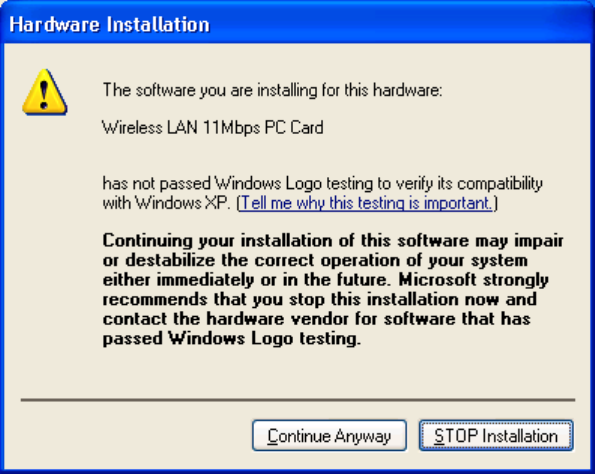
Once your system detected the driver, Microsoft will show a warning message as below.
Click “ Continue Anyway ” for next step.
Wireless LAN
User manual Wireless LAN 11 Mbps
9
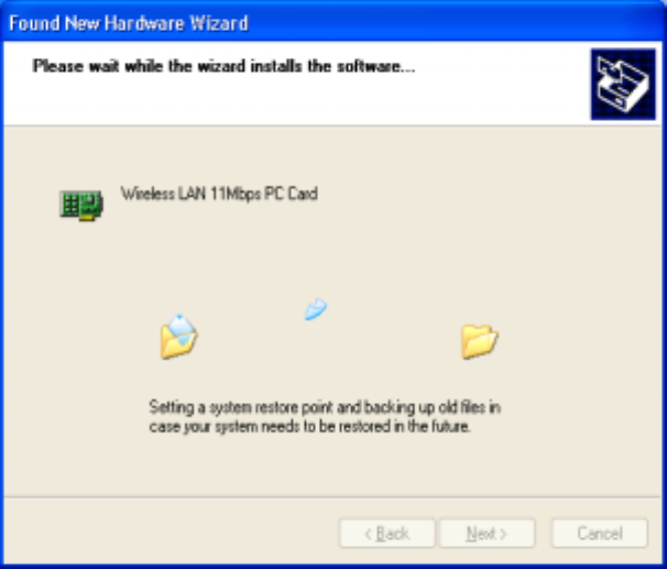
After copy the file to your system, then the setup is finish.
Wireless LAN
User manual Wireless LAN 11 Mbps
10
3.3. Install Procedure for Windows 98/ME/2000
Please follow the following steps one by one in order to install the WLAN Mini-
PCI successfully.
Note: Install WLAN CF card on your laptop PC must add additional PCMCIA Mini-PCI.
1. Power on your computer and allow Windows 98/ME/2000 to load fully.
2. Be sure that there is no Wireless LAN 11Mbps Mini-PCI inserted yet.
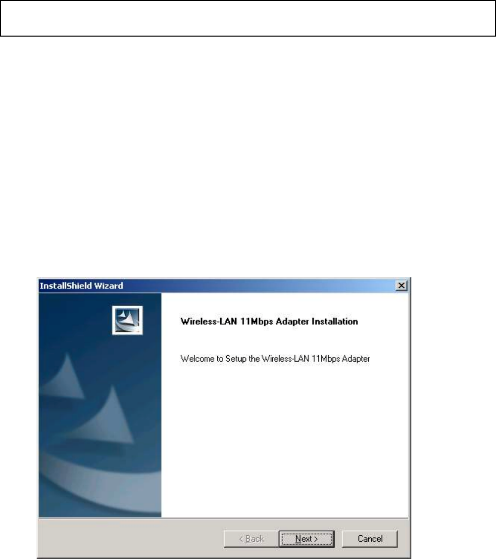
3. Insert the given Installation CD in the CD-ROM and then click on the Setup.
At the “ Welcome” window, click Next.
Note: Do not insert the WLAN Adapte
r
until you are asked to do so, failure of which may result in unsuccessful
installation of your WLAN device.
Wireless LAN
User manual Wireless LAN 11 Mbps
11
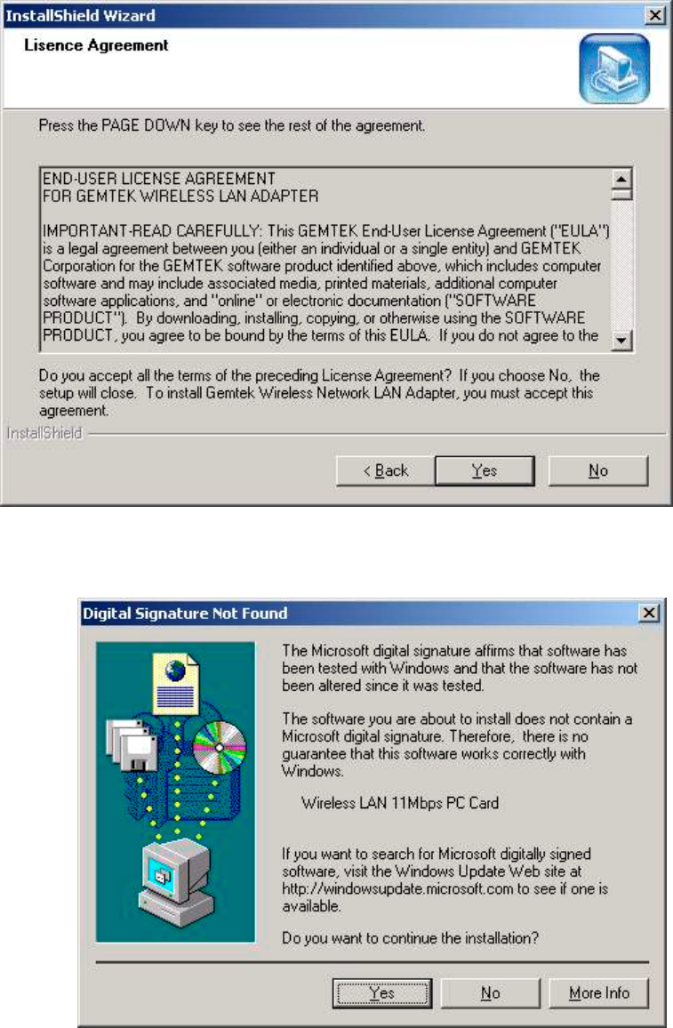
4. Accept the license agreement.
Accept the license agreement. Click Yes to accept.
Click Yes to finish the setup.
5. Insert / attach Wireless LAN 11 Mbps Mini-PCI to your system
Wireless LAN
User manual Wireless LAN 11 Mbps
12
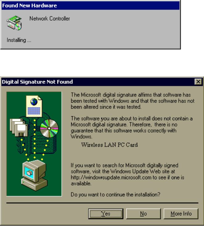
Windows will recognize the WLAN Mini-PCI and auto detect the driver, if the system did not find the
driver automatically, please install the driver manually.
.
Click Yes to finish the installation.
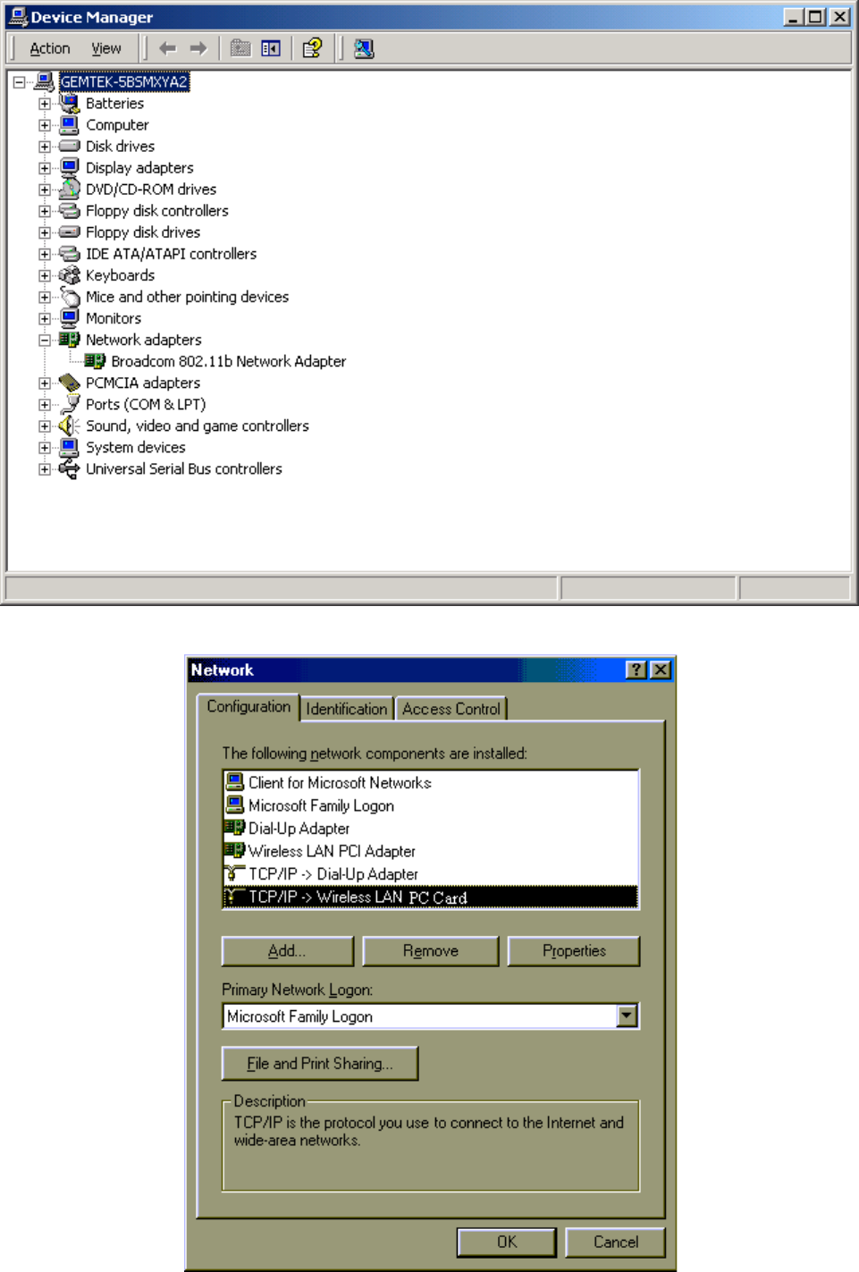
6. Click the right button of mouse on My Computer "
""
" Properties "
""
" Device Manager.
Check whether it has WLAN Mini-PCI in one of the sockets or not. If you find Wireless LAN
11Mbps Mini-PCI in one of the sockets, it means the card is detected properly.
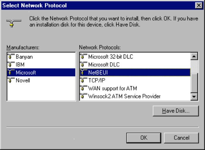
7. Click right button of mouse on the Network Neighborhood.
8. Select Properties from the pop up menu. The network box appears and you see three main tables:
Configuration, Identification, and Access Control.
Wireless LAN
User manual Wireless LAN 11 Mbps
13
9. Click on the Configuration tab and then click on the Add button. Select Network Component Type
box appears. Click on the Protocol the click the Add button.
Wireless LAN
User manual Wireless LAN 11 Mbps
14
10. Select Network Protocols box appears. From the list of manufactures, click on Microsoft. From the
list of network protocols list, select NetBEUI, then click OK.
11. The NetBEUI protocol is now installed. After clicking on OK return back to Network Component
Type box.
12. Repeat the step 15 and 16 to add IPX/SPX protocol.
13. Repeat the step 15 and 16 to add TCP/IP protocol.
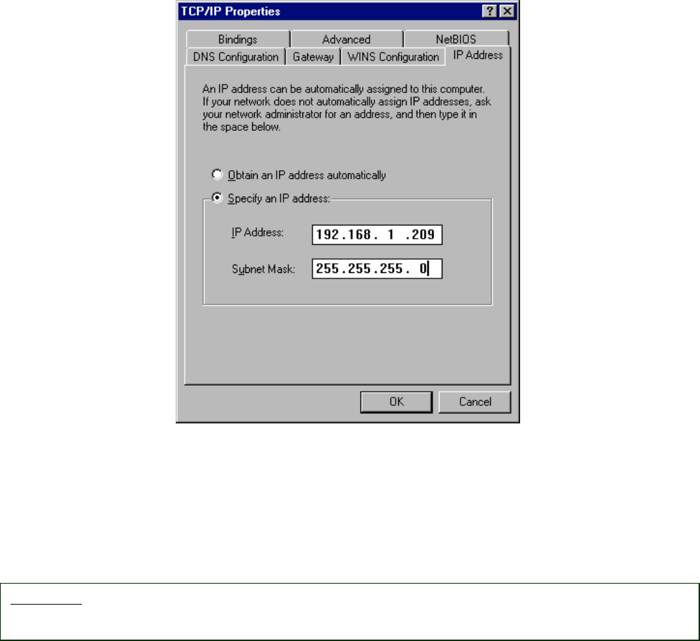
14. Click on the TCP/IP option for setting the IP address for your computer. You can select either Static
or DHCP setting. If you use the static IP setup then enter the IP value, Subnet masking, DNS,
Domain/ Workgroup name, and Gateway Address values. After setting these parameters
appropriately, click OK to return to Network Component Type and you can select the File and
Printer Sharing options as well as the Access to your computer like other users connected to that
network by setting the computer sharing options. Click on OK.
Wireless LAN
User manual Wireless LAN 11 Mbps
15
15. Screen message do want to restart your Computer will pop up. Select Yes. It will shut down your
computer and restart.
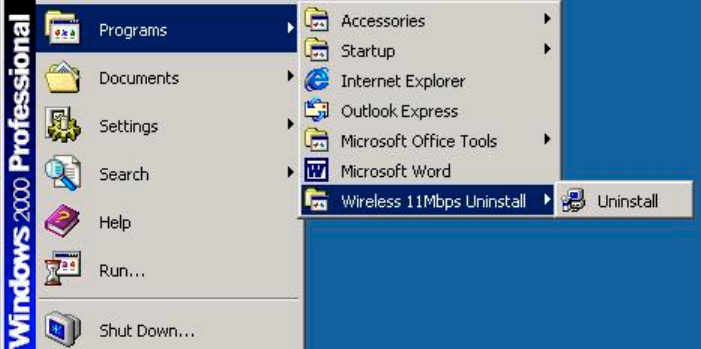
Uninstall Procedure
Step 1:
If you want to uninstall the WLAN Mini-PCI, just simply click
Start Menu " Program File " Wireless "
""
" Uninstalled, it shall uninstall all related programs.
Important: Restart your computer to make the changes effective before you reinstall the
driver.
Wireless LAN
User manual Wireless LAN 11 Mbps
16
Step 2:
Restart your Computer.
Wireless LAN
User manual Wireless LAN 11 Mbps
17
4. Configuration Utility
Wireless LAN 11 Mbps Wireless LAN Mini-PCI uses its own management software. All functions
controlled by user are provided by this application. Usually this application starts automatically,
or click icon from Start Menu to start the Utility application.
A new icon - should appear in your Icon tray. If the icon is in red, it means that Wireless LAN 11
Mbps NIC configuration is invalid or incomplete. Sometimes icon can be colored in red. This may
happen when communication is defined poor connection or incorrectly.
Figure 1 Icon tray with a new icon
User can navigate through “sheets”, by clicking tabs. “X” button will minimize window.
Below description explains the use and meanings of the various screen messages.
Wireless LAN
User manual Wireless LAN 11 Mbps
18
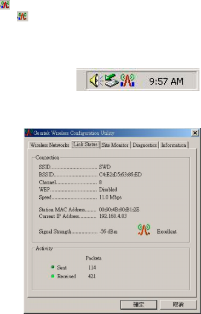
4.1 Link Status
- Status
This field is used to display the current status of connection. When the state shows “Connected to
SSID“ means normal flow of operation in Infrastructure mode. The PC is connected to access
point. Networking is available.
A state of “Scanning” means that the node is searching for available access point and unable
detects the SSID for an available access point within range.
This field will also display an error message for some reason if the driver failed to initialize.
Network Type
Infrastructure Mode - The driver will scan all available channels continuously until it finds one or
more Access Points that matches its SSID. At that point it will try and authenticate and
associate with the Access Point.
Ad Hoc Mode - The driver will scan for 5 seconds looking for an existing Ad Hoc network
using the same SSID.
- Current Channel and Transmit Rate
Shows the channel of the radio and transmit rate are being currently used for an active connection.
This value has no meaning when the radio is “Scanning”
- Link Quality
The Link Quality bar graph is only active when the node is in Infrastructure Mode. The bar graph
displays the quality of the link between the node and Access Point. It summarizes the quality of
the link over the bar graph, which can take on one of the following values:
“Poor”
“Fair”
“Good”
“Very Good”
“Excellent”
- Signal Strength
The Signal Strength bar graph is only active when the node is in Infrastructure Mode. The bar
graph displays normalized signal strength as reported by the radio, averaged over all frames over
100 bytes long that are received from the Access Point.
Wireless LAN
User manual Wireless LAN 11 Mbps
19
4.2 Connections
The Connections Tab shows current status of available APs within the network.
User may select profile or ESSID from above list, click “Connect” to connect with the AP.
Click “Refresh” to rescan the network, this utility with site survey function, it will detect and list all
available APs within network.
Place a check mark in the field if you wish attempt Auto-connect to ANY network in the range.
.
Wireless LAN
User manual Wireless LAN 11 Mbps
20
4.3 Profile Setting
Profile Setting allow user to create profiles for different network environments.
Click “New” button to create new profiles.
“Edit” for edit current exist profile.
Click “Delete” button if you wish to delete profiles.
Wireless LAN
User manual Wireless LAN 11 Mbps
21
- Network Type
This field allows you to select from a list of supported Network “Modes”. The modes displayed will
have two values: “Ad Hoc” and “Infrastructure”.
Ad Hoc - This is the 802.11 peer-to-peer mode of operation. In 802.11Ad Hoc only one wireless
“cell” is supported for each different SSID. All communication is done from Client to Client without
the use of an Access Point. 802.11 Ad Hoc networking uses the same SSID for establishing the
wireless connection.
Infrastructure - This mode of operation requires the presence of an 802.11 Access Point. All
communication is done via the Access Point, which relays packets to other wireless Clients in
the BSS as well as to nodes on a wired network such as Ethernet.
Transmit Rate – The transmission rate at which client of AP transmits the data packets. You may
set this to fixed 1Mbps, fixed 2 Mbps, fixed 5.5 Mbps or 11 Mbps.
Encryption (WEP) - You may desire an additional measure of security on your wireless network,
which can be achieved by using WEP (Wired Equivalent Privacy) encryption.
When an encrypted frame is received it will only be accepted if it decrypts correctly. This will only
happen if the receiver has the WEP Key used by the transmitter.
This panel allows to entry for 64/128-bit encryption according to WEP function select. To be
written to the driver and registry, such as Hexadecimal format, each key must consist of hex digits,
which means that only digit 0-9 and letters A-F are valid entries. If entered incorrectly program will
not write keys to a driver.
Wireless LAN
User manual Wireless LAN 11 Mbps
22
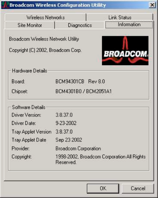
4.4 About
About tab shows the product version including the detail of Driver, Application and firmware version.
Users must use this version number when reporting their problems to technical support.
Wireless LAN
User manual Wireless LAN 11 Mbps
23
Wireless LAN
User manual Wireless LAN 11 Mbps
24
4.5 Windows XP Zero Configuration
Microsoft provides Windows XP Zero Configuration, which means user doesn’t need to use software
provided by the manufacturer. Instead, Windows XP recognizes the Mini-PCI and provides the
necessary driver and configuration software.
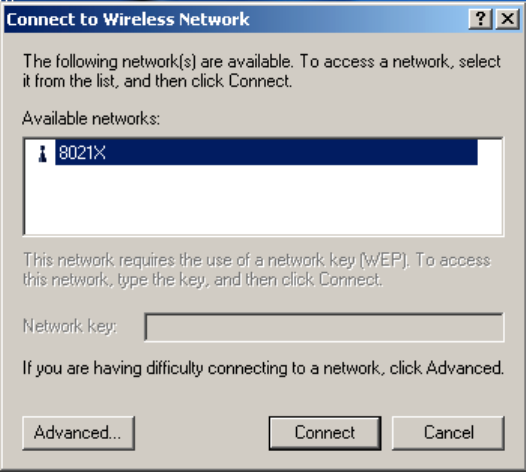
If your station is within range of a WLAN, Windows XP announces that one or more wireless networks
are available and suggests that you click the Network icon to see a list of available networks.
Configuring Automatic Network Connections
To configure one or more wireless networks for auto connection, follow these steps:
1. Right-click a Network icon in the notification area at the bottom of the screen to display a pop-up
menu. Click the Open Network Connections option.
2. Right-click the Wireless Network Connection icon and click Properties in the Pop-up menu.
Windows XP displays the Wireless Network Connection Properties dialog.
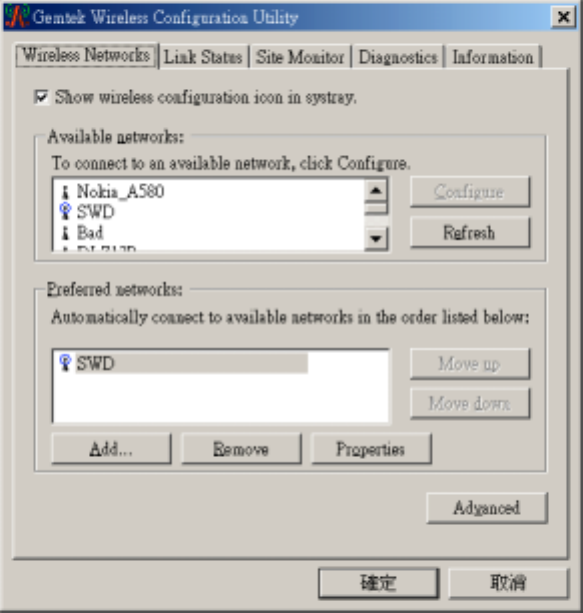
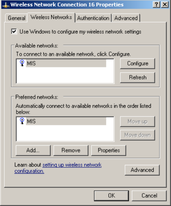
3. Click the Wireless Networks tab, shown as below. Notice that the wireless network that was present
when you first inserted the wireless NIC is already listed.
Wireless LAN
User manual Wireless LAN 11 Mbps
25
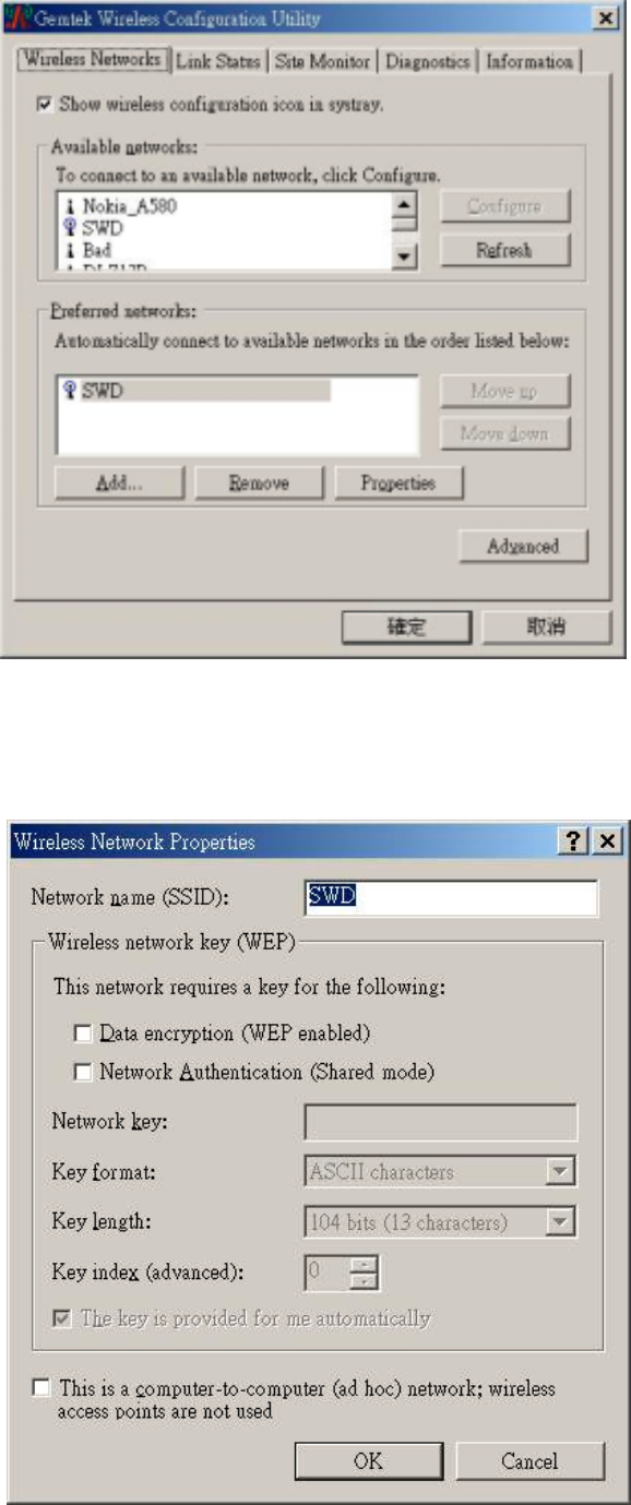
4. To add another network to the list, click the Add button on the Wireless Networks tab to display the
Wireless Network Properties dialog.
5. Type a network name ( SSID) in the Network name test box.
6. If you have implemented a system automatically providing users with network keys and /or WEP
keys, click OK to save this network SSID and move on to the next network that you want to configure.
7. If you are setting up an ad hoc mode wireless connection, click the last check box in the dialog.
Otherwise, if you are configuring a connection to an AP, leave the check box uncheck and click OK.
Windows XP adds the network to the list of preferred networks in the Wireless Network Connection
Properties dialog box.
8. When you finish adding all wireless networks to which you expect this computer to need access,
click OK.
Note: XP includes support for IEEE 802.1X standard for port –level authentication of stations in the
network.

Wireless LAN
User manual Wireless LAN 11 Mbps
26
5. Troubleshooting
If you encounter any problems during the installation, or to confirm that the WLAN 11Mbps device is
installed properly, please read the following troubleshooting section.
In Windows 98:
To check that the WLAN 11Mbps device is installed properly, please do the following:
1.
Go to START>SETTINGS>CONTROL PANEL>NETWORK. Choose the Configuration Tab. If you
find the WLAN 11Mbps Mini-PCI, it means the card is installed properly. If you see the Yellow
Question-mark (?) means the resources are conflicting. (Please read further in this section for
solutions.) -or-
2.
Right click on My Computer and select Properties. Select the Device Manager and click on the
Network Mini-PCI. You will find the WLAN 11Mbps Mini-PCI if it is installed successfully. If you see the
Yellow sign, the resources are
conflicting. Click on the PCMCIA Card and then on the PCMCIA Card
Service, you can see the
status of the PC card. If there is a yellow sign either on the Mini-PCI or the PC
card, please check the following.
1. Check to see if your computer supports 3.3V Card.
2. Check to see if your computer has a free IRQ. If not, make an IRQ free by assigning the
same IRQ to some devices, for example COM 1; COM 2 can be assigned the same IRQ
values.
3. Check that you have inserted the right card and have installed the proper driver.
In Windows 2000:
1. Check the Windows 2000 Diagnostics. See if there is any conflict in the resource allocation or
the I/O Address, IRQ allocations. If you find that the IRQ or I/O Addresses are already assigned
to some other devices, you must change that value. I/O Address needs 40h byte length.
2. Go to the Control panel. Double click on the PCMCIA Card and you will see WLAN Mini-PCI.
Double clicking on that will show you the Card Information, driver name and the driver file. You
must confirm the name of the driver and the driver file as "prismnic.inf" and "prismnds.sys". If
you do not find the names listed above, there are some problems and the driver is not installed
properly. Reinstall the driver.
Note: Check the PnP BIOS setup menu and select no in case of the WLAN Mini-PCI installation.
Wireless LAN
User manual Wireless LAN 11 Mbps
27
6. Technical specifications of Wireless LAN
Driver support
- Windows XP
− Windows 98
− Windows 2000
− Windows ME
- Win CE (Strong ARM platform)
Standards supported
− IEEE 802.11 standard for Wireless LAN
− All major networking standards (including TCP/IP, IPX)
Environmental
Operating temperature (ambient):
− -10°C to 50°C (Operating),-20 to 70°C (Storing)
− Max. Humidity: 95% Non-condensing
Power specifications
− Transmit Power, 2.7v to 3v: 15 dBm min.
Radio specifications
Range:
− per cell indoors approx. 35-100 meters or more
− per cell outdoors up to 100-300 meters
Frequency range:
− 2.4-2.4835 GHz, direct sequence spread spectrum
Number of Channels:
− Europe: 13 (1-13 )
− US: 11 (1-11 )
− France: 4 (10-13 )
− Japan: 14 (1-14 )
Antenna system:
− Internal patch antenna supporting diversity.
Mobility:
− Seamless roaming across cell boundaries with handover
Wireless LAN
User manual Wireless LAN 11 Mbps
28
Specific features
Supported bit rates:
− 11 Mbps
− 5.5 Mbps
− 2 Mbps
− 1 Mbps
Data encryption:
− 64 /128 bit WEP Encryption
Utility Software:
− Management utility software
Wireless LAN
User manual Wireless LAN 11 Mbps
29
Federal Communication Commission Interference Statement
This equipment has been tested and found to comply with the limits for a Class B digital device,
pursuant to Part 15 of the FCC Rules. These limits are designed to provide reasonable
protection against harmful interference in a residential installation. This equipment generates,
uses and can radiate radio frequency energy and, if not installed and used in accordance with
the instructions, may cause harmful interference to radio communications. However, there is
no guarantee that interference will not occur in a particular installation. If this equipment does
cause harmful interference to radio or television reception, which can be determined by turning
the equipment off and on, the user is encouraged to try to correct the interference by one of the
following measures:
- Reorient or relocate the receiving antenna.
- Increase the separation between the equipment and receiver.
- Connect the equipment into an outlet on a circuit different from that
to which the receiver is connected.
- Consult the dealer or an experienced radio/TV technician for help.
FCC Caution: To assure continued compliance, (example - use only shielded interface cables
when connecting to computer or peripheral devices). Any changes or modifications not
expressly approved by the party responsible for compliance could void the user's authority to
operate this equipment.
This device complies with Part 15 of the FCC Rules. Operation is subject to the
following two conditions: (1) This device may not cause harmful interference, and (2) this
device must accept any interference received, including interference that may cause
undesired operation.
IMPORTANT NOTE:
FCC Radiation Exposure Statement:
This equipment complies with FCC radiation exposure limits set forth for an uncontrolled
environment. End-users must follow the specific operating instructions for satisfying RF
exposure compliance.
This transmitter must not be co-located or operating in conjunction with any other antenna or
transmitter.

This device is intended only for OEM integrators under the following conditions:
1) The antenna must be installed such that 20 cm is maintained between the antenna and users. For laptop
installations, the antenna must be installed to ensure that the proper spacing is maintained in the event the users
places the device in their lap during use (i.e. positioning of antennas must be placed in the upper portion of the
LCD panel only to ensure 20 cm will be maintained if the user places the device in their lap for use) and
2) The transmitter module may not be co-located with any other transmitter or antenna.
As long as the 2 conditions above are met, further transmitter testing will not be required. However, the OEM
integrator is still responsible for testing their end-product for any additional compliance requirements required
with this module installed (for example, digital device emissions, PC peripheral requirements, etc.).
IMPORTANT NOTE: In the event that these conditions can not be met (for example certain laptop
configurations or co-location with another transmitter), then the FCC authorization is no longer considered
valid and the FCC ID can not be used on the final product. In these circumstances, the OEM integrator will be
responsible for re-evaluating the end product (including the transmitter) and obtaining a separate FCC
authorization.
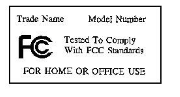
End Product Labeling
This transmitter module is authorized only for use in devices where the antenna may be installed such that 20
cm may be maintained between the antenna and users (for example access points, routers, wireless ASDL
modems, certain laptop configurations, and similar equipment). The final end product must be labeled in a
visible area with the following: "Contains TX FCC ID: MXF-M911031B".
RF Exposure Manual Information That Must be Included
The users manual for end users must include the following information in a prominent location "IMPORTANT
NOTE: To comply with FCC RF exposure compliance requirements, the antenna used for this transmitter must
be installed to provide a separation distance of at least 20 cm from all persons and must not be co-located or
operating in conjunction with any other antenna or transmitter."
Additional Information That Must be Provided to OEM Integrators
The end user should NOT be provided any instructions on how to remove or install the device.
Wireless LAN
User manual Wireless LAN 11 Mbps
31
R&TTE Compliance Statement
This equipment complies with all the requirements of the DIRECTIVE 1999/5/EC OF THE
EUROPEAN PARLIAMENT AND THE COUNCIL of 9 March 1999 on radio equipment and
telecommunication terminal Equipment and the mutual recognition of their conformity (R&TTE).
The R&TTE Directive repeals and replaces in the directive 98/13/EEC (Telecommunications Terminal
Equipment and Satellite Earth Station Equipment) As of April 8, 2000 .
Safety
This equipment is designed with the utmost care for the safety of those who install and use it. However,
special attention must be paid to the dangers of electric shock and static electricity when working with
electrical equipment. All guidelines of this manual and of the computer manufacturer must therefore be
allowed at all times to ensure the safe use of the equipment.
EU Countries intended for use
The ETSI version of this device is intended for home and office use in Austria, Belgium, Denmark,
Finland, France (with Frequency channel restrictions), Germany, Greece, Ireland, Italy, Luxembourg,
The Netherlands, Portugal, Spain, Sweden and United Kingdom.
The ETSI version of this device is also authorized for use in EFTA member states Iceland,
Liechtenstein, Norway and Switzerland.
EU Countries Not intended for use
None.
Potential restrictive use
France: Only channels 10,11,12, and13