GemTek Technology M921015AG Wireless 11a+g mini-PCI User Manual
Gemtek Technology Co., Ltd. Wireless 11a+g mini-PCI Users Manual
UserManual.wiki
>
GemTek Technology
>
M921015AG User Manual
>
Users Manual
Contents
1.
DoC
2.
Users Manual
Users Manual
Navigation menu
Upload a User Manual
Namespaces
Wiki Guide
HTML
PDF
Info
Views
User Manual
Discussion / Help
Navigation

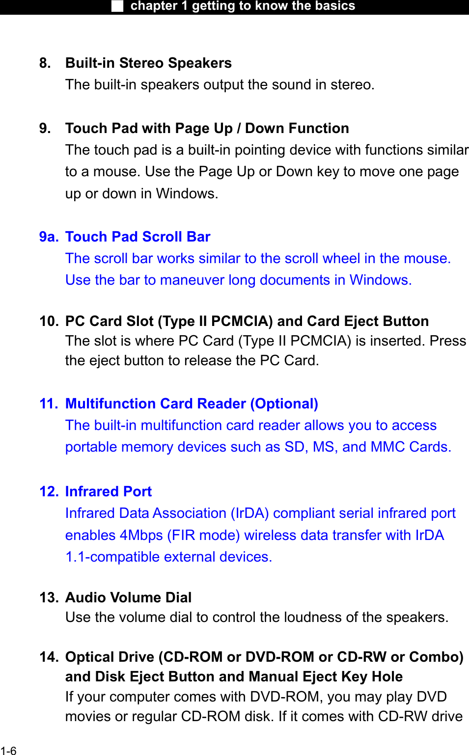
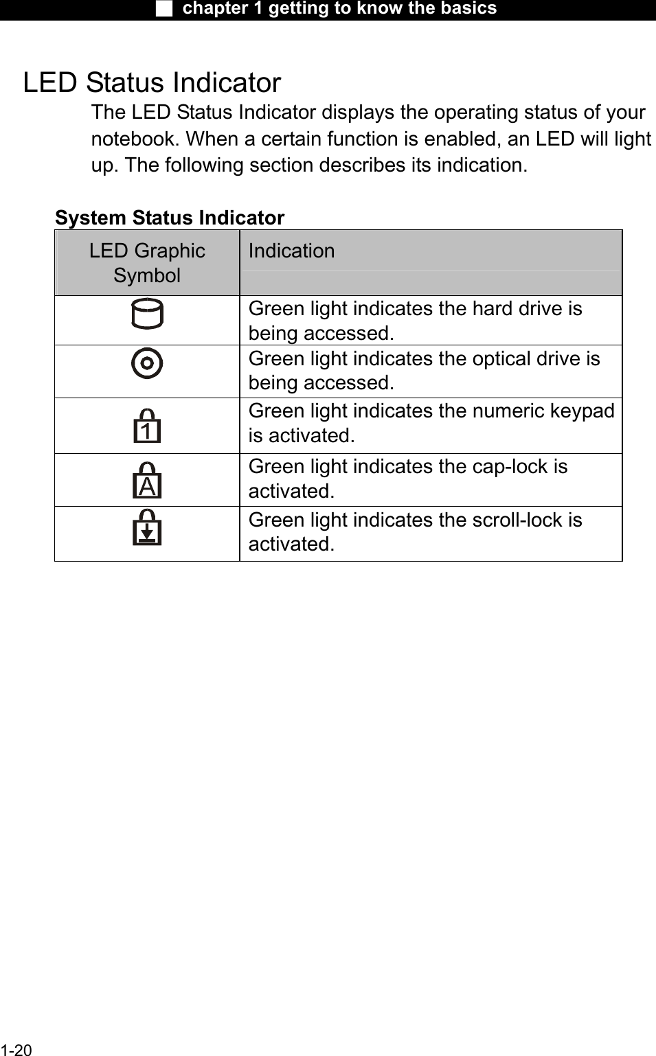
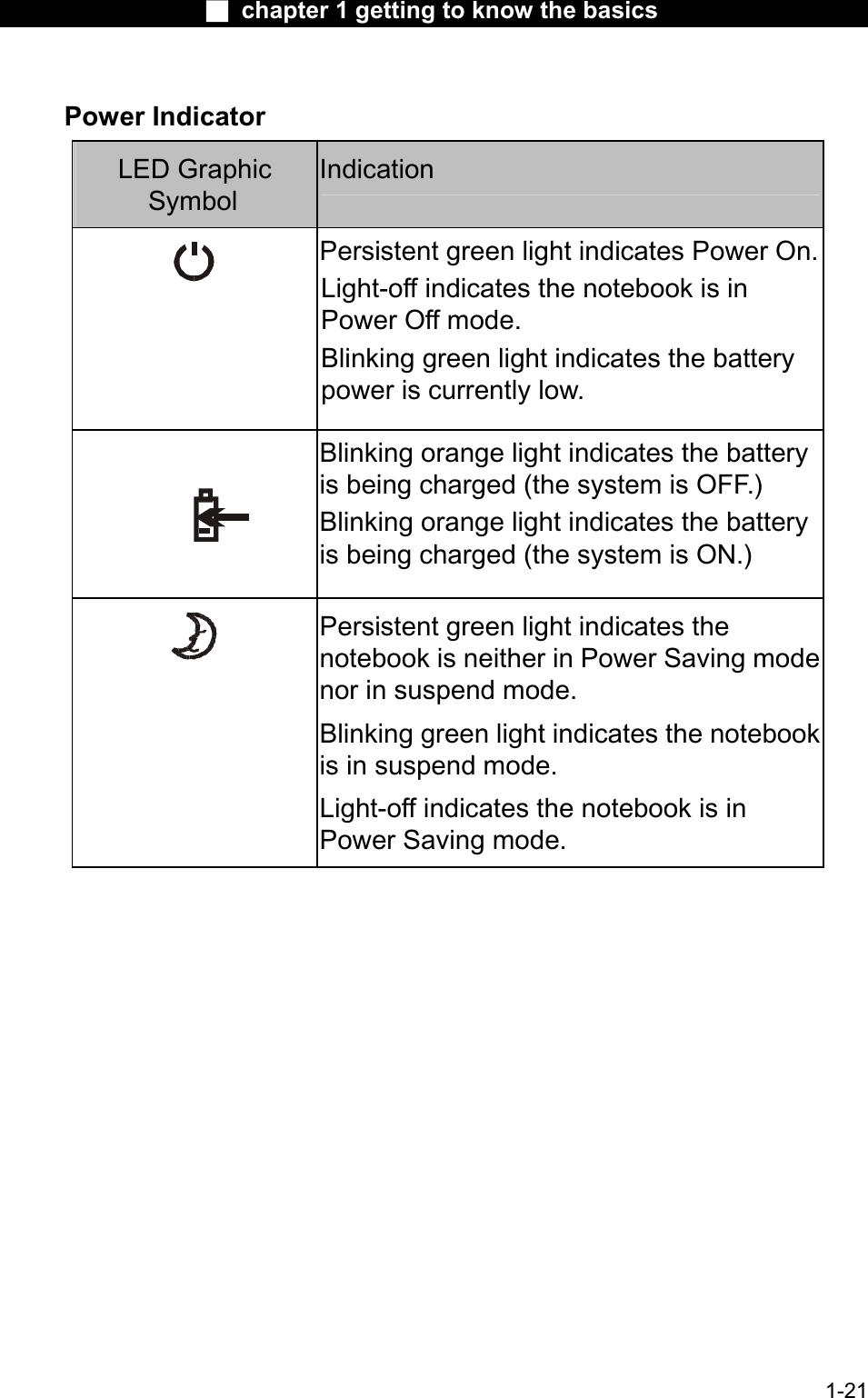
![Ϯ chapter 1 getting to know the basicsor Combo drive, you may save data onto a CD-R / CD-RW disk.Press the eject button to eject the disk tray. The manual eject keyhole allows you to manually eject a jammed disk.Note: The optical drive resides in the Swappable Device Bay. Additionally,you may also purchase an optional hard drive module to be used in this bay.15. TV (S-Video) Port The S-Video port permits you to redirect the screen output to a television set or any analog video playback device. This TVPort is Macrovision-compliant; when DVD movie is played, the output is scrambled to prevent analog recording.16. LED Status IndicatorThe LED Status indicators reveal the locking/unlocking of certain key functions - numeric keypad enable/disable, cap lock, and scroll lock - and HDD and optical drive status. (See the LED Status Indicator Section for details.)17. Power / Suspend ButtonThe power/suspend button turns the notebook on and off and it also acts as a system suspend key. Press momentarily to turn on the system. Press and hold for at least 3~4 seconds to turn off the system. How this key behaves can be defined in [Start > Settings > Control Panel > Power Options > Advanced] menu. Press the power / suspend button again to return from the suspend mode. (See Chapter 3 for more details on systemsuspend function.)18. Internet Quick KeyThe Internet Quick Key launches the Internet Explore 1-7](https://usermanual.wiki/GemTek-Technology/M921015AG.Users-Manual/User-Guide-388274-Page-7.png)
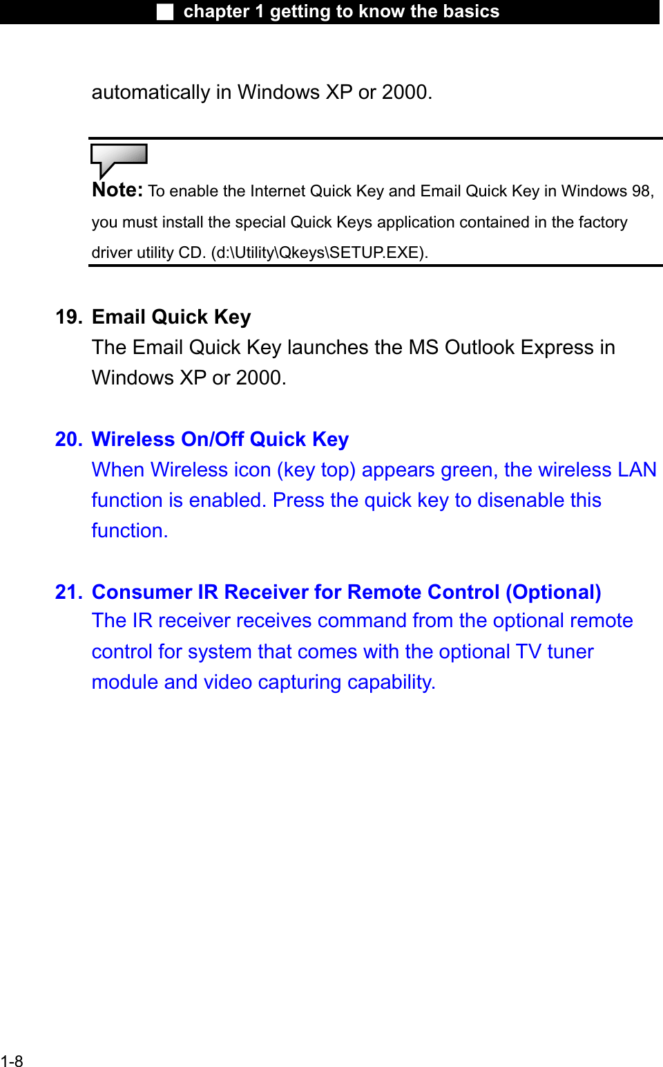
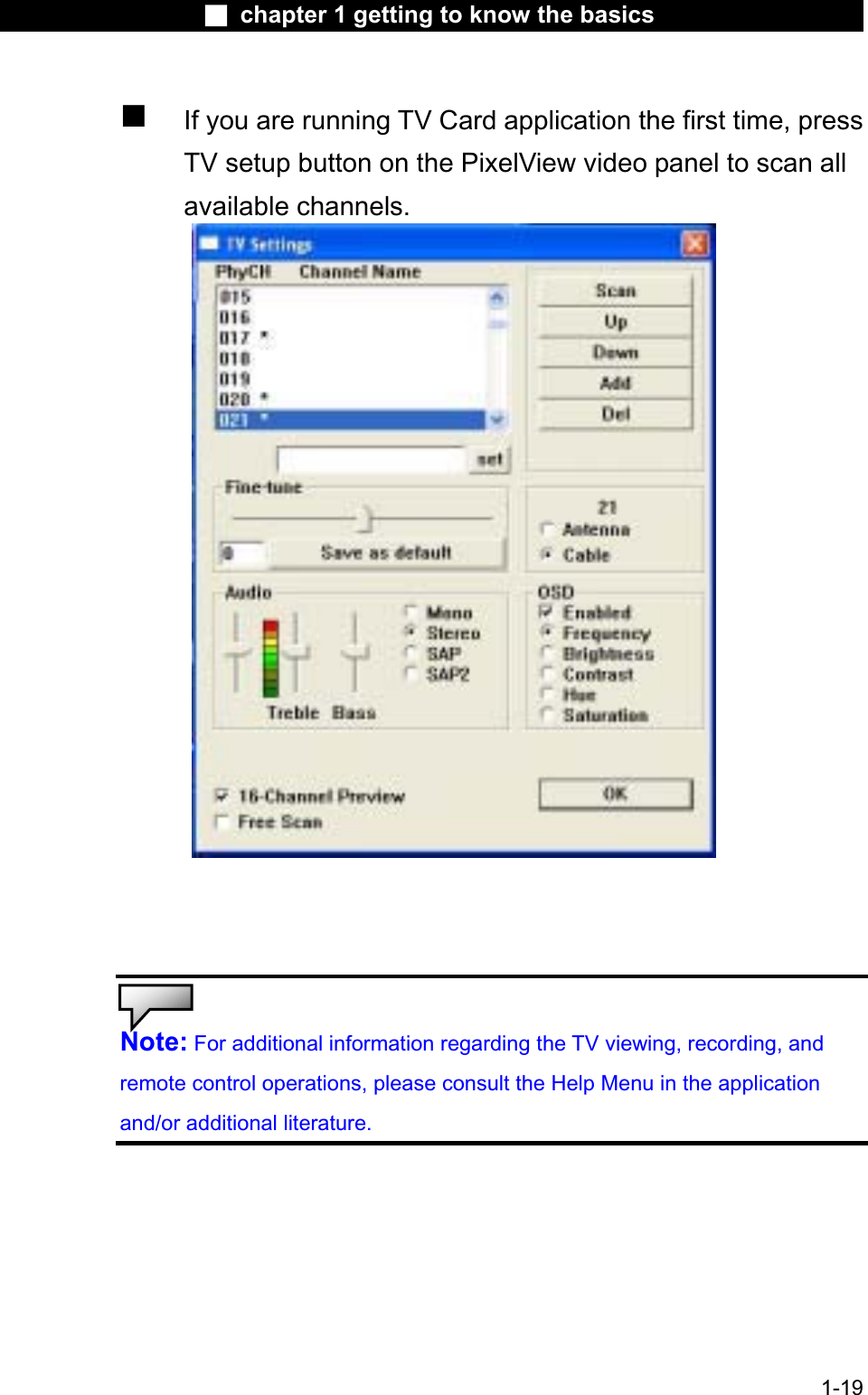
![Ϯ chapter 1 getting to know the basicsYou may need to make sure that the TV Card is set to the correct region for it to tune-in accurately. Go to [Start > Programs > TV Card > SW Configuration]. See below.Press TV button on the remote and the PixelView TVCard application will start. Or, simply go to [Start > Programs > TV Card > TV Card] to launch the application.See below.1-18](https://usermanual.wiki/GemTek-Technology/M921015AG.Users-Manual/User-Guide-388274-Page-18.png)
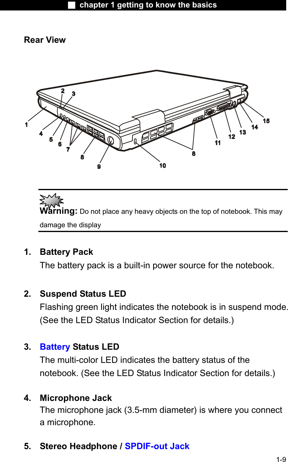
![Ϯ chapter 1 getting to know the basicsModemYour computer comes with a 56K V.90 internal fax/modem and a phonejack (RJ-11), which is located on the right rear side of your computer.Use a telephone cable to connect the computer to the telephone wall outlet.Connecting the Modem1. Plug one end of the phone line into the modem port located on the rear side of the computer. (For EMI compliance, you need to clipthe included EMI CORE to the phone line.) 2. Plug the other end of the line into the analog phone wall outlet.Depending on where your computer is used, you may need to changesettings in the modem. Correct setting will allow you to maintain a stableconnection in a country where its telecommunication system may be different to others.To change the modem setting, do the following:1. Go to [Start > Settings > Control Panel] and double-click onModem Settings icon. You will see a similar dialog box. 2. Click on the pull-down menu and select the country where it is applicable. Click on OK to exit. 1-28](https://usermanual.wiki/GemTek-Technology/M921015AG.Users-Manual/User-Guide-388274-Page-28.png)
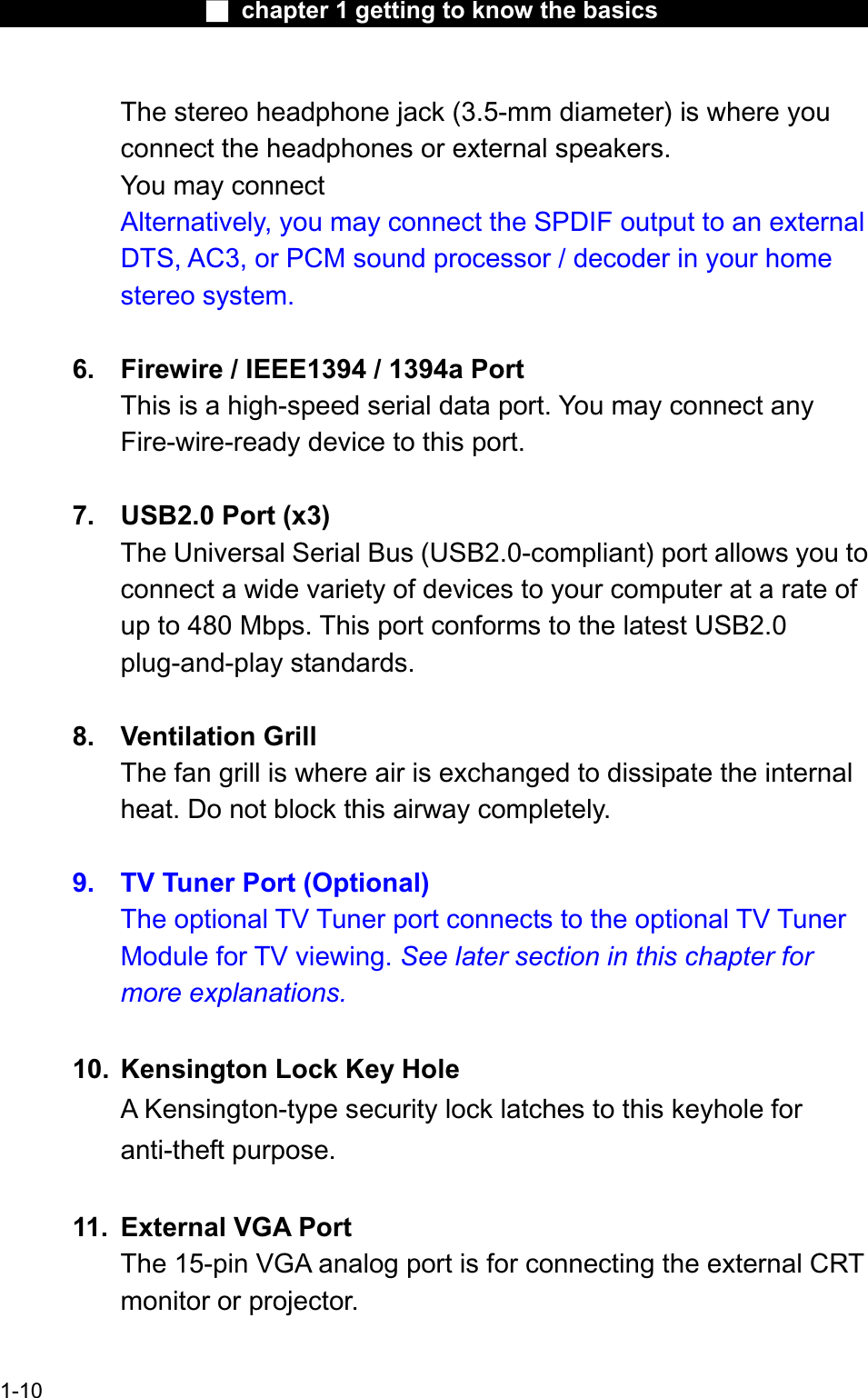
![Ϯ chapter 1 getting to know the basicsEthernetYour computer is equipped with a 10/100Base-TX Fast Ethernet network adapter. Connect the active LAN cable to the RJ-45 LANport located on the left rear side of the computer. This allows you to access and transmit data in the local area network. Connecting to the NetworkUse Unshielded Twisted Pair (UTP) Ethernet cable only.1. Insert one end of the UTP cable into the network connectoruntil the connector snaps securely into the receptacle.2. Either connect the other end of the cable to an RJ-45 jackwall outlet or to an RJ-45 port on a UTP concentrator or hub in the network.Cabling Restriction for NetworksThe following restrictions should be observed for 100BASE-TX networks:The maximum cable run length is 100 meters(m) (328feet[ft]).For 100-Mbps operations, use Category 5 wiring andconnections.Note: Consult Windows manual and / or Novell Netware user’s guide for the software installation, configuration, operation of the network.1-29](https://usermanual.wiki/GemTek-Technology/M921015AG.Users-Manual/User-Guide-388274-Page-29.png)
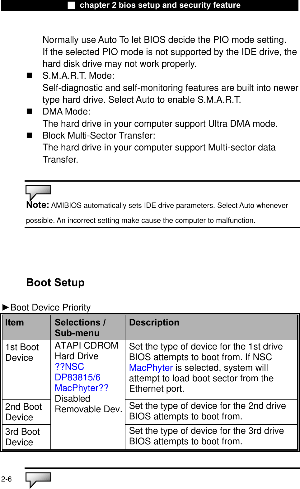
![Ϯ chapter 2 bios setup and security featurePrimaryIDEMasterPrimary Master is where BIOS tries to boot from first. The primary master controls the hard drive. Normally, Autois selected.SecondaryIDEMasterAutoARMDATAPI CDROMNot InstalledThe secondary master controls the ATAPI CD-ROM drive. Normally, Auto isselected.ŹSuper IO Configuration (Port Address)Item Selections /Sub-menuDescriptionIR Mode SIRFIR Choose Fast IR for greater databandwidth.On Board ParallelPortDisabled378 / IRQ7 278 / IRQ5 [Disabled]:The port is disabled.Or you may choose a value for the parallel port. ParallelPort Mode NormalECP+EPPEPPECPYou may choose any one of these settings. ECP offers the bestperformance.About Hard Disk Drive Setting Select Auto to let BIOS configure the drive parametersautomatically. Only for certain old types of hard disk drive will you need to modify the settings. After pressing Enter on [Hard Disk],BIOS display the drive parameters. If the detected drive parametersare not correct or if you’re trying to enable the enhanced IDE feature, you may still change the value manually.32 Bit Mode: Select On to allow data transmission in 32-bit format. PIO Mode:2-5](https://usermanual.wiki/GemTek-Technology/M921015AG.Users-Manual/User-Guide-388274-Page-34.png)
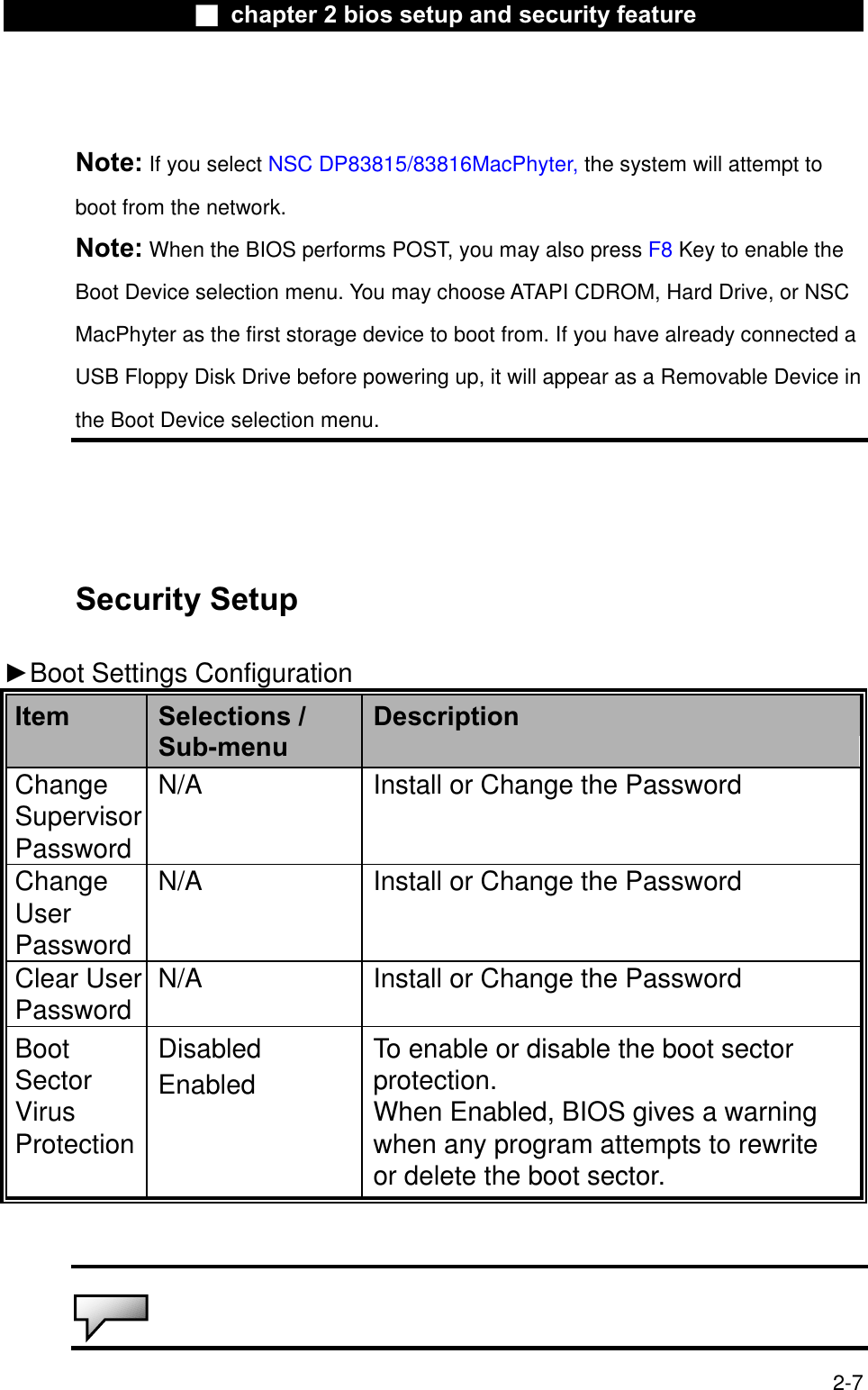
![Ϯ chapter 2 bios setup and security featureNote: About Boot Sector Virus Protection: If enabled, the following warning message appears when a program attempts to alterthe boot sector. You may have to enter “N” several times to prevent the boot sector write.Boot Sector Write!!!Possible VIRUS: Continue (Y/N)? _The following warning message appears when a program attempts to format thehard disk drive. Format!!!Possible VIRUS: Continue (Y/N)? _Using Password Protection Two Levels of Password Protection are available. The BIOSprovides both a Supervisor and a User password. If you try to activate both passwords, the Supervisor password must be set first.The passwords activate two different levels of protection:1. System always asks for password every time it is powered on. 2. System asks for password only when you attempt to enter BIOS utility.The passwords are encrypted and stored in NVRAM. Make sureyou write them down or memorize them. If you lost the passwords,the computer may need to be sent back to the factory or to an authorized service dealer to reset the passwords.Power Setup Item Selections /Sub-menuDescriptionPower Button Mode On/OffSuspend[On/Off]: When the power button is pressed, the system is turned off.[Suspend]: When the power button is pressed, the system enters the suspendmode. !2-8](https://usermanual.wiki/GemTek-Technology/M921015AG.Users-Manual/User-Guide-388274-Page-37.png)
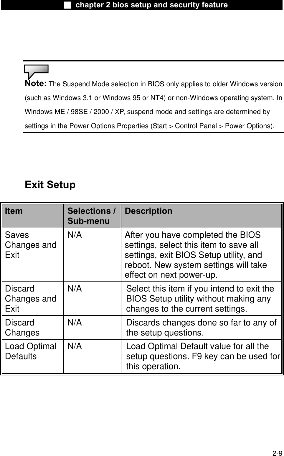

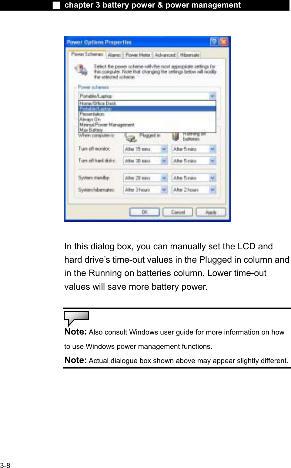
![Ϯ chapter 3 battery power & power managementUsing Windows Power OptionsWindows Power Management provides basic power saving features. In the Windows Power Options Properties [Start > Settings > Control Panel > Power Options] dialogue box, you may enter time-out values for display and hard disk drive. Windows power manager saves power by turning off hard driveafter 1 minute of inactivity, for example.Windows’ Power Schemes The power management control panel in Windows XP, known as Power Schemes, is designed to provide theuser with an easy-to-use interface. The Power Schemestab can be found in the Power Options Properties panelthat is accessible via the control panel window.Schemes are easy to understand, based on notebookusage scenarios, and control not only processor powerusage but other system peripherals as well. Go to [Start > Settings > Control Panel] and double-clickthe Power Options icon. Always on mode puts the processor into maximum performance mode, which provides no power saving.The other schemes control processor performancebased on demand. For example, Max Battery mode lowers the processor’s speed and voltage to conservepower as much as possible.3-7](https://usermanual.wiki/GemTek-Technology/M921015AG.Users-Manual/User-Guide-388274-Page-45.png)
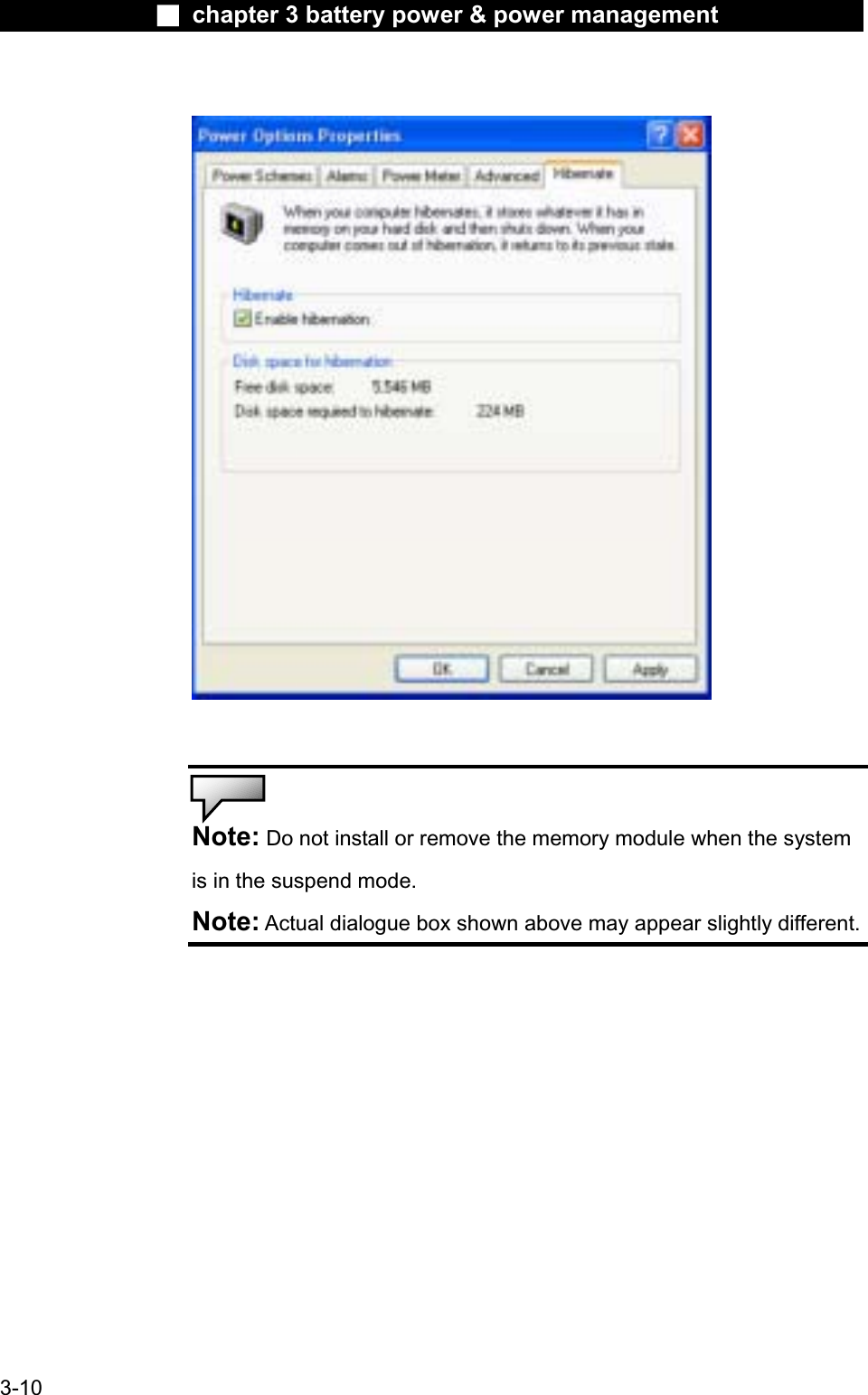
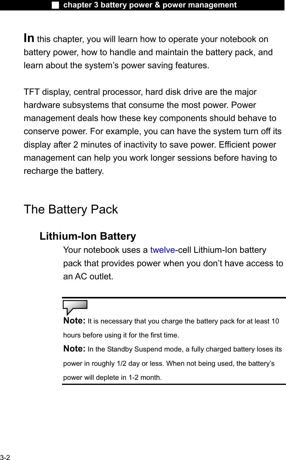
![Ϯ chapter 3 battery power & power managementPower Button ActionThe notebook PC’s power button can be set to turn offthe system or activate the suspend mode.Go to [Start > Settings > Control Panel > Power Options]and click on the Advanced tab. In the pull-down menu,select how you wish the power button to work as.Note: Actual dialogue box shown above may appear slightly different.Warning: In the When I close the lid of my portable computerpull-down menu, DO NOT select Do nothing – otherwise the system willstill run at high speed while the processor’s fan grill is fully blocked bythe closed LCD panel. The heat will damage the LCD panel.3-11](https://usermanual.wiki/GemTek-Technology/M921015AG.Users-Manual/User-Guide-388274-Page-49.png)

![Ϯ chapter 5 trouble shootingAudio Problems No speaker output - Turn up the volume dial located at the right edge of thecomputer. See Chapter 1 for its location. Software volume control is turned down in MicrosoftSound System or is muted. Double-click the speaker icon onthe lower right corner of the taskbar to see if the speaker hasbeen muted or turned down all the way. Most audio problems are software-related. If yourcomputer worked before, chances are software may have beenset incorrectly. Go to [Start > Settings > Control Panel] and double-clickthe Sounds and Audio Devices icon. In the Audio page, make sure that C-Media Wave Device is the default playback device.Sound cannot be recorded - Double-click the speaker icon on the lower right corner of the taskbar to see if the microphone has been muted.1. Click Options and select Properties.2. Select Recording and click the OK button. 3. After Click OK button, the recording volume control panelwill appear. Go to [Start > Settings > Control Panel] and double-clickthe Multimedia icon (or Sounds and Audio Devices icon). In the Volume or Audio page, make sure that C-Media Wave Device is the default recording device.5-4](https://usermanual.wiki/GemTek-Technology/M921015AG.Users-Manual/User-Guide-388274-Page-66.png)
![Ϯ chapter 5 trouble shootingHard Disk Problems The hard disk drive does not work or is not recognizable - If you had just performed a hard disk upgrade, make surethe hard drive connector is not loose and the hard disk drive is also correctly seated. Remove it and reinsert it firmly, and restart your PC. (Refer to Chapter 4 for details.) The new HDD may need to be partitioned and reformatted. O/S and drivers will need to be re-installed as well. Check the hard disk indicator LED. When you access afile, the LED lamp should light up momentarily. The new HDD may be defective or is not compatible. If your computer has been subjected to static electricityor physical shock, you may have damaged the disk drive. The hard drive is making abnormal whining noises - You should back up your files as soon as possible. Make sure the source of noise is indeed from the hard drive and not the fan or other devices. The hard disk drive has reached its capacity - Run Disk Cleanup utility in Windows. [Start > AllPrograms > Accessories > System Tools > Disk Cleanup] Thesystem will prompt you for what to do. Archive files or programs that you had no longer used by moving them to an alternative storage medium (floppy disk, optical record-able disk, etc.) or uninstall programs that no longer use. 5-5 Many browsers store files in the hard drive as a cache to speed up the performance. Check the program’s Online Help](https://usermanual.wiki/GemTek-Technology/M921015AG.Users-Manual/User-Guide-388274-Page-67.png)
![Ϯ chapter 5 trouble shootingfor instructions on decreasing the cache size or on removingtemporary Internet files. Empty the Recycle Bin to create more disk space. Whenyou delete files, Windows saves them to the Recycle Bin. The hard disk takes longer to read a file - If you have been using the drive for a period, the files may be fragmented. Go to [Start > Programs > Accessories >System Tools > Disk Defragmenter] to perform a disk defragmentation. This operation may take a while. Interrupt requests or problems with other hardwaredevices may have occupied the CPU and therefore slows downthe system performance.The files are corrupted - Run the Error-checking utility in Windows to check the HDD. Double-click My Computer. Right-click C: and selectProperties. Click Check Now in Error-checking in Tools.5-6](https://usermanual.wiki/GemTek-Technology/M921015AG.Users-Manual/User-Guide-388274-Page-68.png)
![Ϯ chapter 5 trouble shootingDisplay ProblemsThe display panel is blank when the system is turned on - Make sure the computer is not in the Standby or Hibernate suspend modes. The display is turned off to conserve energy in these modes.The screen is difficult to read - The display resolution should at least be set to at least1024x768 for optimal viewing.1. Go to [Start > Settings > Control Panel] and double-clickthe Display icon. 2. Under the Settings page, set screen resolution to at least 1024x768 and choose at least 256 colors.The screen flickers - It is normal if the display flickers a few times during shutting down or powering up. 5-8](https://usermanual.wiki/GemTek-Technology/M921015AG.Users-Manual/User-Guide-388274-Page-70.png)
![Ϯ chapter 5 trouble shootingKeyboard and Mouse Problems The built-in touch pad performs erratically - Make sure there is no excess perspiration or humidity on your hand when using the touch pad. Keep the surface of the touch pad clean and dry. Do not rest your palm or wrist on the surface of the touch pad while typing or using the touch pad.The built-in keyboard accepts no input - If you are connecting an external keyboard to the system,the built-in keyboard may not work. Try restarting the system. The characters on the screen repeat while I type. You may be holding the keys down too long while you’retyping. Keep the keyboard clean. Dust and dirt under the keyscould cause them to stick. Configure the keyboard to wait longer before the autorepeat feature starts. To adjust this feature, Go to [Start > Settings > Control Panel], and double-click the Keyboard icon. A dialogue box shows up with the adjustable settings for the keyboard.5-9](https://usermanual.wiki/GemTek-Technology/M921015AG.Users-Manual/User-Guide-388274-Page-71.png)
![Ϯ chapter 5 trouble shootingModem Problems The built-in modem does not respond - Make sure the modem driver is loaded properly. Go to [Start > Settings > Control Panel > Phone andModem Options] and go to Modems tab. Make sure SmartLink56K Voice Modem or Uniwill V.90 Modem is listed. Otherwise,click the Add button to add the modem drive, which is located in the factory CD-ROM (or floppy diskette). Go to [Start > Settings > Control Panel > System] and click Device Manager button in the Hardware page to check for possible resource or driver conflict. See Windows on-line help or manual for how to handle such problems. Make sure the phone line, which the computer isconnected to, is working.Connection difficulties - Be sure to disable Call Waiting on the phone line. Be sure to have the correct country setting where yourcomputer is used. [Start > Settings > Control Panel > Modem Settings > Configuration] In the Country/Area pull-down menu, select the appropriate country setting. Excessive line noise might cause the connection to bedropped. To check this, put the regular phone handset on the line and placing a phone call. If you do hear abnormal noise, tryto make the modem connection with a different line or contactyour local telephony company for service. Make sure the cable connection is firm. Try a different receiver number and see if the problempersists.5-12](https://usermanual.wiki/GemTek-Technology/M921015AG.Users-Manual/User-Guide-388274-Page-74.png)
![Ϯ chapter 5 trouble shootingNetwork Adapter / Ethernet Problems The Ethernet adapter does not work - Go to [Start > Settings > Control Panel > System >Hardware > Device Manager]. Double-click on NetworkAdapters and check if SiS 900-Based PCI Fast Ethernet Adapter appears as one of the adapters. If it does not exist,Windows has not detected the National Semiconductor FastEthernet adapter or the device driver has not been installedproperly. If there is a yellow mark or red-cross on the networkadapter, it may be a device or resource conflict. Replace or update the device driver from the factory CD-ROM disk or consult Windows manual on how to solve the resource conflict problem. Make sure the physical connections on both ends of the cable are good. The hub or concentrator may not be working properly.Check to see if other workstations connected to the same hub or concentrator is working.The Ethernet adapter does not appear to operate in the 100Mbps transmission mode - Make sure the hub you are using supports 100Mbpsoperation. Make sure that your RJ-45 cable meets the 100Base-TXrequirements. Make sure the Ethernet cable is connected to the hub Γsocket that supports 100Base-TX mode. The hub may have both 100Base-TX and 100Base-T sockets.5-13](https://usermanual.wiki/GemTek-Technology/M921015AG.Users-Manual/User-Guide-388274-Page-75.png)
![Ϯ chapter 5 trouble shootingFirewire (IEEE1394) and USB2.0 Problems The USB device does not work - Windows NT 4.0 does not support USB protocols Check the settings in the Windows Control Panel. Make sure you have installed the necessary devicedrivers. Contact the device vendor for additional support.The IEEE1394 port does not work - Go to [Start > Settings > Control Panel > System >Hardware > Device Manager]. You should see an entry which reads “IEEE 1394 Bus host controllers”. If it does not exist,Windows has not detected the host controller or the devicedriver has not been installed properly. If there is a yellow markor red-cross on the 1394 host controller, it may be a device or resource conflict. Replace or update the device driver from the factory CD-ROM disk or consult Windows manual on how to solve the resource conflict problem. Make sure the cable is fully connected. Make sure you have installed the necessary devicedrivers. Contact the device vendor for additional support.5-17](https://usermanual.wiki/GemTek-Technology/M921015AG.Users-Manual/User-Guide-388274-Page-79.png)