GemTek Technology R921212G 802.11g Wireless Broadband Router User Manual Manual
Gemtek Technology Co., Ltd. 802.11g Wireless Broadband Router Manual
Manual

802.11g Wireless Broadband Router
User's Guide
Contents
Technical Specifications and Regulatory Information
Introduction
Using Your Router
Technical Specifications and Regulatory
Information
Technical Specifications
Regulatory Information
Wireless Interoperability
The products are designed to be interoperable with any wireless LAN product that is based on
direct sequence spread spectrum (DSSS) and orthogonal frequency division multiplexing
(OFDM) radio technology and to comply with the following standards:
• IEEE Std. 802.11b Standard on Wireless LAN
• IEEE Std. 802.11g Standard on Wireless LAN
• Wireless Fidelity (WiFi) certification, as defined by the WECA (Wireless Ethernet
Compatibility Alliance)
Wireless 802.11 and Your Health
The Wireless Broadband Router, like other radio devices, emits radio frequency
electromagnetic energy. The level of energy emitted by this device, however, is less than the
electromagnetic energy emitted by other wireless devices such as mobile phones. The

wireless device operates within the guidelines found in radio frequency safety standards and
recommendations. These standards and recommendations reflect the consensus of the
scientific community and result from deliberations of panels and committees of scientists who
continually review and interpret the extensive research literature. In some situations or
environments, the use of the wireless devices may be restricted by the proprietor of the
building or responsible representatives of the applicable organization. Examples of such
situations include the following:
• Using the Dell TrueMobile equipment on board airplanes, or
• Using the Dell TrueMobile equipment in any other environment where the risk of
interference with other devices or services is perceived or identified as being harmful.
If you are uncertain of the policy that applies to the use of wireless devices in a specific
organization or environment (an airport, for example), you are encouraged to ask for
authorization to use the wireless device before you turn it on.
Back to Top
Technical Specifications
Standards supported
• IEEE 802.3, IEEE 802.3u, IEEE 802.11b, 802.11g
Protocols
• TCP/ IP, IPX, UDP, DHCP Client, DHCP Server
Environment
• Operating Humidity 10% to 85% (Non-Condensing)
• Storage Humidity 5% to 90% (Non-Condensing)
• Operating Temperature 0° to 40° C (32° F to 104° F)
• Storage Temperature 0° to 70° C (32° F to 158° F)
Power specification
Receive Sensitivity
• 11Mbps: 10-5 BER @ -80 dBm, typical
• 54Mbps: 10-5 BER @ -65 dBm, typical
Transmit Power
• Normal Temp Range: ±12 dBm
DC power supply
• Input: DC 100-250 50-60 Hz 1A
• Output: 5V DC 2A
Radio specification
Range: "Up to 100m" indoors and "Up to 450m" outdoors
(open range)
Frequency range: 2.4 - 2.4835 GHz, direct sequence spread
spectrum
Number of Channels:
• Europe: 11 (1-11)
• US: 11 (1-11)
• France: 2 (10-11)
• Japan: 11 (1-11)
Mobility: Seamless roaming across cell boundaries with
handover
Specific features
Supported bit rates:
For 802.11g:
• 54 Mbps
• 48 Mbps
• 36 Mbps
• 24 Mbps
• 18 Mbps
• 12 Mbps
• 9 Mbps

• 6 Mbps
For 802.11b:
• 11 Mbps
• 5.5 Mbps
• 2 Mbps
• 1 Mbps
Data Encryption: WEP (64/128 bit) and WPA
Utility Software
• Setup Wizard software
• Control Utility software
Back to Top
Regulatory Information
The wireless network device must be installed and used in strict accordance with the
manufacturer's instructions as described in the user documentation that comes with the
product. For country-specific approvals, see Radio approvals. Dell Inc is not responsible for
any radio or television interference caused by unauthorized modification of the devices
included with this kit, or the substitution or attachment of connecting cables and equipment
other than that specified by Dell Inc. The correction of interference caused by such
unauthorized modification, substitution or attachment is the responsibility of the user. Dell Inc
and its authorized resellers or distributors are not liable for any damage or violation of
government regulations that may arise from the user failing to comply with these guidelines.
For the latest regulatory information, documentation, and other updates, please visit the Dell
website at support.dell.com.
Canada -- Industry Canada (IC)
This device complies with RSS210 of Industry Canada.
Back to Top

Europe -- EU Declaration of Conformity
This equipment complies with the essential requirements of the European Union directive
1999/5/EC.
Cet équipement est conforme aux principales caractéristiques définies dans la Directive
européenne RTTE 1999/5/CE.
Die Geräte erfüllen die grundlegenden Anforderungen der RTTE-Richtlinie 1999/5/EG.
Questa apparecchiatura è conforme ai requisiti essenziali della Direttiva Europea R&TTE
1999/5/CE.
Este equipo cumple los requisitos principales de la Directiva 1999/5/CE de la UE, "Equipos de
Terminales de Radio y Telecomunicaciones".
Este equipamento cumpre os requisitos essenciais da Directiva 1999/5/CE do Parlamento
Europeu e do Conselho (Directiva RTT).
Deze apparatuur voldoet aan de noodzakelijke vereisten van EU-richtlijn betreffende
radioapparatuur en telecommunicatie-eindapparatuur 1999/5/EG.
Dette udstyr opfylder de Væsentlige krav i EU's direktiv 1999/5/EC om Radio- og
teleterminaludstyr.
Dette utstyret er i overensstemmelse med hovedkravene i R&TTE-direktivet (1999/5/EC) fra
EU.
Utrustningen uppfyller kraven för EU-direktivet 1999/5/EC om ansluten teleutrustning och
ömsesidigt erkännande av utrustningens överensstämmelse (R&TTE).
Tämä laite vastaa EU:n radio- ja telepäätelaitedirektiivin (EU R&TTE Directive 1999/5/EC)
vaatimuksia.
Back to Top
France
Some areas of France have a restricted frequency band. The worst-case maximum authorized
power indoors is:
10 mW for the entire 2.4 GHz band (2400 MHz - 2483.5 MHz)
100 mW for frequencies between 2446.5 MHz and 2483.5 MHz (NOTE - Channels 10 through
13 inclusive operate in the band 2446.6 MHz - 2483.5 MHz)

There are few possibilities for outdoor use: On private property or on the private property of
public persons, use is subject to a preliminary authorization procedure by the Ministry of
Defence, with maximum authorized power of 100 mW in the 2446.5 - 2483.5 MHz band. Use
outdoors on public property is not permitted.
In the departments listed below, for the entire 2.4 GHz band:
Maximum authorized power indoors is 100 mW
Maximum authorized power outdoors is 10 mW
Departements in which the use of the 2400 - 2483.5 MHz band is permitted with an EIRP of
less than 100 mW indoors and less than 10 mW outdoors:
01 Ain
Orientales 36 Indre 66 Pyrénées
02 Aisne 37 Indre et Loire 67 Bas Rhin
03 Allier 41 Loir et Cher 68 Haut Rhin
05 Hautes Alpes 42 Loire 70 Haute Saône
08 Ardennes 45 Loiret 71 Saône et
Loire
09 Ariège 50 Manche 75 Paris
11 Aude 55 Meuse 82 Tarn et
Garonne
12 Aveyron 58 Nièvre 84 Vaucluse
16 Charente 59 Nord 88 Vosges
24 Dordogne 60 Oise 89 Yonne
25 Doubs 61 Orne 90 Territoire de
Belfort
26 Drôme 63 Puy du Dôme 94 Val de Marne
32 Gers 64 Pyrénées
Atlantique
This requirement is likely to change over time, allowing you to use your wireless LAN card in
more areas within France. Please check with ART for the latest information
(www.art-telecom.fr)

NOTE: Your Wireless Broadband Router transmits less than 100 mW, but more than 10
mW.
Back to Top
Italia
A license is required for indoor use. Outdoor use is prohibited.
E' necessaria la concessione ministeriale anche per l'uso interno. Verificare con i rivenditori la
procedura da seguire. L'uso per installazione in esterni non e' permessa.
Back to Top
USA -- Federal Communications Commission (FCC)
Interference Statement
This equipment has been tested and found to comply with the limits for a Class B digital device,
pursuant to Part 15 of the FCC Rules. These limits are designed to provide reasonable
protection against harmful interference in a residential installation. This equipment generates,
uses and can radiate radio frequency energy and, if not installed and used in accordance with
the instructions, may cause harmful interference to radio communications. However, there is
no
guarantee that interference will not occur in a particular installation. If this equipment does
cause
harmful interference to radio or television reception, which can be determined by turning the
equipment off and on, the user is encouraged to try to correct the interference by one of the
following measures:
- Reorient or relocate the receiving antenna.
- Increase the separation between the equipment and receiver.
- Connect the equipment into an outlet on a circuit different from that to which the receiver is
connected.
- Consult the dealer or an experienced radio/TV technician for help.
FCC Caution:
To assure continued compliance, any changes or modifications not expressly
approved by the party responsible for compliance could void the user's authority to operate
this
equipment.
This device complies with Part 15 of the FCC Rules. Operation is subject to the following two
conditions: (1) This device may not cause harmful interference, and (2) this device must
accept
any interference received, including interference that may cause undesired operation.
IMPORTANT NOTE:
FCC Radiation Exposure Statement:
This equipment complies with FCC radiation exposure limits set forth for an uncontrolled
environment. This equipment should be installed and operated with minimum distance 20cm
between the radiator & your body.
This transmitter must not be co-located or operating in conjunction with any other antenna or
transmitter.
NOTE: DELL declares that WRTB-107GD340 (FCC ID: MXF-R921212G) is limited in
CH1~CH11 by specified firmware controlled in USA.
Back to Top
Introduction
Overview
Wireless Networking Overview
A Look at the Hardware
Overview
The Wireless Broadband Router is an 802.11b/g wireless access point with a built-in Internet
router. Connecting to a DSL or cable modem, the router can offer both wired and wireless
computers simultaneous access to the Internet. The router can be configured the following
ways:
• Internet router: Connects to a cable or DSL modem providing Internet connectivity to
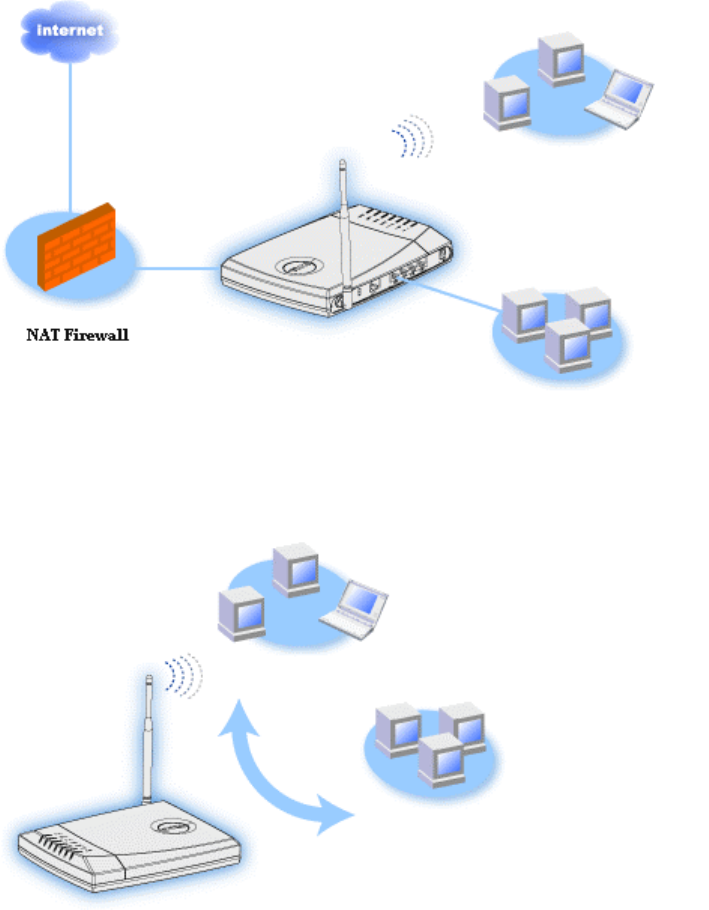
both wired and wireless computers. The firewall features included in the router control
Internet access and protect your network.
• Wireless hub (Access Point): Connects wireless computers for file and print sharing.
• 4-port Ethernet switch: Connects four wired computers for file and print sharing.
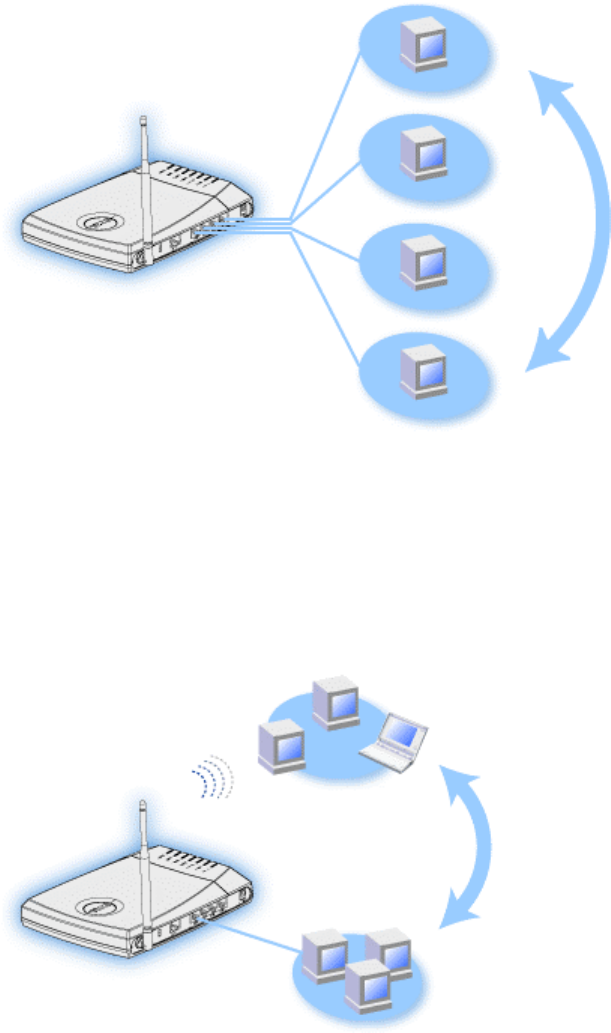
• Ethernet bridge: Enables file and print sharing between wired and wireless
computers. In addition, connects to an Ethernet hub, extending Internet connectivity
and sharing to more wired computers.
The router supports up to 252 clients. Up to 16 of the 252 clients can be wireless. The
Network Address Translation (NAT) feature allows 64 clients to simultaneously
communicate out to the Internet. It runs at speeds up to 54 Megabits per second (Mbps), and
the LAN (wired) port runs at 10/100 Mbps. The maximum distance between the router and
each computer is 300 feet. This distance may be less depending on your environment.
By default, you can use the router in the following ways:
• a wireless access point using wireless as the wireless network name.

• a DHCP server that provides IP addresses to wireless and wired clients.
• a bridge to an Ethernet hub.
Wireless Networking Overview
Wireless Local Area Network (WLAN)
Identifying a WLAN
Encryption
Automatic Rate Selection and Rate Scaling
Wireless Local Area Network (WLAN)
A Local Area Network (LAN) is a network in one location. Users at that location can share
files, printers, and other services. In a LAN, a networked computer that requests services is
called a client. A Wireless Local Area Network (WLAN) is a type of LAN that uses high
frequency radio waves rather than wires to communicate and transmit data among the network
clients and devices. It is a flexible data communication system implemented as an extension to,
or as an alternative for, a wired LAN.
In a WLAN, wireless adapters are installed in clients, also called wireless clients. The adapter
allows the wireless client to communicate with the WLAN without cables. Instead, wireless
clients send and receive information through a path in the air called a channel.
The standards for a WLAN are based on the IEEE 802.11b standard and proposed 802.11g
standard. All Dell 802.11b/g-compliant devices interoperate with other 802.11b/g -compliant
wireless devices from other vendors. The WiFi certification logo indicates that the wireless
device has been tested by an independent organization.
A wireless client operates in either infrastructure mode or peer-to-peer mode.
Back to Top
Identifying a WLAN

An ESSID and BSSID are both Service Set Identifiers (SSID) that identify and control the
wireless client’s access to a given WLAN. The SSID is sometimes referred to as the network
name. The SSID indicates what WLAN you are referring to. In most cases, the user interface
displays the SSID.
When installing an access point or wireless adapter in a wireless client, the installation
program asks you to enter the SSID. Dell cannot provide you with this information, as it is
specific to your network; but you may choose to use the default SSID, wireless, for your
Router. All wireless clients and access points in a WLAN must use the same network name.
Back to Top
Encryption
In a WLAN, wireless clients and access points send and receive information through the air.
Without implementing security, it is possible for an unauthorized person to intercept the
information.
A common way of implementing security and protecting information is encryption. Encryption
applies a set of instructions, called an algorithm, to information. The instructions combine the
plain or clear text of information with a sequence of hexadecimal numbers, called an
encryption key.
Before transmitting information over the airwaves, the wireless client or access point encrypts
or scrambles the information. The access point or wireless client receiving the information
uses the same key to decrypt or unscramble the information. The information is only readable
to WLAN devices that have the correct encryption key. The longer the key is, the stronger the
encryption.
The Router supports both Wired Equivalent Privacy (WEP) and Wi-Fi Protected Access
(WPA).
WEP
WEP (Wired Equivalent Privacy) provides a way of creating an encrypted key that is shared
between a wireless client (such as a notebook with a wireless PC card) and the router. In the
Router, WEP is an optional feature that can be enabled or disabled. When WEP encryption is
enabled, you must set the WEP key in the client to match the WEP key used by the access
point because you can ONLY connect to access points that have a matching WEP Key.

NOTE: It is better to change keys frequently. The same algorithm is used for all the
communications that should be protected. If the same key is used, the same
message will give exactly the same cipher text. Then, it will be possible for an
eavesdropper to break the encrypted data. For this reason, it is strongly
recommended to change keys often.
There are two WEP encryption methods:
• 40(64)-bit Encryption
• 104(128)-bit Encryption
40-bit and 64-bit encryption are identical. Some vendors use the term 40-bit; others use 64-bit.
A wireless device that claims to have 40-bit encryption interoperates with a device that claims
to have 64-bit encryption; the same is true for the reverse. A 40(64)-bit key consists of 10
hexadecimal numbers, arrayed as follows:
Key #1: 1011121314
Key #2: 2021222324
Key #3: 3031323334
Key #4: 4041424344
A 104(128)-bit key has several trillion times as many possible combinations than a 40(64)-bit
key. It consists of 26 hexadecimal numbers, arrayed as follows:
Key (#1): 101112131415161718191A1B1C
All wireless clients and access points in a WLAN must use the same encryption method and
key. The following two examples stress how important this point is.
Example 1
The encryption method for an access point is 40(64)-bit. The method for a wireless client is
104(128)-bit encryption. The client and access point cannot communicate with each other,
even though the selected key is the same. To resolve this problem, set the access point to use
104(128)-bit encryption.
Example 2

The encryption method is the same for the access point and wireless client. You select key 1
for the access point and key 2 for the wireless client. The wireless client cannot communicate
with the WLAN. To resolve this problem, select key 1 for the wireless client.
NOTE: Use the same key and encryption method for the wireless devices in the WLAN.
Otherwise, they cannot communicate with each other.
The Router uses either hexadecimal digits or ASCII characters to create encryption keys.
Hexadecimal digits include the numbers 0 to 9 and the letters A to F. For example, the decimal
number 15 is represented as F in the hexadecimal numbering system.
ASCII is the acronym for the American Standard Code for Information Interchange.
Pronounced ask-ee, ASCII is a code for representing English characters as numbers, with
each letter assigned a number from 0 to 127. For example, the ASCII code for uppercase M is
77. Most computers use ASCII codes to represent text, which makes it possible to transfer
data from one computer to another.
WPA
WPA (Wi-Fi Protected Access) is an upgrade to the WEP standard for securing your wireless
network. WPA is derived from and will be forward-compatible with the future IEEE 802.11i
standard. It provides improved data encryption and user authentication.
To enhance the level of security, WPA uses Temporal Key Integrity Protocol (TKIP)
encryption to address the vulnerabilities of the static keys used in WEP. TKIP includes four
algorithms: message integrity check (MIC), to protect packets from tampering; Per-Packet
Key (PPK) hashing, to prevent weak key attacks; extended initialization vector (IV), to
reduce IV reuse and the possibility that a hacker will collect sufficient packets to crack the
encryption; and a re-keying mechanism, to change the temporal key dynamically. TKIP is the
most commonly used encryption method; however, if your wireless clients do not support TKIP,
the Router also supports Advanced Encryption Security (AES) encryption. AES will replace
802.11's RC4-based encryption under the 802.11i specification. AES, the gold-standard
encryption algorithm, provides maximum security for wireless network.
For user authentication, WPA adopts an authentication scheme through 802.1x. 802.1x
provides a framework for user authentication and a key distribution management method.
802.1x consists of three main elements: an Authentication Server (typically a RADIUS server),
WPA-enabled router or AP (called Authenticator), and a WPA-enabled client (called
Supplicant). 802.1x ensures only authorized users can access the network.

In enterprises, WPA will be used in conjunction with both a wireless router and authentication
server. In a Small Office/Home Office (SOHO) environment, where there is no authentication
server, users can use pre-shared key (PSK) mode in place of the authentication server. The
Router offers you WPA running in PSK mode. The mutual authentication and improved
encryption technology of WPA allows wireless communication to achieve greater security.
Back to Top
Automatic Rate Selection and Rate Scaling
In 802.11g, wireless network adapters and access points can transmit data at one of the
following rates: 54, 48, 36, 24, 18, 12, 9, or 6 Mbps. In 802.11b, the data can be transmitted at
a rate of 11, 5.5, 2, or 1 Mbps. As the distance between an adapter and access point increases
or decreases, the data rate automatically changes. Other factors, like interference, also affect
the data rate. The Router uses automatic rate selection and rate scaling to determine the most
efficient rate of communication. Rate scaling maintains optimal communication between
wireless clients and the WLAN.
Back to Top
A Look at the Hardware
Front Panel
Back Panel
Front Panel
The Wireless Broadband Router has seven Light Emitting Diodes (LEDs), or link lights, on its
front side. The following table defines the behavior for each LED:
Front Panel
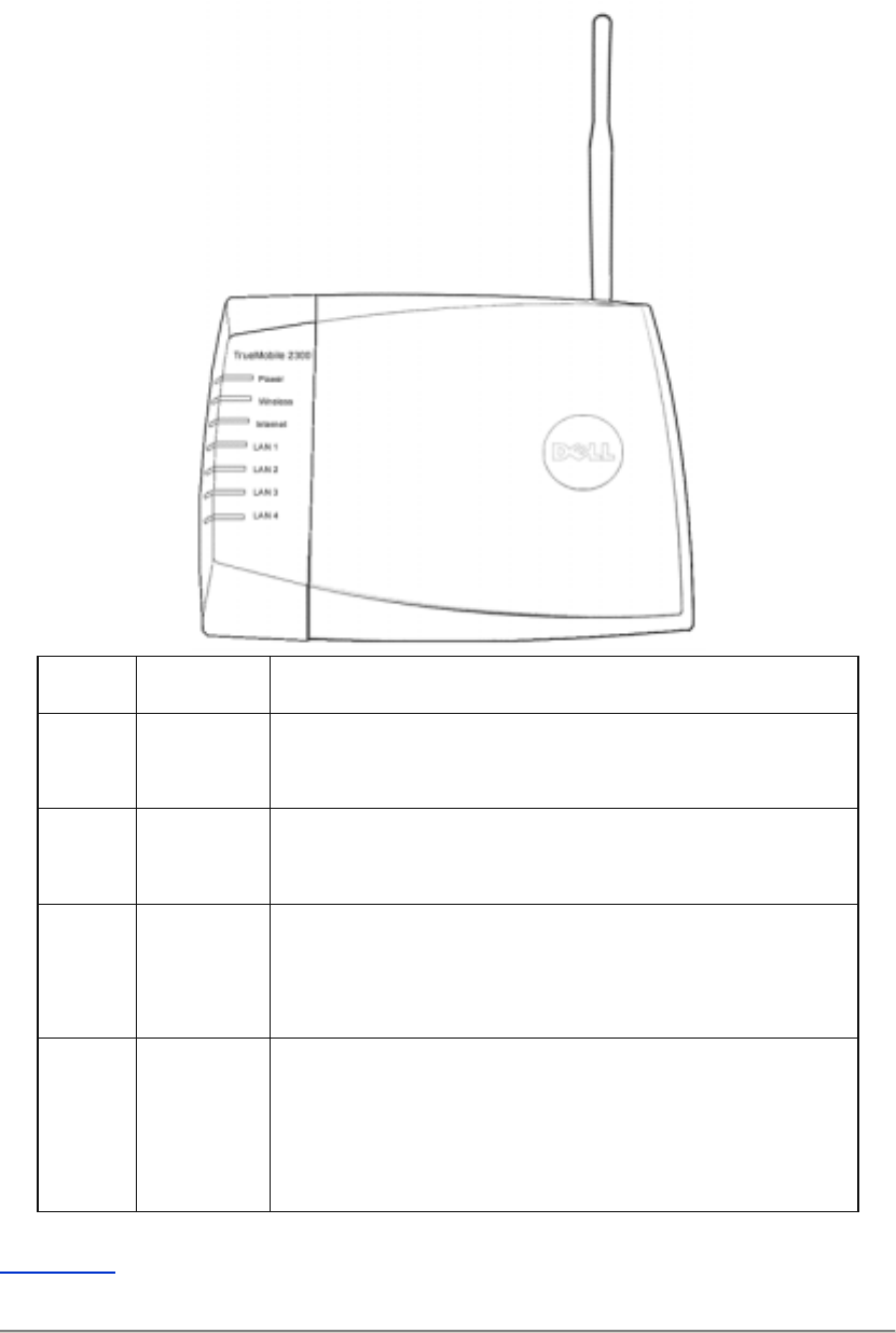
LED Represents Activity
Power Power The Power LED will light up when the device is powered on.
It will blink when the device is reset.
Wireless Wireless
LAN
The LED is steady on when there is at least one wireless
link connecting to the Router.
Internet DSL or
cable
modem
A steady green light indicates the connection is active, and
blinks with data activity.
A steady amber light indicates data collision.
LAN 1
LAN 2
LAN 3
LAN 4
Local Area
Network
A steady green light indicates the connection is active and
transfer rate is at 100Mbps.
A steady greenish amber light indicates the connection is
active and transfer rate is at 10Mbps.
Back to Top
Back Panel
Back Panel
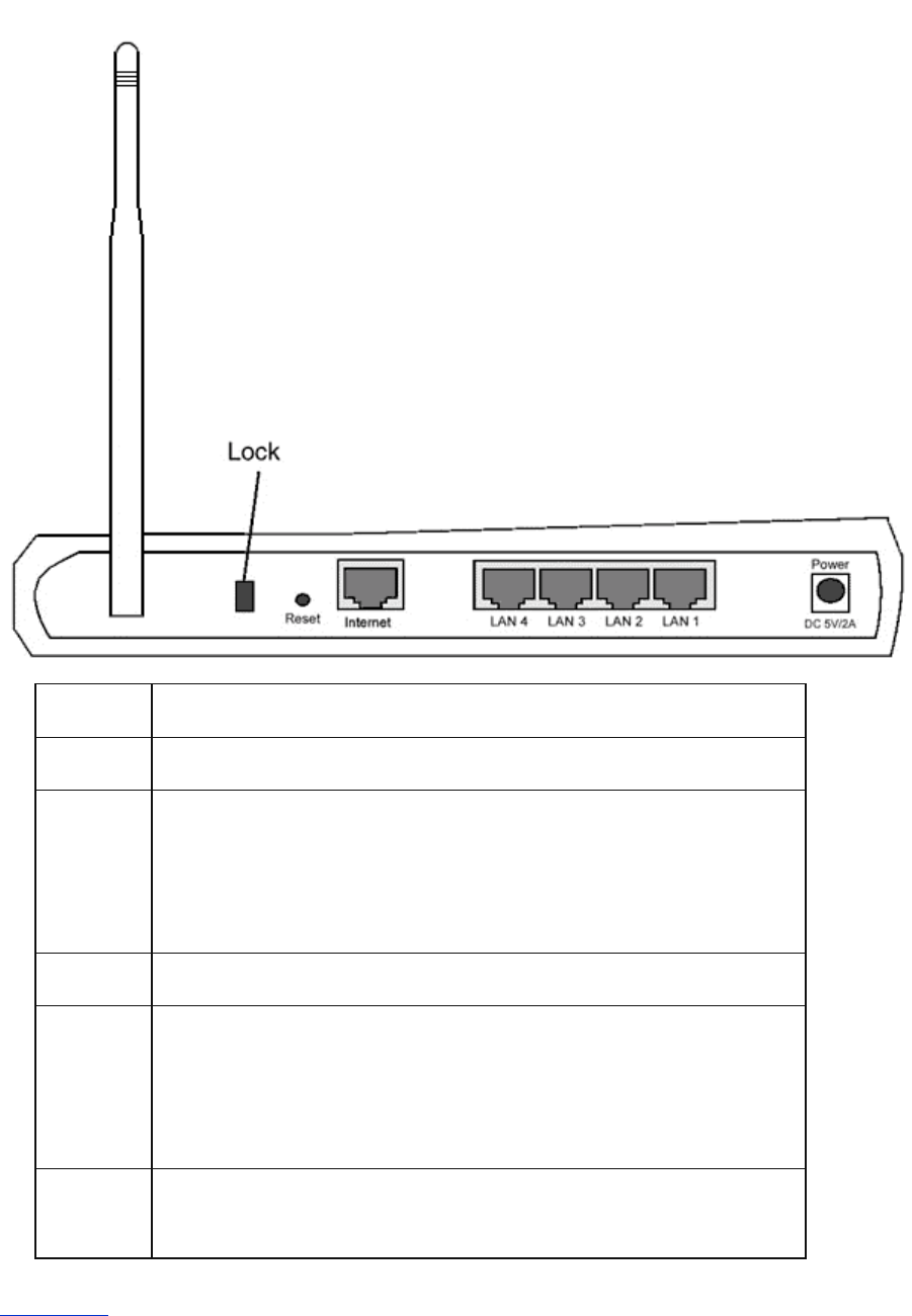
Connector Description
Lock This accepts locking devices for protecting the Router from theft.
Reset Use an object, such as a stretched paper clip, to press the button for at
least 3 seconds. The Power LED will be off for a short time and then
light up again. You can then release the button to reset the device to its
factory-default settings.
Internet This accepts an RJ-45 connector for network cabling.
LAN 1
LAN 2
LAN 3
LAN 4
This accepts RJ-45 connectors for connecting up to 4 computers to the
Router's 4-port switch.
Power Connect the power adapter to this Power port, and then plug the other
end of the power cable into a power outlet.
Back to Top

Using Your Router
Overview
Factory Default Settings
Setup Wizard
Control Utility
Web-Based Configuration Tool
Overview
Factory Default Settings: Your Wireless Broadband Router came with factory default settings
that should work for the majority of the network usage scenarios. However, there are cases
where your network environment may require a different router configuration.
Setup Wizard: Setup Wizard is a Windows-based software program included on your CD. You
can use this program to 1) install the router on your network and create an environment for
multiple computers to share Internet access, 2) add additional computers to the network, and 3)
provide links to the user's guide and the Dell support website.
Control Utility: Control Utility is a Windows-based software program included on your CD.
This utility is usually installed at the end of the router installation. It provides you with a useful
configuration tool to manage your Router. Refer to the section Control Utility for detailed
information.
Web-Based Configuration Tool: The web-based configuration tool is for advanced
configuration of the Wireless Broadband Router. It is a tool provided inside the router which
can be accessed via the web browser on your computer. This tool includes every basic and
advanced configuration option for the Router. For instance, you can allow other Internet users
to access a Web server hosted on your local private network, or disable your wireless network.
NOTE: Setup Wizard or Control Utility must be run on Windows 2000 and Windows XP
computers. Microsoft Internet Explorer 4.0 or higher or Netscape 4.0 or higher must
be used for the web-based configuration tool.
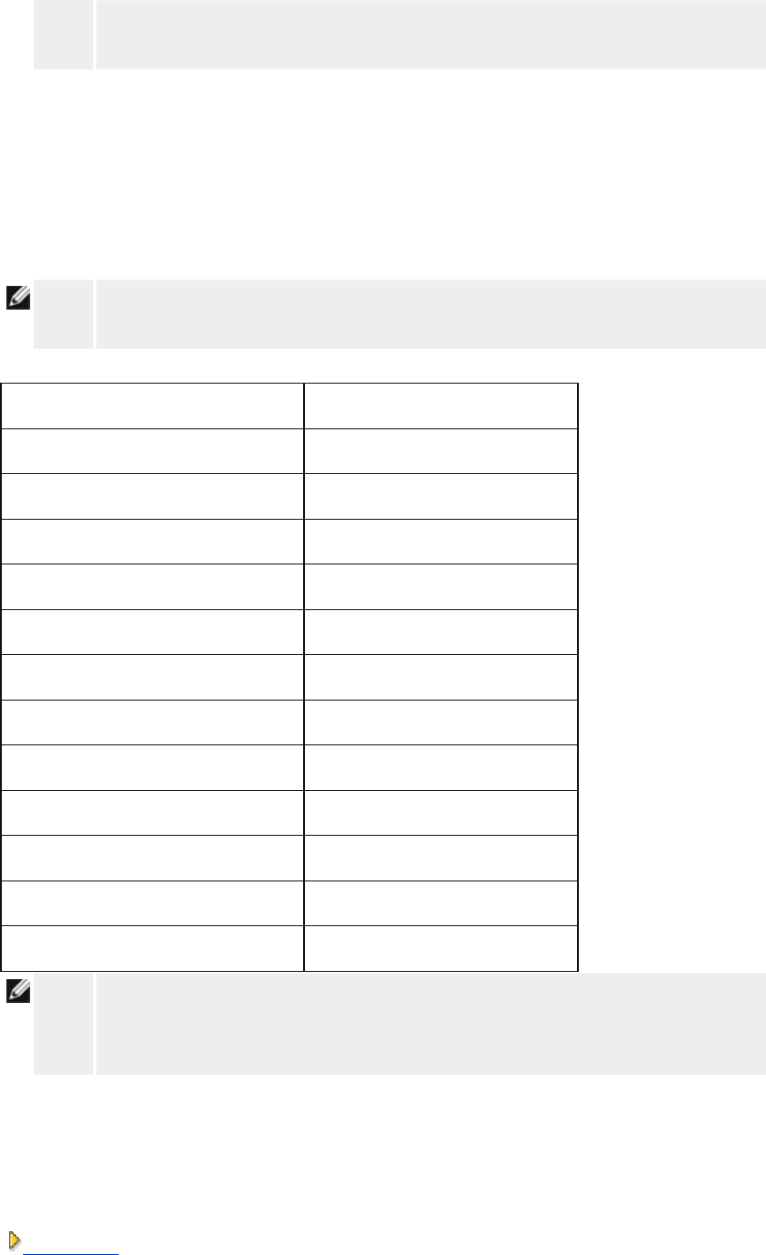
Factory Default Settings
Dell pre-configures the Router with the following settings:
NOTE: If you lose track of the device settings, you can reset the router by pushing the
reset button to restore these settings back to your router.
Setting Default
User Name admin
Password admin
Device Name my router
IP Address 192.168.2.1
Subnet Mask 255.255.255.0
10 Mbps Ethernet WAN IP <obtain from ISP via DHCP>
WAN DHCP Client Enabled
ESSID (wireless network name) wireless
Channel 6
Encryption No Encryption
DHCP Server Enabled
NAT Routing Enabled
NOTE: Your Wireless Broadband Router came with factory default settings that should
work for the majority of the network usage scenarios. However, there are cases
where your network environment may require a different router configuration.
Setup Wizard
Introduction

Launch the Setup Wizard
Setup Wizard Screens
Introduction
Setup Wizard is an easy-to-use program included on your CD. It provides simplified
configuration procedures for establishing Internet connectivity on the Router. The Setup
Wizard first extracts the connection settings from your active ISP connection on your computer
with a cable/DSL modem. It then displays a series of graphical illustrations on how to connect
the router to the network. Finally it applies the extracted settings on your router and validates
its installation. If the installation cannot be completed successfully, the Setup Wizard will
display troubleshooting instructions to guide you through the installation process.
In addition, the Setup Wizard also provides links to the user's guide on the CD and the Dell
support website.
Back to Top
Launch the Setup Wizard
To run the Setup Wizard, perform the following steps:
Insert the CD
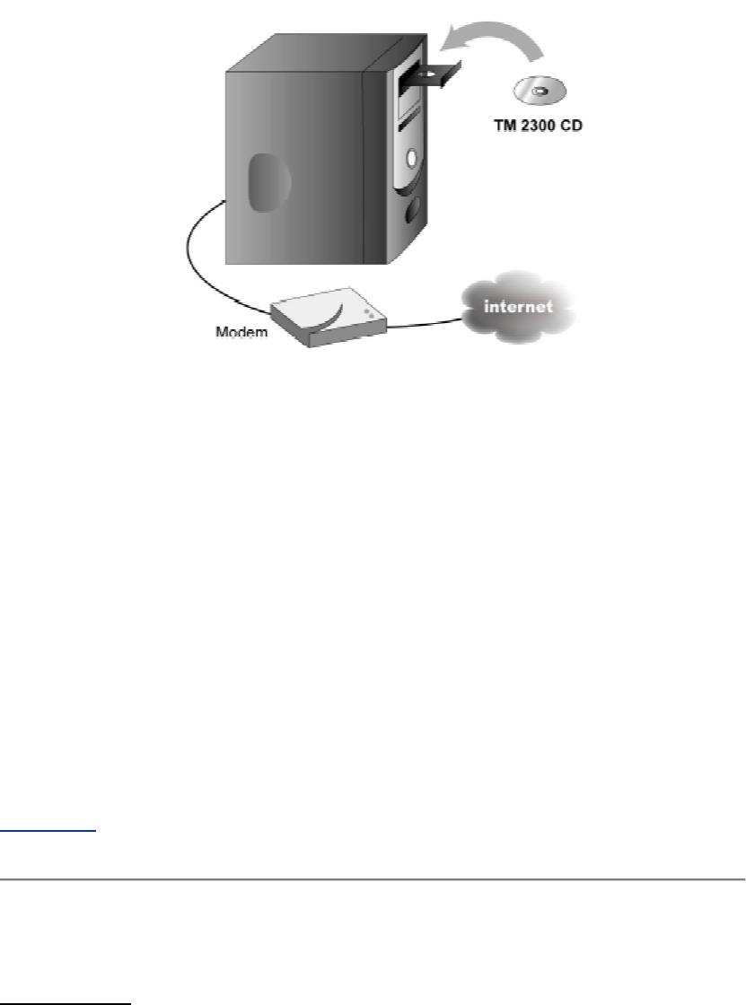
1. Insert the Wireless Broadband Router Setup CD into the CD drive on a computer
that is connected directly to the Internet.
Your CD should automatically launch the Setup Wizard. If it does not, complete the
following steps to start the Wizard.
a. Click the Start button, and then click Run.
b. Type the following text in the Open: field:
X:\setup.exe
where X is the drive letter of your CD drive.
Once the Setup Wizard has been launched, you will be guided through a series of windows.
These windows are illustrated below along with an explanation on their functionalities.
Back to Top
Setup Wizard Screens
Welcome Menu
This menu offers several options to select from.
• Installation
Begin installing your router and configure computers for Internet connectivity
• User's Guide
View the user's guide (this document)
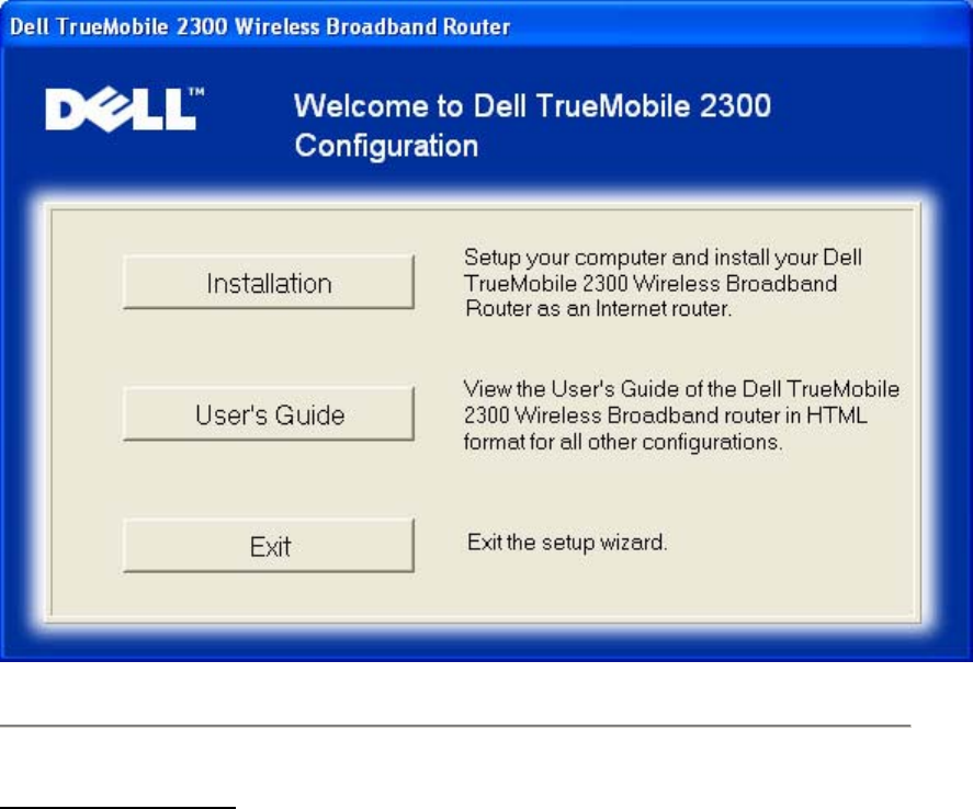
• Exit
End the Setup Wizard
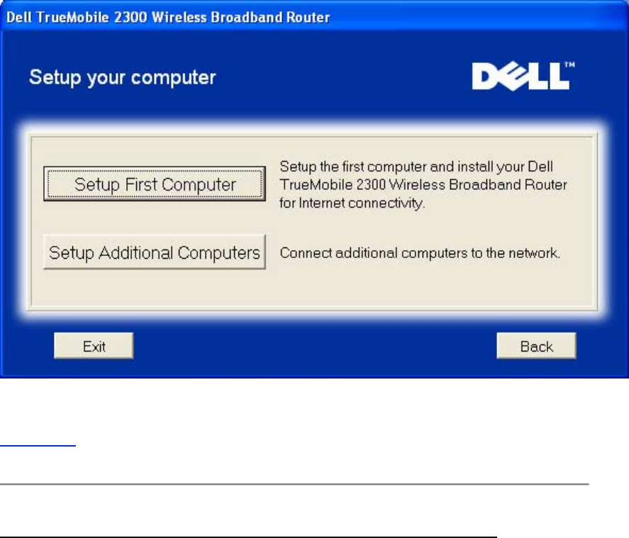
Welcome
Set Up Your Computer
• Click Setup First Computer if you want to install the router on the computer that is
used to connect to the Internet with a cable or DSL modem.
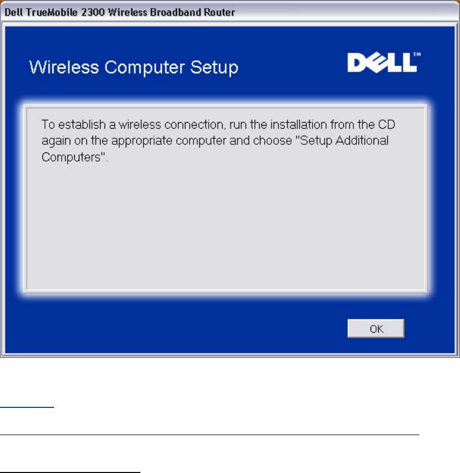
• To connect additional computers to your network after you have successfully installed
the router using the Setup First Computer option, place the CD in each additional
computer and run the Setup Wizard.
Click Setup Additional Computers to add each additional computer to your network.
Setup your computer
Back to Top
Verify Internet Connection on Your Computer with a Cable or DSL Modem
Verify Internet Connection
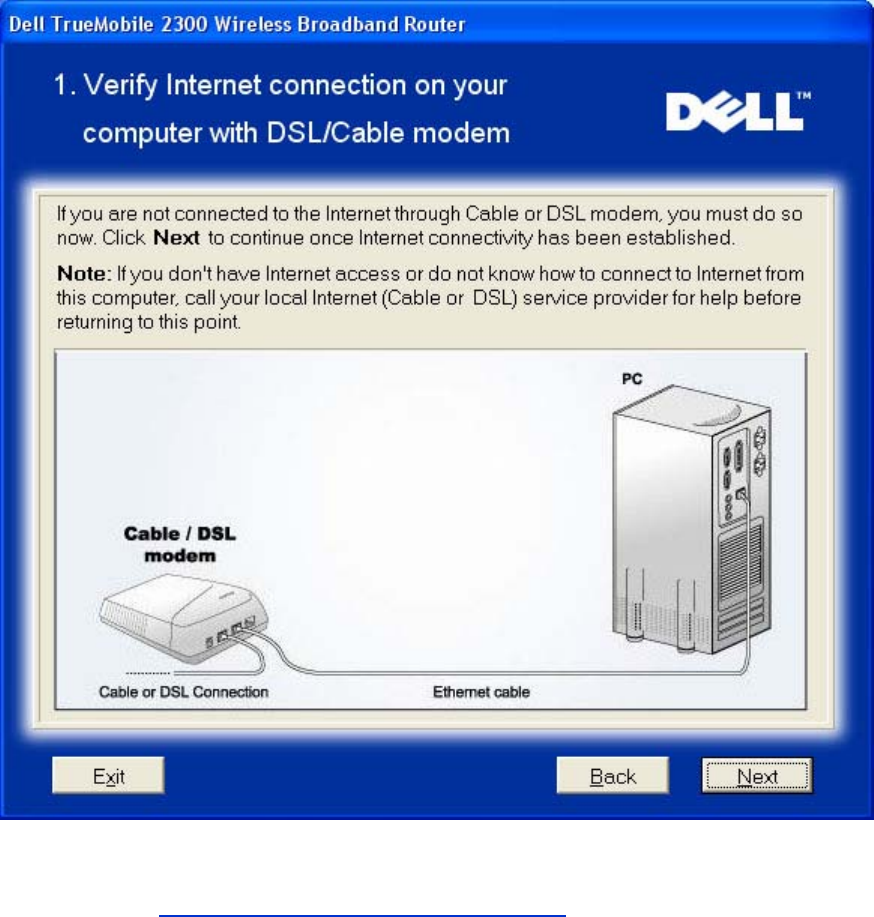
If you are using a PPPoE (Point to Point Protocol over Ethernet) connection, your computer
will then need to reboot.
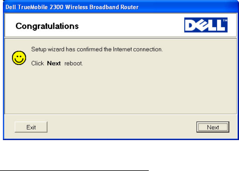
Congratulations
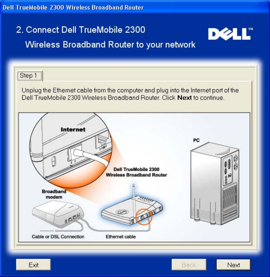
Connect Wireless Broadband Router to Your Network
Step 1 illustrates how the modem is connected to the Router.
Connect Router to Network: Step 1
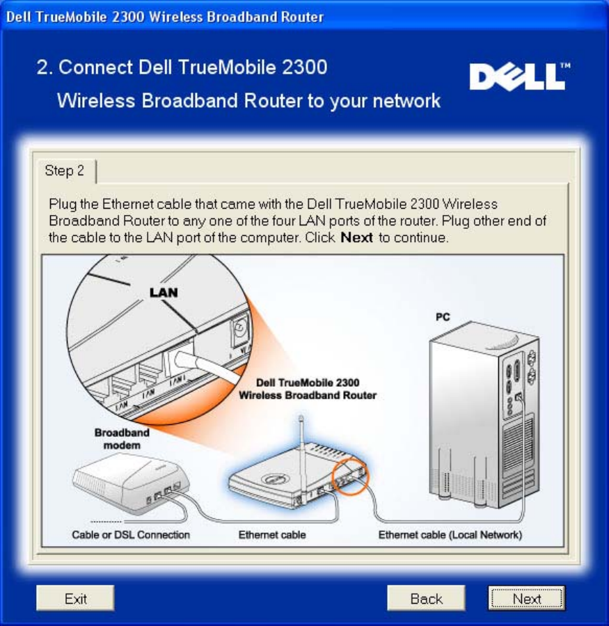
Step 2 illustrates how the router is connected to the computer.
Connect Router to Network: Step 2
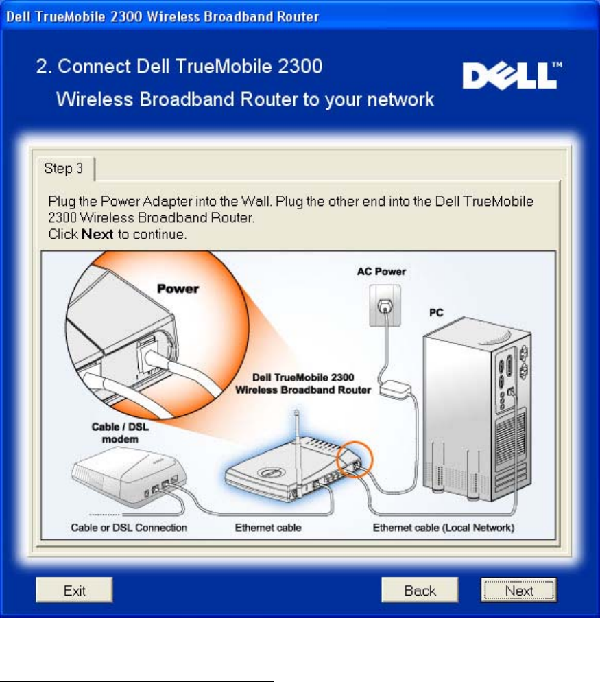
Step 3 illustrates how the Router is connected to the power supply.
Connect Router to Network: Step 3
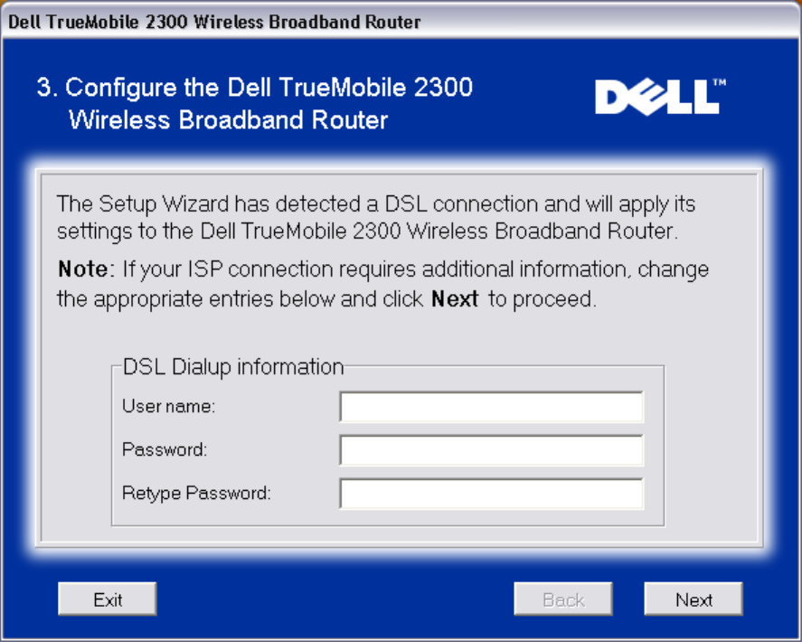
Configure the Wireless Broadband Router
If you are using a PPPoE connection, type your PPPoE username and password in the box.
PPPoE
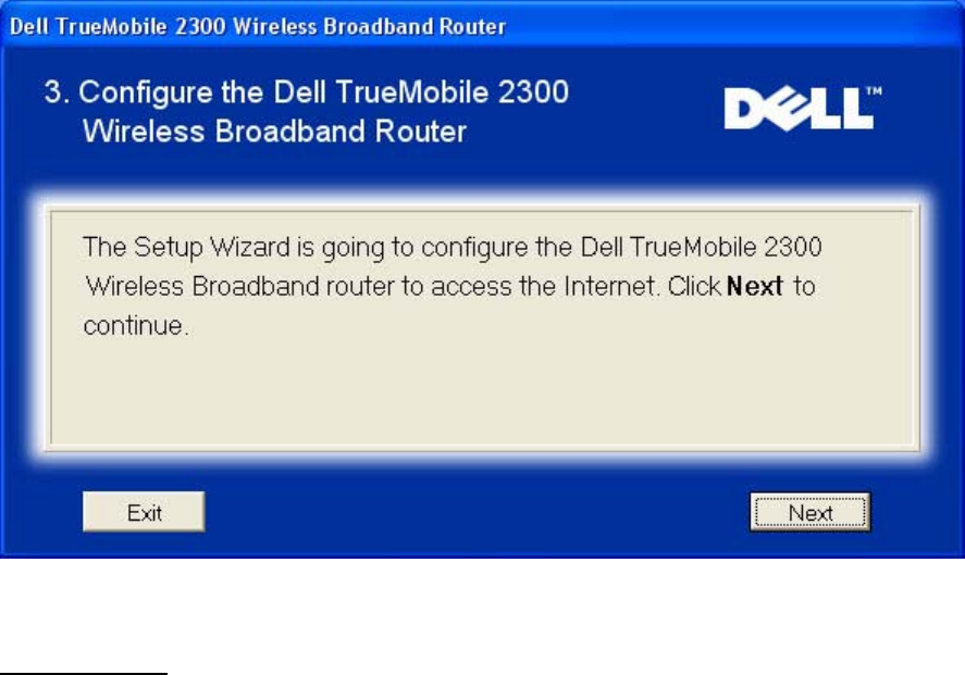
The Setup Wizard will apply the Internet connection settings to your Router when you click the
Next button.
Configure Router
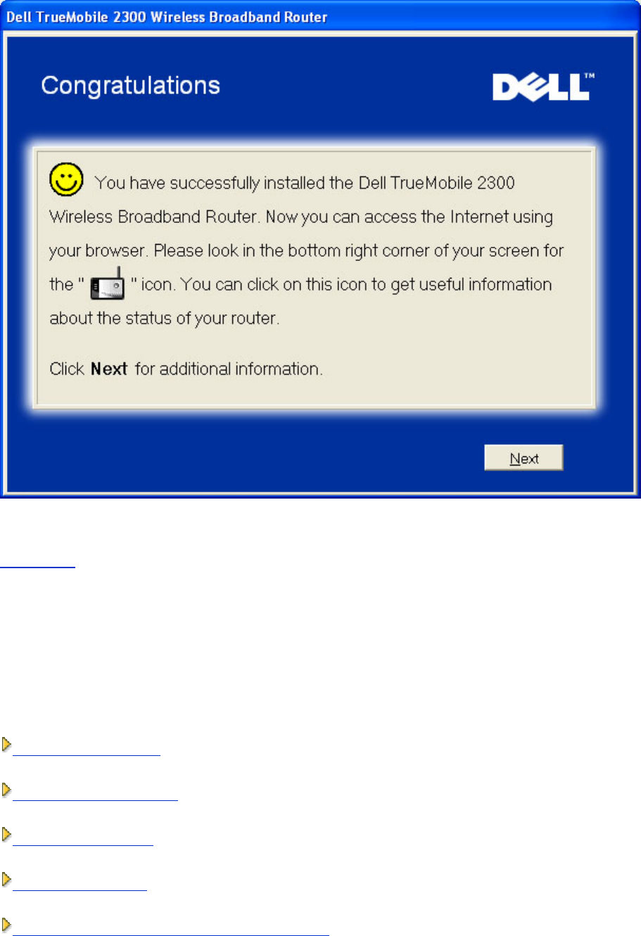
Congratulations
You have successfully installed the Router and configured the first computer for Internet
access.
Congratulations
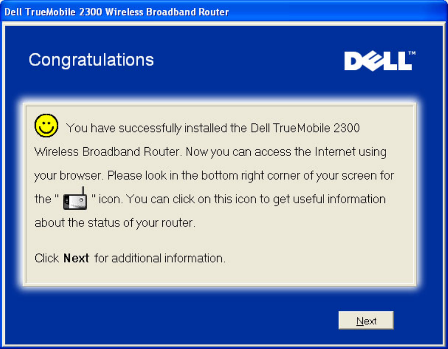
The Wireless Computer Setup window provides information on wireless settings and how to
enhance the security of your router.
Wireless Settings Overview
Back to Top
Set Up Additional Computers
Click to select your connection type.
Connection Type
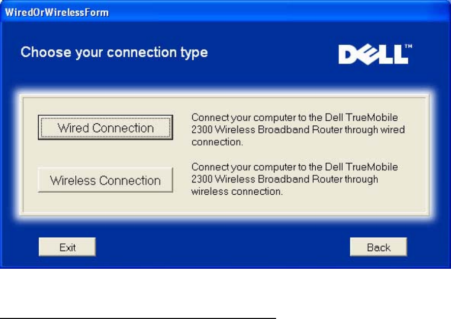
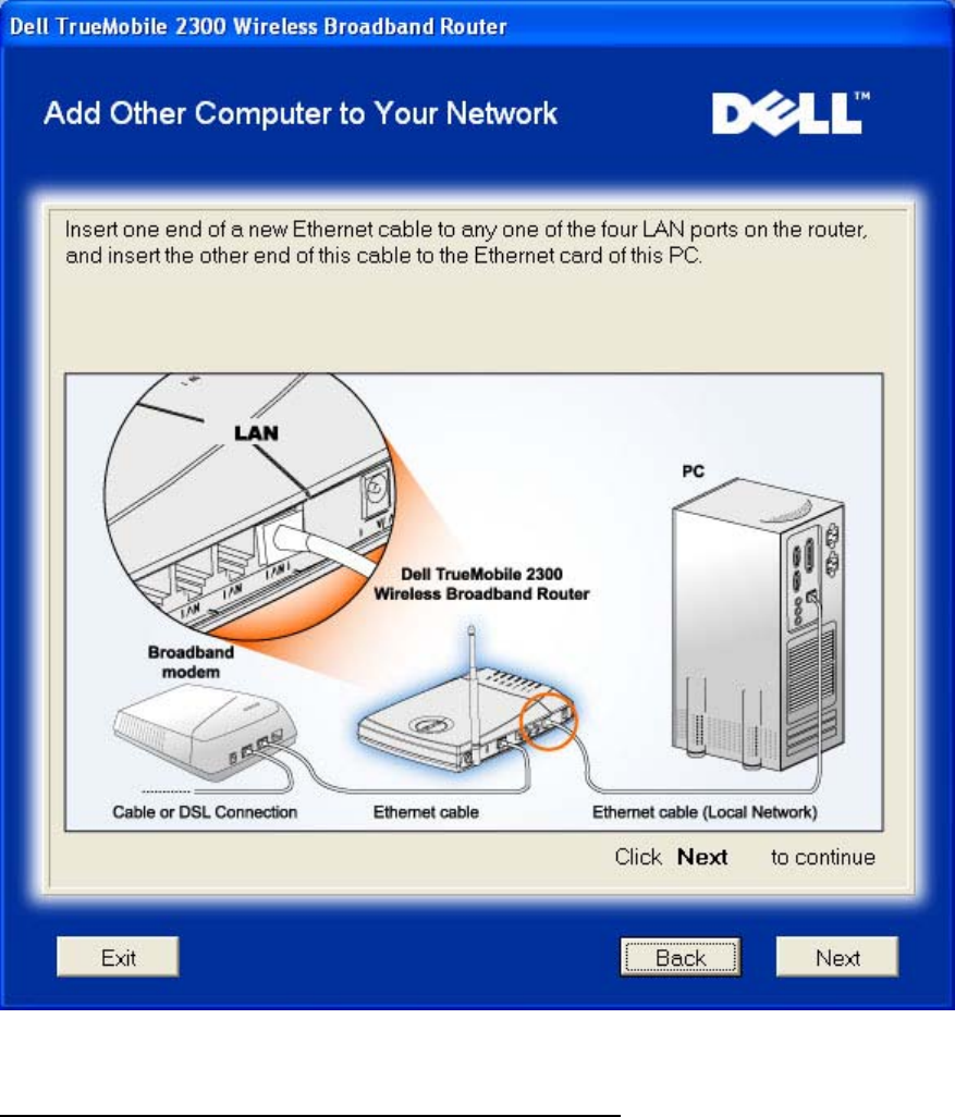
Add Other Computer to Your Network: Wired Connection
Pressing the Wired Connection button displays instructions to connect computers to the
network through Ethernet cable.
Add Computers
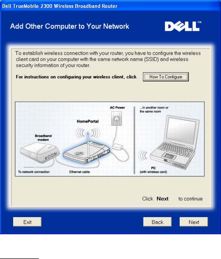
Add Other Computer to Your Network: Wireless Connection
Pressing the Wireless Connection button displays instructions to connect computers to the
network through a wireless channel.
Add Computers
Congratulations
You have successfully connected a computer to the network.
Congratulations
Back to Top
Control Utility
The Control Utility is Windows-based software that allows you to configure your router and
monitor the status of the connection from your computer to the Router and to Internet.
Install the Control Utility
Uninstall the Control Utility
Start the Control Utility
Exit the Control Utility
How to Configure the Router by the Control Utility?

Install the Control Utility
You can install the Control Utility on your computer when you step through the setup process
using the Setup Wizard.
1. Insert the Wireless Broadband Router Setup Wizard and User Guide CD into the CD
drive. Your CD should automatically launch the Setup Wizard program. If it does not,
complete the following steps to start the Wizard.
a. Click the Start button, and then click Run.
b. Type the following text in the Open: field:
X:\setup.exe
where X is the drive letter of your CD drive.
c. Click the OK button.
2. From the main menu, click the Installation button, and then click either the Setup
First Computer button or the Setup Additional Computers button.
3. Follow the on-screen instructions.
Back to Top
Uninstall the Control Utility
1. If the icon is displayed in the system tray in the lower right corner of the screen,
right-click the icon and click Exit.
2. Click the Start button.
3. Click Control Panel.
The Control Panel window appears.
4. Click the Add/Remove Programs icon.
5. Click to select the Control Utility from the program list and remove it as instructed.
Back to Top
Start the Control Utility

The control utility program will run automatically upon each computer startup by default. If the
utility does not start automatically, run the Wireless Broadband Router Dell Control Utility
from the Start menu.
Once running, a router icon is created in the system tray in the lower right corner of your
screen. If you have a good connection to the Internet, the system tray icon looks gray and
white . You can double-click the router icon to open the utility panel.
NOTE: If the icon is yellow , it indicates that the Internet connection is not active. If the
icon is red , it indicates that the connection to the router failed.
Back to Top
Exit the Control Utility
When you start the control utility program, it will place a small gray and white icon in the
system tray in the lower right corner of your screen. If you want to exit the program, right-click
the icon, and then left-click Exit to quit the program.
Back to Top
How to Configure the Router by the Control
Utility
My Network Overview
Wireless Settings
Network Access Control
Gaming
Remote Access
Administration
Diagnostics

Advanced Settings
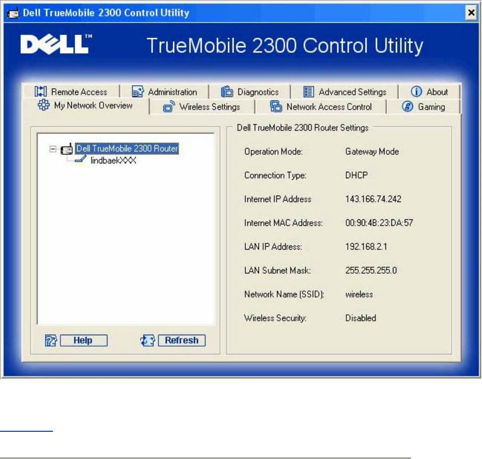
My Network Overview
This screen provides information about your network connection and settings. The left pane
displays your connection status. The right pane displays the following network settings:
• Operation Mode
• Connection Type
• Internet IP Address
• WAN MAC Address
• LAN IP Address
• Netmask
• Network Name (SSID)
• WEP Functionality
My Network Overview
Back to Top
Wireless Settings
• Network Name (SSID)
The SSID is a unique network name. It is used to identify the WLAN. This name is
used when connecting additional computers to your wireless router.
• Channel
This is the radio channel over which a communication transmission occurs.
• Factory Default Value
Resets the wireless settings to its factory defaults.
• Apply
Saves current settings.
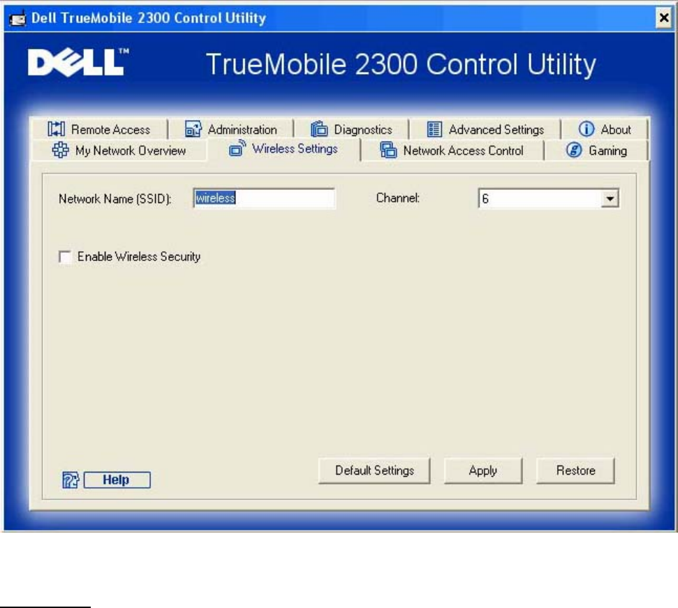
• Restore
Restores previous settings.
Your router has an advanced security mechanism. It ensures the confidentiality of data, and
also guards data against being modified. If you want to enable the security mechanism, click to
select Enable Wireless Security.
Wireless Settings
WEP Settings
Wired Equivalent Privacy (WEP) encryption used in the 802.11 standard is to protect
wireless communication from eavesdropping. WEP provides a way of creating an encrypted
key that is shared between a wireless client (such as a notebook with a wireless PC card) and
the router. This key encrypts data before it is transmitted. WEP can be implemented with a

40(64)-bit or 104(128)-bit key. For added security, change your key often. When you change
the key on one wireless device, it must be changed for all wireless devices and Access Points
in the network.
• Key Format
Can be ASCII or hexadecimal format. Hexadecimal format includes the numbers 0
through 9 and the letters A through F. ASCII format includes all alphanumeric
charcters.
• Key Length
Can be either 40(64)-bit or 104(128)-bit key length. Some wireless network cards are
only able to use 40(64)-bit encryption. If all your clients are able to communicate at
104(128)-bit, then choose 104(128)-bit. If any client is only able to communicate at
40(64)-bit, choose 40(64)-bit.
• Key1, Key2, Key3, and Key4
Type four different keys in the Key fields provided to store on the Router. If you
choose 40(64)-bit encryption, enter a 5-character (or 10 hexadecimal digits). For
104(128)-bit encryption, enter a 13-character (or 26 hexadecimal digits) WEP key.
• Default Key
Select only one key out of the four provided in the Default Key field.
WPA Settings
Wi-Fi Protected Access (WPA) is an upgrade to the WEP standard for securing your wireless
network.
If you would like to secure your wireless network using WPA, you must have WPA support for
your wireless clients. If you are using a Dell TrueMobile wireless client, you can check for the
availability of WPA-enabled software updates for your wireless client at http://support.dell.com.
• WPA Pre-shared Key
All wireless clients must use this key to gain access to the network. Note that the Key
format must also match the setting for the wireless clients.
• Key Format
Can be ASCII or hexadecimal format. Hexadecimal format includes the numbers 0
through 9 and the letters A through F. ASCII format includes all alphanumeric
charcters.
• WPA Group Rekey Interval
WPA Group Rekey Interval is used to specify the frequency of encryption key rotations.

The lower the number, the faster your encryption key will rotate; however, setting this
number too low may cause your wireless network to slow down.
• WPA Encryption
TKIP (Temporal Key Integrity Protocol) is the most commonly used encryption method.
AES (Advanced Encryption Standard) can be used if your wireless clients do not
support TKIP.
Back to Top
Network Access Control
• Add
Adds a new entry to the list.
• Edit
Allows you to edit entries.
• Delete
Deletes a record from the list.
• Delete All
Deletes all records from the list.
• Restore
Restores previous settings.
Network Access Control
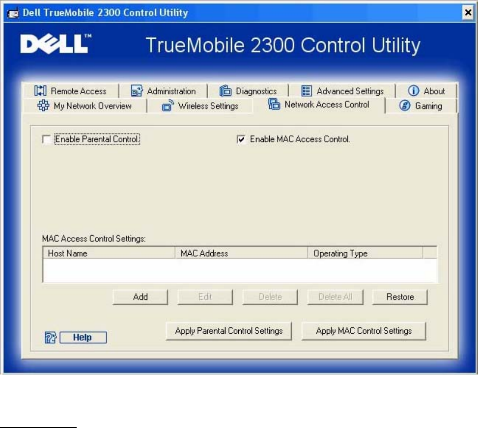
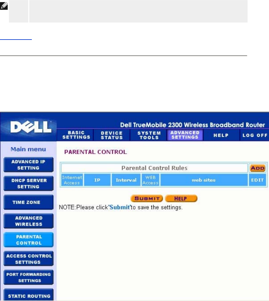
Parental Control
Parental Control allows you to determine what type of websites are accessible through your
wireless network. It also allows you to specify what time of day the Internet can be accessed.
To enable parental control, perform the following steps:
1. Click to select Enable Parental Control.
2. Click the Add button.
The Parental Control window appears.
3. Enter the IP address of the computer you want to control (for example, your child's
computer) in the Host IP field.
4. Select Allowed or Denied from the Internet Access list.
5. Enter a time Interval, during which users will be allowed to access the Internet.
6. Select allow or deny for web access.

7. Specify which websites may be accessed or may not be accessed by entering their
URLs in the Website URL field.
8. Click the OK button to apply, or click the Cancel button to exit without making any
changes.
9. Click the Apply Parental Control Settings button on the bottom of the screen to
activate the new settings.
MAC (Media Access Control)
This feature prevents specific computers within the wireless local area network (WLAN) from
accessing the Internet.
To enable MAC, perform the following steps:
1. Click to select Enable MAC Access Control.
2. Click the Add button.
The MAC Access Control: Add Entry window appears.
3. Enter the hexadecimal MAC address (for example, 00:11:22:33:44:55) that you want
to grant or deny access in the Host MAC box.
4. Select Grant or Deny from the Operating Type list.
NOTE: The operating type for ALL records MUST be either Grant or Deny.
5. Click the OK button to apply, or click the Cancel button to exit without making any
changes.
6. You can click on the selected record and click again on its Host Name to enter the
desired name for this record.
7. Click the Apply MAC Control Settings button on the bottom of the screen to activate
the new settings.
Back to Top
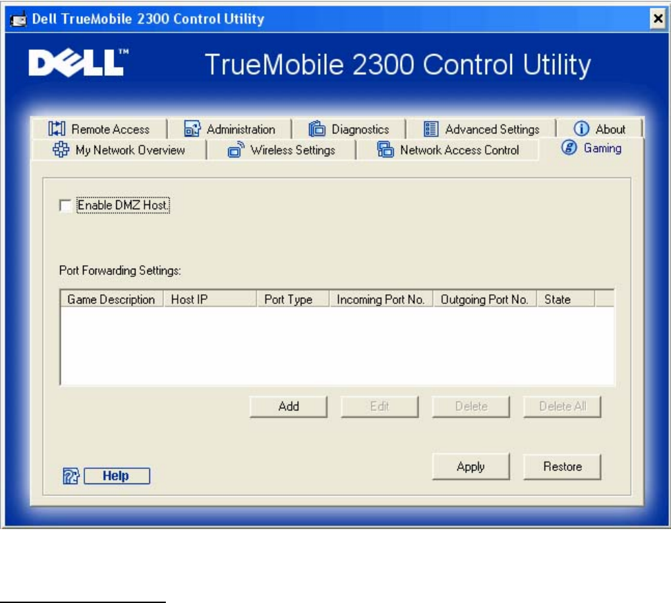
Gaming
In some cases, the firewall feature of the router will cause a game not to function as intended.
The settings listed on the Gaming menu can solve these problems.
Your Router has an integrated Network Address Translation (NAT) firewall that rejects any
unsolicited data from the Internet to access the computer on your LAN. Applications like e-mail
and web browsing are unaffected by NAT. However, some applications (such as Internet
messaging and gaming applications) will not function correctly.
Gaming
Port Forwarding Settings
Port forwarding allows you to configure your router to accept unsolicited data through a specfic
port. The ports and protocol type (TCP, UDP, or both) will depend on what gaming service you
are using.
To enable Port Forwarding, perform the following steps:
1. Click the Add button.
The Gaming: New Record window appears.
2. Type the desired name or description in the Game Description field.

3. Type the IP address of the device (for example, desktop computer) for gaming in the
Computer IP for gaming field.
4. Select a transport layer protocol from the Protocol Type list. The options listed here
are TCP (Transmission Control Protocol), UDP (User Datagram Protocol), and both.
5. Enter the incoming port number in the Incoming Port No. field and the outgoing port
number in the Outgoing Port No. (also called Destination Port) field.
NOTE: This information should be available from your gaming service.
6. Select Enable or Disable the gaming from the State list.
7. Click the OK button to apply, or click the Cancel button to exit without making any
changes.
DMZ
Some applications experience problems when working behind a firewall. To solve this problem
you can put computers outside of the firewall via the router's DMZ (demilitarized zone) feature.
The DMZ feature disables the NAT firewall and allows all data to pass through all ports to this
computer.
Follow the instructions below to enable the DMZ feature.
1. Click to select Enable DMZ Host.
2. Type the IP address of the computer that will run the gaming application in the DMZ IP
Address field.
3. Click the Apply button to apply the new settings.
Back to Top
Remote Access
Remote Access
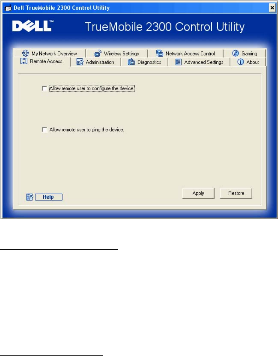
Allow Remote User to Configure the Device
This option allows you to configure the device from a remote location via the network.
1. Click to select Allow remote user to configure the device.
2. Enter the IP address of the remote administration host in the required field.
3. Enter the HTTP port number that will be used on the router in the HTTP port number
field.
4. Click the Apply button to save the settings, or click the Restore button to restore to its
previous settings.
Allow Remote User to Ping the Device
This option allows you to configure the WAN ping capability. The default setting is disabled.
The router will not answer ping requests, so your WAN port is invisible to port scanners, which
can make your network safer.
1. If you want your WAN port to be visible on the Internet, click to select Allow remote
user to ping the device.
2. Click the Apply button to save the settings, or click the Restore button to restore to its
previous settings.
Back to Top
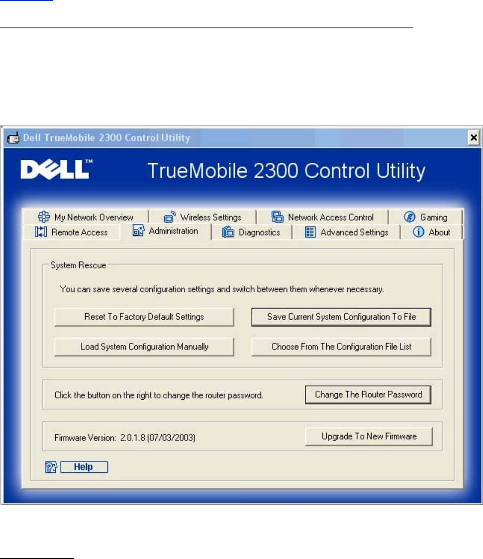
Administration
Administration
System Rescue
System Rescue allows you to save a backup of your configuration settings.

• Save Current System Configuration To File
Saves the current settings as a .pro file.
• Load System Configuration Manually
Loads the backup file to restore previously saved settings.
• Choose From The Configuration File List
The router will automatically save a copy of backup configuration files in the file list.
You can select a file to load from the list, instead of searching for the correct file.
• Reset to Factory Default Settings
Resets the router to its default configuration.
Change Password
To prevent unauthorized changes to the router settings, the router is password protected. It is
strongly recommended that you change the factory default password.
1. Click the Change Password button.
The Password Settings window appears.
2. Type the original password in the Original Password field.
3. Type the new password in the New Password field, and then retype it in the Confirm
Password field to verify.
4. Type the password hint message in the Password Hint Message field.
5. Click the Submit button when you finish the setting. If you want to clear any values
you have entered in any field, click the Cancel button.
Upgrade to New Firmware
If you are instructed to upgrade the firmware, click the Upgrade to New Firmware button. It
will connect to the Dell website to upgrade to the latest firmware release. It is unnecessary to
upgrade the firmware if your router is working properly.
Back to Top
Diagnostics
Diagnostics
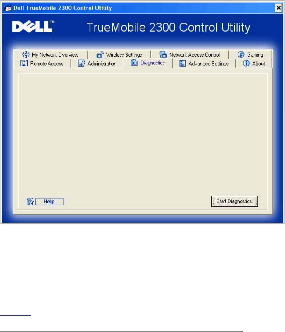
You can monitor the current status of your network connection in the Diagnostics menu. The
network detection can be activated by clicking the Start Diagnostics button on the bottom of
the screen.
When the detection is done, the screen will display a summary of your Internet connectivity.
Back to Top
Advanced Settings
To configure the advanced settings of the router, click the Login button to log in to the
web-based configuration tool. The web-based configuration tool allows you to set up advanced
network configurations for your Wireless Broadband Router.
Back to Top
Web-based Configuration Tool:
Dell™ TrueMobile™ 2300 Wireless Broadband
Router User's Guide
Overview
Basic Settings
Device Status
System Tools
Advanced Settings
Log Off
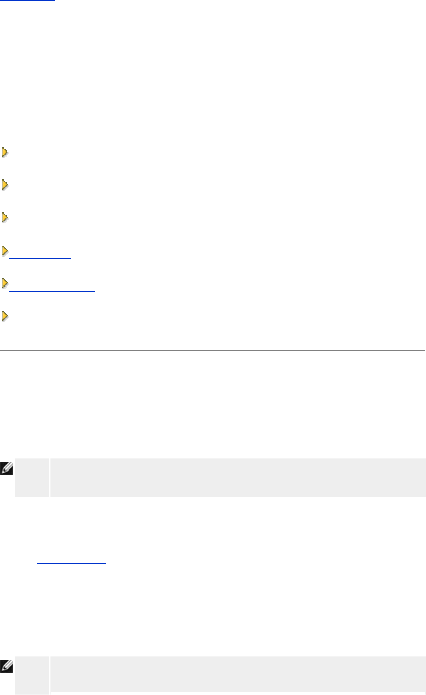
Overview
The web-based configuration tool enables you to set up advanced network configuration for
your Wireless Broadband Router. Follow the instructions below to gain access to the web tool.
NOTE: Microsoft Internet Explorer 4.0 or higher or Netscape 4.0 or higher must be used for
the web-based configuration tool.
1. Click the Start button, and then click Run.
2. Type the following text in the Open box:
http://my.router
3. If this is the first time configuring your Router, or if the user name and password have
not been changed, type admin in the User Name and Password fields.
4. Click the OK button.
The Configuration screen appears.
NOTE: Dell technical support representatives do not support the configuration options in
the Advanced Settings portion of the configuration program. These options are
provided for your convenience only. However, the advanced settings are fully
documented and explained in this guide.
Main Menu
Back to Top
Log Off
The web-based configuration tool only allows access to one user at a time.
Back to Top
Basic Settings: Dell™ TrueMobile™ 2300
Wireless Broadband Router User's Guide
The following configuration options are included in Basic Settings:
Router Mode
Wireless Settings
Wireless Security
Internet Connection Settings
Save & Apply
NOTE: To implement the changes you make to the settings, you must save your settings
and restart the router. Otherwise, the router uses the previous settings. If you are
using the BACK/NEXT links to step through each screen in the Basic Settings
portion of the web-configuration tool, you ultimately reach the Save & Restart
page. Click Save & Restart to commit the changes, and the router will reboot
automatically with the new settings in effect.
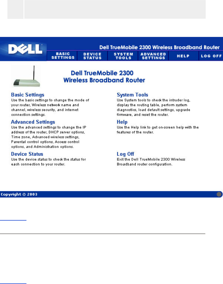
Router Mode
The router has two operating modes: Gateway mode and Access Point mode.
Router Mode

Gateway mode allows your router to create a wireless network to access the broadband router.
Wired and wireless network devices share the same Internet connection through Internet port
in the Gateway mode. However, some ISPs may request you to do the additional setup, such
as PPPoE, before using your router to access the Internet.
Access Point (AP) mode allows your router to act as a bridge between wireless devices and
Ethernet devices in the existing network. All wired and wireless devices are located in the
same class C subnet. Internet port is useless here. Thus, Access Point mode is here to help
you set up a single isolated network.
NOTE: If the device is put in AP mode, the Internet Connection Settings will not be
available.
The Gateway mode is the default setting in Router.
Back to Top
Wireless Settings
Wireless Settings
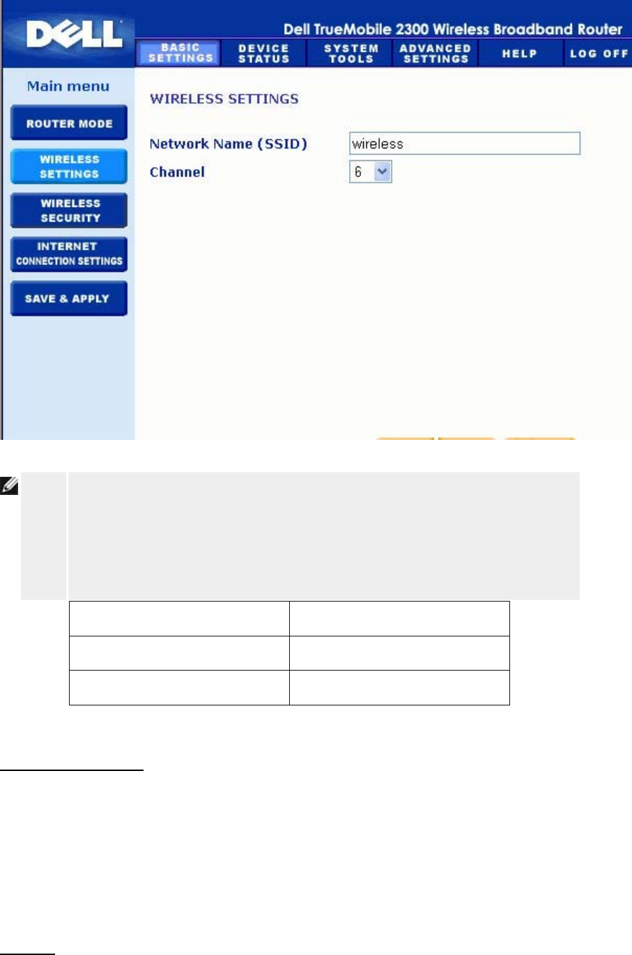
NOTE: You must change each client’s wireless adapter settings to match the Router
settings. Use the factory defaults for the Router, unless the default settings have
been changed. In this case, note the changes and use the new settings for each
wireless network card. For assistance configuring a wireless network card, see the
card’s documentation.
Setting Possible Values
Network Name (SSID) (wireless by default)
Channel (6 by default)
Network Name (SSID)
The network name is a value that identifies a collection of wireless devices found in a
particular network. The default value for the Router is wireless. All workstations and access
points must use the same SSID to be able to communicate with one another.
The SSID is a 32-character field, and the value is case sensitive.
Channel
The Router can operate on a variety of channels. Routers within close proximity to one another
must be on different channels. If you have just one router, then the default, channel 6, is
probably adequate. If you have multiple access points in your network, it is suggested to
stagger the channels for each router. It is advisable to use the default unless there is a specific
reason for changing the channel, such as interference from microwaves, cellular phone towers,
or other access points in the area.
Back to Top
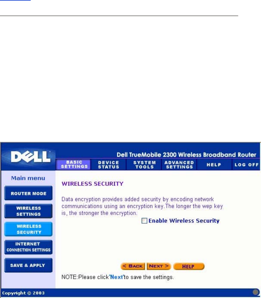
Wireless Security
Data encryption provides added security by encoding network communications using an
encryption key. Your Router, in conjunction with wireless network adapters that support
encryption, can scramble your transmitted data to make it difficult for someone to eavesdrop or
intercept your information. Two methods of data encryption are available: Wired Equivalent
Privacy (WEP) and Wi-Fi Protected Access (WPA). If you wish to enable wireless security,
click to select Enable Wireless Security.
Wireless Security

WEP
If you wish to enable WEP encryption, click to select WEP in the Network Authentication list.
Setting Possible Values
Key Format Hexadecimal Digits / ASCII Characters
Key Length 40 bits (5 characters) / 104 bits (13 characters)
Key1, Key2, Key3, Key4 <user-defined>
There are two levels of WEP encryption: 40(64)-bit and 104(128)-bit, with 104(128)-bit being
the more secure of the two. The WEP encryption keys are simply a set of hexadecimal
numbers or ASCII characters that you choose. Each Router and every wireless workstation
must use the same WEP encryption key to communicate. For more information on encryption,
see the Wireless Networking Overview - Encryption section of this user's guide.
• Key Format
Key format can be in ASCII or hexadecimal format. Hexadecimal digits include the
numbers 0 through 9 and the letters A through F. If you select ASCII format, you can
enter any character.
• Key Length
Key length can be either 40(64)-bit or 104(128)-bit. Larger key lengths are more
secure. Some wireless network cards are only able to use 40(64)-bit encryption. If all
your clients are able to communicate at 104(128)-bit, choose 104(128)-bit.
• Key
If you choose 40(64)-bit encryption, enter a 5-character (or 10 hexadecimal digits)
WEP encryption Key in the fields provided. For 104(128)-bit encryption, enter a
13-character (or 26 hexadecimal digits) WEP key in the fields provided. You have the
option of entering four different keys to store on the Router. Select only one key out of
the four provided in the Default Key drop-down list. For added security, change your
key often. When you change the key on one wireless device, remember that it must be
changed for all wireless devices and access points in the network.
NOTE: If you are adding the Router to an existing network and will be using an existing
encryption key for the wireless clients, contact the person in charge of the network.
The same key must be used when configuring the encryption for the Router. The
administrator must make any changes to all access points and wireless clients on a
network. Changing the key on just one access point or wireless client disconnects it

from the rest of the network.
WPA
If you wish to enable WPA encryption, select WPA from the Network Authentication list.
WPA is an upgrade to the WEP standard for securing your wireless network.
If you would like to secure your wireless network using WPA, you must have WPA support for
your wireless clients. If you are using a Dell TrueMobile wireless client, you can check for the
availability of WPA-enabled software update for your wireless client at http://support.dell.com.
• WPA Pre-shared Key
WPA Pre-Shared Key (PSK) is a field where the password is entered. All wireless
clients must also use this password to gain access to the network. Note that the Key
format must also match the setting for the wireless clients.
• Key Format
Key Format is a box that lists 2 items: Hexadecimal Digits (numbers 0 through 9 and
letters A through F) and ASCII Characters (any letter, number, or symbol). Select the
proper format for your key. If your wireless client(s) only support one of the two
formats, be sure to specify the correct one.
• WPA Group Rekey Interval
WPA Group Rekey Interval is used to specify the frequency of encryption key rotations.
The lower the number, the faster your encryption key will rotate, however, setting this
number too low may cause your wireless network to slow down.
• WPA Encryption
WPA Encryption has 2 choices: TKIP (Temporal Key Integrity Protocol) is the most
commonly used encryption method. AES (Advanced Encryption Standard) can be
used if your wireless clients do not support TKIP.
Back to Top
Internet Connection Settings
NOTE: The Setup Wizard enters the required cable/DSL ISP settings into the router after
you complete the installation successfully. These settings should only be changed
manually if the Setup Wizard is unsuccesful.
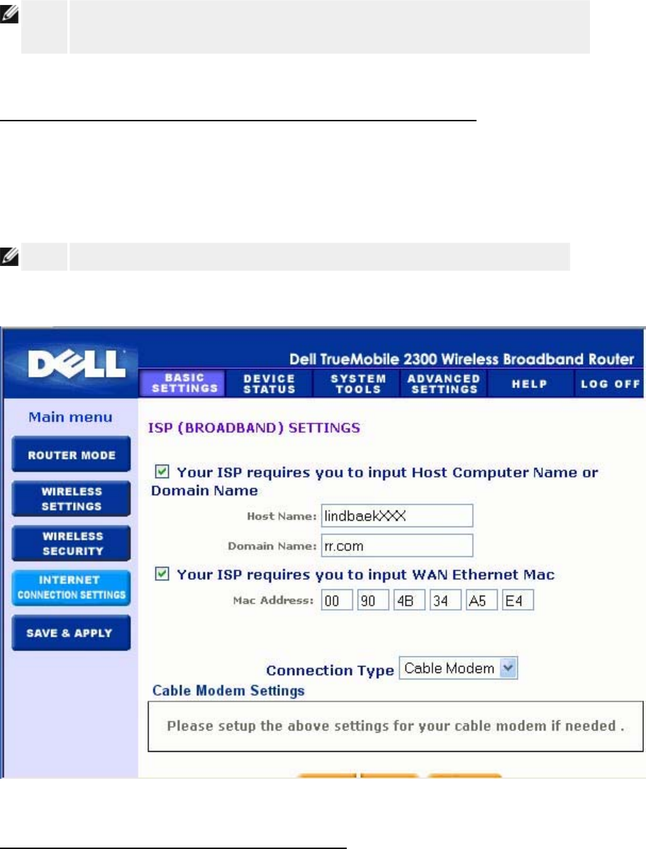
NOTE: If the device is put in AP mode, the Internet Connection Settings will not be
available.
Your ISP Requires You to Input Host Computer Name or Domain Name
If your ISP requires that you input a host computer name or domain name, click to select Your
ISP requires you to input Host Computer Name or Domain Name. Type the appropriate
values in the fields provided.
NOTE: Host computer names and domain names are only used by cable modem ISPs.
Internet Connection Settings
Your ISP Requires You to Input WAN Ethernet MAC
If your ISP requires that you input a WAN Ethernet MAC address, click to select Your ISP
requires you to input WAN Ethernet MAC. In the field provided, type the public WAN
(cable/DSL) MAC address assigned to your Router. You can find the WAN MAC address on

the back panel of the Router or on the Device Information page in the web-based configuration
tool.
Connection Type
Select the connection type from the list. Four options are available.
• Cable Modem
• DSL (Static)
• DSL (PPPoE)
• PPTP
Cable Modem Settings
No additional settings are required. Make sure that the settings listed are correct.
DSL Static IP Settings
In the fields provided, type the IP address, IP subnet mask, ISP gateway address, and Domain
Name Server (DNS) IP address provided by your ISP.
DSL PPPoE Settings
Point to Point Protocol over Ethernet (PPPoE) is a proposal specifying how a host
computer interacts with a broadband modem (for example, DSL, cable, or wireless) to access
the network. In many respects PPPoE is similar to the Dialup Networking approach. If you
have a DSL (PPPoE) Internet connection, enter the PPPoE user name and password provided
by your ISP.
PPTP Settings
The following settings should be provided to you by your ISP.
• IP Address
• Subnet Mask
• Server IP Address
• User Name
• Password

If your ISP specifies that you use PPTP (Point-to-Point Tunneling Protocol) as your connection
to the Internet, you cannot use the provided Setup Wizard to automatically set up your router.
Follow the instructions below to set up your connection manually:
1. Remove the Ethernet cable from the back of the computer you currently connect with,
and connect it to the Internet port of your Router.
2. Connect the Ethernet cable provided to any of the four LAN ports, and the other end to
your computer.
3. Configure your computer's Ethernet adapter to obtain an address automatically.
4. See Windows Help for information on how to configure your computers network
adapter.
NOTICE: If you are charged for your Internet Connection by the minute, unplug the
network cable from the Internet port on the Router when Internet access is no
longer desired.
Back to Top
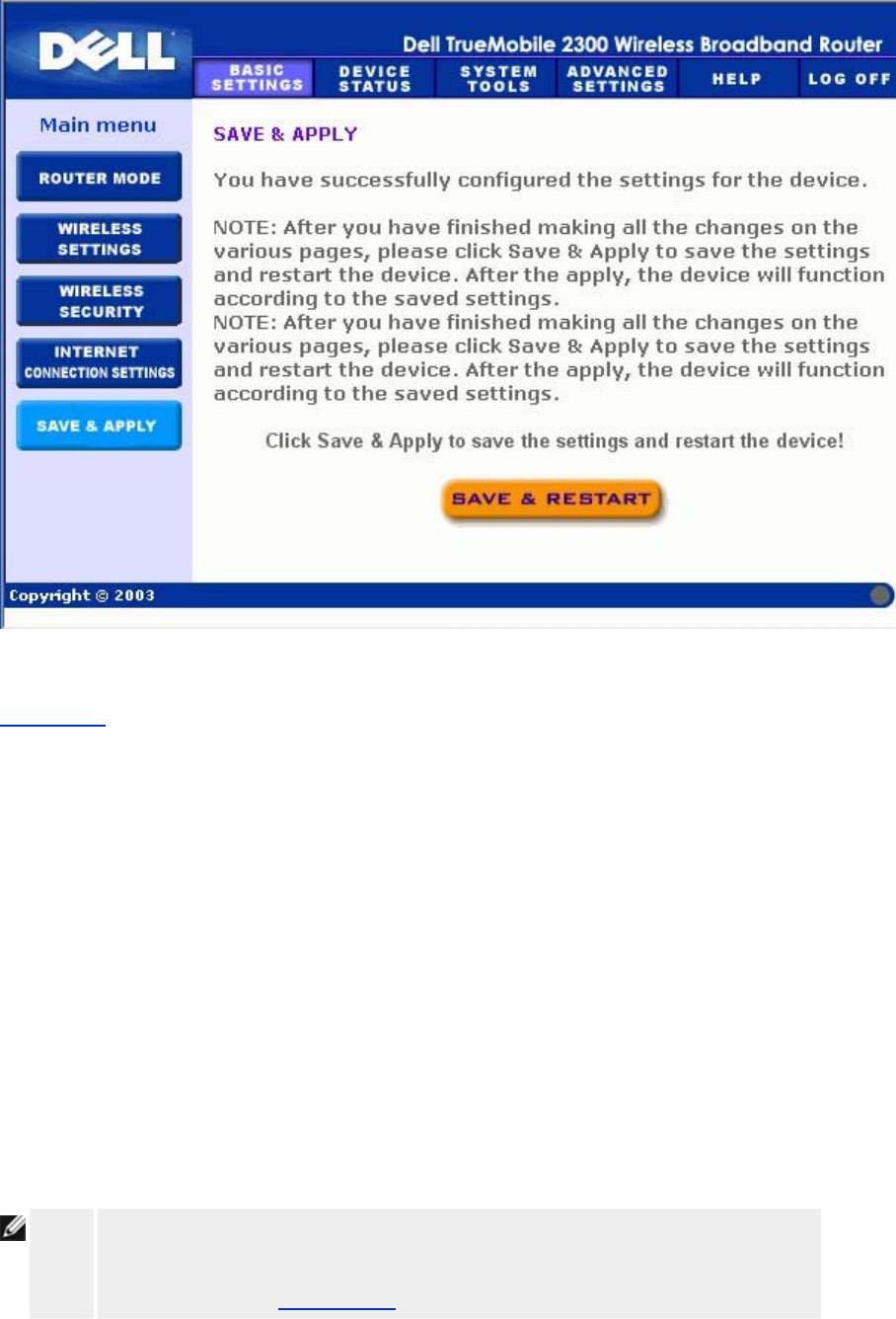
Save & Apply
Use the Save & Apply page to submit all the network setting changes you have made. Click
the Save & Restart button to update the network configurations for your Router.
New settings are written to the firmware, and the Router reboots automatically.
NOTE: If you have wireless clients in your network, you must configure the clients' wireless
network cards to match the settings for the Router.
Save and Apply
Back to Top
Device Status: Dell™ TrueMobile™ 2300
Wireless Broadband Router User's Guide
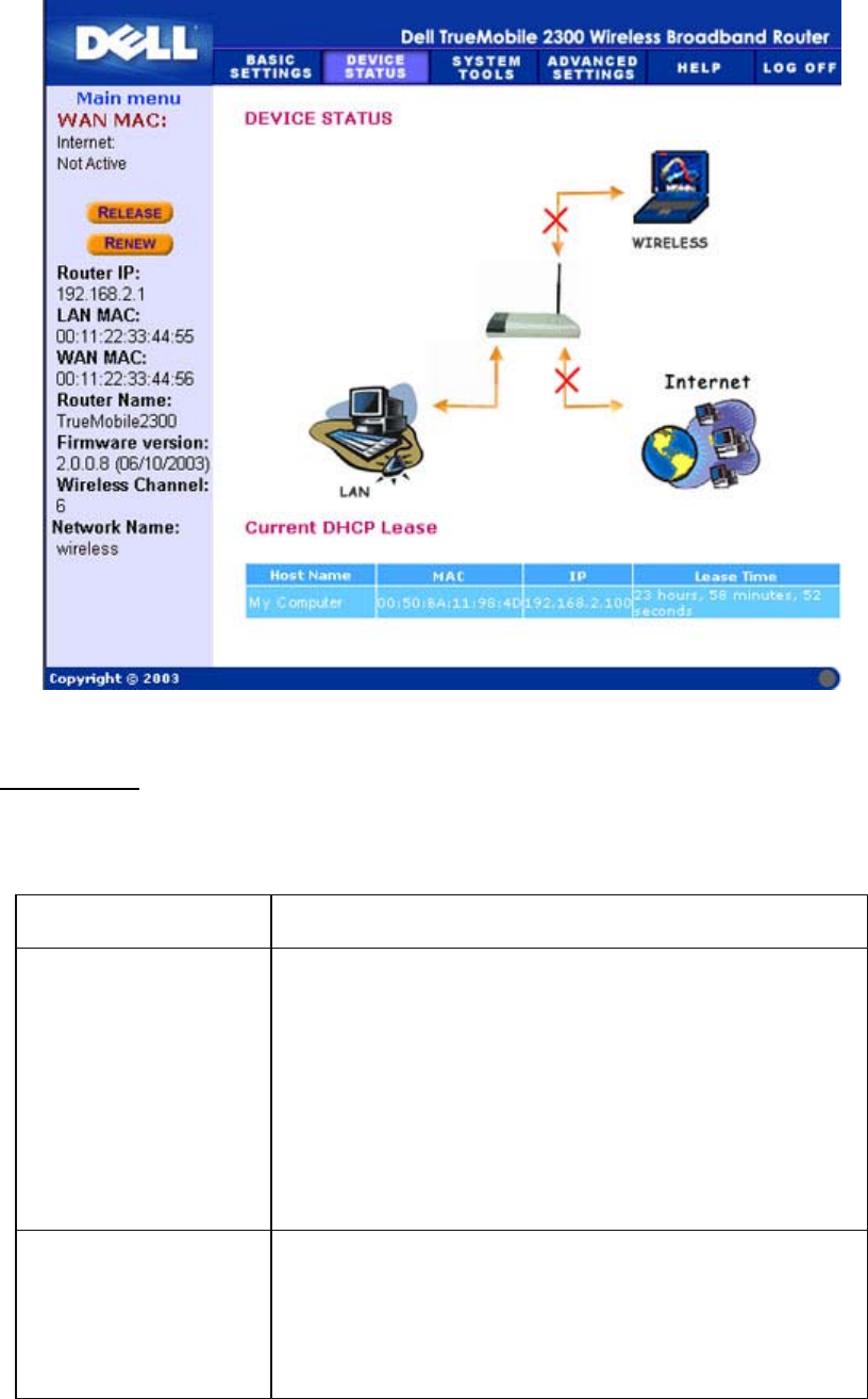
The Device Status screen displays the basic network settings for your Wireless Broadband
Router. When changes are made to the network settings, those changes are updated on this
screen. In addition, it graphically displays the current connection status for the Router and
other devices in your network. Connections between network devices are shown with a yellow
arrow. Inoperative connections are represented by one red X through the yellow connection
line.
NOTE: The router offers two ways to check the status of your network. One is the Device
Status feature in the web configuration tool mentioned here. The other is through
the Windows-based Control Utility.
Status
Device Status
The following connections are displayed on the Device Status page:
Device Indication
Internet
An inactive cable/DSL connection indicates that either the
cable is unplugged or the Router has not received an IP
address.
A
n active connection indicates the WAN interface of the router
has a valid IP address and your computers can connect to the
Internet via the router.
Wired Client (LAN)
Shown as an active connection when a wired client is
configured and physically connected to your network, and
inactive when the Ethernet cable is disconnected from the
computer.

Wireless Client
Shown as an active connection when a wireless client is
configured for your network, and inactive when there is no
wireless client connected to your router.
When the Router acts as a DHCP server, it assigns IP addresses to the clients on the network.
These IP addresses are displayed in the DHCP Log below the Device Status figure.
WAN Ethernet Settings
Refer to the left side of the screen for the following WAN Ethernet settings and the Internet
protocol (IP) settings for the Router:
Setting/Device Information Displayed
Internet The connection to the Internet is Active/Not Active
Router IP IP address assigned to the Router
LAN MAC MAC address for the LAN and Wireless interfaces
WAN MAC MAC address for the WAN interface
Router Name The name for the Router (the default is Router)
Firmware Version Version number of the firmware currently installed on the
Router and the release date of the firmware
Wireless Channel Radio channel on which the Router is communicating on the
air
Network Name
A unique network name that identifies the network. It is also
known as SSID (Service Set Identifer). When a client station
tries to connect to the router, the user must know the router's
SSID first.
The following buttons appear on the left navigation bar:
Button Action
RELEASE
Releases the IP address that the Router has been assigned
from your ISP. If the Router has been configured to receive a
static IP address, clicking Release does not release this IP
address.
RENEW Renews the IP address with a DHCP server
p
rovided b
y
y
our

ISP. If the Router has been configured to receive a static IP
address, clicking Renew does not renew the IP address.
Back to Top
System Tools: Dell™ TrueMobile™ 2300
Wireless Broadband Router User's Guide
Use the System Tools section to view the intruder detection log, routing tables, and system
diagnostics regarding the device settings and status. The System Tools section also includes
features to restore the default settings, upgrade the firmware for the Router, and reset the unit.
Use the following pages in the web-based configuration tool to access the System Tools:
Intruder Detection Log
Display Routing Table
System Diagnostic
Load Default Settings
Upgrade Firmware
Reset Device
Intruder Detection Log
Indicator Description
Event Type of attack that the router detects
Time Based on the timestamp of the IP packet, plus or minus the time offset
Source IP address that the packet came from
Dest (=Destination) Usually the IP address for the Router
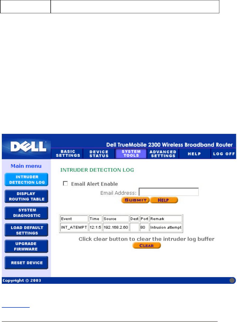
Port Port number
The system can alert you via e-mail to any attempted intrusion.
1. Click to select Email Alert Enable.
2. Type the e-mail address that you want the alert sent to in the Email Address field.
3. Click the Submit button.
The figure below shows an example of an entry of an intrusion attempt event from a computer
with IP address 192.168.2.60 (Source) targeted at the router's port number 80 at time 12 AM:1
Min: 5 Sec.
Intrusion
Back to Top
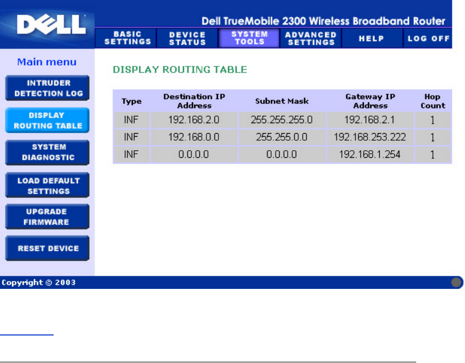
Display Routing Table

Indicator Description
Type The type of routing. This can be either of the following:
LAN or WAN interface (INTF)
Static routing
Destination LAN IP
Address
Either an entire network or a specific IP address. An IP address ending
in .0 refers to a network.
Subnet Mask Must follow the subnet mask rules
Gateway IP Address To communicate with an IP address matching the destination IP
Address, the Router sends all traffic through the gateway IP address
listed here.
Hop Count The number of routers the packet has passed through to its destination.
Hop count is used to measure the distance between a source and a
destination. If there are 3 routers between the source and the
destination nodes, the hop count for the packet will be 3 when it arrives
at its destination node.
The figure below shows three network routes that your router currently possesses.
192.168.2.0 is the destination network connected to one of your router's interface ports (LAN
or WAN) and the IP address and Subnet Mask for this interface is 192.168.2.1 and
255.255.255.0, respectively. The number of routers (Hop Count) the packet passed through is
1. Also in the same example, the destination with 0.0.0.0 network and 0.0.0.0 Subnet Mask is
the default route for your router, where every packet that left unmapped to any other route will
be mapped to this route. The outgoing default gateway IP address is 192.168.1.254.
Routing Table
Back to Top
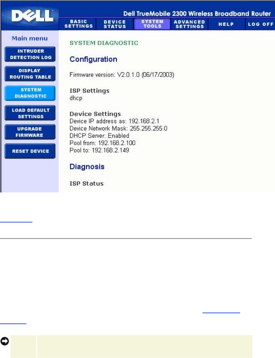
System Diagnostic
The Systems Diagnostic page is for your information only. This page displays both the
configuration settings and diagnostics for the Router. Configuration settings include firmware
version, the ISP and device settings that have been configured for your network.
The Diagnostic section shows the current connections for your network. Diagnostic settings
include the ISP status, link status, current WAN connection, LAN MAC table, and WAN MAC
table.
System Diagnostic
Back to Top
Load Default Settings
The Load Default Settings page allows you to reload the factory default configurations that
came with the device. When this option is used, the default IP address is reset to the factory
default value (192.168.2.1). This is equivalent to pressing and holding the Reset button on the
back panel of the device for more than 3 seconds (for more details, refer to A Look at the
Hardware).
NOTICE: Loading the default settings option will cause the current settings for your Router
to be lost.
Load Default Settings
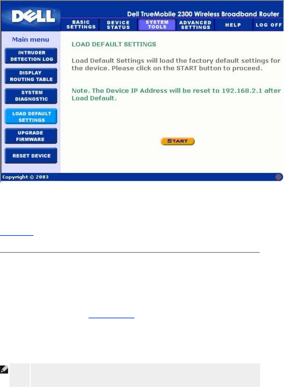
Click the Start button to reload the default settings.
Back to Top
Upgrade Firmware
Dell periodically releases firmware updates to provide improved performance or capabilities.
Use the firmware upgrade feature to easily upgrade the firmware on your Router. You can
check the Dell support website, support.dell.com, to see if there are any new upgrades.
Download the new firmware first before upgrading and save it to one of the clients in your
network. To upgrade the firmware, type the firmware file path into the box, or click the Browse
button to choose a firmware file to upgrade to.
NOTE: Make sure the file you choose is an actual Wireless Broadband Router firmware
file.
Upgrade the Firmware
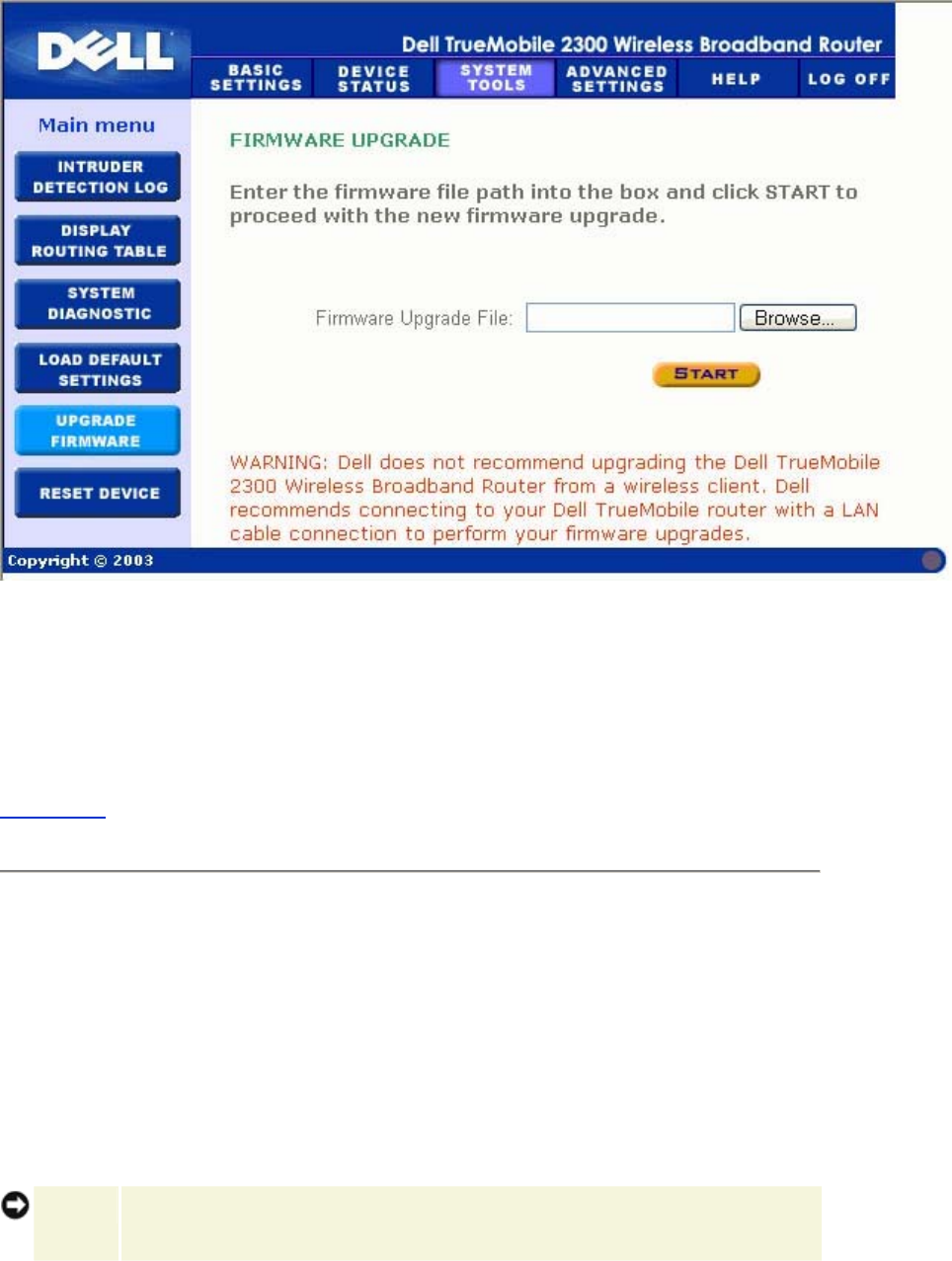
Click the Start button when you have chosen a file. After the firmware is written to the Router,
the home page will be loaded automatically. While the Router resets, the Power light on the
front panel of the router blinks.
Back to Top
Reset Device
Use the Reset Device function if a system failure occurs. This feature does not reload the
factory default settings. It simply resets the device to the network settings that existed on the
device before the system failure occurred. This is equivalent to unplugging the device and
plugging it back in or pressing the reset button for less than 3 seconds until the Power light
starts to blink. No settings are lost.
NOTICE: If you were in the process of updating the network settings, those changes are
lost when the device is reset.
Click the Start button to reset the Router to its current firmware settings. While the Router is
reset, the Power light on the front of the router blinks.
Back to Top
Advanced Settings:
Dell™ TrueMobile™ 2300 Wireless Broadband
Router User's Guide
Advanced IP Settings
DHCP Server Settings
Time Zone
Advanced Wireless
Parental Control
Access Control Settings
Port Forwarding Settings
Static Routing
Administration Settings
NOTE: Dell technical support representatives do not support the configuration options in
the Advanced Settings portion of the configuration program. These options are
provided for your convenience only. However, the advanced settings are fully
documented and explained in this guide.
The options Port Forwarding Settings and Static Routing are invisible if you are
in Access Point Mode.
After making changes to to Advanced Settings and clicking the Submit button,
click the Save & Restart button for the changes to take effect.
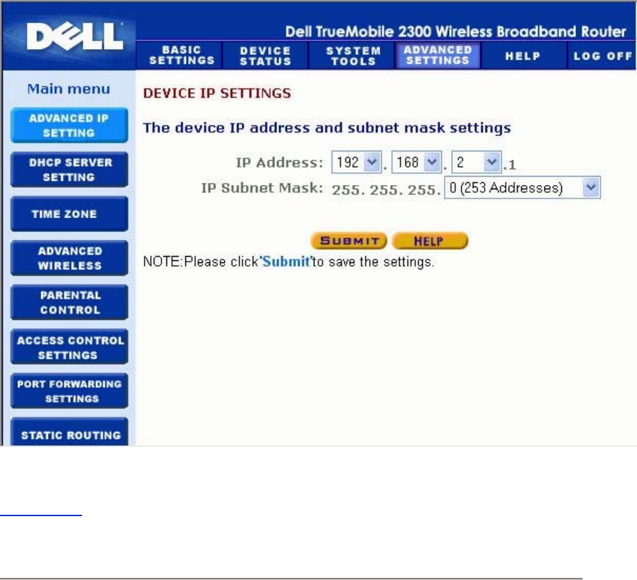
Advanced IP Settings

The Dell TrueMobilie 2300 Wireless Broadband Router comes with an assigned IP address
and IP subnet mask. These settings apply only to the local network portion of the router. If you
are installing the unit on an existing network or simply want to change these values, make sure
the IP subnet mask is the same for all devices on your network. The network portion of the IP
address must also be the same for all devices on your network.
NOTE: Dell strongly suggests you do not change the IP address unless there is a specific
reason for doing so.
While you are changing the IP address, be aware of the following:
• Changing the IP address of the Router also changes the IP address pool if the DHCP
server is enabled.
• If you are using the Router with a cable modem or DSL line, you should assign a
private IP address. Private IP addresses are in one of three ranges:
• 10.0.0.1-10.254.254.254
• 172.16.0.1-172.31.254.254
• 192.168.0.1-192.168.254.254
• You must use the new IP address to access the web-based configuration tool.
NOTE: You should only change the IP address or IP subnet mask if you are installing the
Router on an existing wired network and the DHCP server function for your Router
is disabled in the Advanced Settings. For more information, contact your network
administrator.
Advanced IP Settings
Back to Top
DHCP Server Settings
Dynamic Host Configuration Protocol (DHCP), defines a way to automatically assign IP
addresses to computers on a network. IP addresses are managed by a DHCP server. If a
Windows computer is configured to obtain an IP address automatically, it automatically gets an
address from the DHCP server.
DHCP Server Settings
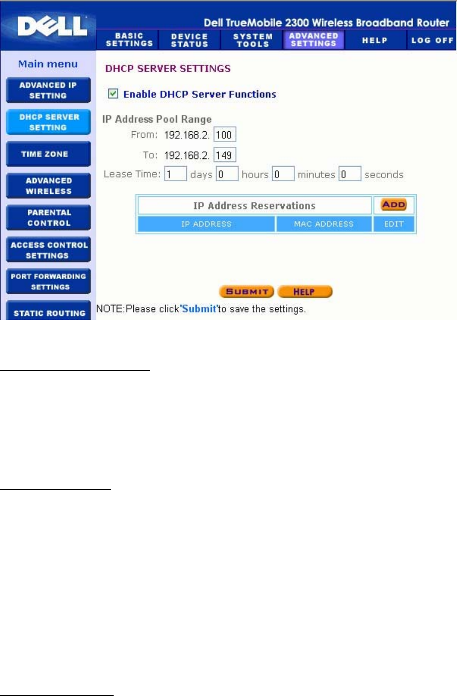
Enable DHCP Server Functions
By default, the Router is set to function as a DHCP server. If you are installing the unit on an
existing network that already has a DHCP server or simply do not want the Router to function
as the network's DHCP server, click to deselect Enable DHCP Server Functions to disable
the DHCP server function.
IP Address Pool Range
The IP Address Pool Range section provides a means of controlling a low and high value for
the IP addresses on a network. Use the indicated fields to define the range of IP addresses
you would like the Router to provide to DHCP clients. The valid range of numbers you should
enter is between 1 and 254.
The lease time is the amount of time a user will be allowed to use the IP address assigned by
the DHCP server. You may specify the lease time that DHCP server offers for the client to use
the IP address. This setting is especially useful on campuses or other environments where
users change frequently.
IP Address Reservation
Specific IP addresses may also be reserved for particular devices in a network. The IP
Address Reservation fields allow you to reserve up to four IP addresses for a specific system.
The Computer MAC field is the MAC address of the network card on the client computer. Use
the input fields under IP Address to indicate the IP address for those devices that should use
a manually defined IP address.
Back to Top
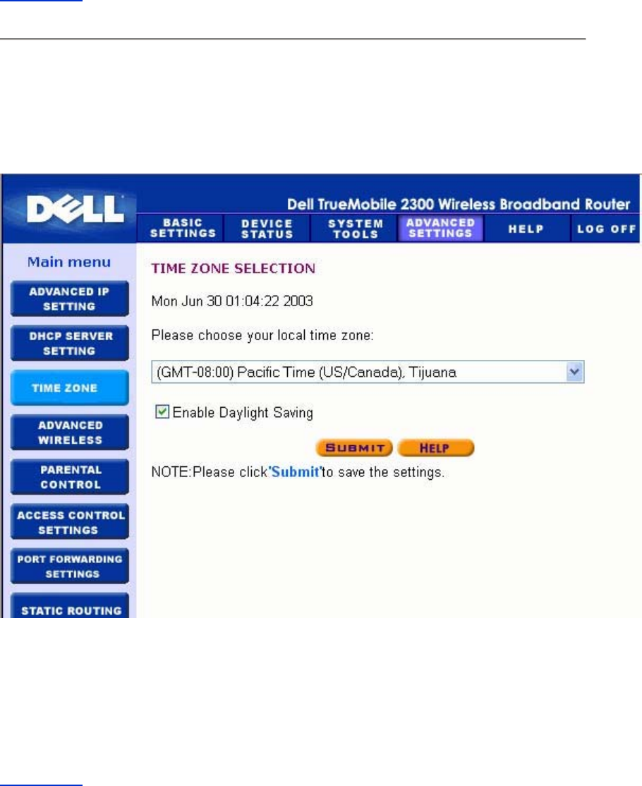
Time Zone
Time Zone
Use the Time Zone page to select your local time zone from the pull-down list. The Time Zone
Settings affect the Intruder Detection Log. This setting overrides the time stamp on IP packets
that are in Greenwich Mean Time (GMT).
Back to Top
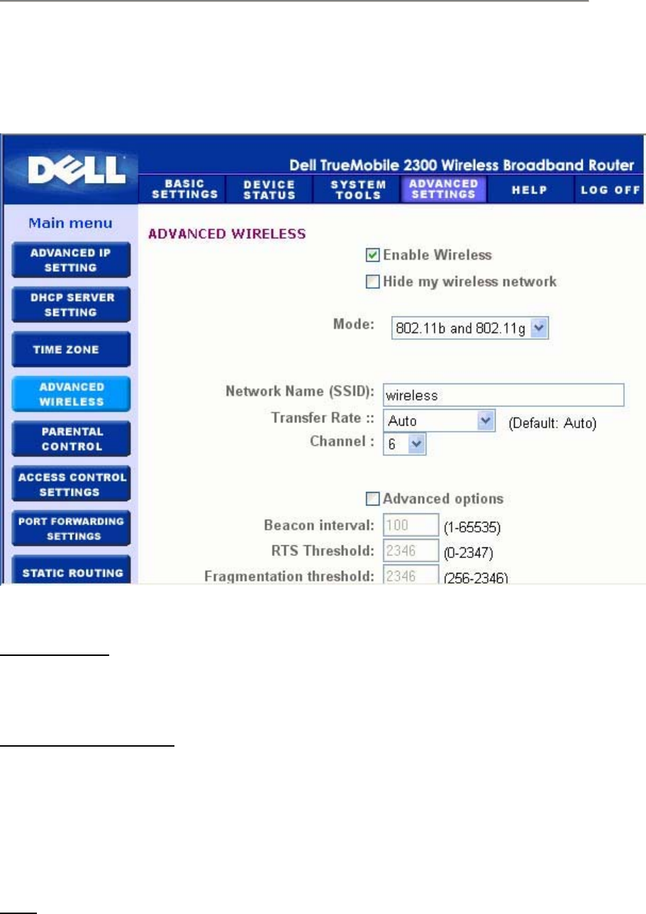
Advanced Wireless
Advanced Wireless
Enable Wireless
This setting enables radio transmission and reception on the Router.
Hide my wireless network
Checking this disables the Wireless Broadband Router to send out beacon packets to the
wireless network. It is deselected by default and other users can easily find and make
association to your Wireless Broadband Router with the use of a site survey tool.
If you want to increase wireless network security, you can enable this feature.
Mode

Router is 802.11g-compatible. You can select both b & g (dual mode), or 802.11b, or 802.11g
from the Mode list.
SSID
Service Set Identifier (SSID) is a 32-character name that uniquely identifies all the computers
and equipment that make up the wireless network.
Transfer Rate
Transfer rate can be set to automatic or some other fixed value. It is recommended that you
set the transfer rate to automatic (Auto) to allow the wireless network devices to transmit at a
rate they deem optimum at any given point of time.
Channel
The channel settings let you set the channel for this router. The radio channel is the place over
which a communication transmission occurs. The operating channel number depends on the
regulatory domain.
NOTE: If you want to configure the settings of Beacon Interval, RTS Threshold,
Fragmentation Threshold, and DTIM Interval, ensure that Advanced Options is
selected first.
Beacon Interval
The amount of time in Kusecs (one Kusec equals 1,024 microseconds) between radio
beacons from the Router to its client stations. The value range is from 1 to 65535.
RTS Threshold
The packet size above which the Router will issue a Request to Send before sending the
packet.
RTS (Request to Send) mechanism prevents the Hidden Node problem. When two stations
are within range of the same Access Point (AP) but are not within range of each other, they are
hidden nodes for each other. The packets from these two stations may collide if they arrive at
the AP at the same time. To prevent data collision with the hidden node, you can activate RTS
mechanism. If RTS mechanism is activated, the station will send a RTS first to inform the AP
that it is going to transmit the data. Then, the AP will reply with the CTS (Clear to Send) to all

stations within its range to notify all other stations and reserve the bandwidth for your data.
The RTS threshold controls what size data packet would issue a RTS. Only when the packet
exceeds the RTS threshold, the device will send a RTS before sending the packet. There is
trade-off to consider what value you should set for the RTS threshold. Small values cause RTS
to be sent more often, and it would waste the bandwidth. However, the more often RTS
packets are sent, the sooner the system can recover from collisions. It is recommended to use
the default value or only minor reductions of this default value. The value range is from 0 to
2347.
Fragmentation Threshold
The fragmentation threshold, specified in bytes, determines whether data packets will be
fragmented and at what size. Packets that are smaller than the specified fragmentation
threshold value will not be fragmented. Packets that are larger than the fragmentation
threshold will be fragmented into smaller packets and transmitted a piece at a time instead of
all at once. Thus, it will reduce the need for retransmission and improve overall network
performance. Fragmentation is activated usually when the system is in heavy traffic and
interference environment. The setting must be within the range of 256 to 2346 bytes. It is
recommended to use the default value or only minor reductions of this default value.
DTIM Interval
DTIM (Delivery Traffic Indication Message) Interval, always a multiple of the beacon period,
determines how often the beacon contains a traffic indicator map (TIM). The TIM alerts
stations in sleep state to stay awake long enough to receive their data frames. The value range
is from 1 to 255.
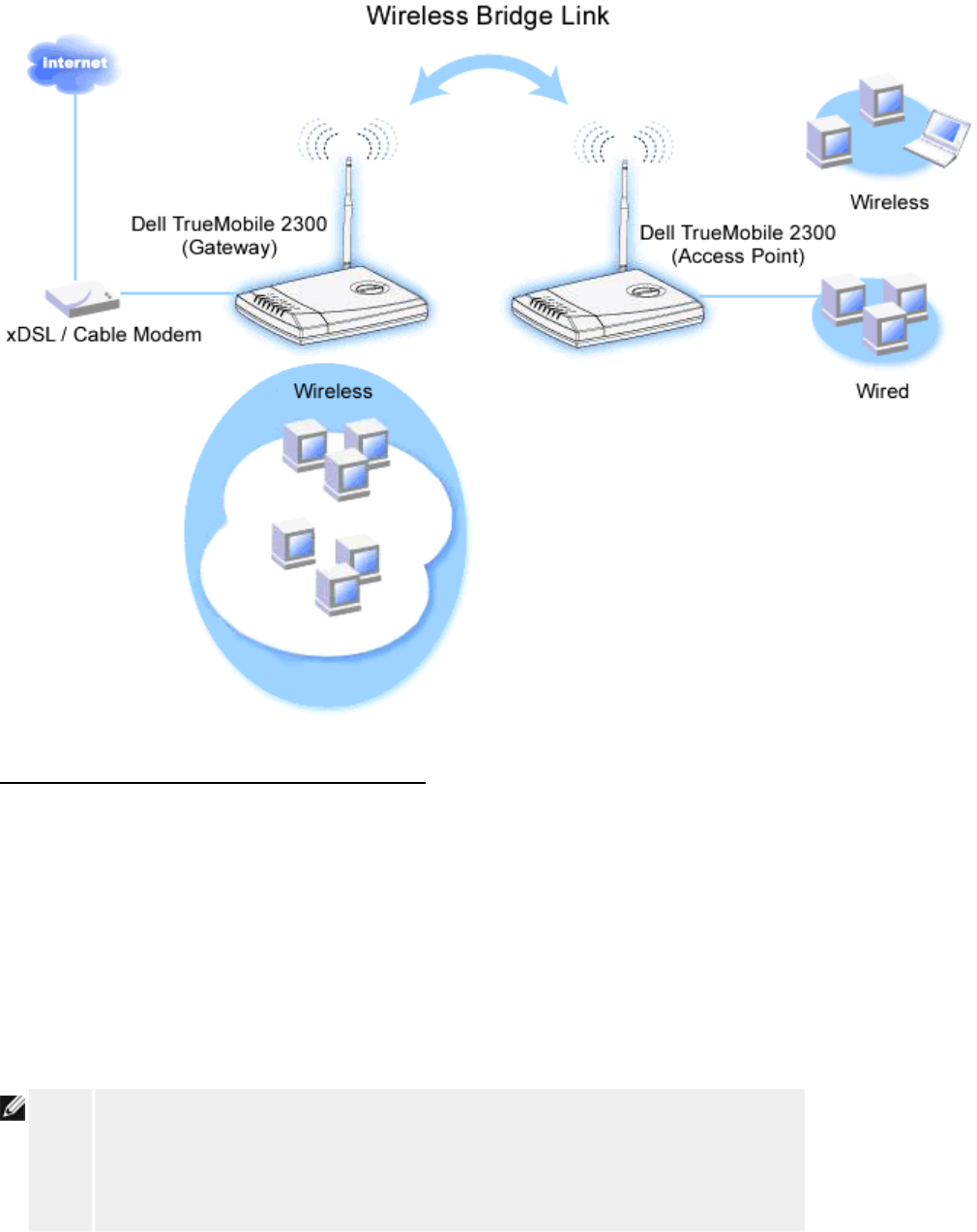
Wireless Bridge
Wireless bridging can be used to increase the coverage of your wireless network and/or to
provide wired access to remote computers. You need two or more Wireless Broadband
Routers to set up wireless bridging.
To set up wireless bridging, configure the wireless settings for all of your Wireless Broadband
Routers to the same settings.
Configuring your router for Wireless Bridging:
1. Ensure Enable Wireless is checked.
2. Type your wireless network name in the Network name (SSID) field if you want to
change it from the default setting.
3. Ensure Advanced Options is deselected.
4. Enable Wireless Bridge.
5. Type the Wireless MAC address (fields) of the other Wireless Broadband Router(s)
that you want to bridge.
NOTE: To connect two bridges together, enter the MAC address of the bridge at the other
end. To connect three bridges together, enter the MAC addresses of the other two
bridges in the bridge acted as the multipoint center. The MAC address of the center
bridge is the only address that needs to be entered into the other bridges.
6. Click the Submit button.
7. Click the Save & Restart button.
8. When your web browser returns to the main page of the Router, the device has
successfully restarted with the new settings.
9. Repeat the steps above for each Wireless Broadband router you want to bridge.
NOTE: Ensure all routers are set to same wireless settings. Also, all router(s) not directly
connected to Internet should be configured to Access Point mode.
Back to Top
Parental Control
Parental Control
IP filtering is a mechanism enabling a networking node to accept or deny certain types of IP
datagrams based on the IP address, port number, protocol type, and other criteria.
1. Click the Add button. A pop-up Parental Control Rule window will appear.
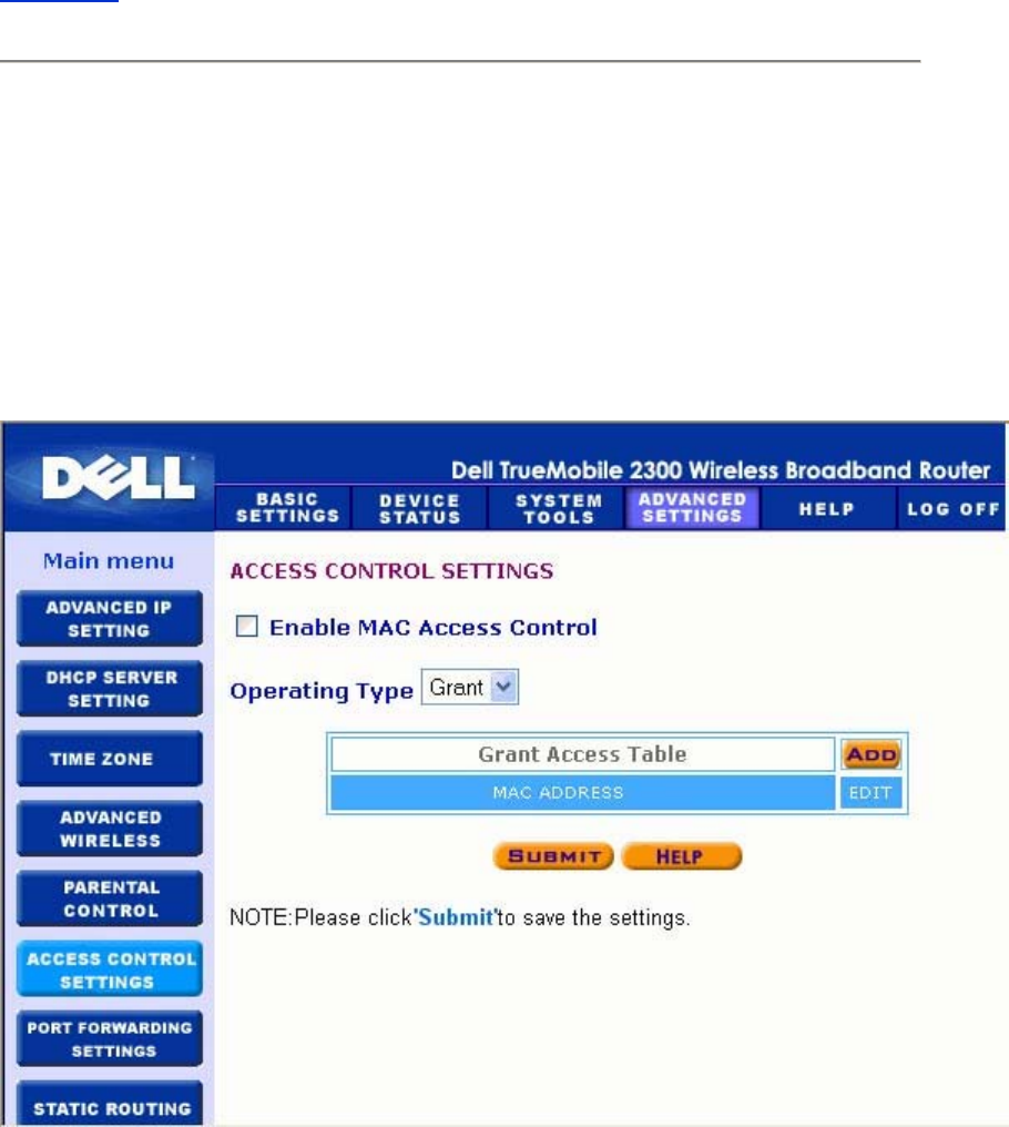
2. Click to select the IP address of the particular computer you want to control (for
example, your child's computer) in the IP Address list.
3. To block or grant access to the Internet during a period of time, specify the start and
end time from the Time Restriction list.
4. Click to select Allow or Deny from the Internet Access list.
5. Enter the URL that you want to allow or deny the access in the Web Site Restrictions
field.
6. Click to select Allow or Deny access to these web sites.
7. Click the Submit button to store the changes.
Back to Top
Access Control Settings
The Access Control Settings feature allows you to control which local client computer can
access the network through the router. The Router by default allows any local client computer
to access the network.
Access Control Settings
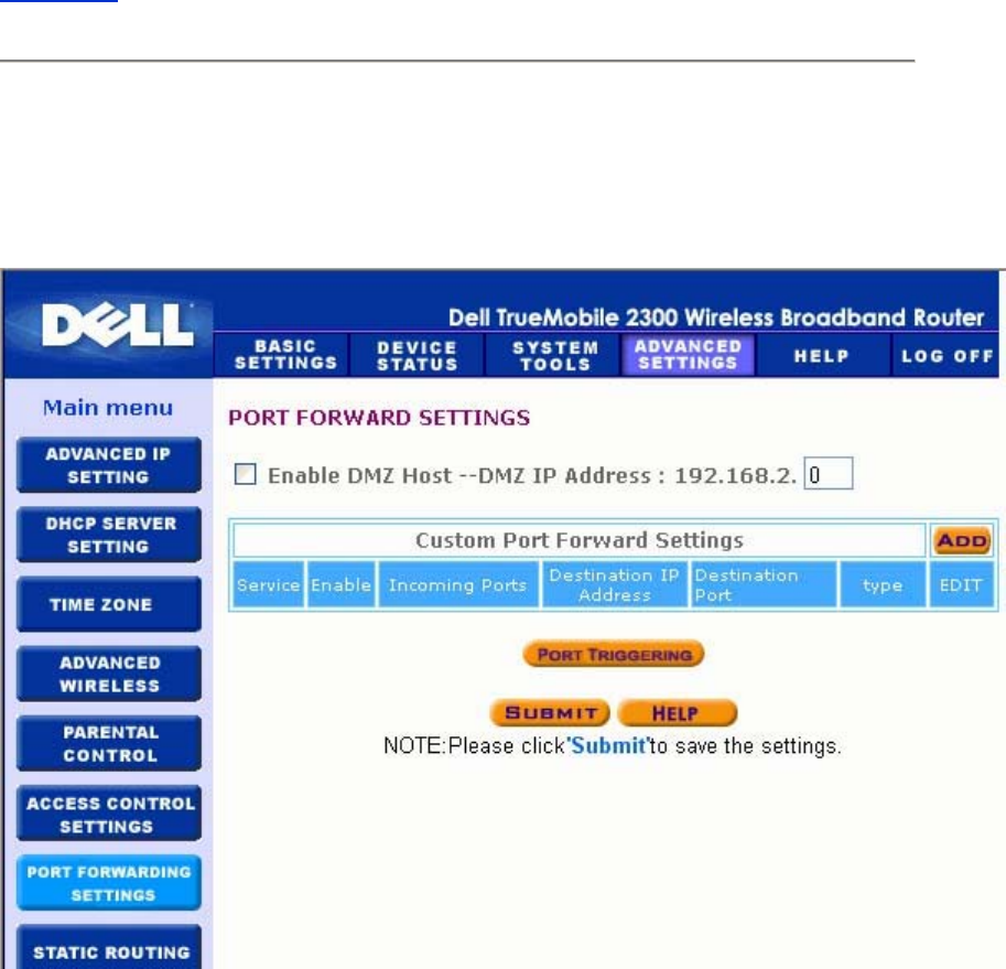
To enable access control in the router, perform the following steps:
1. Click to select Enable MAC Access Control.
2. Select the appropriate Operating Type. Grant allows client computers access to the
router. Deny restricts the access.
3. Enter the MAC address of the network card on the computer on which you wish to
apply the above control policy.
4. Click Add to enter the rule to the router.
5. To remove an existing rule, click to select Del under MAC address and click the Del
button.
6. Click the Submit button to store the changes.
Back to Top
Port Forwarding Settings
Port Forwarding Settings

DMZ
The DMZ (demilitarized zone) feature allows access to all ports. (For example, if you have
problems hosting a game server, you can choose this option. This will open all ports to your
game server.)
1. Click to select Enable DMZ Host .
2. Type the IP address of the computer that you want to run the gaming application in the
DMZ IP Address field.
3. Click the Submit button to activate the setting.
NOTE: Configuring the Router in DMZ mode is useful if you want to play certain games
through the Router, but the ports cannot be opened with all other existing
configuration tools.
NOTICE: Opening a service to the Internet causes security concerns. Pay careful
attention to security alerts, and make sure that strong access controls and
authentication are in place before allowing access to any services.
Custom Port Forwarding Settings
Port Forwarding may be more difficult than DMZ to configure. However, it provides a relatively
safe way of running an Internet application or providing an Internet service from behind a
firewall since only a single port (or a range of ports) is exposed to the Internet. You can
configure this port forwarding setting to create a custom rule that defines a specific port and
protocol for data traffic to pass through to the specific computer on your LAN.
An example is an HTTP server running on your LAN, which you want to be available to the
Internet. Your public IP address (that your ISP gives you) is X.X.X.X (The X is a number), and
you have a computer hosting the HTTP server at LAN address 192.168.2.2 on your Router
(192.168.2.1) controlled LAN. You can configure 192.168.2.2 to have port forwarding for port
80 (HTTP), then users on the Internet can go to http://X.X.X.X and get the HTTP server
(192.168.2.2). The data traffic entering service port 80 will be directed to the computer
(192.168.2.2), and other computers on your LAN will not see this data traffic.
For some Internet applications (such as Internet messaging and gaming applications), you can
configure this port forwarding setting so that these applications can function correctly behind
the firewall. These applications are required to have specific TCP/UDP ports. The ports for

these applications and the protocol type will depend on what Internet services you are using.
Check with your service provider or application's user manual to have the information first.
Make sure you have the following ports set up as described below.
1. Click to select Enable.
2. Enter the desired name or description in the Service Name field.
3. In the Incoming Ports field, enter a range of ports. If you want to specify only a single
port number, enter the same number in both fields.
4. In the Destination IP Address field, enter the IP address of the computer you want to
receive the connection request.
5. In the Destination MAC Address field, enter the MAC address of the computer you
want to receive the connection request.
6. In the Destination Port field, enter a port number or a range of ports of the machine to
which you are mapping.
7. In the Port type field, select TCP, UDP, or both protocols. The protocol could be
specified in your application's documentation.
8. Click the Submit button to activate the setting.
For example, if you want to play the game Fighter Ace II on a computer with an IP address of
192.168.2.3, enter 3 for the Destination IP Address. Find the MAC address of this computer
and enter it for the Destination MAC Address. Select TCP as the Port type. Enter 50000 and
51000 for two fields of Incoming Ports and also for the Destination Port. Click Submit
button to activate the setting. For other games or services, consult the application's user
manual.
The steps below show how to find the MAC address of the computer in Windows 2000 and XP.
1. Click the Start button, and then click Run.
2. In the Open: field, type the following text:
cmd
3. Click the OK button.
4. At the command prompt, type the following text to obtain the Physical Address(MAC
address):
ipconfig/all
Commonly Used Ports
Services Protocol Type Ports

HTTP (WEB
Server) TCP 80
FTP TCP 20, 21
TELNET TCP 23
SMTP (Mail
Server) TCP 25
POP3 (Mail
Server) TCP 110
IRC TCP 6667
NNTP (News
Server) TCP 119
Port Triggering
Port triggering allows the router to watch outgoing data for a specific port number. The IP
address of the computer that sends the data is remembered by the router, so that when the
requested data returns through the router, the data will be passed to the specific computer by
way of IP address and port mapping rules. The router opens the port when the Port Triggering
happens. When the computer running the application stops sending the data through this port,
the router will close the port.
1. click to selectEnable.
2. Enter the desired name or description in the Application Name field.
3. In the Trigger Port field, enter a port number. Check with your Internet application
provider for more information on what Trigger Port it is using.
4. Select TCP (Transmission Control Protocol), or UDP (User Datagram Protocol), or
both protocols as the Trigger Port Type.
5. Specify the range of the Public Ports by typing the start and end port numbers in the
required fields.
6. Select TCP (Transmission Control Protocol), or UDP (User Datagram Protocol), or
both (TCP and UDP) as the Public Port Type.
7. Click the Submit button to activate the setting.
Click the Submit button to store the changes.
Back to Top
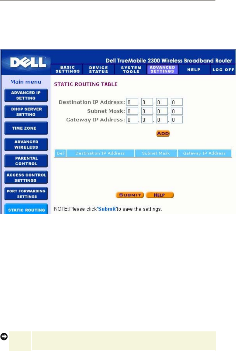
Static Routing
Static Routing
Static routes are manually configured routes to remote networks. That is, the route is
predefined and is not discovered by the Routing Information Protocol (RIP), as in dynamic
routing. Static routing allows you to assign a gateway to an IP address or network. If there are
routers on your internal network that do not function with RIP 1 or 2, you can set up a static
route to those routers.
The advantage to using static routing is that network traffic is reduced; thus, static routing is
beneficial for slow Internet connections. Routing using static routes is practical for small
networks. For larger networks, the router needs to dynamically keep track of changes in the
physical wiring of the network, and the use of dynamic routing (RIP) is recommended.
NOTICE: The Static Routing settings are intended for advanced network administrators
only. Do not change these settings unless you are certain of the correct values.
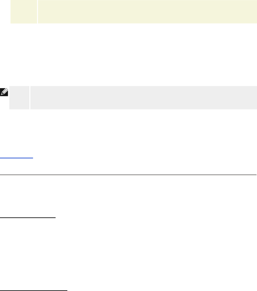
You may not be able to access the configuration tool if invalid information is
entered.
To use static routing, manually add the Destination IP Address, Subnet Mask, and Gateway IP
Address for each route you are adding to the Static Routing Table, and click Add. If you are
routing to an entire network, the last number in the destination IP address should be a zero (0);
for example, 192.168.0.0.
NOTE: In static routing, the Router does NOT dynamically discover routing information and
does NOT use RIP. The Router currently does NOT support RIP.
Use the fields beside each route and the Delete button to remove static routes from the Static
Routing Table.
Back to Top
Administration Settings
Password Settings
The Router uses a password to authenticate the user before allowing changes to be made to
any network settings. If you would like to change the current password, click to select Change
Your Password and enter the new password in both New Password and Retype Password
fields. Write down the password and keep it in a secure location for future reference.
System Administration
• HTTP Port No.
Do not change the HTTP Port value unless you have reason to do so. Typically, web
servers listen for incoming web requests on port 80.
• Allow remote user to configure the device
If you would like a remote user to be able to administer your Router over the Internet,
click to select titled Allow remote user to configure the device. Enter the IP address
for the remote administration host computer.
• Allow remote user to ping the device
Click to select Allow remote user to ping the device to enable your Router to be
pinged by any user on the Internet. This feature is helpful if you want to let other
Internet users to click to select the status of your Router.
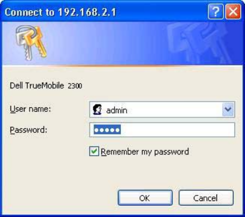
• Enable UPnP function UPnP stands for Universal Plug and Play, a protocol which
allows UPnP-enabled client computers, such as Windows XP, to discover and
configure the Router. One of most common use of UPnP on the router is to open ports
to allow application-specific data to be forwarded through the router for various
Internet services or gaming applications. The router detection and the router
configuration process can be carried out automatically by the UPnP-enabled client
applications such as MSN Messenger so you won't have to do it manually. Click to
select Enable UPnP function to enable this service.
If you have an Windows XP system, you can use it to access and control the router
while the router's UPnP function is enabled. Here are some examples of what you can
do with UPnP from your Windows XP system.
Example 1: Access the router's web configuration tool without knowing its IP address.
1. Double-click the My Network Neighborhood icon from the desktop.
2. Double-click the Broadband Router icon that is created for your router.
This will bring up the authentication screen of the router's Web configuration
tool.
3. Type the correct password and click the OK button to access the web
configuration tool.
Authentication Screen
Example 2: Manage the router's port forwarding rules from the Windows XP interface.
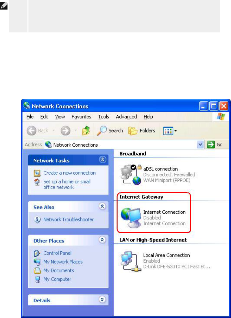
NOTE: If you have already configured a port forwarding rule for the service
through the web configuration tool, you don't need to perform the following
steps for the same service again.
4. Right-click the My Network Neighborhood icon on the desktop.
5. Right-click the Internet Connection icon created for the router.
Network Connections
6. Right-click the icon and left-click Properties.
7. Click Settings.
8. Click Add.
9. Type Description of service, IP address of the service host, External Port
number for this service, Internal Port number for this service, and click to
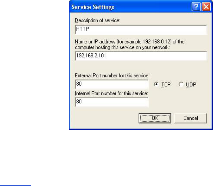
select either TCP or UDP. For example, the graph below shows an example of
how to enable a computer with an IP address 192.168.2.101 to host a public
HTTP server.
Service Settings
10. Click the OK button to save the changes.
Back to Top