GemTek Technology R950829G High Performance Hotspot Access Point User Manual BW1330 UG v1 0
Gemtek Technology Co., Ltd. High Performance Hotspot Access Point BW1330 UG v1 0
Contents
- 1. Manual Part 1
- 2. Manual Part 2
- 3. Manual Part 3
Manual Part 2
User’s Guide Version 1.0
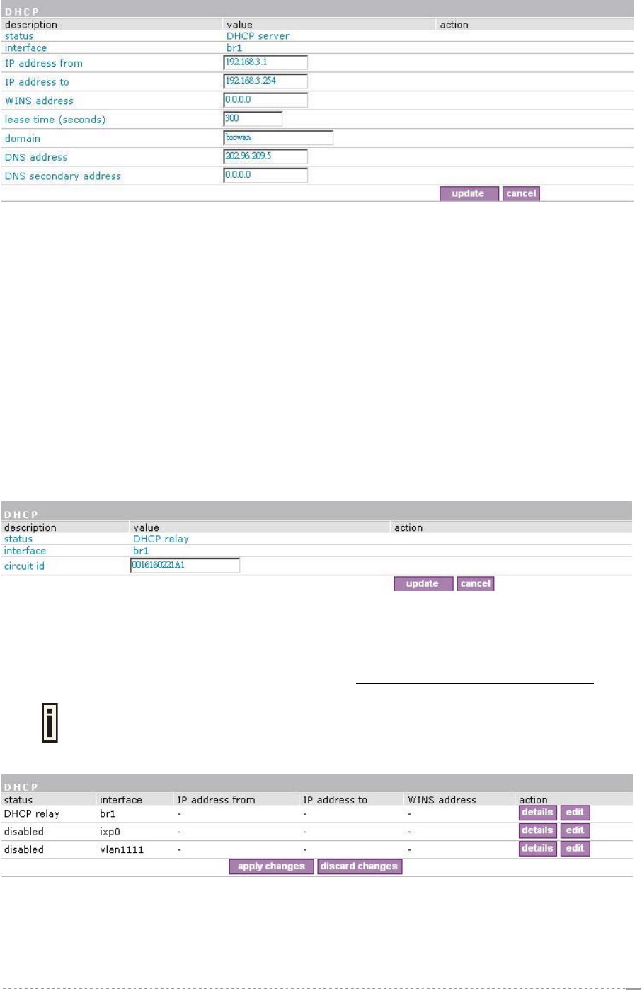
Figure 103 – Edit DHCP Server Settings
IP Address from/IP Address to – specify the IP address range supported for the DHCP service
[mandatory fields].
WINS Address (Windows Internet Naming Service) – specify service IP address if it is available on
the network [dots and digits].
Lease Time – specify the IP address renewal in seconds [1-1000000].
Domain – specify DHCP domain name [optional, 1-128 sting].
DNS address – specify the DNS server’s IP address [in digits and dots notation].
DNS secondary address – specify the secondary DNS server’s IP address [in digits and dots
notation].
Case 2 Configure the DHCP relay
Select the interface on which you want to configure the DHCP service. Select the DHCP relay and
click the update button specify the DHCP relay parameters:
Figure 104 – Edit DHCP Relay Settings
Circuit ID – the unique DHCP relay parameter [optional, by default the MAC address of the device
WAN interface is used].
If want designate the DHCP relay server, please refer to network configuration | DHCP relay.
If DHCP relay service is selected, the default WAN gateway is used automatically.
Update – to update entered values, the following screen appears:
Figure 105 – Apply or Discard DHCP Server Settings
Apply Changes – to save entered new DHCP settings.
Discard Changes – to restore previous values.
BROWAN Page
69
User’s Guide Version 1.0
Network Interface | POP3
It is convenient to use POP3 authentication way if there has no RADIUS server. BW1330 use POP3
interface to authenticate clients instead of RADIUS protocol.
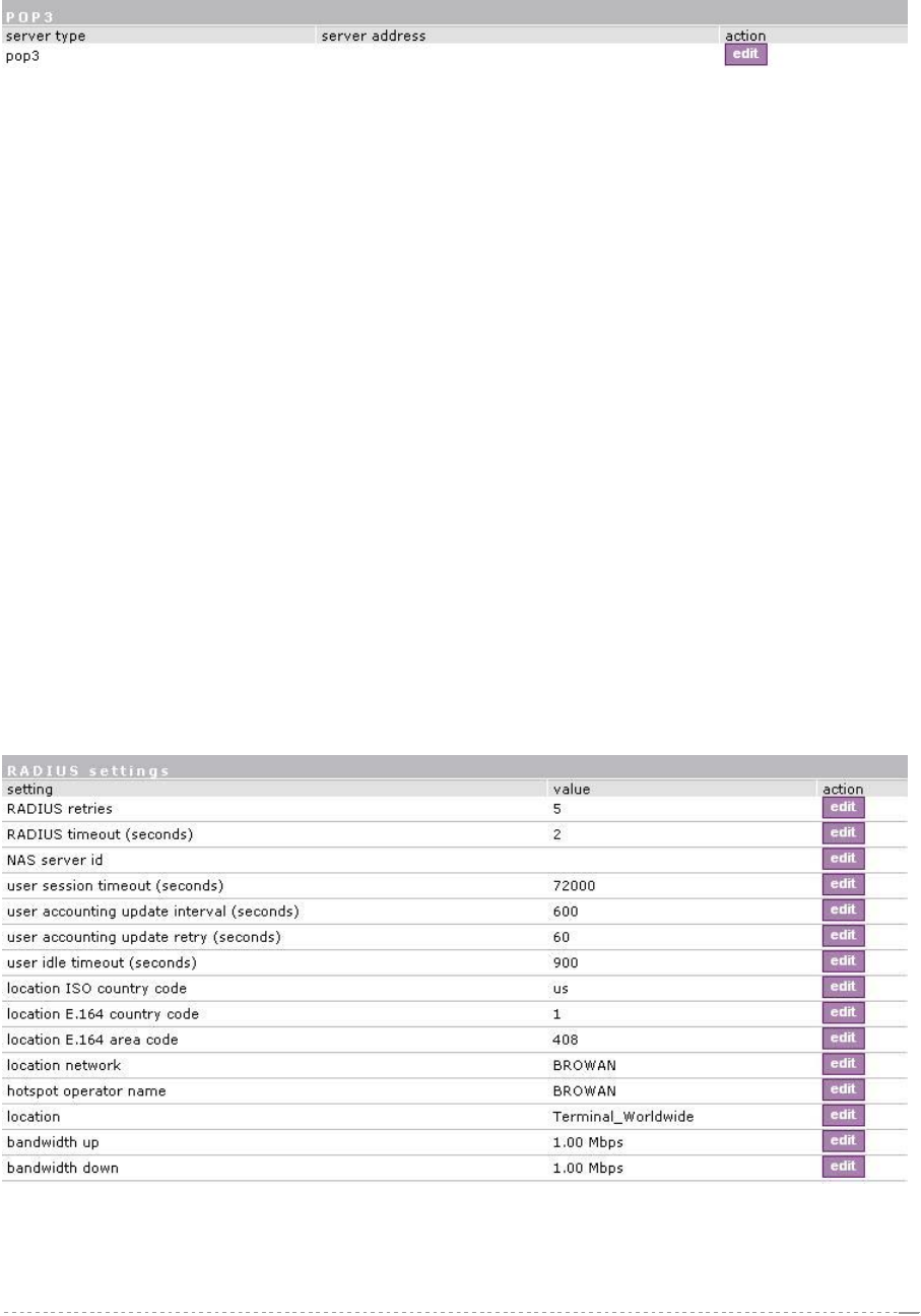
Figure 106 – POP3 Server configuration
Just fill out the POP3 server IP address or URL name such like “mail.browan.com”.
Network Interface | RADIUS
RADIUS is an authentication and accounting system used by many Internet Service Providers (ISP).
RADIUS enables ISPs to maintain a very large database of users. By using RADIUS, service
providers can implement policy-based management of their subscribers’ base. RADIUS also helps
ISPs to collect statistical data about their subscribers (e.g. amount of time, amount of transferred
bytes, and session time).
Use the RADIUS (Remote Authentication Dial In User Service) menu to set-up the following RADIUS
settings:
RADIUS Settings – general RADIUS settings configuration (e.g. NAS server ID, servers timeouts)
RADIUS Servers – up to 32 different RADIUS servers’ configuration (accounting and
authentication servers)
WISP (Wireless Internet Service Provider) – specify WISP domain for RADIUS server
Proxy – configure the BW1330 to act as RADIUS proxy server.
Accounting Backup – backup the RADIUS subscribers accounting information.
Network Interface | RADIUS | Settings
General RADIUS settings are configured using the RADIUS settings menu under the network
interface:
Figure 107 – RADIUS Settings Configuration
RADIUS Retries – retry count of sending RADIUS packets before giving up.
RADIUS Timeout – maximum amount of time before retrying RADIUS packets [sec].
BROWAN Page
70
User’s Guide Version 1.0
NAS Server ID – name of the RADIUS client.
User Session Timeout - amount of time from the user side (no network carrier) before closing the
connection [sec].
User Accounting Update - period after which server should update accounting information [sec].
User Accounting Update Retry – retry time period in which server should try to update accounting
information before giving up [sec].
User Idle Timeout - amount of user inactivity time, before automatically disconnecting user from the
network [sec].
Location ISO Country code – location ID attribute, country code according ISO standards [string].
Location E.164 Country code – location ID attribute, country code according E.164 specification.
Location E.164 Area code – location ID attribute, area code according E.164 specification.
See the Location ID and ISO Country codes for your country in the Appendix: D)
Location ID and ISO Country Codes.
Location Network – location ID attribute, network name [string].
Hotspot Operator Name – location name attribute, operator’s name [string].
Location – location name attribute, textual description of the location [string].
Bandwidth Up – maximum bandwidth up at which corresponding user is allowed to transmit [bps].
Bandwidth Down – maximum bandwidth down at which corresponding user is allowed to receive
[bps].
User can check its available bandwidth in the logout page statistics.
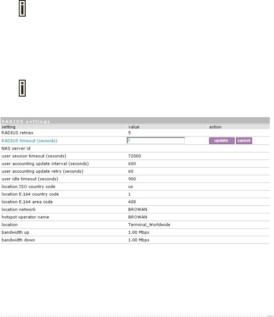
Each setting in this table can be edited. Select RADIUS setting you need to update, click the edit next
to the selected setting and change the value:
Figure 108 – Edit RADIUS Settings
Use the update button to update to an entered value. Now select another RADIUS setting to edit, or
apply changes and restart the server if the server configuration is finished:
BROWAN Page
71
User’s Guide Version 1.0
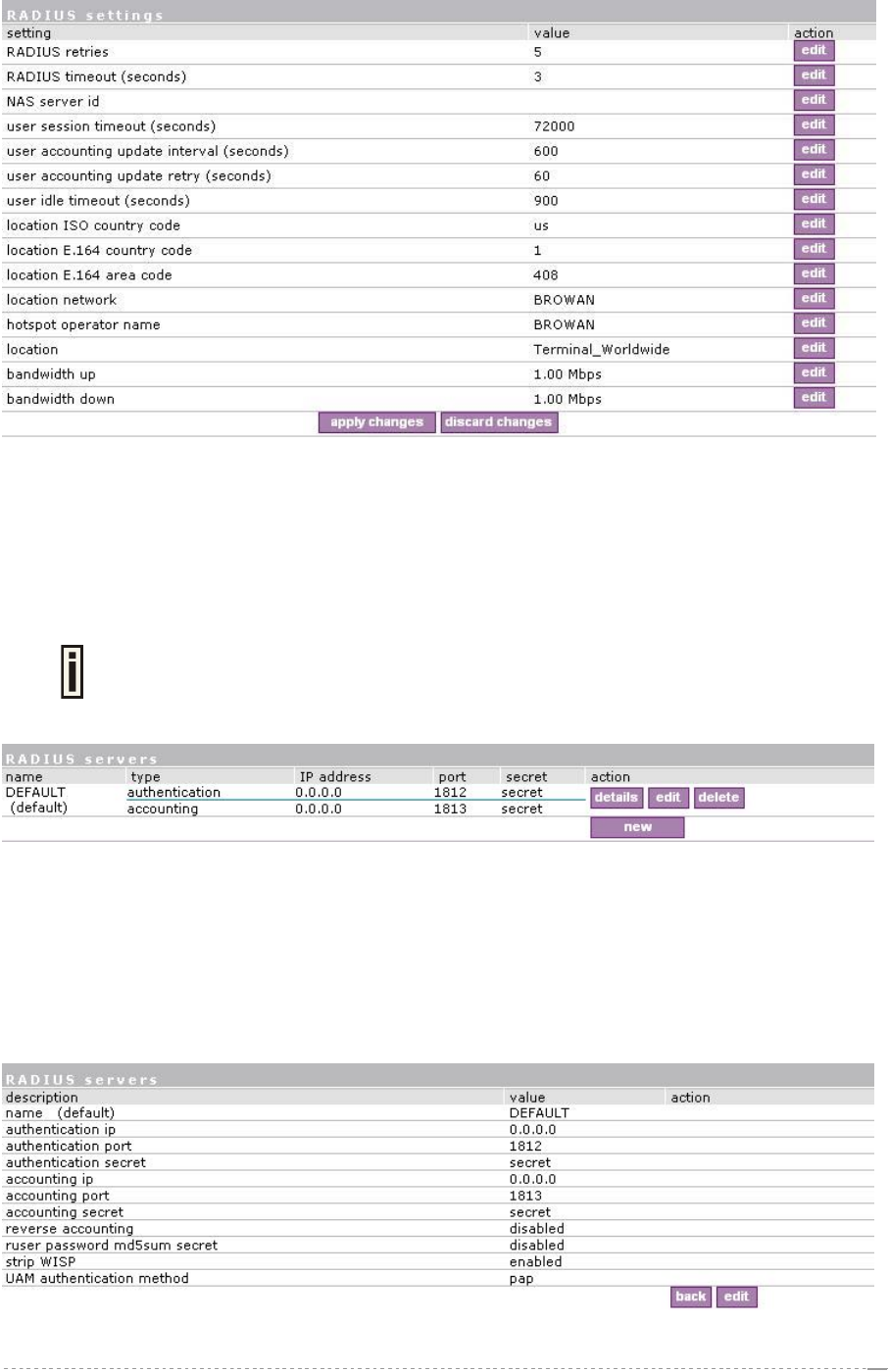
Figure 109 – Apply or Discard RADIUS Settings
Apply Changes – click if RADIUS settings configuration is finished.
Discard Changes – restore all previous values.
Network Interface | RADIUS | Servers
Up to 32 different RADIUS servers can be configured under the RADIUS servers
menu.
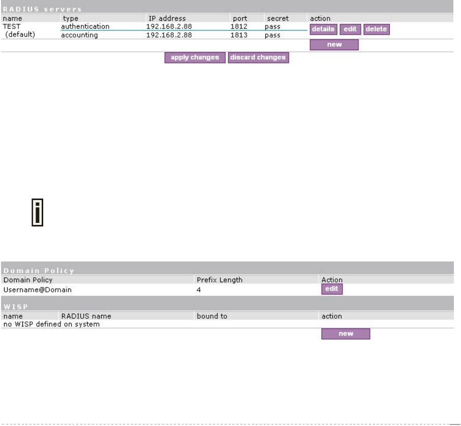
By default, one RADIUS server is specified for the system:
Figure 110 – RADIUS Servers Settings
New – add new RADIUS server.
Details – click on details to get more information about RADIUS server settings.
Edit – edit selected RADIUS server settings.
Delete – remove selected RADIUS server.
To view complete RADIUS server settings, click the details button in the action column:
Figure 111 – RADIUS Server's Details
BROWAN Page
72
User’s Guide Version 1.0
To edit RADIUS server click the edit button:
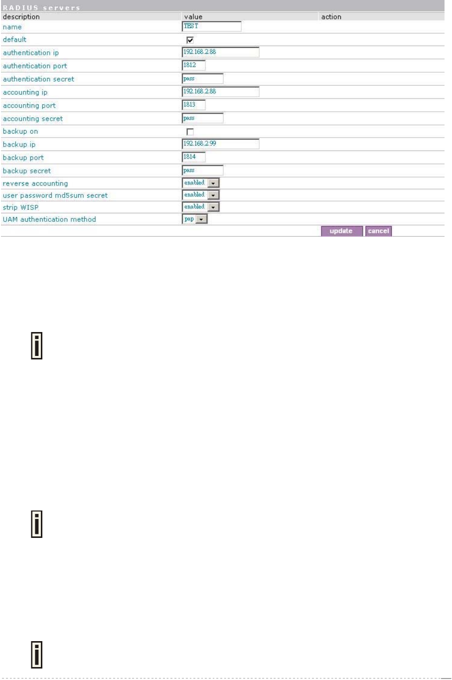
Figure 112 – Add New RADIUS Server
Name – specify the new RADIUS server name.
Default – check the check box to make the selected RADIUS the default server.
Authentication IP – authentication RADIUS server IP address [dots and digits].
Authentication Port – specify the network port used to communicate with RADIUS [1-65535].
The port default value of 1812 is based on RFC 2138 "Remote Authentication Dial-
in User Service (RADIUS)".
Authentication Secret – shared secret string that is used to encrypt data frames used for
authentication server.
Accounting IP – accounting RADIUS server IP address [dots and digits].
Accounting Port – specify the network port used to communicate with RADIUS [1-65535].
Accounting Secret – shared secret string that is used to encrypt data frames used for accounting
server.
Backup IP – backup RADIUS server IP address [dots and digits].
Backup Port – specify the network port used to communicate with RADIUS [1-65535].
Backup Secret – shared secret string that is used to encrypt data frames used for backup server.
Shared secret must be the same on RADIUS server and RADIUS client.
Reverse Accounting – [enabled/disabled]. The RADIUS accounting request contains Acc-Input-
Octets and Acc-Output-Octets attributes. The interpretation of these attributes according the
RFC2866 is relative to the point of view. If this point is at the AC - Acct-Input* attributes should contain
the bytes/packets received at AC port from the client and Acct-Output* attributes should contain
bytes/packets sent from AC port to the client. If we move this point to the client - we will get the
reversing of Acct-Input* and Acct-Output* attributes values. The Acct-Input* then should contain
bytes/packets received from AC, what is bytes/packets that AC sent to the user in AC point of view
and what was Acct-Output*.
The AC implementation of RADIUS accounting request is at the client point of view
(reverse accounting is disabled).
BROWAN Page
73
User’s Guide Version 1.0
The value "disabled" means that Acct-Input* RADIUS attributes will contain bytes/packets sent to
the client and Acct-Output* RADIUS attributes will contain bytes/packets received from the client
during the curse of service being provided.
The value "enabled" means that info in the Acct-Input* and Acct-Output* RADIUS attributes will be
swapped (reversed). That is the Acct-Input* will contain bytes/packets received from the client and the
Acct-Output* will contain bytes/packets sent to the client.
User password md5sum secret: if enabled, user input password will be md5-summerized before
pass to RADIUS server for more security (Need RADIUS Server do relevant configurations).
Strip WISP – [enabled/disabled] select ‘enabled' if you want to strip WISP domain name before
sending it to the RADIUS server. Stripping means removing everything before the “/” character
including character itself for such user name login format like: “WISPdomain/username”.
Select “disabled” if you need to send the user login name to RADIUS server unmodified. Some
RADIUS servers can be configured in such way that requires full-unmodified user name to be sent.
UAM authentication method – select authentication method from drop-down menu:
PAP – Password Authentication Protocol
Update – add new specified RADIUS server.
Cancel – restore all previous values.
After adding a new RADIUS server or editing an existing one, the following controls appears:
figure – 113 apply and reboot
Apply Changes – save changed configuration.
Discard Changes – discard all changes.
Restart – after applying changes to the system, you should restart the controller to make applied
changes work.
Network Interface | RADIUS | WISP
Up to 32 WISP entries can be defined using the network interface | RADIUS |
WISP menu.
Different WISPs (Wireless Internet Service Providers) can be associated with appropriate RADIUS
servers and device interfaces using the network interface | RADIUS | WISP menu:
Figure 114 – WISP Menu
Domain policy means BW1330 use which policy to fetch WISP name from user name then to judge
user belong which domain.
Hotspot owner can use three policy to judge the WISP name from user name:
BROWAN Page
74
User’s Guide Version 1.0
1. username follow the format: username@WISPdomain
2. username follow the format: WISPdomain/username
3. use prefix of username as wisp name, the range of prefix length is from 2 to 6.
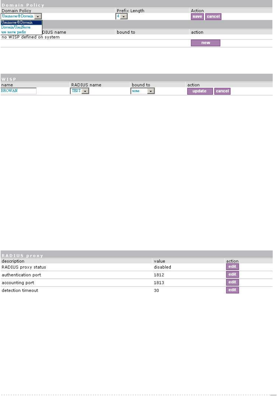
Figure 115 – Domain Policy
New – click to define WISP for RADIUS server.
Figure 116 – Define New WISP
Name – new WISP domain name [string, up to 256 symbols, no space, dot or dash allowed].
RADIUS Name – select RADIUS for new WISP from list box [non editable].
Bound To – select the WISP binder interface. The WISP can be associated with appropriate device
interface.
Update – system with new WISP.
Cancel – restore all previous values.
Network Interface | RADIUS | Proxy
The BW1330 can forward the RADIUS authentication and accounting requests from Access Point (AP)
to the real RADIUS server. To configure the RADIUS proxy, follow the steps:
Step 1 Connect the Access Point to any LAN port available on the Access Controller
(BW1330). The AP should be in the bridge mode.
Step 2 Using the network interface | RADIUS | proxy menu configure the RADIUS proxy
parameters: RADIUS authentication port (UDP), RADIUS accounting port (UDP) -
different from authentication port and Accounting detection timeout:
Figure 117 – RADIUS Proxy Settings
RADIUS Proxy Status – select [enabled] to enable the RADIUS proxy feature [enabled/disabled].
Authentication Port – specify the port on AC for listening the RADIUS authentication packets. The
AC RADIUS proxy authentication port will accept only RADIUS authentication packets [1-65535,
default: 1812].
Accounting Port – specify the port on AC for listening the RADIUS accounting packets. The AC
RADIUS proxy accounting port will accept only RADIUS accounting packets [1-65535, default: 1813].
Detection Timeout – specify the RADIUS proxy accounting detection timeout in seconds. The AC will
wait the specified period for accounting packet after the authentication request was got [0-3600].
BROWAN Page
75
User’s Guide Version 1.0
The authentication RADIUS proxy port should differ from the accounting port.
Step 3 Configure the AP to send the RADIUS authentication and accounting packets to the
AC LAN IP address and UDP ports which are configured on AC RADIUS proxy configuration.
Step 4 The RADIUS secrets on AC should be set to value, which is good at the real RADIUS
server for which the following packet will be forwarded.
Such preconfigured AC will act as RADIUS proxy and will forward the RADIUS authentication and
accounting packets from AP according WISP and RADIUS server settings in the AC configuration
without any modification.
Network Interface | RADIUS | Accounting Backup
The administrator can backup the hotspot subscribers’ RADIUS accounting information in two ways:
Via syslog protocol to the specified host
Download to the selected location (e.g. on your PC)
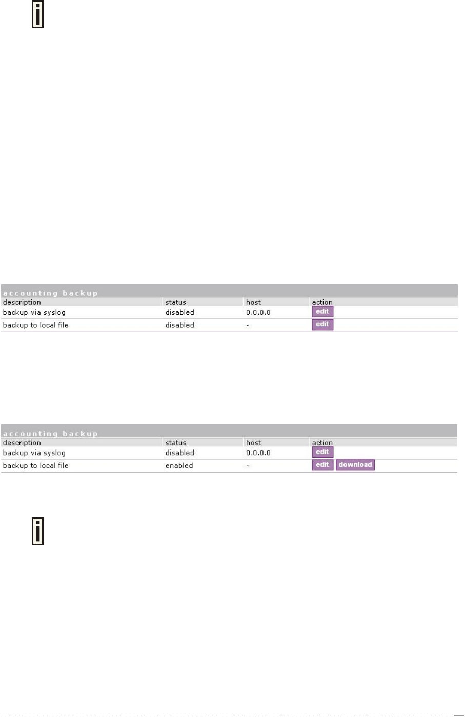
Use the network interface | RADIUS | accounting backup menu:
Figure 118 – Accounting Backup
Backup via syslog – enable this type to send the RADIUS accounting information via syslog protocol
to the specified host [enable/disable] and note that the Host IP specification is obligatory.
Host – enter host IP address where to send accounting backup messages.
Backup to local file – enable this option, and the download button appears:
Figure 119 – Accounting Backup enable
Download – click the button to download the accounting information file to your selected location.
Both types of accounting backup can be enabled.
BROWAN Page
76
User’s Guide Version 1.0
Network Interface | Tunnels
This chapter describes the configuration of VPN tunnels. VPN tunnels can be used to secure
management and AAA traffic between the hotspot network and the network operation center of the
operator.
The Access Controllers support GRE tunnels. Furthermore PPP (Point-to-Point Protocol) can be use
to authenticate the AC to a authentication server and to assign IP settings to the WAN port of the AC.
Network Interface | Tunnels | PPPoE/GRE
Use the network interface | tunnels | PPPoE/ GRE menu to connect to ISP via PPPoE or GRE
tunnel. All traffic will be sent via this tunnel.
Default gateway specified in network interface | configuration page will not be used, because all
Internet traffic will be sent/received via the specified PPPoE or GRE server (tunnel).
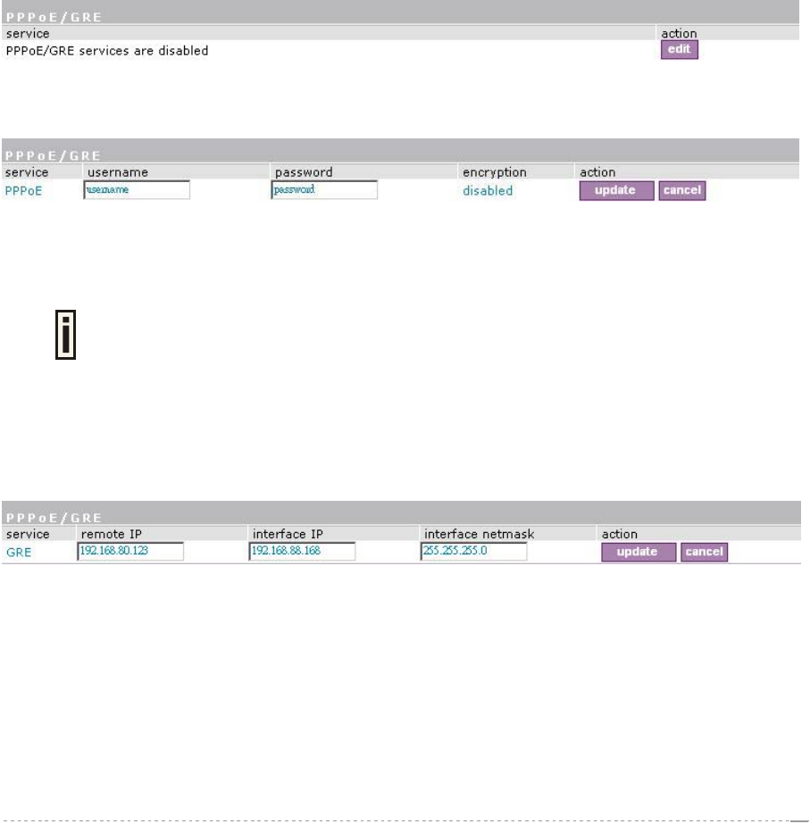
By default no services are available on the controller:
Figure 120 – PPPoE /GRE for DSL
To specify PPPoE tunnel for your controller click the edit button and enter the following:
Figure 121 – Specify PPPoE Tunnel
Service – select service PPPoE.
Username – enter username to connect to the server [text string, can not be empty].
The same username should be configured on the PPPoE server.
Password – enter password by which user should be authenticated [text string, can not be empty].
Encryption – enables use of MPPE encryption.
When PPPoE tunnel is used, then no server IP is required - broadcast address will be used.
To specify GRE tunnel for your controller click the edit button and enter the following:
Figure 122 – Specify GRE Tunnel
Service – select service GRE.
Remote IP – IP address of GRE tunnel endpoint [IP address].
Interface IP – enter the IP address of GRE interface [IP address].
Interface Netmask – enter the netmask of GRE interface [netmask].
BROWAN Page
77
User’s Guide Version 1.0
Network Interface | Tunnels | GRE Client for VPN
GRE (Generic Routing Encapsulation) tunnel is one of the solutions for tunneling private network over
the TCP/IP connection (e.g. PPTP, L2TP, PPPoE). GRE tunnel does not use encryption. It only
encapsulates data and sends it over the Internet. So the administrator should take care that no
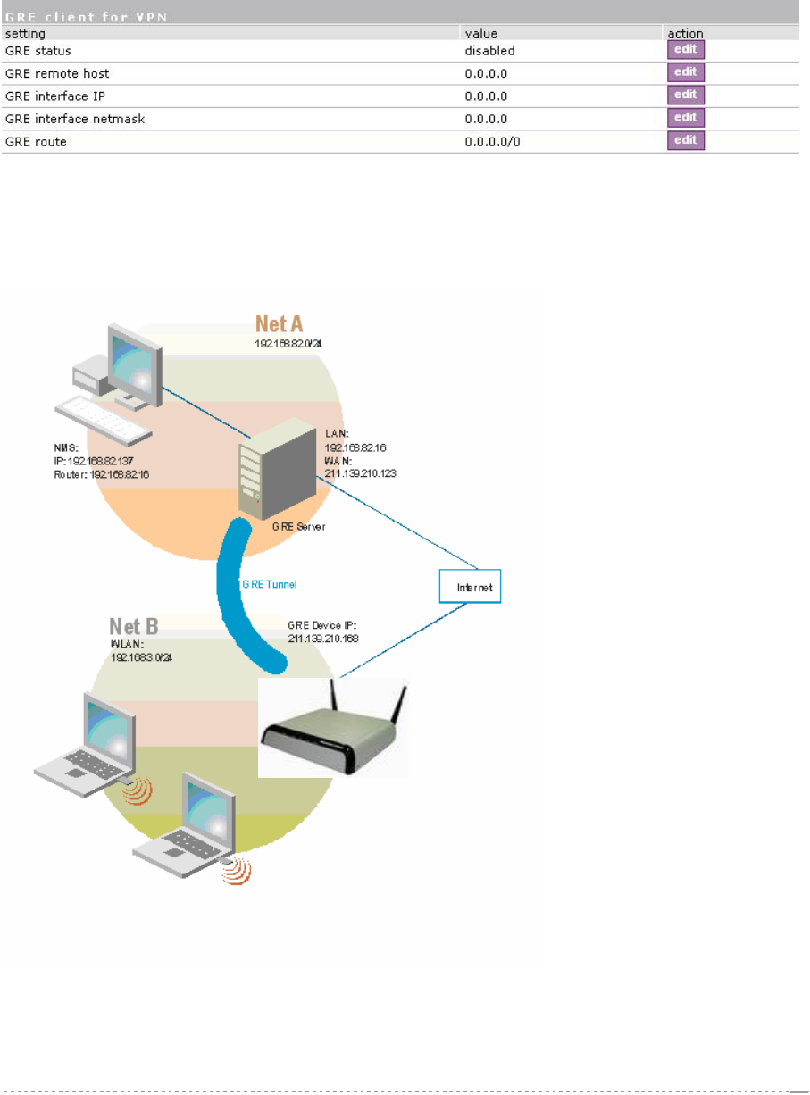
unencrypted private information is going through the GRE tunnel. By default there is no GRE tunnels
on the AC:
Figure 123 – GRE Tunnel
Click edit button to specify values
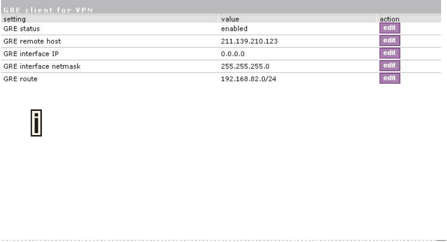
See the following example to understand GRE settings.
Example:
BW1330
Figure 124 – GRE Tunnel
BROWAN Page
78
User’s Guide Version 1.0
For example, there are 2 internal networks: network A and B, and intermediate network - Internet.
Network A (administrator's computer with Network Management System); we shall call this network
(192.168.82.0/24) “Net A”.
Network: 192.168.82.0
Netmask: 255.255.255.0
Router: 192.168.82.16
GRE server has two interfaces, LAN and WAN:
LAN IP: 192.168.82.16
WAN IP: 211.139.210.123
Network B has subscribers on LAN of BW1330 interface (ixp0) we shall call this network
(192.168.3.0/24) “Net B”:
Network: 192.168.3.0
Netmask: 255.255.255.0
Router: 192.168.3.1
Where GRE interface (WAN IP of AC) is 211.139.210.168.
GRE server
Remote Host IP: 211.139.210.168
Interface IP: 0.0.0.0
Interface netmask: 255.255.255.0
Route: 192.168.3.0/24
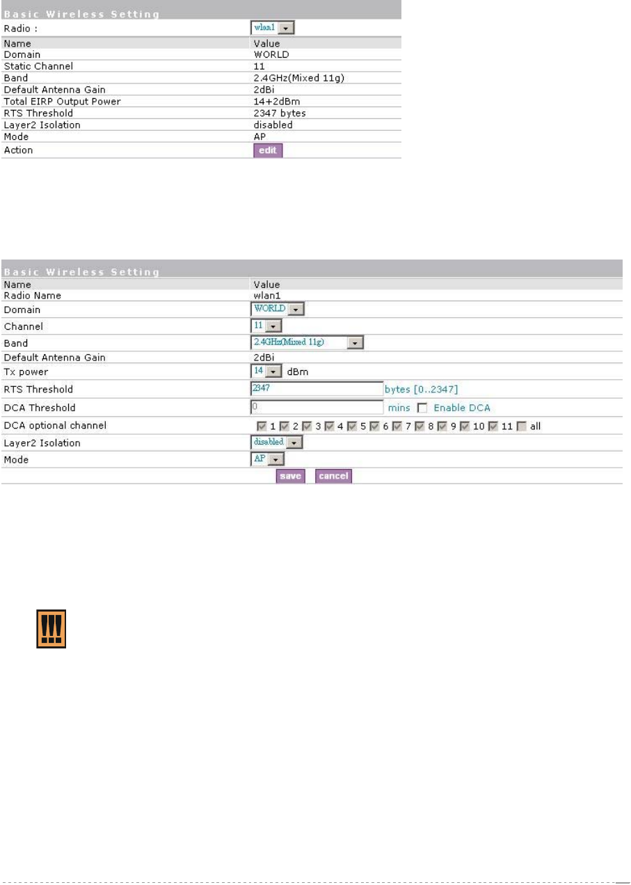
Refer to figure 125 the setting as below:
The setting of BW1330
GRE Remote Host IP: 211.139.210.123
GRE Interface IP: 0.0.0.0
GRE Interface netmask: 255.255.255.0
GRE Route: 192.168.82.0/24
Figure 125 – GRE client for VPN setting
The remote host IP address of “GRE client for VPN” is different with remote IP of
GRE service under Network Interface | Tunnels | PPPoE/GRE menu. You must
assign different IP address for the both GRE service enabled simultaneously.
As far as the Internet is concerned, we assume that it will pass any packet sent from Net A to Net B or
Net B to Net A. The administrator from Net A will be able to access clients on Net B through the GRE
tunnel between the GRE server and the GRE interface of AC.
BROWAN Page
79
User’s Guide Version 1.0
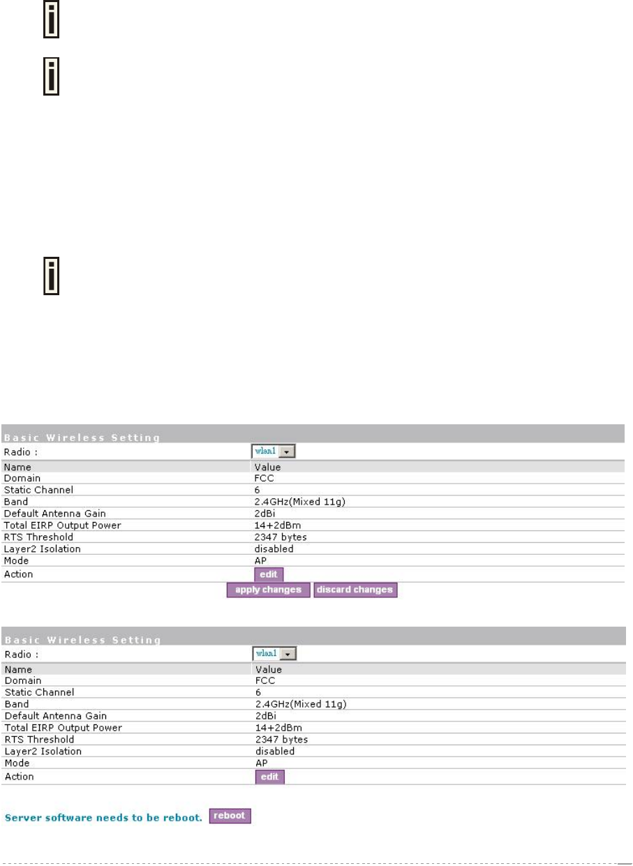
Network interface| wireless | Basic
Use the Network interface | wireless | Basic menu to configure such wireless settings as regulatory
domain, channel, band, and power, layer2isolation. Click the edit button on the setting to change the
basic configuration of wireless module.
Figure 126 – Basic Wireless Settings
Edit – edit the wireless basic settings
To change basic wireless setting properties click the Edit button in the Action column. The status
can be changed now:
Figure 127 – Edit Basic Wireless Settings
Radio Name– specify which wireless interface of BW1330, which is fixed: wlan1;
Domain – select the regulatory domain according to your country
The full frequency range of the 2.4 GHz is not permitted for use in all countries. Depending on your
selection of regulatory domains, the available frequency channels will vary.
Before changing radio settings manually verify that your settings comply with
government regulations. At all times, it will be the responsibility of the end-user to
ensure that the installation complies with local radio regulations. Refer to the
Appendix: B) Regulatory Domain/Channels.
Channels – select the channel that the access point will use to transmit and receive information. If
one channel is defined, it acts as default channel. Channels list will vary depending on selected
regulatory domain and selected band. Multiple frequency channels are used to avoid interference
between two radios of this AP, and between nearby access points. If you wish to operate more than
one access point in overlapping coverage areas, we recommend a distance of at least four channels
between the chosen channels. For example, for three Access Points in close proximity choose
channels 1, 6 and 11 for 11b/g.
Band – working bands on which your radios are working.
4 bands are supplied: 2.4GHz(Mixed 11g), 2.4GHz(11g only), 2.4GHz(Mixed 11g WiFi) and 2.4GHz
(11g only WiFi).If 2.4GHz(Mixed 11g) or 2.4GHz(11g only) is selected, the radio will work on 2.4GHz
BROWAN Page
80
2.33 dBi
20
18
2.33 dBi
User’s Guide Version 1.0
for a better performance. 2.4GHz (11g only) mode only allows 11g client access. 2.4GHz(Mixed 11g)
mode allows 11b/11g client access.2.4GHz(Mixed 11g WiFi) or 2.4GHz(11g only WiFi) can make sure
to compatible with Wi-Fi.
Tx Power – the BW1330 transmission output power in dBm. Different power level is based on domain
setting. Default is 18dBm&WORLD.
Total Output Power (EIRP) = Antenna Gain + RF card output power
The range of the EIRP varies with channel and regulatory domain.
RTS Threshold – when set, this settings specifies the maximum packet size beyond which RTS/CTS
mechanism is be invokes. The value range of this is [0 …2347]. Default is 2347 which means that
RTS is disabled.
DCA threshold – show the value (in minutes) of DCA threshold. This threshold is been used to judge
if there is no wireless users connected during this time. And if yes, BW1330 will monitor the
environment and adjust channel for the best operational one.
DCA optional channel – show the channels only in which auto channel selection (DCA) will be
processed to reduce interference.
Only when DCA is enabled, DCA threshold and DCA optional channel will be
shown.
Layer 2 Isolation – Layer2 wireless client separation. Connected clients with user isolation function
enabled cannot access each other directly. The clients are isolated from each other using their MAC
addresses [enabled/disabled].
Mode – the operating of Access Point[AP].
For such each change of settings, the BW1330 needs to be reboot to apply all settings changes when
clicking Apply Changes. Request for reboot server appears:
Figure 128 – Configuration changed
Figure 129 – Click apply changes button and reboot device
BROWAN Page
81
2.33 dBi
20 dBm
2.33 dBi
20
User’s Guide Version 1.0
Reboot – Click the button to restart the server and apply the changes.
And if there are still other setting modifications needed, go ahead to finish all
changes and then click Reboot button to restart and apply all settings.
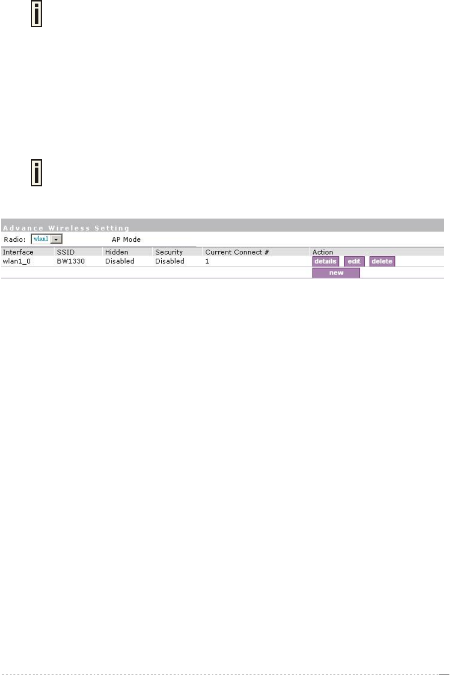
Network interface | wireless | Advance
BW1330 supports Multiple BSSID (MBSSID) function. You can configure up to 16 BSSIDs per radio
on BW1330 and assign different configuration settings to each BSSID. For wireless users, they can
think BW1330 as single AP with multi service supporting, including different security policy, different
subnet, different authentication etc. All the BSSIDs are active at the same time that means client
devices can associate to the access point for specific service. Use the Wireless | Advance menu to
configure properties related to Multiple BSSID, including configure SSID, Hidden SSID, and Security
for each SSID.
Each BSSID can have its own SSID. In this case, Multiple BSSID is the same with
Multiple ESSID. Wireless users can think BW1330 as multiple virtual APs, each
supporting different service, and connects one SSID for the special services.
Click edit or new button to modify or create virtual APs.
Figure 130 – Detail for MBSSID entry
Detail – Show the wireless settings of BW1330.
Edit – modify current virtual AP settings of SSID/Security etc.
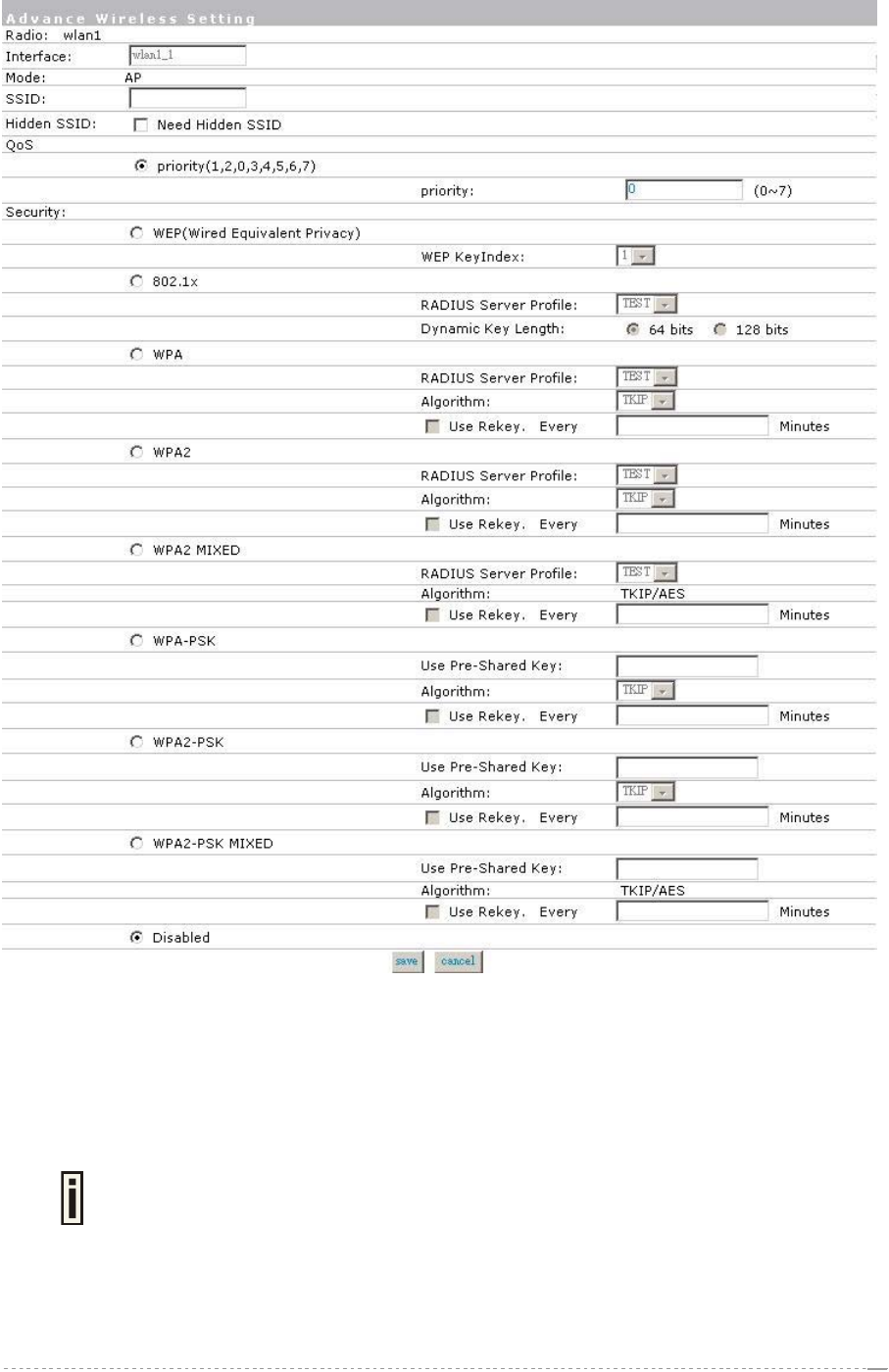
Clicking New or Edit on AP mode, the settings of MBSSID entry appears:
BROWAN Page
82
User’s Guide Version 1.0
Figure 131 – Multiple BSSID Setting
Radio – showing which RF card, for BW1330 it is fixed: wlan1;
Mode – showing the current operation mode, for BW1330 it is fixed: AP mode;
SSID – a unique ID for your wireless network. It is case sensitive and must not exceed 32 characters.
The SSID is important for clients when connecting to the access point. All client stations must have
their client SSID settings configured and must use the same SSID.
Each MBSSID entry (BSSID) can has its own SSID. And SSID can be same for
different BSSID
Hidden SSID – When enabled, the SSID of this Interface is invisible in the networks list while
scanning the available networks for wireless client (SSID is not broadcasted with its Beacons). When
disabled, the AP’s SSID is visible in the available network list [enabled/disabled]. By default the
Hidden SSID is disabled.
BROWAN Page
83

User’s Guide Version 1.0
QoS – Quality of Service, stand for the priority of this SSID, the value of QoS is from 0 to 7, with the
order: (1, 2, 0, 3, 4, 5, 6, 7), which 1 stand for the lowest priority which 7 stand for the highest priority.
Security – Specify the security policy.
WEP – When selected, the privacy of MSSID entry will be set to WEP (Wired Equivalent Privacy).
WEP Key Index – Select the default key Index to make it the Default key and encrypt the data before
being transmitted. All stations, including this MSSID Entry, always transmit data encrypted using this
Default Key. The key number (1, 2, 3, 4) is also transmitted. The receiving station will use the key
number to determine which key to use for decryption. If the key value does not match with the
transmitting station, the decryption will fail. The key value is set in Network interface | wireless | Sec
WEP page.
802.1x – When selected, the MSSID entry will be configured as an 802.1x authenticator. It supports
multiple authentication types based on EAP (Extensible Authentication Protocol) like EAP-TLS, EAP-
TTLS, EAP-PEAP, EAP-SIM. The privacy will be configured as dynamic WEP.
You must enable RADIUS Proxy in order for wireless 802.1x authentication to work
with BW1330. To enable RADIUS Proxy, please refer to Network Interface |
RADIUS | Proxy, the RADIUS Proxy default is disabled.
RADIUS Server Profile – Select the default radius server name. If not, please configure Network |
RADIUS Servers Web page first.
Dynamic Key Length – Select the dynamic 64-bits / 128-bits encryption.
WPA – Wi-Fi Protected Access, When selected, the encrypt method will be WPA with RADIUS Sever.
RADIUS Server Profile – The same as 802.1x.
Algorithm – Choose WPA algorithm (TKIP, AES).
Use ReKey – If not selected, indicates that Group Key will not be rekeyed. If selected, must
specify the time in minutes, after which the group key will be updated.
Every … minutes – Specify amount of minutes and WPA automatically will generate a new
Group Key.
WPA-PSK – When selected, the encrypt method will be WPA without RADIUS Server.
Use Pre-Shared Key – Specify more than 8 characters and less than 64 characters for WPA with
pre-shared key encryption.
Algorithm – The same as WPA.
Use Rekey – The same as WPA.
Every … minutes – The same as WPA.
MAC Auth – MAC authentication. When selected, the MAC address of username and password
will be passed to RADIUS server for PAP authentication when wireless client connects with BW1330.
RADIUS Server Profile – The same as 802.1x.
Disabled – When selected, no security policy will be applied.
Each time create a new MSSID or WDS, administrator need configure the relative
network configuration in menu Network interface | configuration | interface
configuration such as interface IP, netmask and also the DHCP configuration.
BROWAN Page
84
User’s Guide Version 1.0
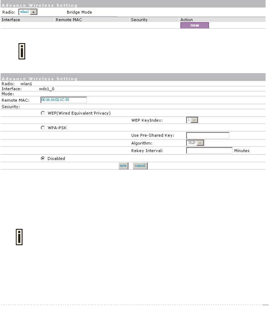
Network Interface | Wireless | WDS
A WDS (Wireless Distribution System) allows you to create a wireless network infrastructure.
Normally the access points must be connected with a wired network (LAN), which is generally an
Ethernet connection. Once connected, these access points create wireless cells allowing wireless
connection to the wired network. The WDS feature allows the access points to be wirelessly
connected to another access point, eliminating the need for a wired connection between them:
Data from a wireless client attached to an AP configured for WDS will be repeated on the wireless
interface to the peer AP where it will be delivered to it’s destination. Consequently , the overall
throughput of the wireless system is reduced by half for each relay link added.
WDS mode is configured by entering the WDS link peer AP’s MAC address in each other’s AP
configurations.
To configure the WDS links use the network interface | wireless | WDS menu, click the new button
and enter the MAC addresses of the peer APs:
figure 132 – WDS setting
The radio channel in all WDS link peer APs must be the same, although their
SSIDs may be different.
Configure WDS settings.Click the “new” button.
figure 133 – add WDS
Remote MAC- enter WAN MAC address of the peer AP for the WDS link [6-HEX pairs separated by
colon [1-9] [A-F] [a-f]].
Security- set WEP/WPA-PSK encryption or disable of WDS link.
Specify the WEP Key Index and use network interface | wireless | SecWep to set the WEP Key if
you choose the WEP encryption of WDS link.
You can discover the WAN (ixp1) MAC address of your BW1330 in the system |
status page.
BROWAN Page
85
User’s Guide Version 1.0
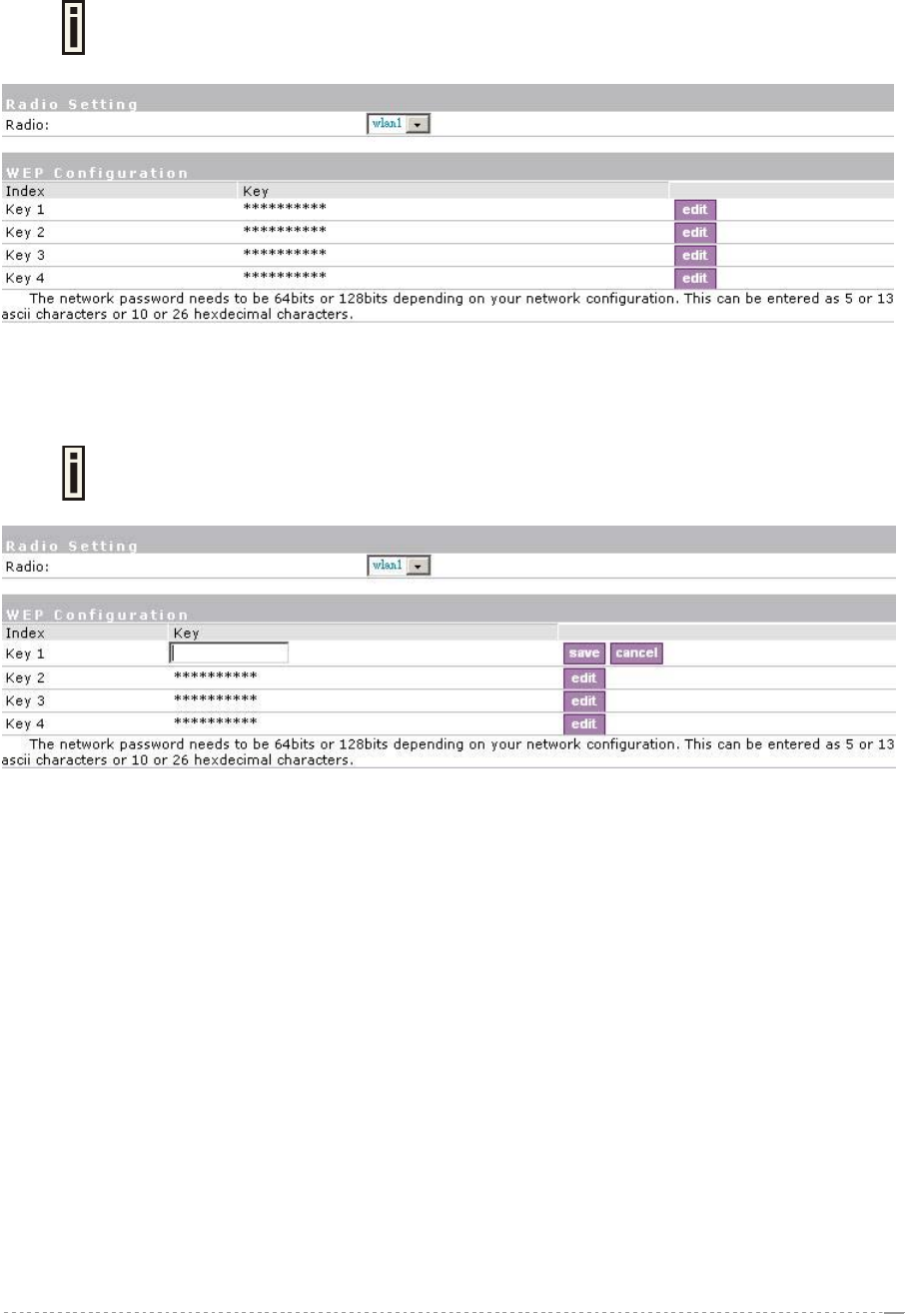
Network interface | wireless | Sec WEP
Use this menu to configure static WEP settings.
This menu only set static WEP key value related with 4 key indexes for wireless
module. Enable or Disable static WEP is in the Network interface | Wireless |
Advance menu.
Figure 134 – WEP Settings
Radio – specify which interface is needed to be set.
Click Edit to edit the existing WEP key1 to key4.
By default, four WEP keys are all set to “aaaaa”. They can be modified according to
real need.
Figure 135 – Edit WEP Key
BROWAN Page
86
User’s Guide Version 1.0
User Interface
Use the user interface menu to configure device settings affecting the user interface. If you need to
configure the: welcome/login/logout/help/unauthorized pages, administrator settings, start page or
free sites, use the user interface menu.
Figure 136 – User Interface Menu
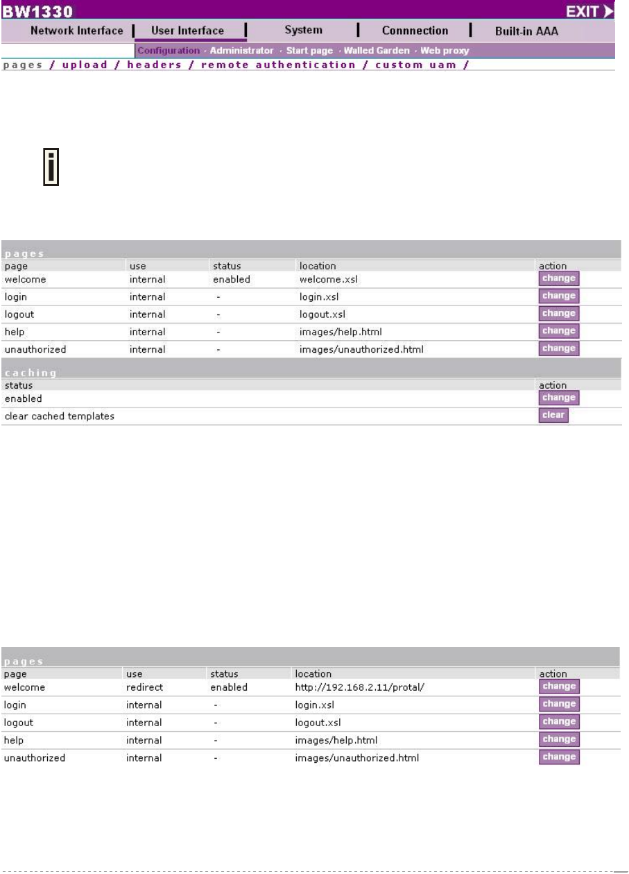
User Interface | Configuration | Pages
Detailed description about user page customization is given in the Chapter 4 –
User Pages.
The welcome/login/logout/help pages can be easily changed to user defined pages by choosing the
change button. The pages configuration menu is displayed by default:
Figure 137 – Available User Pages for Configuration
Welcome – first page the user gets when he/she opens its browser and enters the URL.
Internal – choose this option when using the internal user pages templates.
External – choose this option when uploading your own user pages templates.
Redirect – choose this option when using the Extended UAM login function (see Chapter 4,
section: Extended UAM).
Login/Logout/Help/Unauthorized – please refer to Chapter 4.
Status – choose enable/disable welcome page status. Note that redirect option with status ‘disabled’
would work.
Location – enter location for external templates or redirect (e.g. WAS IP address).
Figure 138 – Redirect User Pages
Welcome page with redirect option selected redirects the user authentication process to the
specified location. The user welcome/login/logout page can be implemented as simple HTML (not
required to use the .XSL or default user pages templates) in such case.
BROWAN Page
87
User’s Guide Version 1.0
The redirect location URL should be specified as Walled Garden URL, otherwise
the redirect would NOT WORK.
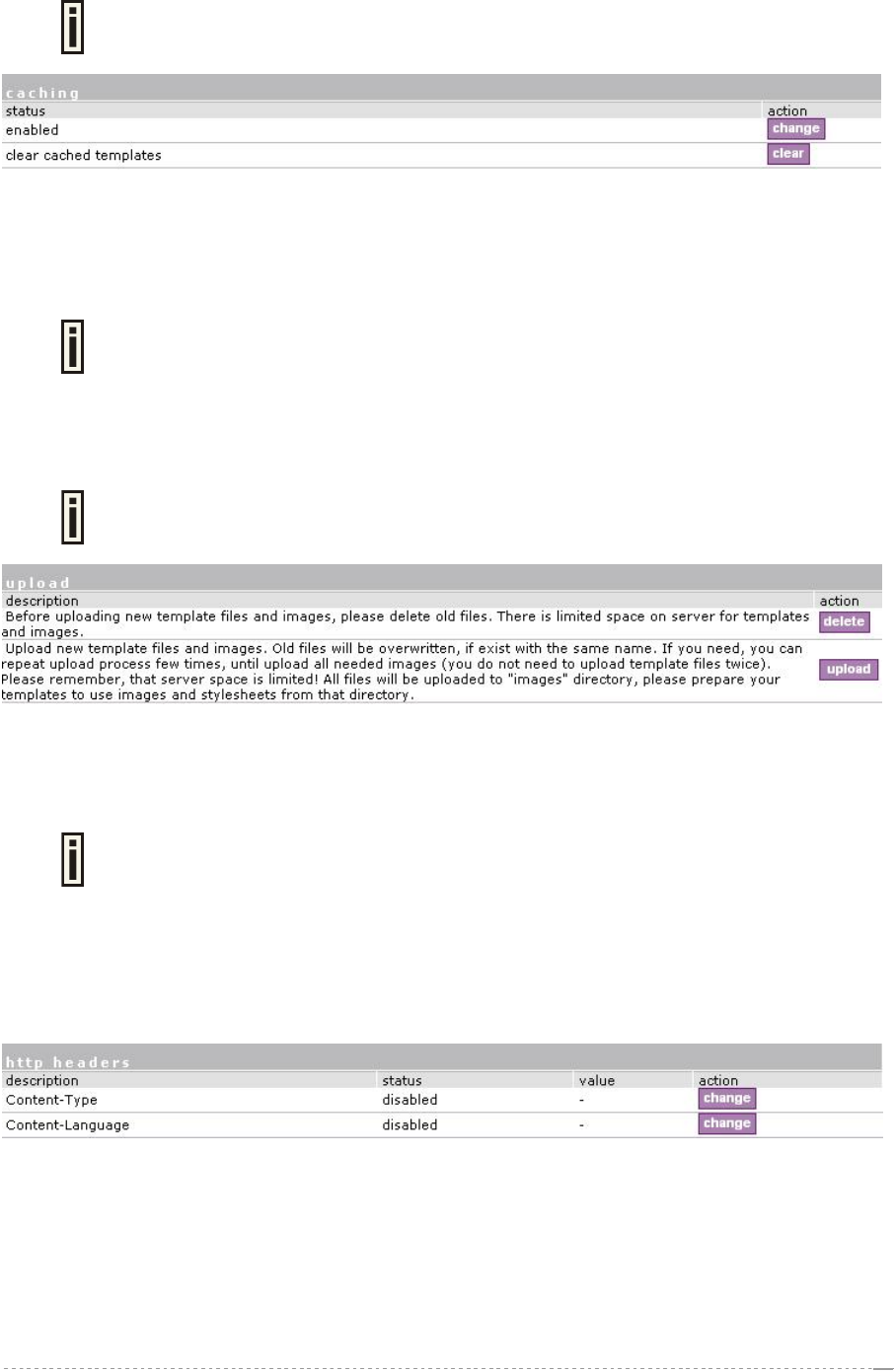
Figure 139 – Caching Option
Caching option can be used for caching the external uploaded user pages (available choice:
enabled/disabled)
Clear – click the button to clear cached user pages.
Controller cache is also cleared after device reboot/reset.
User Interface | Configuration | Upload
Look for the user pages template samples in the Installation CD delivered to you
with the product.
Figure 140 – Upload Page
Delete – click the button to delete earlier uploaded files from Access Controller memory.
Upload – click the button to select and upload new user pages.
How to upload user pages see in the Chapter 4 – User Pages.
User Interface | Configuration | Headers
System administrator can set HTML headers encoding and language settings for AC web
management interface and new uploaded user pages. Select user interface | configuration |
headers menu:
Figure 141 – HTTP Headers Settings
BW1330 device supports some http META tags. Syntax of such META tags:
<META HTTP-EQUIV="name" CONTENT="content">
Currently BW1330 supports Content-Type and Content-Language tags:
BROWAN Page
Content-Type is used to define document char set (used, when text has non-Latin letters, like
language letters).
Content-Language may be used to declare the natural language of the document.
88
User’s Guide Version 1.0
BW1330 automatically adds defined content-type and content-language to generated XML. Then user
pages (.XSL) templates will use these parameters to generate the output HTML.
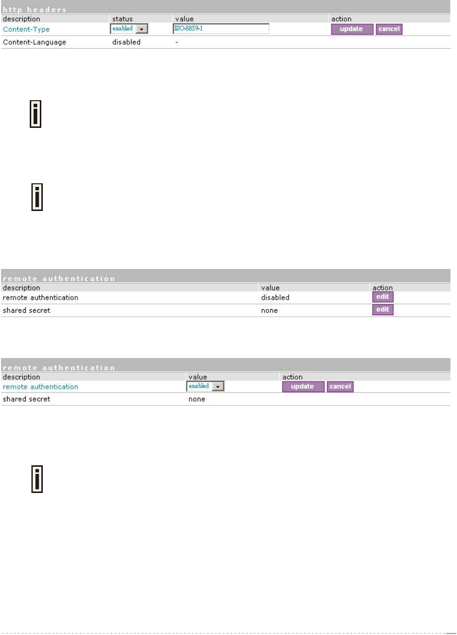
Click the change button to define new headers of the web management interface on user pages
templates. The default HTML encoding is ISO-8859-1, language = English. Enable the HTTP header
status and default values appear:
Figure 142 – Set HTTP Headers
The system administrator can set his own header encoding and language settings.
Use the HTML 4.01 specification to define the header encoding and language.
User Interface | Configuration | Remote Authentication
Read more about the extended UAM feature in Chapter 4, section: Extended
UAM.
The Remote Authentication feature under the user interface | configuration menu allows an
external Web Application Server (WAS) to intercept/take part in the user authentication process, and
to log on and log off users externally. It provides a means to query user session information as well.
By default such remote authentication is disabled:
figure 143 - Remote Authentication
Click the edit button next to appropriate settings to specify remote authentication parameters:
figure 144 – Enable Remote Authentication
Remote Authentication – select status: [enabled/disabled].
Shared Secret – enter password for WAS to communicate with AC [sting (4-32), no spaces allowed].
The shared secret must match that configured on the WAS. This shared secret
allows the WAS to initiate a secure (SSL) command session with the BW1330 to
pass login commands.
User Interface | Configuration | Custom Uam
Customized UAM let hotspot owner upload their own login and logout page to BW1330 to apply with
hotspot or enterprise style or do advertisements.
User customized page is based on HTML. User can use Microsoft FrontPage to edit their login and
logout page and upload their pages to BW1330.
BROWAN Page
89
User’s Guide Version 1.0
These features are aim to the facility of people who has no knowledge on XSL and replace the menu:
user interface| Configuration| {pages, upload}.
BW1330 support internal and external customized UAM. Internal means user can upload their html
login and logout page to BW1330. External means BW1330 will go to an external web server to fetch
login and logout page the local and push to web login client.
Customized UAM in default is disabled and user web login page will be the default page as chapter 4
descript. Enable the configuration if you want to use customized UAM function.
Click edit button to configure customize page.
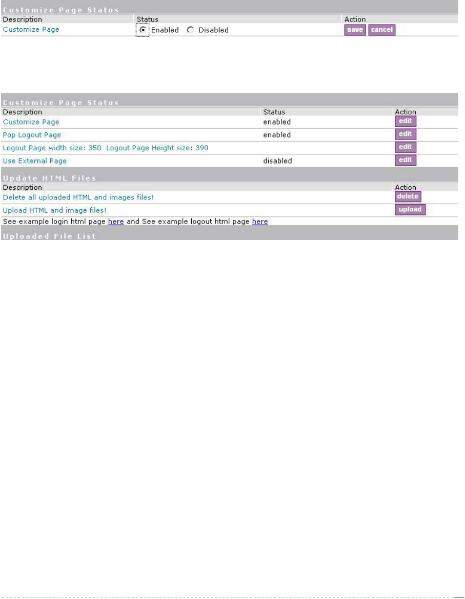
Figure 145 – Customized UAM Page enabled
After successfully enabled customized UAM configuration, this configuration page will be extended to
the follow page which includes three columns.
Figure 146 – Customize UAM enabled
First is Customized UAM status configuration:
Customized Page – Enable or disable customized UAM
Pop Logout Page – After user successful web login, if this item is enabled, AC will pop out a
logout page for user. In default this setting is enabled if customized page is enabled.
Logout page’s dimension – For the difference of logout page’s dimension which make by
customer, AC will use this data to pop out user’s customized logout page.
Use External Page – If this item is enabled, AC will fetch login and logout page from an external
web server.
Second is update html files, for user delete or upload login and logout pages. There also has two URL
point to example page in html format for login and logout page which user can reference to make their
own pages.
The third is uploaded file list, where user can find which files have been uploaded.
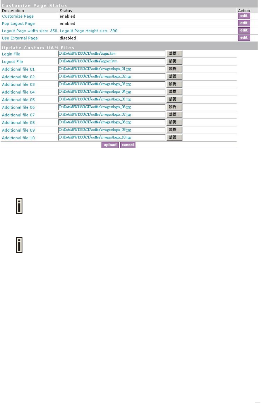
Press upload button on second column will coming into upload files pages:
BROWAN Page
90
User’s Guide Version 1.0
Figure 147 – Upload pages
Login File is for customized login page; Logout File is for customized logout page.
Additional file 01~10 is for uploading picture and CSS files. Current support picture file format is
JPG,GIF,PNG and CSS.
Picture and CSS files name need be consistent with your login or logout html
pages. The login and logout html file can be what ever you want.
Don’t forget fill out the Logout page’s dimension. User maybe can only see part
of your logout page without dimension specified.
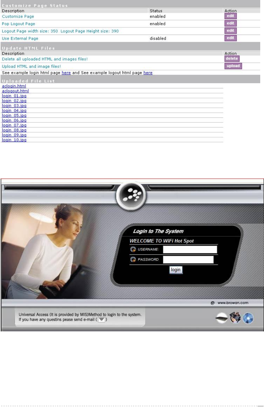
After select the file you want, press upload button and the files will upload to BW1330. After
successful upload files, you can see the page below:
BROWAN Page
91
User’s Guide Version 1.0
Figure 148 –Flash upload files OK
After successful flash the files, uploaded files will appear in uploaded file list.
Next is an example for customized login and logout page.
Figure 149 –Example login page
BROWAN Page
92
User’s Guide Version 1.0
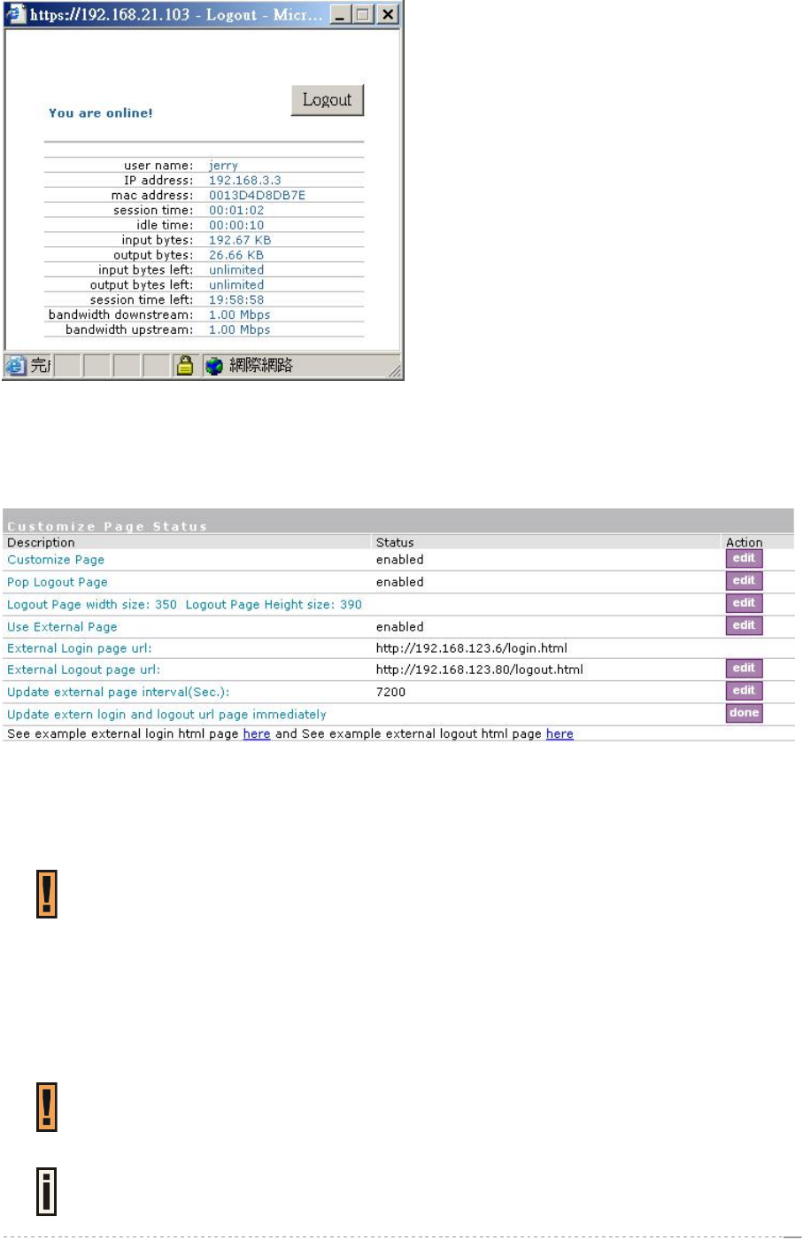
Figure 150 –Example logout page
For external pages, enabled the “use external page” in the first column of Customize Page Status:
Enable Use External Page option and click edit button for the URL specify and save it then click done
button to finish the setting.
Figure 151 –External page configuration
Fill out the external login page URL and external logout page URL. BW1330 would auto-update the
external page every 7200 seconds or you change the interval update time. External page example
will be found in the links under the last line.
In External page mode, BW1330 will only fetch the login and logout html page to local,
the picture or the CSS file which link on the customized login/logout page will not be
fetch. So the link to the picture and CSS file on user customized html file need to be an
absolute address which point to the external web server.
To issue of logout command, the logout html syntax will need to refer to BW1330
domain name. For instance, if BW1330 domain name is www.BW1330.com and the
logout html syntax would be:
<A href="http://www.BW1330.com/logout.user?cmd=logout" >.You can set BW1330
domain name in system| configuration| domain name
If use external page, the external web server address need to be added to the walled
garden which descript in User Interface | Walled Garden for login user free to access.
BW1330 would use the default login or logout page if user did not upload the
customized pages or BW1330 did not get the external page from the external
login/logout page URL.
BROWAN Page
93
User’s Guide Version 1.0
User Interface | Administrator
The administrator menu is for changing the administrator’s settings: user name, password and
session timeout:
There are two kinds of administrator for BW1330: one is the super administrator and the other is the
normal administrator or named ebilling administrator.
Super administrator has the full power to manage BW1330; While the normal administrator with
limitation authority to access some menus list as below:
User interface | start page
User interface | walled garden(URLs column)
system | configuration | clock
system | access | web auth
system | access | status
Connection | Users
All menus under Built-in AAA | E-Billing
All menus under Built-in AAA | Pre-paid except “receipts” and “manage net print” menus.
All menus under Built-in AAA | Configuration except “backup and restore” menu.
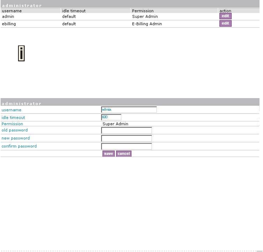
The administrator menu is for changing the super administrator and normal administrator (ebilling
administrator)’s settings: user name and password:
Figure 152 – Administrators Settings
Default super administrator logon settings is:
User Name: admin Password: admin01
Default normal administrator logon settings is:
User Name: ebilling Password: admin01
To edit or change the super and normal administrator settings click the edit button:
Figure 153 – Change Administrator Setting
Username – administrator username for access to Access Controller (e.g. web interface, CLI mode)
[1-32 symbols, spaces not allowed].
Idle Timeout – amount of administrator inactivity time, before automatically disconnecting
administrator from the web interface [300-3600 seconds]. The default idle time: 10minutes (600
seconds).
Permission – permission rights of this account, cannot be changed.
Old Password – old password value.
New Password –new password value used for user authentication in the system [4-32 symbols,
spaces not allowed].
BROWAN Page
94
User’s Guide Version 1.0
Confirm Password – re-enter the new password to verify its accuracy.
Save – click to save new administrator settings.
Only super administrator can change the settings of super administrator and normal
administrator.
User Interface | Start Page
The start page is the default web page where users will be redirected after log-on. This value will be
overwritten by the WISP RADIUS attribute no.4 "Redirection-URL" if provided in the authentication
response message. Use the user interface | start page menu to view or change the start page URL:
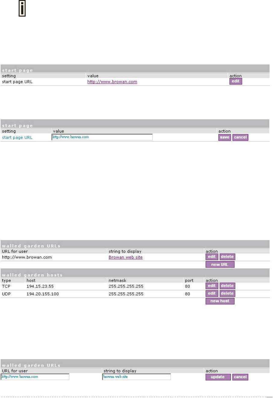
Figure 154 – Start Page
The administrator can change the start page by clicking the edit button. The value entry field will
change into an editable field:
Figure 155– Edit Start Page
Value – enter new redirection URL of start page in valid format [http://www.startpageurl.com].
Save – to save new settings.
Cancel – restores all previous values.
User Interface | Walled Garden
The walled garden is an environment that controls the user's access to Web content and services.
This feature gives the ability to define a free, restricted service set for a user not yet logged into the
system. Use the user interface | walled garden menu to view or change the free URLs or hosts.
Figure 156 – Walled Garden
Edit – edit the selected URL or host. All settings become available for editing.
Delete – delete the selected URL or host.
New URL – click the new URL button and enter the new URL and its description. Save entered
information by clicking the update button:
Figure 157 – Add New URL part 1
BROWAN Page
95
User’s Guide Version 1.0
URL for User – define full URL address [ex:www.browan.com].
String to Display – site description.
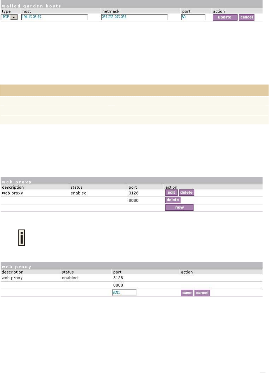
New Host – If you need to define hosts (web servers) for walled garden, specify hosts by clicking the
new host button and click the update button:
Figure 158 – Walled Garden Host
Type –select the data traffic protocol for host server [TCP/UDP].
Host – Web server address [IP address or host name].
Netmask – enter the network mask to specify the host servers network.
Port – network port, which is used to reach the host [1-65535]. For standard protocols use the default
ports:
Protocol Port
HTTP 80
HTTPS 443
FTP 21
User Interface | Web Proxy
The enabled web proxy allows any clients’ connections with configured proxy settings on their
browsers. The AC accepts any client proxy configurations and grants the access to the Internet. The
system administrator should list only ports the AC is listening on for proxy requests.
Figure 159 – Web Proxy
Web proxy is enabled by default and the port numbers are: 3128 and 8080.
To add more port number for web proxy, click the new button:
Figure 160 – Add Web Proxy Port
Port – add port number for web proxy to listen to [1-65535].
Save – click the button to save new port.
BROWAN Page
96
User’s Guide Version 1.0
System
Use the system menu to configure such system utilities:
Syslog – for sending system and debug messages via the syslog protocol.
Clock – manual setting of internal device clock.
NTP – set the Network Time Protocol service on the AC.
Certificates – upload your own SSL certificate and private key files for server.
Save and Restore – save current AC configuration and restore.
Use the system menu to define default access/visitor access to the device via or using:
Telnet – enable telnet connections to AC.
AAA – enable different AAA methods.
UAT – enable the service.
SNMP – enable/configure SNMP management.
Use the system menu to check the system status, reset the device, or update with new firmware.
Figure 161 – System Menu
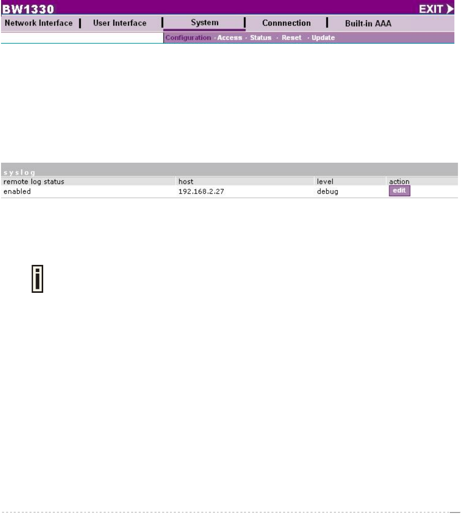
System | Configuration | Syslog
You can trace your AC system processes and get the system log messages remotely using the
system | configuration | syslog menu (by default the syslog utility is disabled):
To enable the syslog remote sending function, click the edit button and choose the enabled option:
Figure 162 – Syslog Settings
Remote Log Status – choose disable/enable remote log [enabled/disabled].
Host – specify the host IP address where to send the syslog messages [host IP address].
Be sure the remote host is configured properly to receive the syslog protocol
messages.
Level – select the messages level you need to trace. The level determines the importance of the
message. The levels are, in order of increasing importance:
Debug – debug messages including more important level messages: [info/warning/error/fatal].
Informational – informational messages including [warning/error/fatal]
Warning – warning condition messages including [error/fatal]
Error – error and critical condition messages including [fatal]
Fatal – critical and fatal condition for device messages. Actions should be taken immediately.
Save – save changes. The syslog messages will be started to send to the specified host.
Cancel – restore the previous values.
BROWAN Page
97
User’s Guide Version 1.0
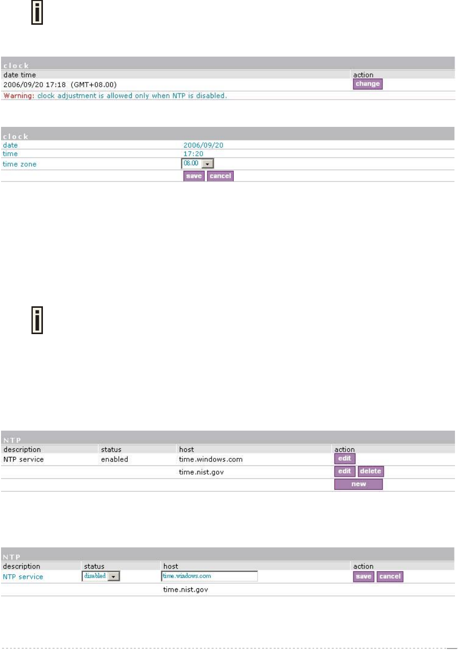
System | Configuration | Clock
To set the Wireless PAC internal clock, use the clock utility, accessed by selecting the system |
configuration | clock menu link:
clock adjustment is allowed only when NTP is disabled.
To adjust the clock settings, click the change button:
Figure 163 – Clock Utility
Figure 164 – Set Clock Settings
Date – specify new date value [year/month/day].
Time – specify time [hours: minutes].
Time Zone – select the time zone [-12.00 – 14.00]. If the NTP service is enabled the selected time
zone will be applied to the clock settings also.
If the NTP server (see the next section for reference) is enabled on the system, no manual clock
setting is available except time zone.
Only time zone change is available when NTP server is used.
System | Configuration | NTP
The NTP (Network Time Protocol) is used to synchronize the clock of the AC to a selected time
reference. You can synchronize the system clock settings using the system | configuration | NTP
menu:
Figure 165 – NTP Service
By default NTP service is enabled with two server: time.windows.com and time.nist.gov. To disable
the service, click the first edit button:
Figure 166 – Disable NTP
Status – select appropriate status for NTP service [enabled/disabled].
BROWAN Page
98
User’s Guide Version 1.0
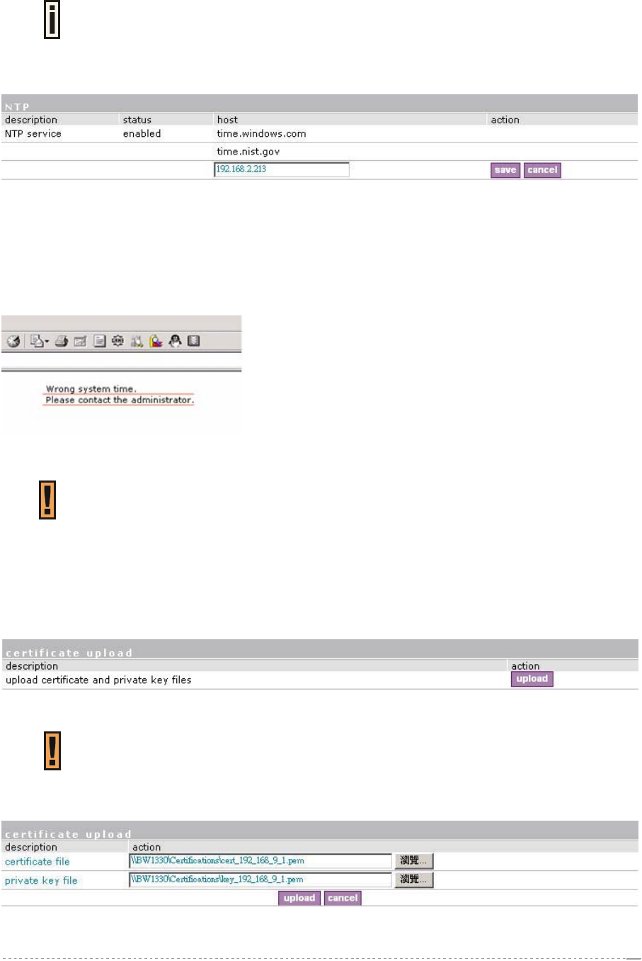
Host – specify the trusted NTP server IP on the field. It works only with enabled NTP function.
The NTP synchronize the device clock with GMT + 0 time. If you need to set the
time zone, use the system | configuration | clock menu.
You may want to add more than one NTP host, for example, in the case where the first host fails to
connect. Click the new button to add additional host settings:
Figure 167 – Add New NTP Host
Host – add additional NTP service hosts [1-128]. This NTP server will be used, if connection to the
first defined NTP server is lost.
If the system not right when BW1330 start up, the Pre-paid account and E-Billing account can not be
created, and UAM login page would not be popped out but replace with below figure. At this case
administrator need check if NTP works or adjust the clock manually.
Figure 168 – Wrong system time when user login
For BW1330 has no RTC, the default setting of NTP is enabled and the default
server is time.windows.com. NTP enabled is necessary for E-Billing account
and pre-paid account.
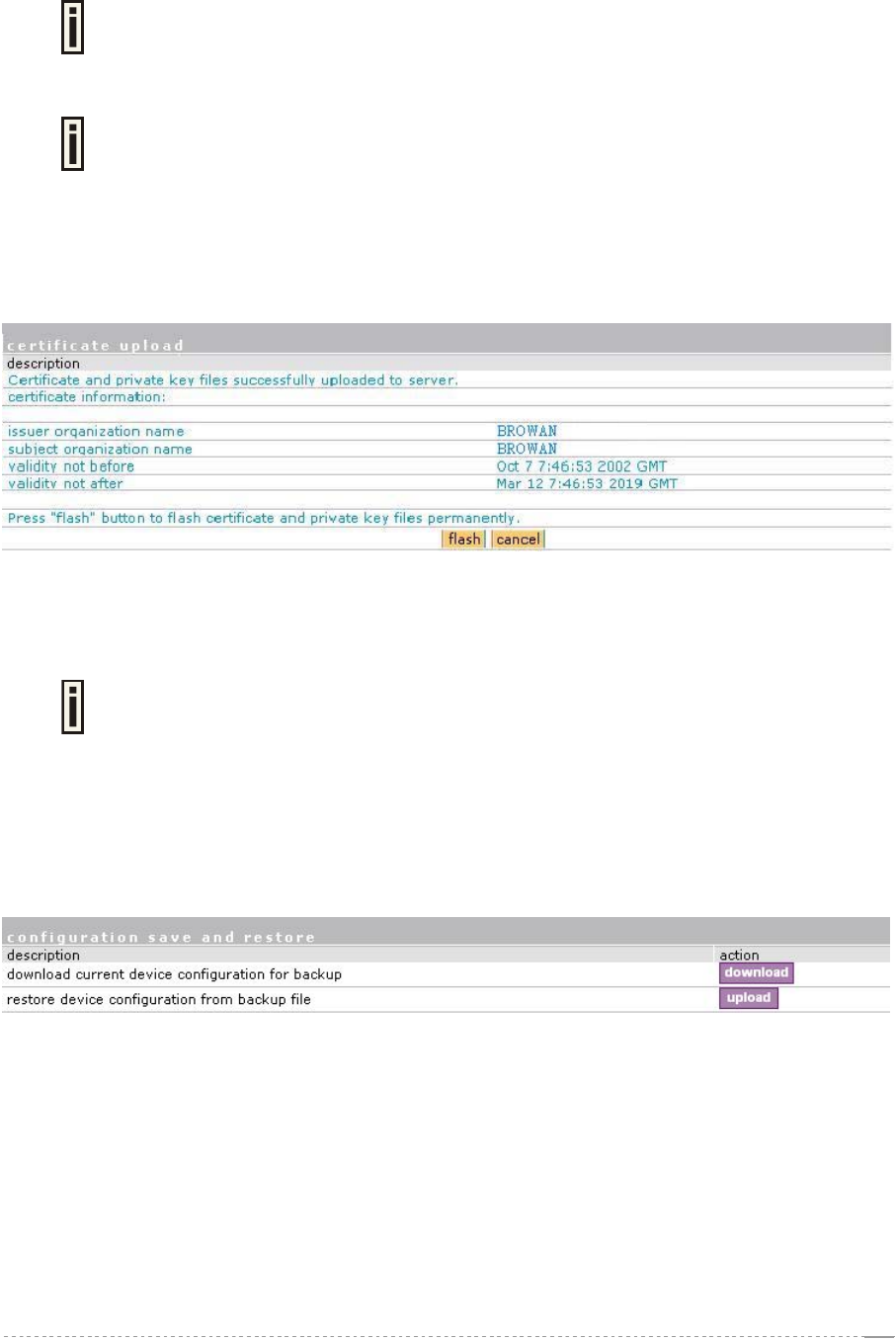
System | Configuration | Certificate
You can upload your own SSL certificates files for HTTP connection using the certificate menu under
the system | configuration menu:
Figure 169 – Certificate Upload
Only these certificate files are accepted:
Server PEM-encoded X.509 certificate file
Server PEM-encoded private key file
Click the upload to upload your own SSL certificates and private key files:
Figure 170 – Upload New Certificate
BROWAN Page
99
User’s Guide Version 1.0
Certificate File – the PEM-encoded certificate file for the server.
Corresponding RSA or DSA private keys SHOULD NOT be included.
Private Key File – the PEM-encoded private key file for the server.
Private key SHOULD NOT be encrypted with a password. This private key should
correspond to the certificate above.
Upload – upload new certificates.
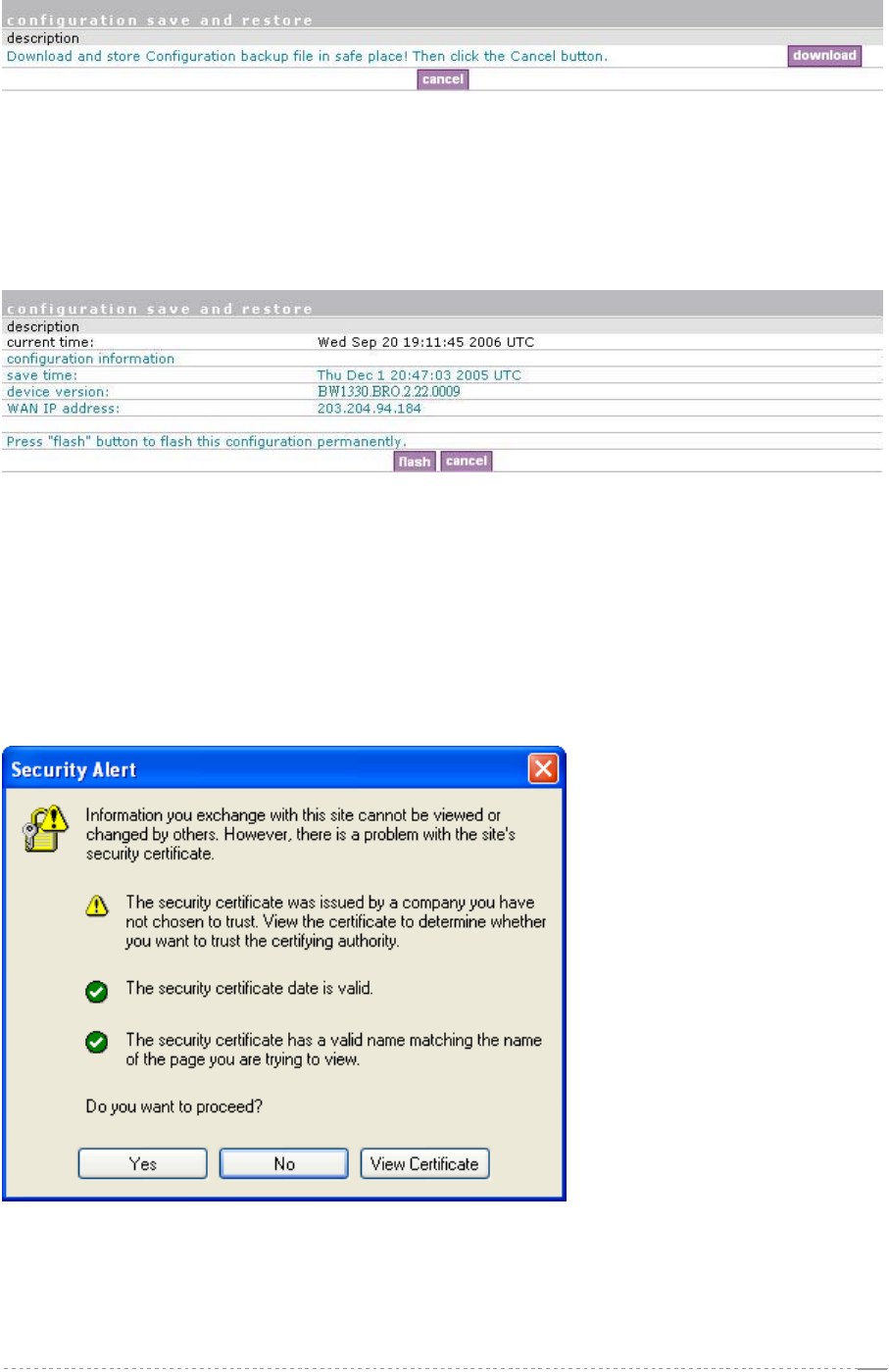
Depending on the public key infrastructure implementation, the certificate includes the owner's public
key, the expiration date of the certificate, the owner's name, and other information about the public
key owner. The default certificate implemented in the AC includes the following:
Figure 171 – Default Certificate Properties
Flash – upload new certificates into the controller.
Cancel – cancel new certificate upload.
Uploaded certificate and key file can not be removed, should over write by new
uploaded files.
System | Configuration | Save and Restore
You can save your current device configuration file locally using the save and restore menu under
the system | configuration menu:
Figure 172 – Save and Restore
Such device configuration is saved in the specific format file (.cfg):
Network configuration settings (including network interface, VLAN, port forwarding, route,
management subnet, DHCP, DNS, RADIUS, tunnels)
User interfaces configuration settings (including user pages templates)
System configuration settings (including syslog, NTP configuration, access settings)
Connection settings (including e-mail redirection and station supervision)
Click the download button to start saving the configuration file. You can change or leave the default
configuration file description:
BROWAN Page
100
User’s Guide Version 1.0
Figure 173 – Edit Configuration File Description
Download – click the download once again to save the configuration file under the selected path in
your computer. Now the last saved configuration is successfully stored in your local computer.
Cancel – click the cancel button to back to main configuration page.
You can use this file any time you want to restore this configuration to the device by using the upload
button. Select the configuration file and upload it on the device:
Figure 174 – Upload Configuration File
Flash – click the button to apply configuration setting to the device.
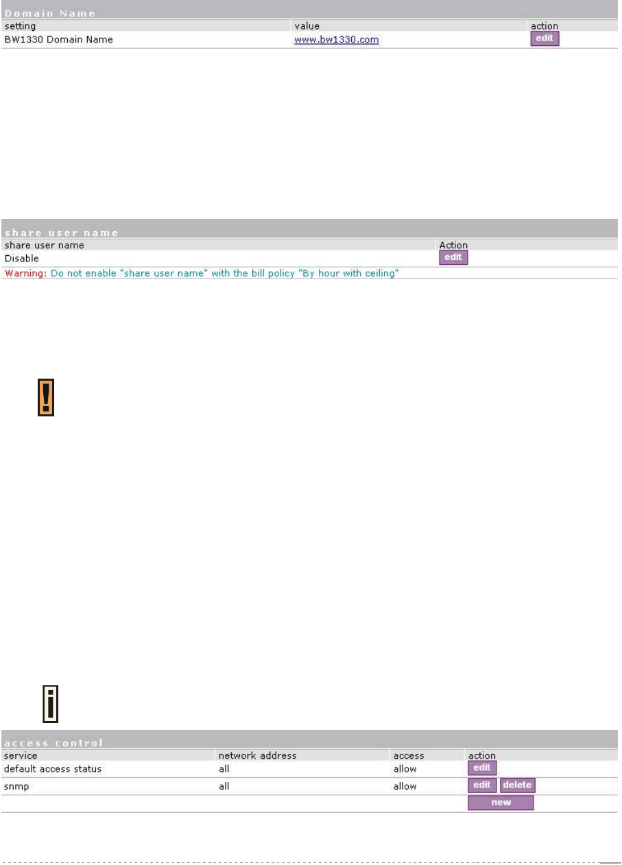
System | Configuration | Domain Name
Domain Name configuration is aimed to let many BW1330 use one uniform digital certificate. When
client use https connect with BW1330 for security, it needs a digital certificate which installed on
BW1330 to setup HTTPS connections. For the digital certificate, if one of the below conditions can not
meet, a warning window will pop out on client’s browser.
Figure 175 –Warning Window for digital certificate
1) Certificate is not issued by a trusted site;
2) Certificate is not expired;
3) Host name match with what is on Certificate.
BROWAN Page
101
User’s Guide Version 1.0
Condition 1 and 2 can be met if operator applies a right certificate. We use Domain configuration on
BW1330 to meet the condition 3.
Please fill-out the domain name use the format such as a URL, for example: www.bw1330.com,
which will be the same with the “host name” on the digital certificate. Create a new certificate with
hostname = www.bw1330.com and then install on BW1330.
Figure 176 –Domain Name configuration
And after that, the third item which “the security certificate has a valid name matching the name of
page you are trying to view” will be OK.
System | Configuration | Share Username
Use the Share Username menu to control the status (disabled/enabled) of if one user account can be
shared with more than one client.
Figure 177 – Share user name
if the share user name setting is “disable”, it means that one user account only can be used by one
client simultaneously; In another hand, if the setting is “enable”, it means multi-clients can share one
user account simultaneously.
“Share User” enable is using is the scenario that venue owner allow two or three
client use only one account simultaneously. The default setting is disabled.
System | Access | Access Control
Use the access control menu to control management access to your AC and to specific services.
Access control to your device includes access to these services:
Telnet
SSH
SNMP
The administrator can control access to the controller via telnet, SSH or SNMP for all users of for
individual users. This is done by creating an access control list in the AC and checking the incoming
user’s IP address.
Default access status is used to deny or allow all connections to the controller except those using
the SNMP service.
The SNMP service is used to provide access to your device from the KickStart
utility.
Figure 178 – Access Control
BROWAN Page
102
User’s Guide Version 1.0
Edit – click to edit the default access status [allow/deny].
New – click to create new access control rule for specific network to specific service(s) [all/
/ssh/telnet/snmp].
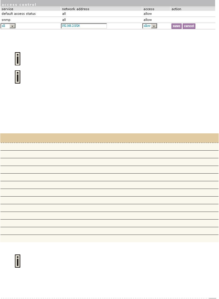
To configure the access control, click the edit button and specify the network address and select
services to allow/deny:
Figure 179 –Modify Access Control
Service – select services that access you need to control [all/ssh/telnet/snmp].
Telnet service must be separately enabled under system | access | telnet to
enable the telnet deamon on the controller.
BW1330 will first match the allow rules, then match the deny rules. In another
words, allow rules has the higher priority than the deny rules.
The default access rule has the lowest priority to other rules whenever its status is
allow or deny.
Network Address – specify the network or host address with netmask in bit format separated by a
forward slash.
The /N stands for the number of bits that are in the network address. There are 32 bits, so we have
32-N bits left that are part of the network. The first N bits of x.x.x.x correspond to x.0.0.0 when N=8,
our network address, and the netmask is 255.0.0.0 (when N=8).
bits netmask
/32 255.255.255.255
/31 255.255.255.252
/30 255.255.255.248
… …
/26 255.255.255.192
/25 255.255.255.128
/24 255.255.255.0
… …
/16 255.255.0.0
… …
/8 255.0.0.0
… …
/0 0.0.0.0
Access – select the access policy: [allow/deny].
Up to 255 different access control rules can be set.
BROWAN Page
103
User’s Guide Version 1.0
System | Access | Telnet
When the telnet function is switched on, telnet connection to the Wireless PAC is enabled and the
administrator can connect to the CLI interface via telnet.
Make sure that default access status to the administrator PC appears as ‘allow’
under the system | access | access control menu. Otherwise, you will not be able
to connect via telnet, even though the telnet function is enabled.
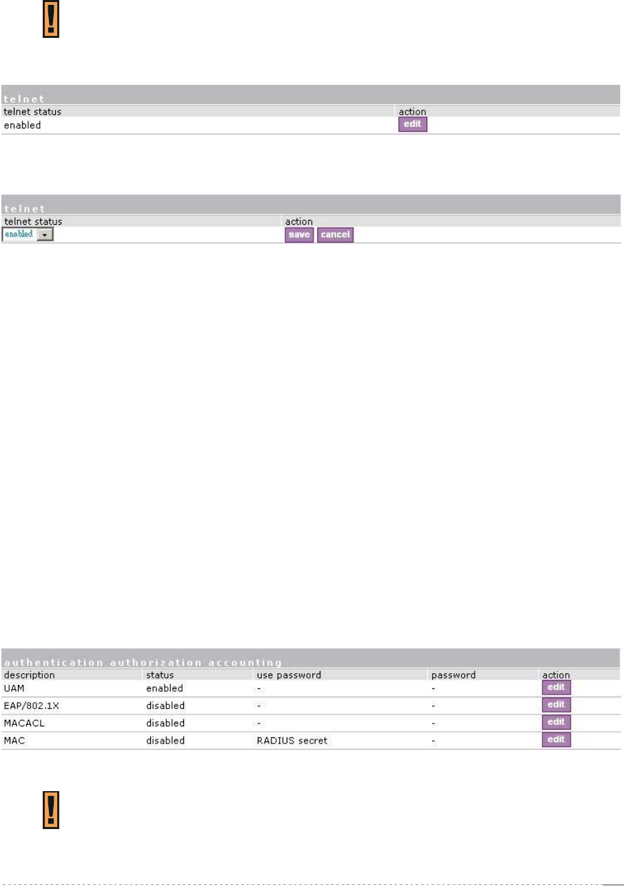
By default telnet is enabled:
Figure 180 – Default Telnet Status
To switch the telnet function on, click the edit button and change the status:
Figure 181 – Change Telnet Status
Enabled – connection via telnet to AC is enabled.
Disabled – connection via telnet to AC is disabled.
Save – click the button to save the configuration.
Cancel – restore the previous value.
System | Access | AAA
Such multimode Authentication, Authorization and Accounting (AAA) methods are supported on
the AC:
UAM – Universal Access Method (web-login) method
EAP/802.1x are:
EAPMD5 – 802.1x authenticator with MD-5 method
EAPSIM – 802.1x authenticator with SIM authentication method
EAPTLS – 802.1x authenticator with TLS authentication method
EAPTTLS – 802.1x authenticator with TTLS authentication method
MACACL– user is authenticated local database on BW1330 by its MAC address.
MAC – user is authenticated from RADIUS server by its MAC address.
Use the user interface | configuration | AAA menu to enable/disable appropriate authentication
method on your controller:
Figure 182 – AAA Settings
If UAM (web-login) method is disabled the subscriber will not be able to login
through the web interface.
BROWAN Page
104
User’s Guide Version 1.0
When enabled 802.1x authentication in this menu, it will only take effect for the
wired connection of the BVW1330. For wireless 802.1x authentication, please refer
in Network interface | wireless | Advance section to enable 802.1x for wireless.
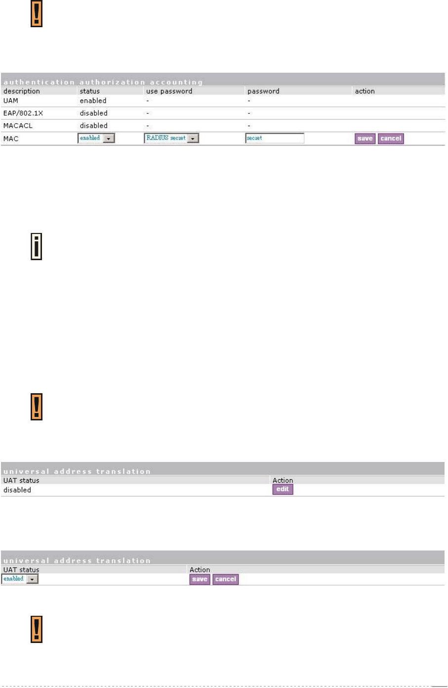
Status – change status of selected AAA method [enabled/disabled].
For MAC-RADIUS authentication the following settings are required:
Figure 183 – MAC-RADIUS Authentication
Use Password – select [RADIUS secret] or [User defined] password for user authenticating by its
MAC address.
Password – enter password with user-defined option selected. Password will be one for all users
authenticated by MAC address [string, 4-32 characters, no spaces allowed].
Current RADIUS secret value is only displayed and CANNOT be changed under
the AAA menu. To change the RADIUS secret value use the network interface |
RADIUS | servers menu.
For MAC-ACL authentication, BW1330 will use the local MAC address database, which can be
configured on system | Access | MAC List.
System | Access | UAT
With Universal Address Translation (UAT) enabled, the Wireless PAC will automatically and
transparently translate fixed IP settings (IP address, gateway, DNS, proxy server) on a user’s PC so
that he can connect to the broadband Internet service. There is no need for end-users to reset their
corporate IP or web settings. Also outgoing subscriber e-mails can be redirected to the operator's e-
mail server in order to facilitate e-mail forwarding for foreign subscribers.
Universal address translation works only on LAN and VLAN interfaces with
authentication setting enabled (see more about these settings in the
System | Access | NAV).
The Universal Address Translation (UAT) function can be enabled using the system | access |
UAT menu.
Figure 184 – Universal Address Translation Settings
To change UAT settings on interface click the edit button in the action column. The status can be
changed now:
Figure 185 – Change Universal Address Translation Status
BW1330 current support 50 UAT clients simultaneously.
BROWAN Page
105
User’s Guide Version 1.0
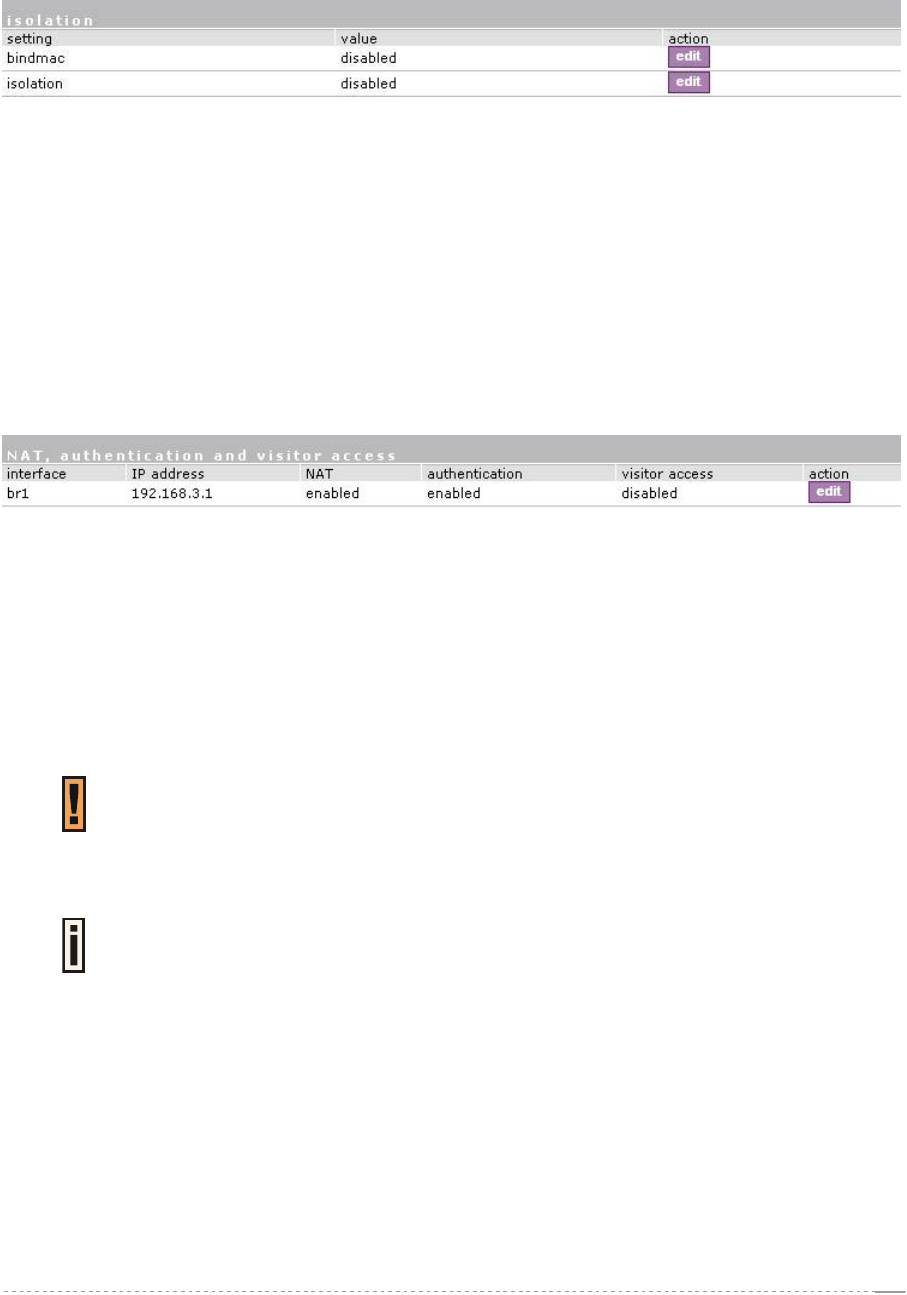
System | Access | Isolation
Isolation mechanism under the system | access | isolation menu increases the security of the AC
users.
Figure 186 – Isolation
Bindmac – with bindmac function enabled, the AC binds the user’s MAC and IP addresses together
after a successful logon by the wireless client and thereby preventing Internet access to a new user
who uses the same client IP address, although be it with a different MAC address [enabled/disabled].
Isolation – enable this function to prevent users on the same LAN to communicate with each other.
Users can communicate only through the AC [enabled/disabled].
System | Access | NAV
To change visitor access on different LANs or VLANs, authentication or NAT attributes for AC
users, go to the system | access | NAV menu:
Figure 187 – NAT, Authentication and Visitor Access
Interface – interface on which the changes will be done [br1, non editable].
IP Address – IP address of interface [non editable].
NAT – network address translation service status [enabled/disabled]. If enabled, users can access the
Internet under its network gateway address.
Authentication – with disabled authentication, the user from his LAN gets access to the Internet
without any authentication. If enabled, authentication for Internet access is required for all users
[enabled/disabled].
This setting is important when configuring the UAT. See section: System | Access
| UAT for more details.
Visitor Access – client with specific WISPr attribute can reach the LAN with enabled visitor access
[enabled/disabled].
Only one selected interface can have the visitor access enabled. Attempting to
enable an additional interface for visitor access will disable the previous interface.
System | Access | SNMP
SNMP is the standard protocol that regulates network management over the Internet. With enabled
SNMP service Wireless PAC can act as SNMP agent. To communicate with SNMP manager you
must set up the same SNMP communities and identifiers on both ends: manager and agent. For more
information about SNMP see Chapter 7 – SNMP Management.
Use the system | access | SNMP menu to enable/disable SNMP service or change current SNMP
configuration on your BW1330 controller.
BROWAN Page
106
User’s Guide Version 1.0
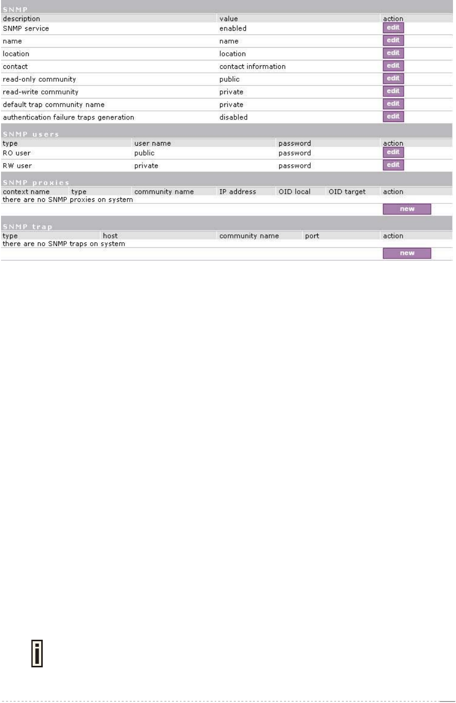
Figure 188– SNMP Settings
SNMP Table:
SNMP Service – enable or disable SNMP service on AC [enabled/disabled]. By default SNMP service
is enabled. With service enabled the AC acts as the SNMP agent.
If enabled, then device can be configured via SNMP:
SNMP Name – An administratively assigned name for this managed node [0-99 any string]. By
convention, this is the node’s fully qualified domain name.
SNMP Location – The physical location of this node (e.g., `telephone closet, 3rd floor') [0-99 any
string].
SNMP Contact – The textual identification of the contact person for this managed node, together with
information on how to contact this person [0-99 any string].
SNMP Read-Only Community – Community name is used in SNMP version 1 and version 2c. Read-
only (public) community allows reading values, but denies any attempt to change values [1-32 all
ASCII printable characters, no spaces].
SNMP Read-Write Community – Community name is used in SNMP version 1 and version 2c.
Read-write (private) community allows to read and (where possible) change values [1-32 all ASCII
printable characters, no spaces].
Default Trap Community Name – The default SNMP community name used for traps without
specified communities. The default community by most systems is "public". The community string
must match the community string used by the SNMP network management system (NMS) 1-32 all
ASCII printable characters, no spaces].
Authentication Failure Taps Generation – select [enable/disable] getting the authentication failure
traps from your AC.
SNMP Users Table:
SNMP Users table is only used for SNMP v3.
BROWAN Page
107
User’s Guide Version 1.0
SNMP Users – Users are used in SNMP version 3. They have the same access rights as
communities, but instead of a single community name there are user name and password. Strong
encryption is supported in SNMPv3.
Figure 189 –SNMP user
User Name – enter user name for read-only (RO) or read-write (RW) SNMP access [1-32 all ASCII
printable characters, no spaces].
Password – enter password for read-only (RO) or read-write (RW) SNMP access [8-32 all ASCII
characters, no spaces].
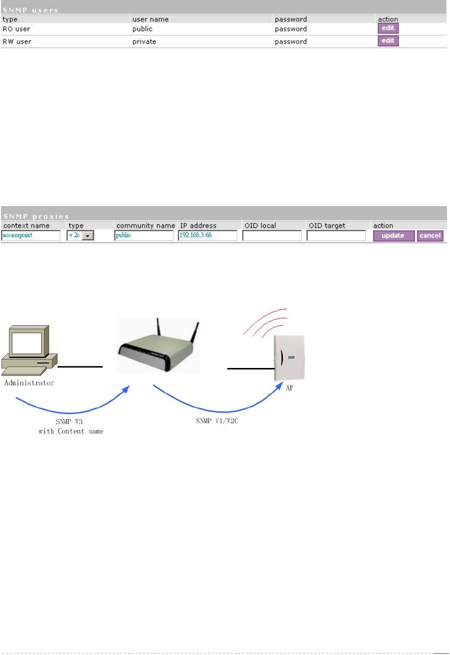
SNMP Proxies Table:
SNMP Proxies – SNMP proxy configuration specifies that any incoming SNMP requests can be send
to another host. SNMP proxy can be configured in such a way that can proxy only specified SNMP
request under specific OID (OID local). Click the new button to create SNMP proxy:
Figure 190 – Add SNMP Proxies
Context Name – enter the context name for SNMP proxy rule between client and AC. Context name
only works with SNMP v3. If a "context name" is specified, it assigns the proxy rule to a particular
context name within the local agent [1-32 all ASCII printable characters, no spaces]:
LAN
WAN
Figure 191– SNMP and Content Name
This is the proper way to query multiple SNMP agents through a single proxy. Assign each remote
agent to a different context name. Then you can use "snmpwalk -n contextname1" to walk one
remote proxied agent and "snmpwalk -n contextname2" to walk another, assuming you are using
SNMPv3 to talk to the proxy (snmpv1 and snmpv2c context mappings aren’t currently supported but
might be in the future) (see the Figure 191– SNMP and Content Name).
Type – select SNMP version for SNMP proxy rule between AP and AC [v1/v2c].
Community Name – enter community name for communicating with the host (see Figure 191– SNMP
and Content Name, the host is AP in this case) [1-32 all ASCII printable characters, no spaces].
IP Address – specify the host address (AP in our case) to which any incoming requests should be re-
sent [dots and digits].
OID Local – enter Object Identifier (OID) of MIB tree if you want to proxy only the specified SNMP
requests under the specific OID in the MIB tree. That part is specified by OID local tree [optional,
number and dots].
BROWAN Page
OID Target – Optionally, you can relocate the "OID local” tree to the new location at the "OID target"
108