GemTek Technology WIXB-175 WiMAX Indoor CPE User Manual CLWR IDU User Manual v1 3
Gemtek Technology Co., Ltd. WiMAX Indoor CPE CLWR IDU User Manual v1 3
UserManual.wiki
>
GemTek Technology
>
WIXB 175 User Manual
Manual
Navigation menu
Upload a User Manual
Namespaces
Wiki Guide
HTML
PDF
Info
Views
User Manual
Discussion / Help
Navigation
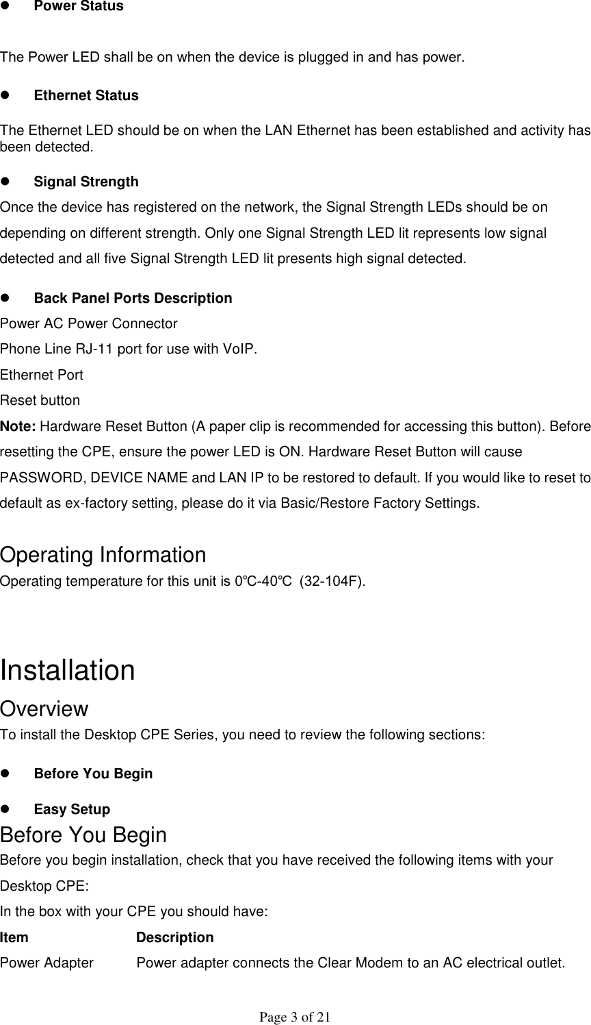
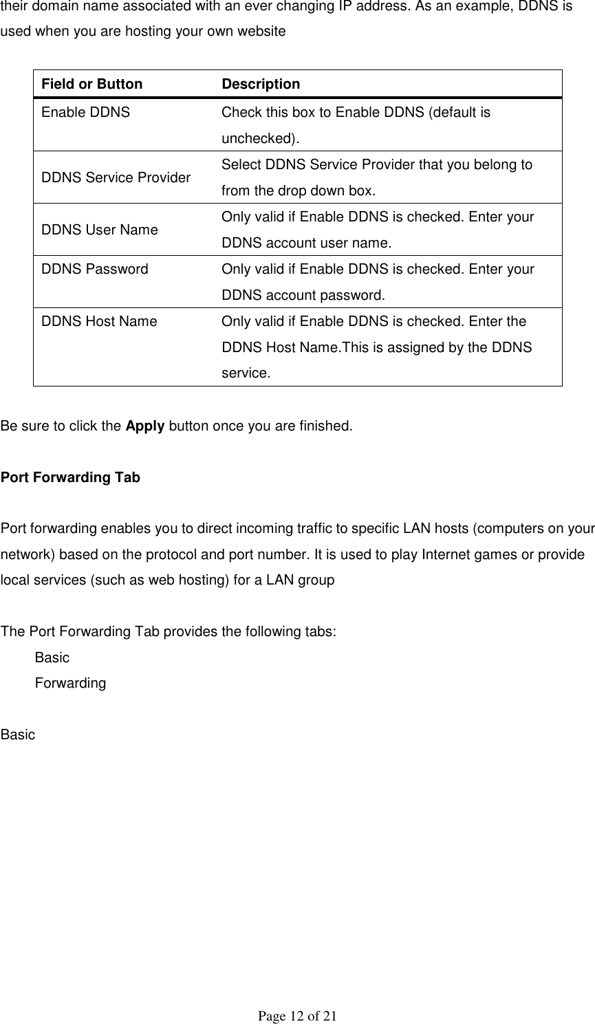
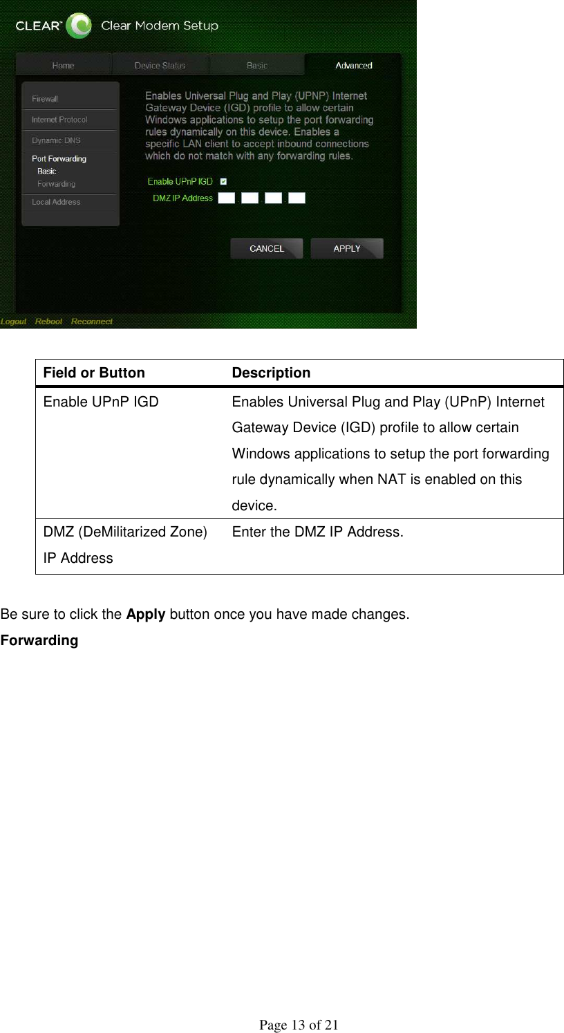
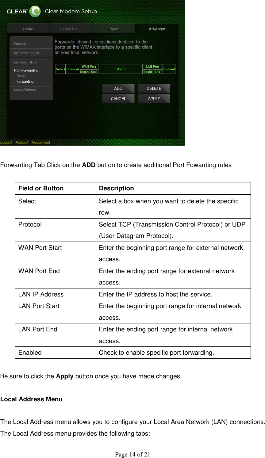
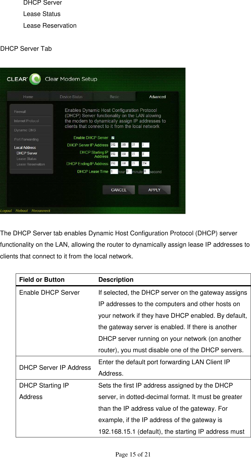
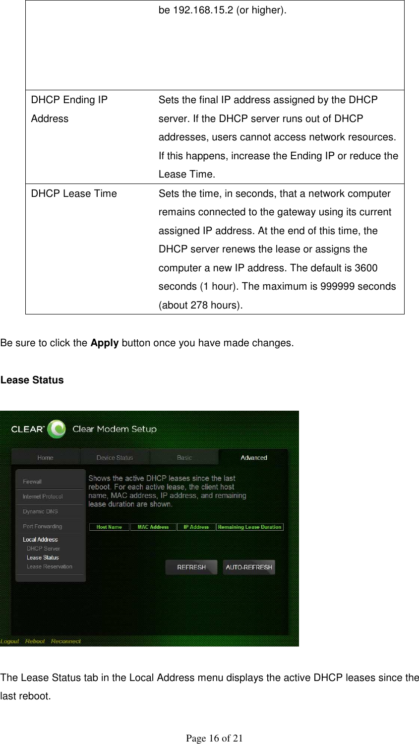
![Page 4 of 21 Ethernet Cable The Ethernet cable connects the Internet port on your Clear Modem to your PC or laptop computer. Clear Modem Quick Start Guide Provides quick installation instructions for getting your Desktop CPE up and running. Welcome Letter A brief introduction of the stuff inside the packaging and customer service contact window. Regulatory letter The FCC regulatory statement for this Clear Modem In addition, you will also need: A computer An RJ-11 telephone cable (optional, if you would like to use VoIP function). Easy Setup The CPE is easily set up in your home. Basic installation equipments needed are the power adapter, Ethernet cable and a PC or laptop computer and the CPE device. If you want to use the VoIP functionality, you will also need an RJ-11 phone cable and a telephone [external ATA is needed]. Perform the following tasks before powering up the unit: Stand the Clear Modem on a flat surface. Plug the power adapter into the power connector on the back of the unit. Plug the AC power cord into an AC outlet. The unit will turn on. Plug one end of the Ethernet cable into the Ethernet connector on the back of the unit. Plug the other end of the Ethernet cable into the Ethernet connector of your computer. To use VoIP functionality of the phone, plug one end of the phone line into the activated phone connector on the back of the unit. Phone line activation is dependent upon your service contract. Plug the other end of the phone line into the phone line connector of your telephone.](https://usermanual.wiki/GemTek-Technology/WIXB-175/User-Guide-1143034-Page-4.png)