GemTek Technology WL211P WLAN PCMCIA Card User Manual manual
Gemtek Technology Co., Ltd. WLAN PCMCIA Card manual
manual

Wi
re
l
ess
LAN
Use
r m
a
n
ua
l WL-211 P
C
Ca
r
d
P
age
1
User Manual
WL-211
PC Card
Version 1.0 – February 1999

Wi
re
l
ess
LAN
Page 2 WL
-
211 PC Card User manual
Federal Communication Commission Interference Statement
The information in this document is subject to change without notice and should not be construed as a
commitment by GemTek Technology Co., Ltd. GemTek Technology assumes no responsibility for any
error that may appear in this document.
GemTek is a registered trademark of GemTek Technology Co., Ltd.
The following are trademarked company and their names and products are used in this guide for
information purpose only.
PC Card is a trademark of PCMCIA
Windows is a trademark of Microsoft Corporation.
All the other trademarks and registered trademarks are the property of their respective owners.
INFORMATION TO USER
FCC REQUIREMENTS
This device complies with part 15 of the FCC Rules.
Operation is subject to the following two conditions:
(1) This device may not cause harmful interference, and
(2) This device must accept any interference received , including interference that may cause
undesired operation.
NOTE: This equipment has been tested and found to comply with the limits for a Class B digital device, pursuant to Part 15
of the FCC Rules. These limits are designed to provide reasonable protection against harmful interference in a residential
installation. This equipment generates, uses and can radiate radio frequency energy and, if not installed and used in
accordance with the instructions, may cause harmful interference to radio communications. However, there is no guarantee
that interference will not occur in a particular installation. If this equipment does cause harmful interference to radio or
television reception, which can be determined by turning the equipment off and on, the user is encouraged to try to correct
the interference by one or more of the following measures:
Reorient or relocate the receiving antenna.
Increase the separation between the equipment and receiver.
Connect the equipment into an outlet on a circuit different from that to which
the receiver is connected. consult the dealer or an experienced radio/TV
technician for help.
FCC Caution: To assure continued compliance, (example - use only shielded interface cables when
connecting to computer or peripheral devices). Any changes or modifications not expressly approved
by the party responsible for compliance could void the user's authority to operate this equipment.
Responsible Party: Synnex Co;LTD.
3797 Spinnaker Ct.
Fremont,CA 9453
Jim Nguyen
Fax No: 510-668-3602
Telephone No: 510-656-3333
Email Address : jimn@synnex.com

Wi
re
l
ess
LAN
Use
r m
a
n
ua
l WL-211 P
C
Ca
r
d
P
age
3
FCC Radiation Exposure Statement
This equipment complies with FCC radiation exposure limits set forth for an uncontrolled environment.
This equipment should be installed and operated with the minimum distance between your body and
the antenna as shown in the table below:
Integrated PCMCIA Antenna 20cm (7 inches)

Wi
re
l
ess
LAN
Page 4 WL
-
211 PC Card User manual
1. Contents
1 Contents ……………………………………………………………………………………………… 3
2 Introduction…………………………………………………………………………………………… 4
3 Wireless LAN Basics………………………………………………………………………………….6
4. Installation for Windows 95 (OSR2)/98………………….………………………………………….7
4.1 Installation Overview……………………………….……………………………………………8
4.2. Installation Procedure of WL-211 PC Card…………………………………………….……..9
5. Configuration Utilit …………………………………..………………………………………………11
6. Troubleshooting …….……………………………………………………………….………………18
7. Technical specifications of WL-211..………………………………………….……………………19

Wi
re
l
ess
LAN
Use
r m
a
n
ua
l WL-211 P
C
Ca
r
d
P
age
5
2. Introduction
Thank you for purchasing your Wireless LAN, WL-211 PC Card. This manual will assist you with the
installation procedure.
The package you have received should contain the following items:
• WL-211 PC Card
• User manual
• Diskette containing Wireless LAN Management utility and drivers
Note: if anything is missing, please contact your vendor
The diskette contains the drivers and the program Gtutil that is used for managing the WL-211 Card
and establishing the wireless connection with your Local Area Network.

Wi
re
l
ess
LAN
Page 6 WL
-
211 PC Card User manual
3. Wireless LAN Basics
Wireless LAN (Local Area Networks) systems offer a great number of advantages over a traditional,
wired system. Wireless LANs (WLANs) are more flexible, easier to setup and manage and often more
cost effective than their wired equivalence.
Using radio frequency (RF) technology, WLANs transmit and receive data over the air, minimizing the
need for wired connections. Thus, WLANs combine data connectivity with user mobility, and, through
simplified configuration, enable movable LANs.
With wireless LANs, users can access shared information without looking for a place to plug in and
network managers can set up or augment networks without installing or moving wires. Wireless LANs
offer the following productivity, convenience and cost advantages over traditional wired networks:
• Mobility - Wireless LAN systems can provide LAN users with access to real-time information
anywhere in their organization. This mobility supports productivity and service opportunities not
possible with wired networks.
• Installation Speed and Simplicity - Installing a wireless LAN system can be fast and easy and can
eliminate the need to pull cable through walls and ceilings.
• Installation Flexibility - Wireless technology allows the network to go where wires cannot go.
• Reduced Cost-of-Ownership - While the initial investment required for wireless LAN hardware
might be higher than the cost of wired LAN hardware, overall installation expenses and life-cycle
costs will be significantly lower. Long-term cost benefits are greatest in dynamic environments
requiring frequent moves, adds, and changes.
• Scalability - Wireless LAN systems can be configured in a variety of topologies to meet the needs
of specific applications and installations. Configurations are easily changed and range from peer-
to-peer networks suitable for a small number of users to full infrastructure networks of thousands
of users that allows roaming over a broad area.
Wi
re
l
ess
LAN
Use
r m
a
n
ua
l WL-211 P
C
Ca
r
d
P
age
7
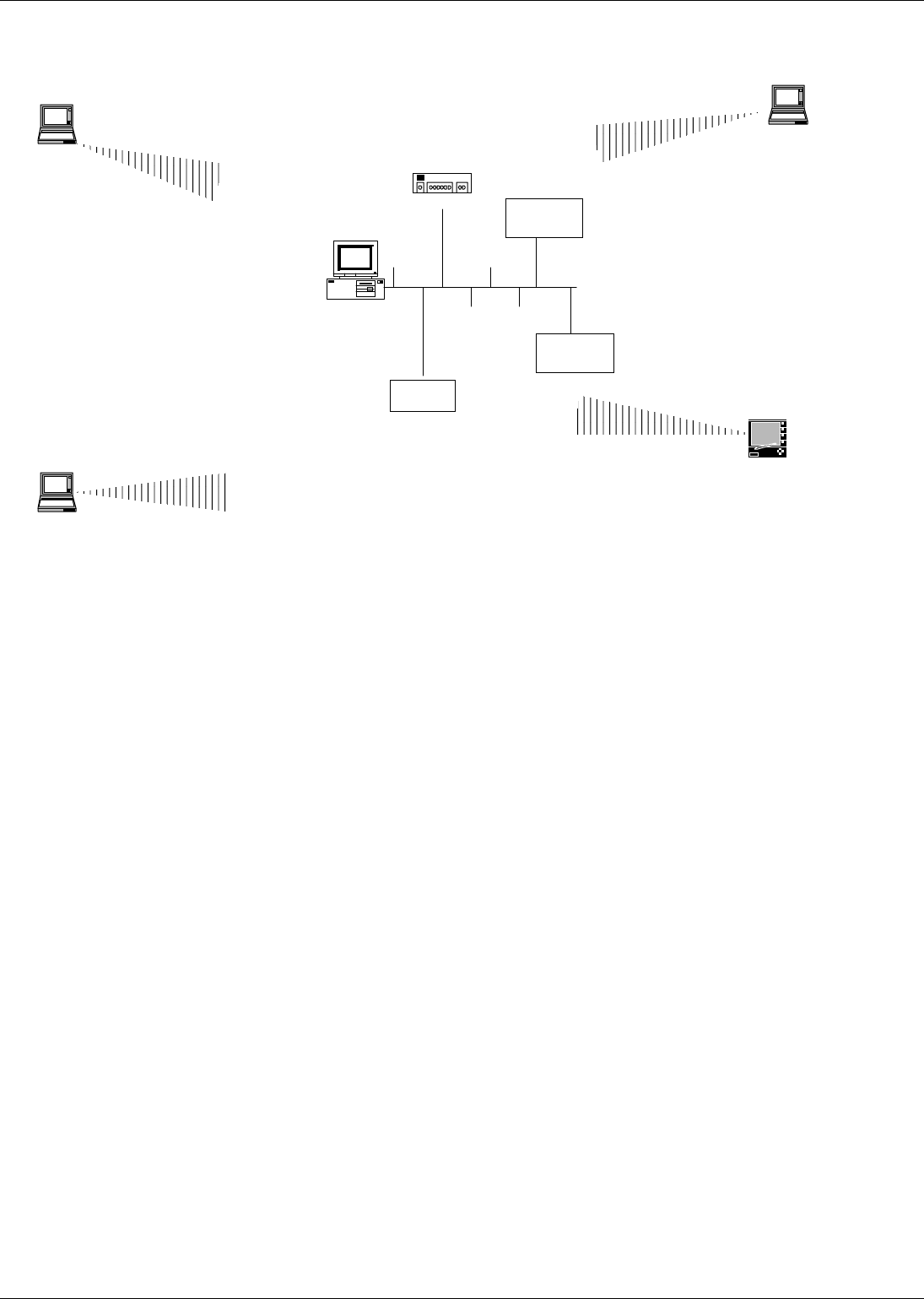
A P-1100
WINNT SERVER
WIN 2000
NT Workstation
WIN 98 Notebook
For PC Card
Hub
A P-550
WinC E
WX-1150
A ccess Point

Wi
re
l
ess
LAN
Page 8 WL
-
211 PC Card User manual
4. Installation for Windows 95 (OSR2)/98
The following section will assist you to in installing wireless LAN Adapter successfully. You will first
install software (driver) and then insert the WL-211 wireless LAN card, and finally set the network
properties to accommodate resource sharing and select the type of wireless network that you wish to
install. The WL-211 can easily be installed and used, without bothering to connect cables for keeping
your computer to use network resources, as in case of wired LAN.

Wi
re
l
ess
LAN
Use
r m
a
n
ua
l WL-211 P
C
Ca
r
d
P
age
9
4.1. Installation Overview
Here are some steps you will perform in establishing your wireless network connection:
! Install the Acess Point at first. AP is needed in case of Infrastructure network mode.
! Install the software using the Installation Diskette.
! Install the Wireless LAN Card (WL-211).
! Install the network protocol(s) required to communicate on your network. Most likely you will need
the TCP/IP protocol.

Wi
re
l
ess
LAN
Page 10 WL
-
211 PC Card User manual
4.2. Installation Procedure of WL-211 PC Card
Please follow the following steps one by one in order to install the PCMCIA card successfully.
1. Power on your computer and allow Windows 95 (OSR2)/98 to load fully.
2. Be sure that there is no PCMCIA adapter inserted yet.
3. Insert the given Installation Diskette and then click on the A:\disk1\ setup.exe.
4. Accept the license agreement.
5. Give the path of the destination folder. To set the path of your choice click on Browse and then click
Next.
6. It takes a few seconds for copying the utility files and then click on Finish to complete the
installation.
7. Insert the WL-211F card into PCMCIA slot , windows will then prompt the required driver
8. locate the driver path Ex. A:\ and install the driver
9. restart the PC and Click on the Control Panel and then on PC Card. Check whether it has PCMCIA
card in one of the sockets or not. If you find Gemtek IEE802.11PC Card in one of the sockets, it
means the card is detected properly.
10. Check for the GEMTEK 11Mbps Wireless PCMCIA LAN Card by right clicking on My Computer
using the mouse. Select the Device manager and then Network Adapters. If you find the Yellow (?)
sign on the adapter, it shows the installation is not successful. Select the adapter and click on
Remove. Restart your computer after uninstalling the driver to make the changes effective. And
refer to manual.
11. Right click on the Network Neighborhood using the mouse.
12. Select Properties from the pop up menu. The network box appears and you see three main tables:
Configuration, Identification, and Access Control.
13. Click on the Configuration tab and then click on the Add button. Select Network Component Type
box appears. Click on the Protocol the click the Add button.
14. Select Network Protocols box appears. From the list of manufactures, click on Microsoft. From the
list of network protocols list, select NetBEUI, then click OK.
15. The NetBEUI protocol is now installed. After clicking on OK return back to Network Component
Type box.
16. Repeat the step 15 and 16 to add IPX/SPX protocol.
17. Repeat the step 15 and 16 to add TCP/IP protocol.
Note: Do not insert the PCMCIA card until you are asked to do so, failure of which may result in unsuccessful installation
of your PCMCIA WLAN card

Wi
re
l
ess
LAN
Use
r m
a
n
ua
l WL-211 P
C
Ca
r
d
P
age
11
18. Click on the TCP/IP option for setting the IP address for your computer. You can select either Static
or DHCP setting. If you use the static IP setup then enter the IP value, Subnet masking , DNS,
Domain/ Workgroup name, and Gateway Address values. After setting these parameter
appropriately, click OK to return to Network Component Type and you can select the File and
Printer Sharing options as well as the Access to your computer bu other users connected to that
network by setting the computer sharing options. Click on OK.
19. Screen message do want to restart your Computer will pop up. Select Yes. It will shut down your
computer and will restart.
Proceed to chapter 5 for the explanation of the Configuration Utility.
Important: Restart your computer to make the changes effective before you reinstall the
driver.
Wi
re
l
ess
LAN
Page 12 WL
-
211 PC Card User manual
5. Configuration Utility
GemTek Inc PC Card Wireless LAN adapter (GemTek NIC) uses his own management software. All
functions controlled by user are provided by this application. Usually this application starts
automatically, Use Start, Programs, GemTek Wireless LAN to start the Manager application.
A new icon - should appear in your Icon tray. If the icon is marked with a red “X”, it means that
GemTek NIC configuration is invalid or incomplete. Sometimes icon can be colored in red. This can
happen when driver is in Pseudo BSS mode, and the radio channel, which is used for communication
is defined incorrectly.
Figure 1 Icon tray with a new icon
Figure 2: Error Icon
Double clicking on that icon will show you the screen as shown below.
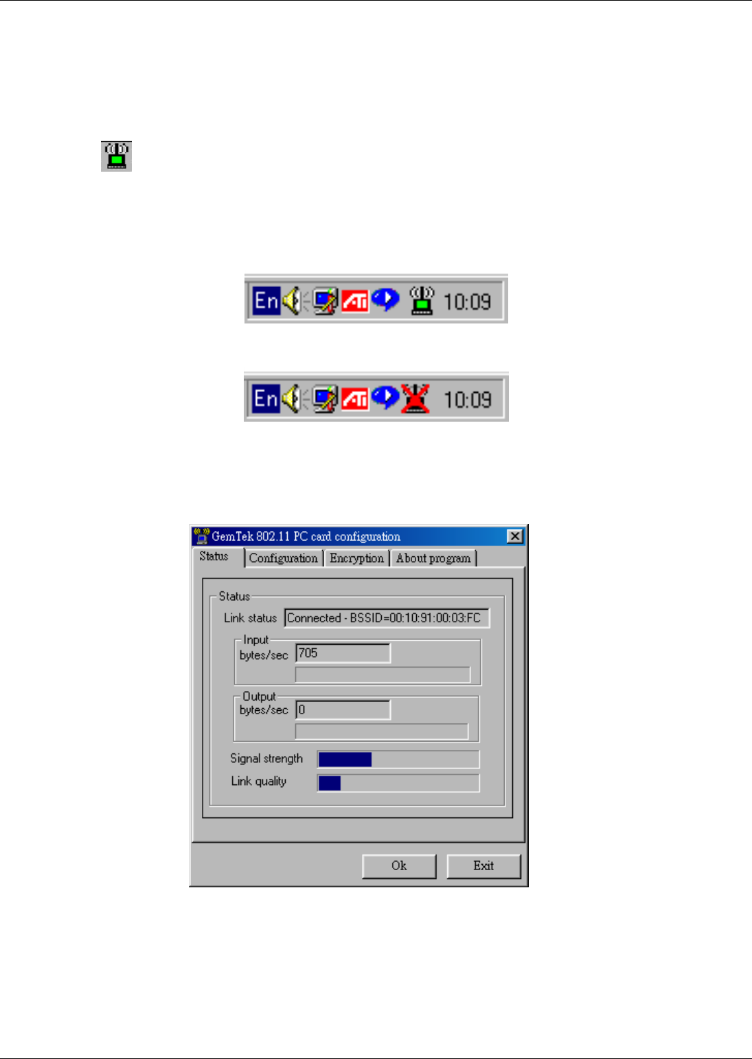
Figure 3 Management window with “Status” tab open
User can navigate through “sheets”, by clicking or tapping them with a stylus. “OK” button will minimize
window, and “Exit” (or X button) will close application. Here we explain the use and meanings of the
various screen messages.

Wi
re
l
ess
LAN
Use
r m
a
n
ua
l WL-211 P
C
Ca
r
d
P
age
1
3
The first three fields show your wireless network card state.
Link status – indicates link accesibility. There are several values, that can be shown in this part of the
window:
Connected - BSSID=… – normal flow of operation in Infrastructure mode. The PC is connected to
access point. BSSID is shown in the form of hex digits. Networking is available.
No status… - the manager is retrieving information from the driver. If this text box value stays more
than several seconds, it means that there are no access points or other workstations (if
communicating in AdHoc mode), or that the GemTek NIC card is plugged out of PC.
Scanning for access point – driver scans wireless network searching for available access point
in Infrastructure mode.
Disabled or disconnected - . If this text box value stays more than several seconds, it means that
there are no access points or other workstations (if communicating in Pseudo BSS mode), or
that the GemTek NIC card is plugged out of PC.
Undefined– means critical driver error. This error is usually caused by hardware misconfiguration
(for example the card with similar chipset inserted in PC card bay, but not fully compatible with
GemTek NIC).
Input bytes/sec – shows the incoming (received) data speed, the progress bar below, means receiver
load.
Output bytes/sec – shows the outgoing (sent) data speed, the progress bar below, shows transmitter
load.
Signal strength : bar shows signal strength level. The higher blue bar is, the more powerful is radio
signal received by Gemtek PC card. This indicator helps to find the most comfortable
antenna/workstation position for quality network operation.
Link quality: The measured signal level gives the overall Link Quality and Connection Status.
Wi
re
l
ess
LAN
Page 14 WL
-
211 PC Card User manual
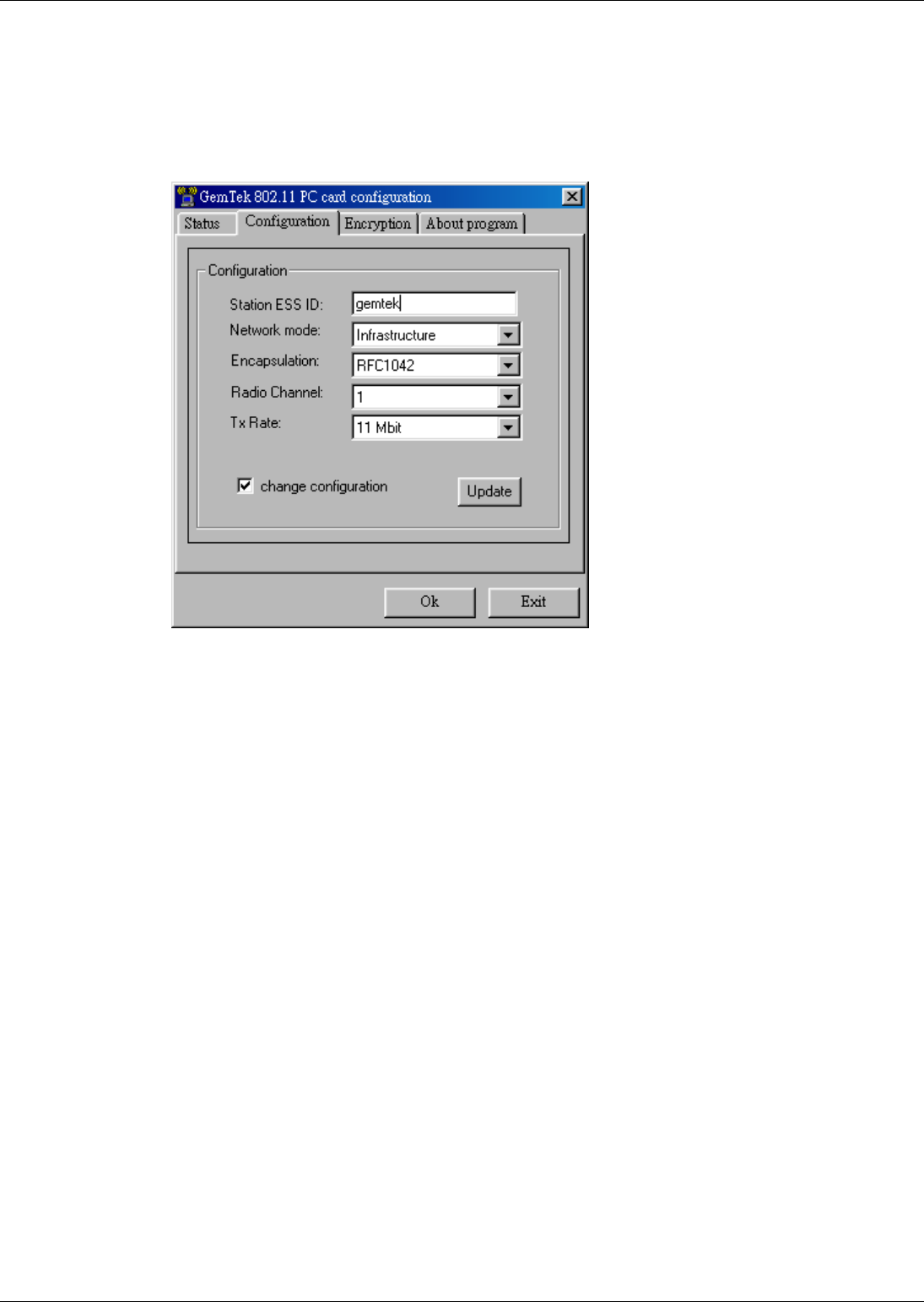
“CONFIGURATION” tab
You can change the configuration by clicking on the Change Configuration. When you click on the
Change Configuration, you see the screen given below.
Figure 4 Management window with "CONFIGURATION" tab open
Five changeable fields in this field show desired GemTek NIC configuration.
The fields are following:
Station ESS ID Extended Service Set Identifier (Wireless Network Identifier) is the group name that
will be shared by every member of your wireless network. You will only be able to connect with an
Access Point, which has the same ESS ID.
Network mode shows one of these network modes:
• Pseudo BSS -this is the 802.11 peer-to-peer mode of operation. In Ad Hoc only one wireless
"cell" is supported for each different ESS ID. All communication is done from Client to Client
without the use of an Access Point.
• Infrastructure This mode of operation requires the presence of an 802.11 Access Point. All
communication is done via the Access Point, which relays packets to other wireless Clients in
the BSS (Basic Service Set) as well as to nodes on a wired network such as Ethernet.

Wi
re
l
ess
LAN
Use
r m
a
n
ua
l WL-211 P
C
Ca
r
d
P
age
1
5
Encapsulation shows one of two different network packet forming modes
• None or Encapsulated This setting takes the entire Ethernet frame, including the Ethernet
Header, and puts it into an 802.11 frame. This setting is here for compatibility with some older
802.11 implementations and should not normally be used.
• RFC1042 where the DIX Ethernet frames are converted using SNAP header based on
RFC1042. This mode will also convert any RFC1042 SNAP header frames to DIX Ethernet
frames before transmission to the Ethernet interface.
• 802.1h where the DIX Ethernet frames are tunneled using a full selective translation table. This
mode does not convert RFC1042 SNAP header frames to DIX Ethernet before transmission to
the Ethernet interface
It is required to select encapsulation mode corresponding to the one your access point or other
workstations use. If the encapsulation mode is incorrect, the PC will join to access point or will
be seen by other workstations, but network operation will not work.
Channel – shows radio channel number used for networking. Only Access Points and Ad Hoc nodes
can create a BSS therefore this parameters is not active if Mode is Infrastructure. Infrastructure Client
nodes will always go the same channel as their AP. Please see the table for the requirements of
different countries and the channel frequency.
TX Rate: The transmission rate at which the data packets are transmitted by the client or AP. You can
set this to Auto select I or 2Mbps, Fixed 1 Mbps, Fixed 2 Mbps, Fixed 5.5 Mbps, Fixed 11 or Full Auto
(I to 11 Mbps).
Important: You must know the TX Rate that your AP can support. Failure to which may
cause the undesired results.
Wi
re
l
ess
LAN
Page 16 WL
-
211 PC Card User manual
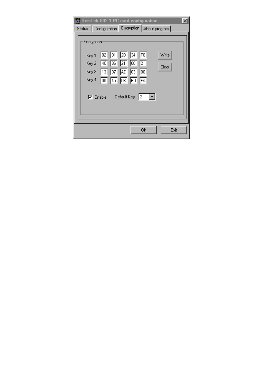
“ENCRYPTION” tab
Figure 5 Management window with “Encryption” tab open
You may desire an additional measure of security on your wireless network, which can be
achieved by using WEP (Wired Equivalent Privacy) encryption. WEP encrypts each frame
transmitted from the radio using one of the Keys entered from this panel.
When an encrypted frame is received it will only be accepted if it decrypts correctly. This will only
happen if the receiver has the WEP Key used by the transmitter.
This panel allows the entry of four keys, which can then be written to the driver and registry. Each
key must consist of hex digits, it means that only digit 0-9 and letters A-F are valid entries. If
entered incorrectly program will not write keys to a driver.
Key 1 – Key 4: These four fields must be used to enter the keys.
Write : This button updates the driver with the four keys displayed in Key1 through Key4. The keys
are also written to the registry for permanent storage.
Clear : This button clears all the bytes in the four keys, useful when entering and you wish to start
over.

Wi
re
l
ess
LAN
Use
r m
a
n
ua
l WL-211 P
C
Ca
r
d
P
age
17
Default Key : This pop-up field defines one of the four keys which will be used by the driver to
encrypt frames it will be transmitting. This field does not affect decryption, as the driver can
decrypt any frame that it receives which was encrypted with one of the four keys.
Enable : This checkbox enables or disables encryption operation. When it is checked, encryption
is enabled, and when unchecked – encryption is disabled. The corresponding action is written to a
driver immediately.
Wi
re
l
ess
LAN
Page 18 WL
-
211 PC Card User manual
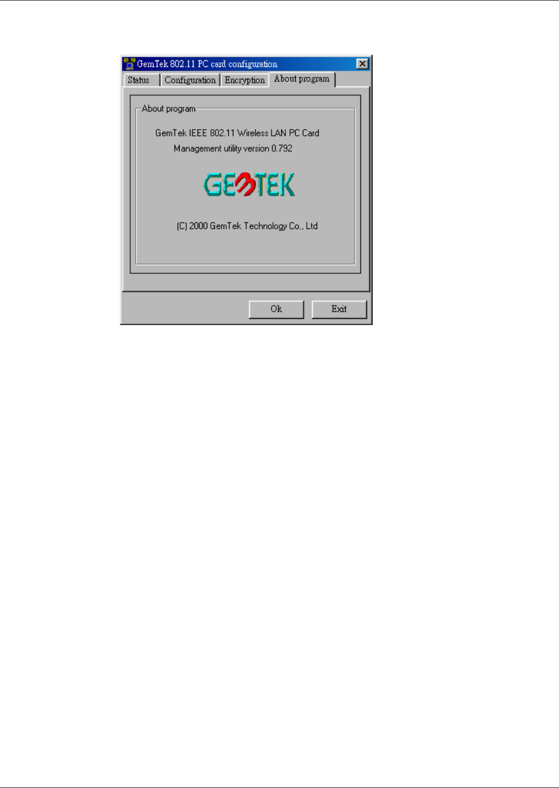
“ABOUT” tab
Figure 6 Management window with "ABOUT" tab open
About tab shows a software version. Users must use this version number when reporting their
problems to tech support.

Wi
re
l
ess
LAN
Use
r m
a
n
ua
l WL-211 P
C
Ca
r
d
P
age
1
9
6. Troubleshooting
To make the installation of Wireless LAN Card more users friendly, we have suggested following the
installation steps one by one as listed in the section 4 and section 5. Still you encounter some
problems while installing the WLAN Card or you want to confirm whether your card is installed properly
or not, we have listed the procedure for checking the various components after you have installed the
card. In first part of Troubleshooting, we have suggested the users to check the various properties of
the card to check the proper installation. In second section, we have listed the various problems that
you may encounter during the installation and have also listed the possible solution. Check the first
part to guess the probable reason of unsuccessful installation.
Procedure to Check the Various Properties of Card after Installation under Windows 95
(OSR2)/98:
Please check the followings if you encounter some problem while installing the PCMCIA card or your
PCMCIA card is non-functional.
1. Click on the Control Panel and then on PC Card. Check whether it has PCMCIA card in one
of the sockets or not. If you find GemTek IEEE 802.11 PC CARDd in one of the sockets, it
means the card is detected properly. If you see the Yellow sign of Question-mark (?), the
resources are conflicting.
2. Right click on My Computer and the select Properties. Select the Device Manager and click
on the Network Adapter. You will find GemTek IEEE 802.11 PC CARD if it is installed
successfully. If you see the Yellow sign the resources are conflicting. Click on PCMCIA Card
and then on PCMCIA Card Service, you can see the status of PCMCIA card. If there are yellow
sip either on adapter or PCMCIA card, please check the followings.
i) Check if your Notebook supports 3.3V Card.
ii) Check if your Notebook has a free IRQ. If not, make an IRQ free by assigning
the same IRQ to some devices, for example COM 1, COM 2 can be assigned same
IRQ values.
iii) Check that you have inserted the right card and have installed the proper driver.

Wi
re
l
ess
LAN
Page 20 WL
-
211 PC Card User manual
7. Technical specifications of WL-211
Hardware compatibility
− IBM-compatible computer with a PC Card Type II
Driver support
NDIS 3.1
− Windows 95 OSR2
− Windows 98
− Windows NT 4 and higher
− Linux
− WinCE(x86,SH4,MIPS)
Standards supported
− IEEE 802.11 standard for Wireless LAN
− All major networking standards (including TCP/IP, IPX)
Environmental
Operating temperature (ambient):
− -10°C to 50°C (Operating),-20 to 70°C (Storing)
− Max . Humidity:95% Non-condensing
Power specifications
Operating voltage:
− +5 V ,+3.3V DC ±5%
− Nominal Temp Range: 17 dBm
− Extended Temp Range: 14 dBm min.
− Transmit Power, 2.7v to 3v: 14 dBm min.
Radio specifications
Range:
− per cell indoors approx. 35-100 meters or more
− per cell outdoors up to 100-300 meters
Frequency range:
− 2.4-2.4835 GHz, direct sequence spread spectrum
Number of Channels:
− Europe: 13 (3 non-overlapping)
− US: 11 (3 non-overlapping)
− France: 4 (1 non-overlapping)
Antenna system:

Wi
re
l
ess
LAN
Use
r m
a
n
ua
l WL-211 P
C
Ca
r
d
P
age
21
− Internal patch antenna supporting diversity.
Mobility:
− Seamless roaming across cell boundaries with handover
Specific features
Supported bit rates:
− 11 Mbps
− 5.5 Mbps
− 1 Mbps
− 2 Mbps
Data encryption:
− 40 bit WEP Encryption, 128-bit key length optional
Utility Software:
− Link Config™ User setup & diagnostics tool
Key Management:
− Automatic Dynamic Key Allocation (ADKA) through public key
Physical Dimensions
− Extended type-II PC Card 110 x 54 x 6 mm
− Weight 3

Wi
re
l
ess
LAN
Page 22 WL
-
211 PC Card User manual