GemTek Technology WLTFQR121GN LTE router User Manual
Gemtek Technology Co., Ltd. LTE router
Contents
- 1. User manual (statement)
- 2. User manual
User manual

WLTFQR-121 | User Manual
Copyright
This DOCUMENT is copyrighted with all rights reserved. No part of this publication may be
reproduced, transmitted, transcribed, stored in a retrieval system, or translated into any
language in any form by any means without the written permission of Gemtek Technology
Co. Ltd.
Notice
Gemtek reserves the right to change specifications without prior notice.
While the information in this document has been compiled with great care, it may not be
deemed an assurance of product characteristics. Gemtek shall be liable only to the degree
specified in the terms of sale and delivery.
The reproduction and distribution of the documentation and software supplied with this
product and the use of its contents is subject to written authorization from Gemtek.

LTE Indoor CPE | User Manual P. 2
Content
Copyright ................................................................................................................................ 1
Notice ....................................................................................................................................... 1
About this Guide .................................................................................................................. 4
Prerequisite Skills and Knowledge...................................................................................... 4
Conventions Used in this Document .................................................................................. 4
Introduction ........................................................................................................................... 5
Product Overview ............................................................................................................... 5
Product Package ................................................................................................................. 5
Connectors ......................................................................................................................... 6
LED Indicators ..................................................................................................................... 7
Installation .......................................................................................................................... 8
Web Interface ...................................................................................................................... 12
Icon Indicator ...................................................................................................................... 14
Reference Manual .............................................................................................................. 15
Mobile Network ............................................................................................................... 17
Mobile Network | Status .......................................................................................... 17
Mobile Network | Technology.................................................................................. 18
Mobile Network | PIN .............................................................................................. 19
Mobile Network | Default PDN ................................................................................ 20
Network ............................................................................................................................ 22
Network | Status ...................................................................................................... 22
Network | Network Mode ........................................................................................ 23
Network | DHCP Server ............................................................................................ 24
Network | QoS .......................................................................................................... 26
Network | Port Forwarding ...................................................................................... 27
Network | Port Trigger ............................................................................................. 28
Network | Dynamic DNS .......................................................................................... 29
Network | MGMT Service ........................................................................................ 30
WiFi ................................................................................................................................... 31
WiFi | Status ............................................................................................................. 31
WiFi | Settings .......................................................................................................... 32
Firewall ............................................................................................................................. 36
Firewall | Basic ......................................................................................................... 36
Firewall | L3 MGMT Filter ........................................................................................ 38
Firewall | L3 DATA Filter ........................................................................................... 39
Firewall | L2 Filter ..................................................................................................... 40
Firewall | Access Restriction .................................................................................... 41
Management .................................................................................................................... 42
Management | Account ........................................................................................... 42

LTE Indoor CPE | User Manual P. 3
Management | Language ......................................................................................... 43
Management | Device Setting ................................................................................. 44
Management | Restore Default ............................................................................... 45
Management | Software .......................................................................................... 46
Management | RM Settings ..................................................................................... 48
Monitoring ........................................................................................................................ 49
Monitoring | Status .................................................................................................. 49
Monitoring | Iperf .................................................................................................... 50
Monitoring | Diagnostic Tools .................................................................................. 50
About ................................................................................................................................ 51
About | Status .......................................................................................................... 51

LTE Indoor CPE | User Manual P. 4
About this Guide
This document provides information and procedures on installation and configuration of
Gemtek LTE Indoor CPE. You could utilize the theoretical information in this guide to setup
your device.
Prerequisite Skills and Knowledge
To use this document effectively, you should have a working knowledge of Local Area
Networking (LAN) concepts and wireless Internet access infrastructures. In addition, you
should be familiar with the following:
Hardware installers should have a working knowledge of basic electronics and
mechanical assembly, and should understand related local building codes.
Network administrators should have a solid understanding of software installation
procedures for network operating system and troubleshooting knowledge. LTE Indoor
CPE has a web GUI which supports http/https protocol; it could be used to configure the
CPE settings through web browser by your PC. Please refer to following pages for more
detail.
Conventions Used in this Document
The following typographic conventions and symbols are used throughout this document:
Very important information. Failure to observe this may result in
damage.
Important information that should be observed.
Additional information that may be helpful but which is not required.
bold
Menu commands, buttons and input fields are displayed in bold

LTE Indoor CPE | User Manual P. 5
Introduction
Product Overview
LTE Indoor CPE is an all-in-one device that integrates FDD-LTE and Wi-Fi service.
Support FDD-LTE
Support 3GPP Release 9 compliant
Support LTE UE Category 4
Support 2 LAN ports
Support HTTP/HTTPS Web GUI
Product Package
Item
Qty
1
LTE Indoor CPE
1
2
User Manual
1
3
Power Adapter
1
4
RJ-45 Ethernet cable
1
If any items of mentioned above are missing or damaged, please
contact our customer support immediately.
LTE Indoor CPE | User Manual P. 6
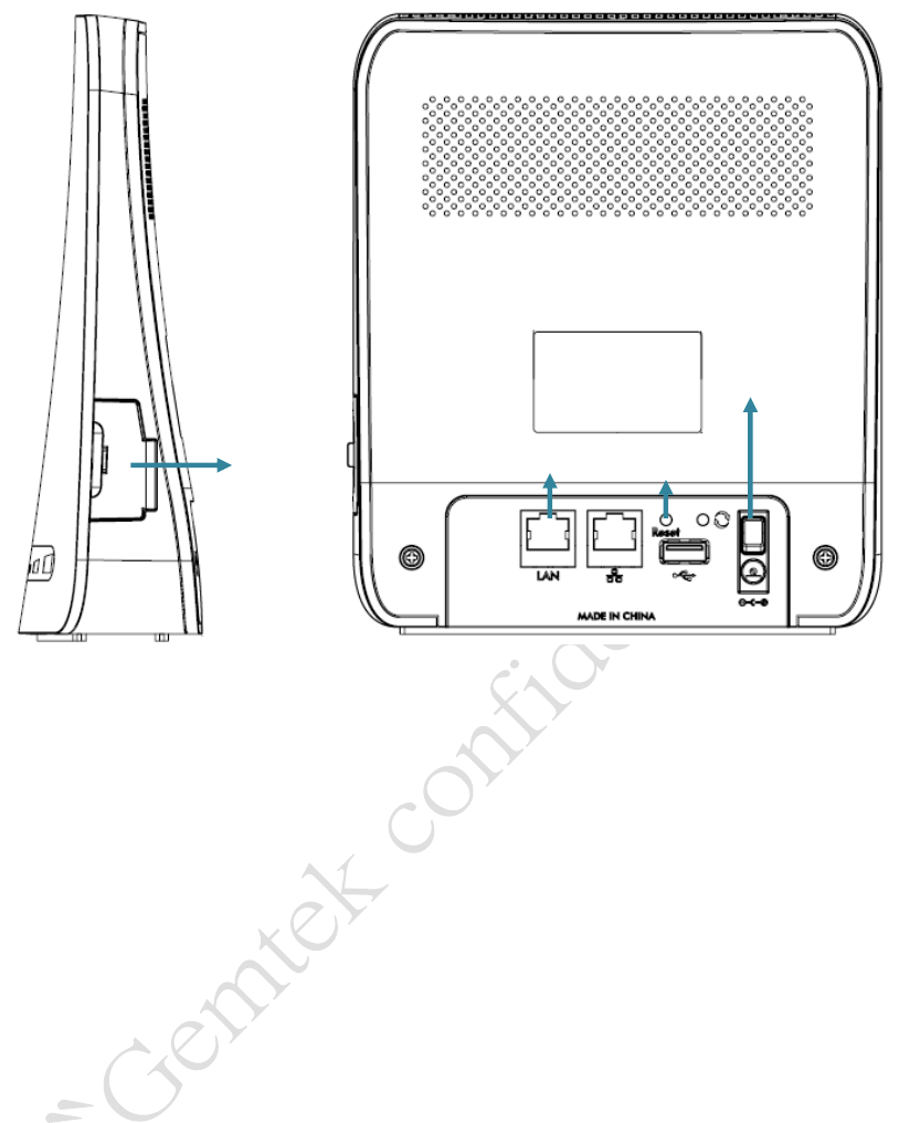
Connectors
LTE Indoor CPE Connectors
1. SIM card slot: Insert SIM card into the slot with right direction.
2. Reset Button: Use a pin to press “Reset” button for less than 5 seconds to reboot the
device. Or press and hold the Reset button for more than 10 seconds to set the device
to factory default settings.
3. LAN Port (RJ-45): This port is for connecting LTE Indoor CPE to your PC or other
network equipments (such as hubs or switches) with a RJ-45 Ethernet cable.
4. DC-12V Port (Power Adapter Socket): Connect the power adapter provided with LTE
Indoor CPE.
LTE Indoor CPE | User Manual P. 7
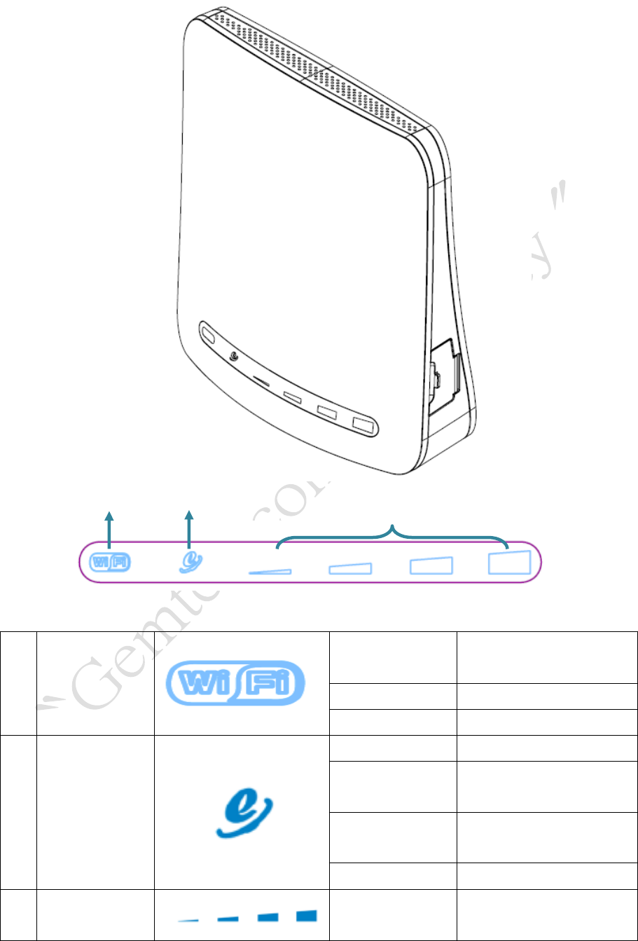
LED Indicators
IDU LED Indicators
1
Power & WiFi
Red
Power on (system boot
up)
Blue
WiFi Enabled
Fast Blinking
WiFi Transmitting data
2
2G/3G/4G
Fast Blinking
Connecting
Blinking every 2
seconds
2G connected
Blinking every 1
second
3G connected
ON
4Gconnected
3
Signal Strength
4 level strength
meter
Display signal strength
LTE Indoor CPE | User Manual P. 8
Installation
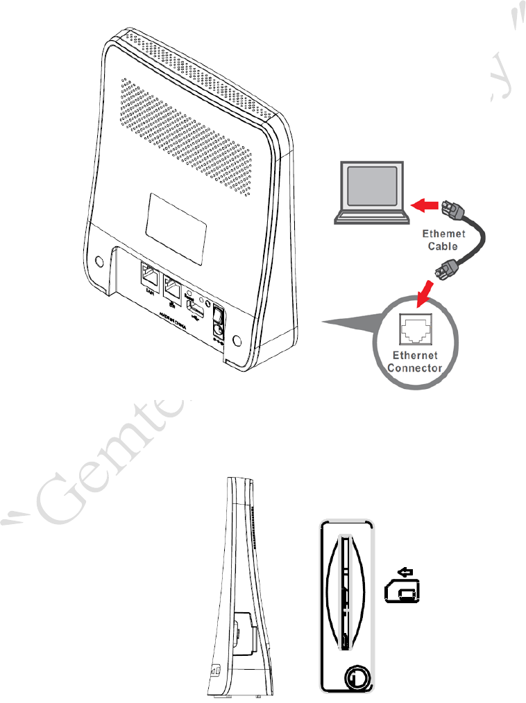
Please follow the steps below to install the device:
Step1: Place your LTE Indoor CPE on a flat work surface.
Step2: Connect the device LAN port to your PC with a RJ-45 Ethernet cable that is
supplied.
Step3: Insert SIM card into the device with right direction.
LTE Indoor CPE | User Manual P. 9
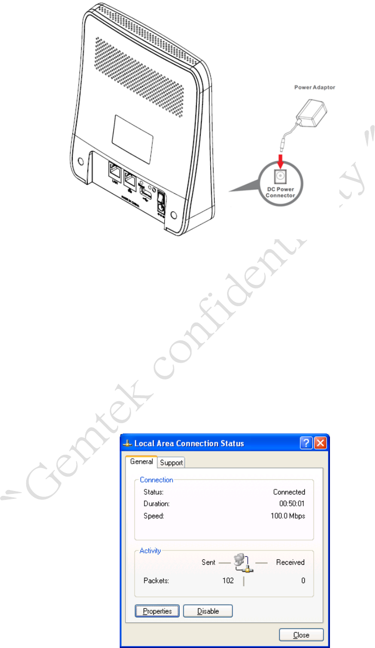
Step4: Insert the power cord into the LTE Indoor CPE's DC-12V power jack; and then
insert the plug into power outlet.
Step5: The device will start the booting process once the power has been connected.
Please wait for a minute to let the booting process complete.
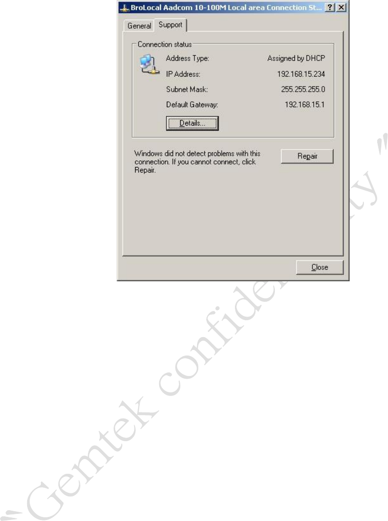
Step6: Select Local Area Connection Status from Windows task bar and click
Properties.
Local Area Connection Status
LTE Indoor CPE | User Manual P. 10
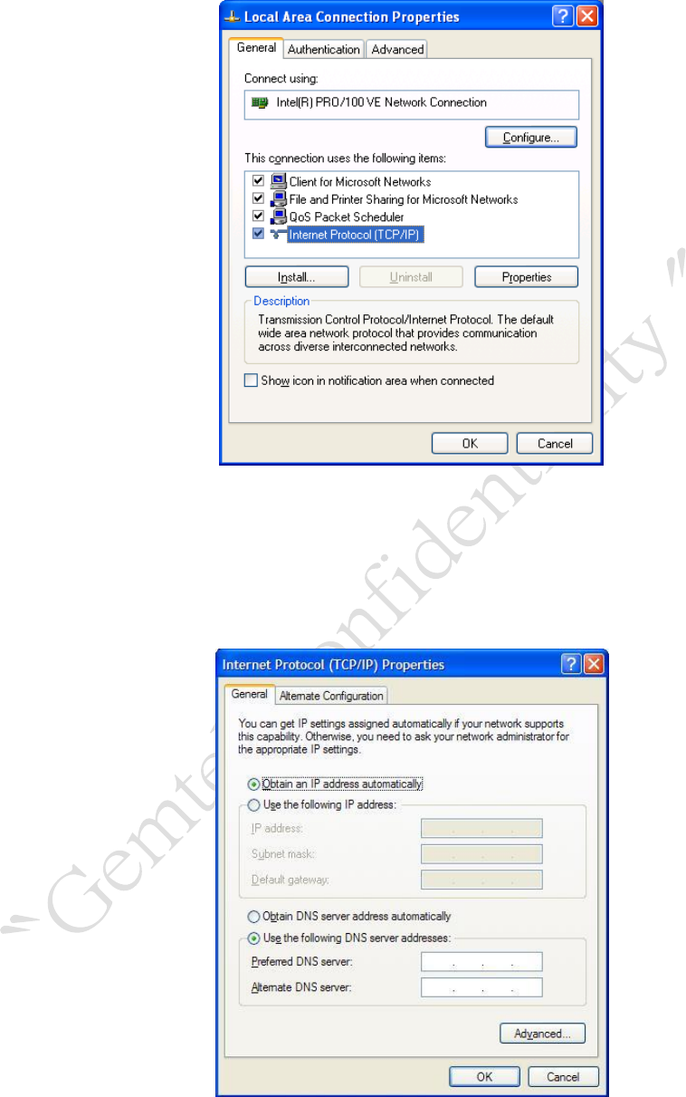
Step7: Double click on the Internet Protocol (TCP/IP).
Local Area Connection Properties
Step8: Select Obtain an IP address automatically and click OK.
Internet Protocol (TCP/IP) Properties
LTE Indoor CPE | User Manual P. 11
Step9: By now, the device should have got IP address from your DHCP server.
Step10: How to verify CPE has a successful connection to the LTE eNodeB? This can be
verified by observing the signal strength LEDs (Please refer LED Indications
section in Introduction chapter of this manual to find the location of these
LEDs on the device). At least one of these LEDs glowing continuously is an
indication of successful connection to the eNodeB. Now you can start
browsing the Internet.
LTE Indoor CPE | User Manual P. 12
Web Interface
Please follow the steps below to configure your device through the web interface:
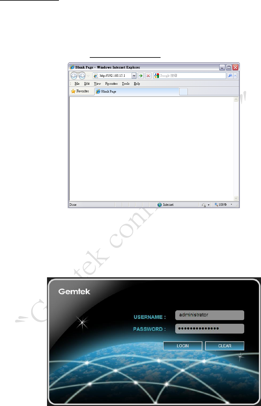
Step1: Open the Web browser (Internet Explorer) and enter the default IP address of the
IDU CPE, which is: http://192.168.15.1
Web browser
Step2: Enter IDU administrator login username/password to access the web
management interface.
The default username / password is administrator/administrator.
Web management interface
LTE Indoor CPE | User Manual P. 13
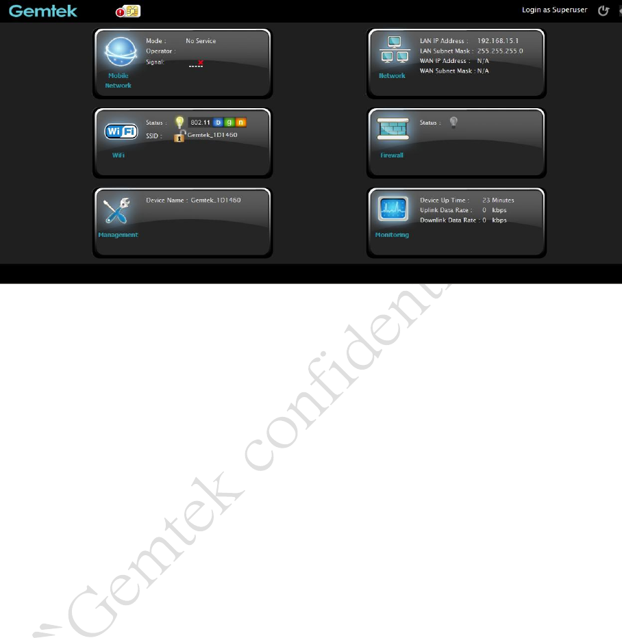
Step3: The page shown here gets displayed in your browser after login; you can now
configure the device settings.
GUI Interface
LTE Indoor CPE | User Manual P. 14
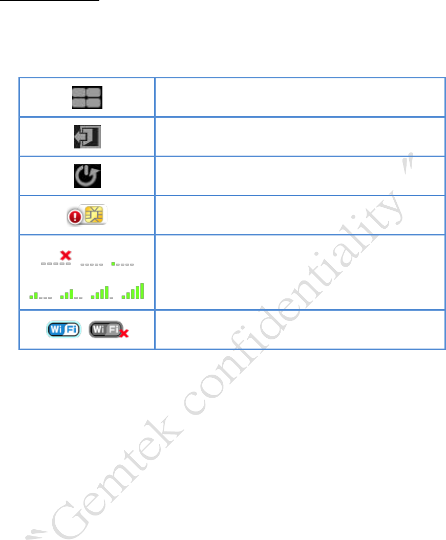
Icon Indicator
In the upper side of GUI interface, there is a banner contains lots of different icons which
indicate different meanings. Users can refer to below table for further explanation.
Press this button to get back to “Home” screen.
Press this button to log out from GUI.
Press this button to reboot the CPE.
Please insert SIM card.
Signal strength status. The more bars showed, the
better signal strength.
WiFi Enabled / Disabled.
LTE Indoor CPE | User Manual P. 15
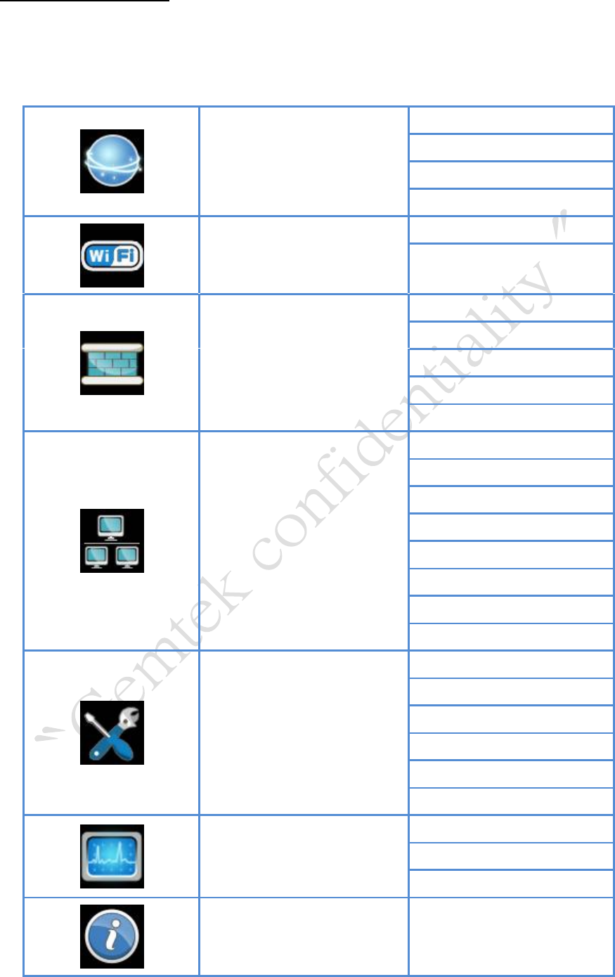
Reference Manual
The main menu is located at the center of the screen and each main menu item contains
sub-items. You can refer to the menu structure which is given below:
Mobile Network
Status
Technology
PIN
Default PDN
WiFi
Status
Settings
Firewall
Basic
L3 MGMT Filter
L3 DATA Filter
L2 Filter
Access Restriction
Network
Status
Network Mode
DHCP Server
QoS
Port Forwarding
Port Trigger
Dynamic DNS
MGMT Service
Management
Account
Language
Device Setting
Restore Default
Software
RM Settings
Monitoring
Status
Iperf
Diagnostic Tools
About
Status

LTE Indoor CPE | User Manual P. 16
Menu Structure Table
LTE Indoor CPE | User Manual P. 17
Mobile Network
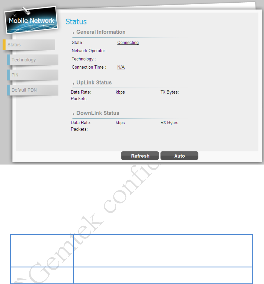
Mobile Network | Status
Mobile Network > Status
This page is to display the LTE connection status. When LTE Indoor CPE connects to eNodeB,
you can view related LTE connection status.
Refresh button
Click the “Refresh” button to receive the latest LTE
connection status.
Auto button
This button will update the status information periodically.
LTE Indoor CPE | User Manual P. 18
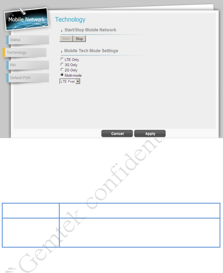
Mobile Network | Technology
Status > Technology
This page is designed for you to start/stop mobile network and you can choose which mobile
tech mode settings you want.
Cancel button
Reset fields to the last saved values.
Apply button
Commit the changes made and save to the CPE device, some
services will be reloaded.
LTE Indoor CPE | User Manual P. 19
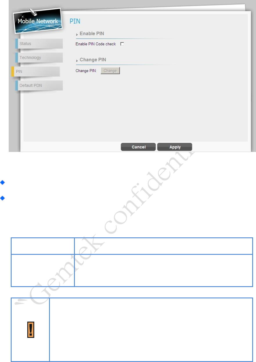
Mobile Network | PIN
Status > PIN
Enable PIN: Tick the checkbox and click “Apply” button to enable PIN protection.
Change PIN: Enter old PIN code, new PIN code, and confirm PIN code; and then click
“Apply” button to apply the change you’ve made.
Cancel button
Reset fields to the last saved values.
Apply button
Commit the changes made and save to the device, new
settings will be reloaded.
If you enter the wrong PIN more than three times (the maximum
numbers of attempts allowed), your SIM card will become
“PUK-locked” status. Please contact your service provider for further
unlock instruction.
LTE Indoor CPE | User Manual P. 20
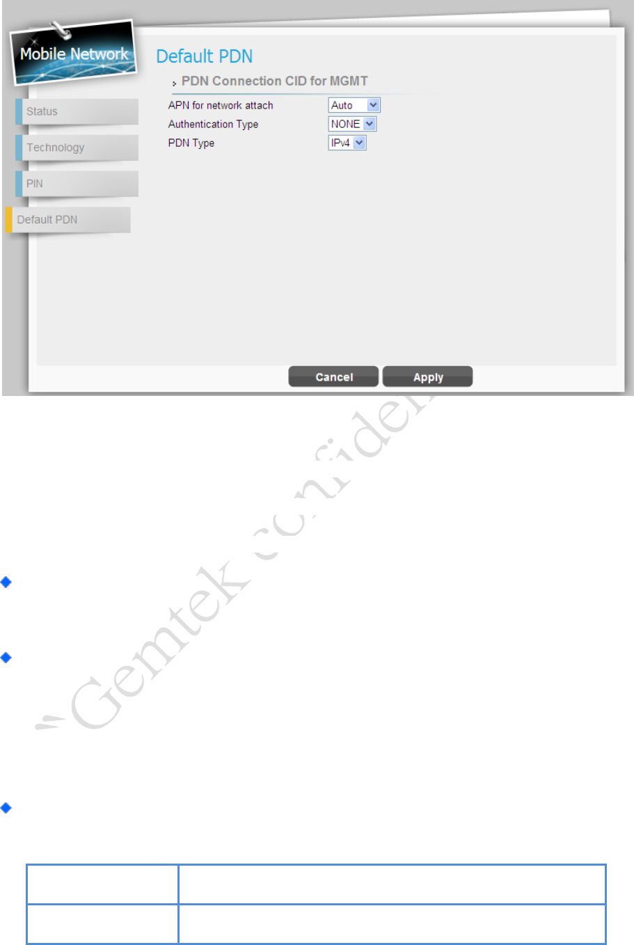
Mobile Network | Default PDN
Status > Default PDN
Packet Data Network (PDN) Gateway is responsible for acting as an anchor of mobility
between 3GPP and non-3GPP technologies. It provides connectivity from the device to
external packet data networks by being the point of exit and entry of traffic for the device.
APN for network attach: Select “Auto” to let CPE to automatically capture APN from
your service provider or “Manual” to manually type APN name in “APN” field.
Authentication Type: Select authentication type for APN from drop-down list;
“None”, “PAP (Password authentication protocol)”, or “CHAP (Challenge
Handshake Authentication Protocol)”. Enter the corresponding username and
password in below fields if PAP or CHAP is selected.
PDN Type: Only “IPv4” available at this moment.
Cancel button
Reset fields to the last saved values.
Apply button
Commit the changes made and save to the device, new

LTE Indoor CPE | User Manual P. 21
settings will be reloaded.
LTE Indoor CPE | User Manual P. 22
Network
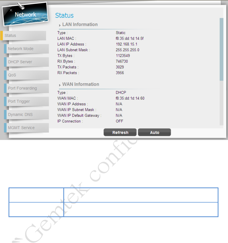
Network | Status
Network > Status
This page is to display the status of CPE such as LAN/WAN and lease status/information.
Refresh button
Click the “Refresh” button to receive the latest device status.
Auto button
This button will update the status information periodically.
LTE Indoor CPE | User Manual P. 23
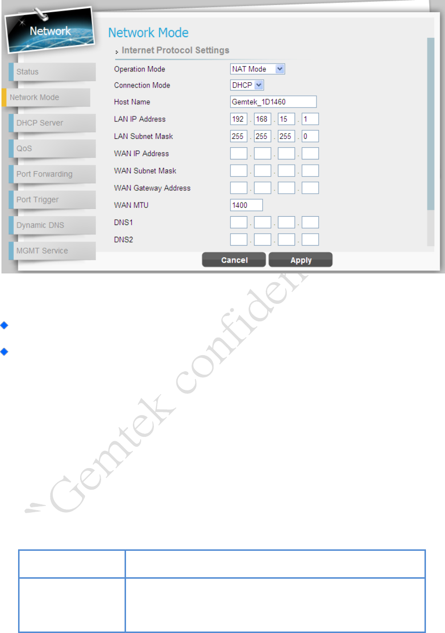
Network | Network Mode
Network > Network Mode
Operation Mode: Only NAT Mode is available at this moment.
Connection Mode: There are two connection mode provided from the CPE, “DHCP” or
“Static”.
If “DHCP” mode is selected, CPE would automatically acquire configuration
information from a DHCP server and uses it to configure its host; enter the host
name in “Host Name” field. If successfully get the IP information from DHCP server,
they will be shown on each field with grey font.
Static IP addresses are manually assigned to a device by an administrator; if
“Static” mode is selected, manually enter required information in below fields.
Cancel button
Reset fields to the last saved values.
Apply button
Commit the changes made and save to the CPE device, some
services will be reloaded.
LTE Indoor CPE | User Manual P. 24
Network | DHCP Server
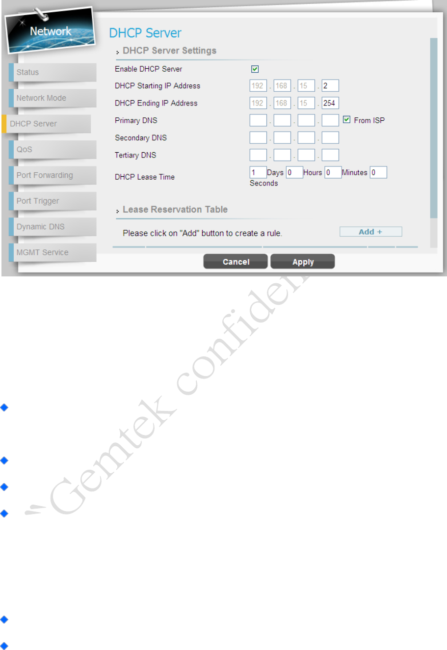
Network > DHCP Server
This device has a built-in DHCP server that can be used for managing the distribution of IP
addresses for the devices connected to the local Ethernet ports and WiFi access point. In the
DHCP Server page you could set DHCP parameters for dynamic IP assignment.
Enable DHCP Server: Tick the checkbox dynamically assign a leased IP address to
clients that connect to the device from the local network.
DHCP Starting IP Address: Enter the first IP address assigned by the DHCP server.
DHCP Ending IP Address: Enter the last IP address assigned by the DHCP server.
Primary/Secondary/Tertiary DNS: You can specify three DNS server and select
how the DNS Server is assigned. Tick the checkbox “From ISP” to gain the DNS
server from ISP; the below three DNS fields will be disabled. If un-tick the checkbox,
enter the DNS server IP by yourself.
DHCP Lease Time: Set the lifetime for your DHCP IP. (Range: 2minutes~365days)
Lease Reservation Table: This table displays information on reserved IP addresses
for leasing. In this section you can assign the specific IP addresses to the specific client

LTE Indoor CPE | User Manual P. 25
device connected to the Ethernet ports and WiFi access point. Click “Add+” button to
add a reserved IP for leasing.
Host Name - Enter a name to the host
MAC Address - Add a device MAC address
IP Address - Specify a reservation IP address for a specified MAC address
Enabled – Tick/un-tick the checkbox to enable or disable a specified IP setting
Delete - Select an IP to delete
Add button
Click the “Add+” button to add a new rule setting.
Cancel button
Reset fields to the last saved values.
Apply button
Commit the changes made and save to the CPE device, some
services will be reloaded.
LTE Indoor CPE | User Manual P. 26
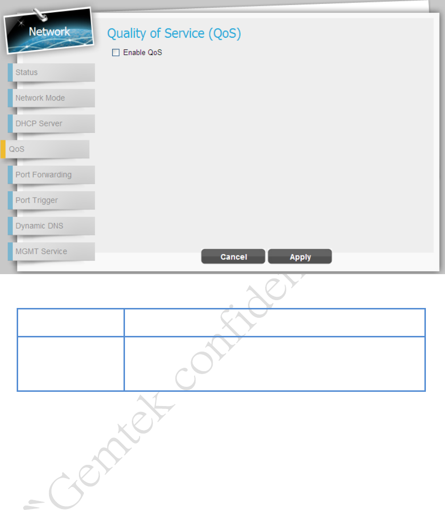
Network | QoS
Network > QoS
Cancel button
Reset fields to the last saved values.
Apply button
Commit the changes made and save to the CPE device, some
services will be reloaded.
LTE Indoor CPE | User Manual P. 27
Network | Port Forwarding
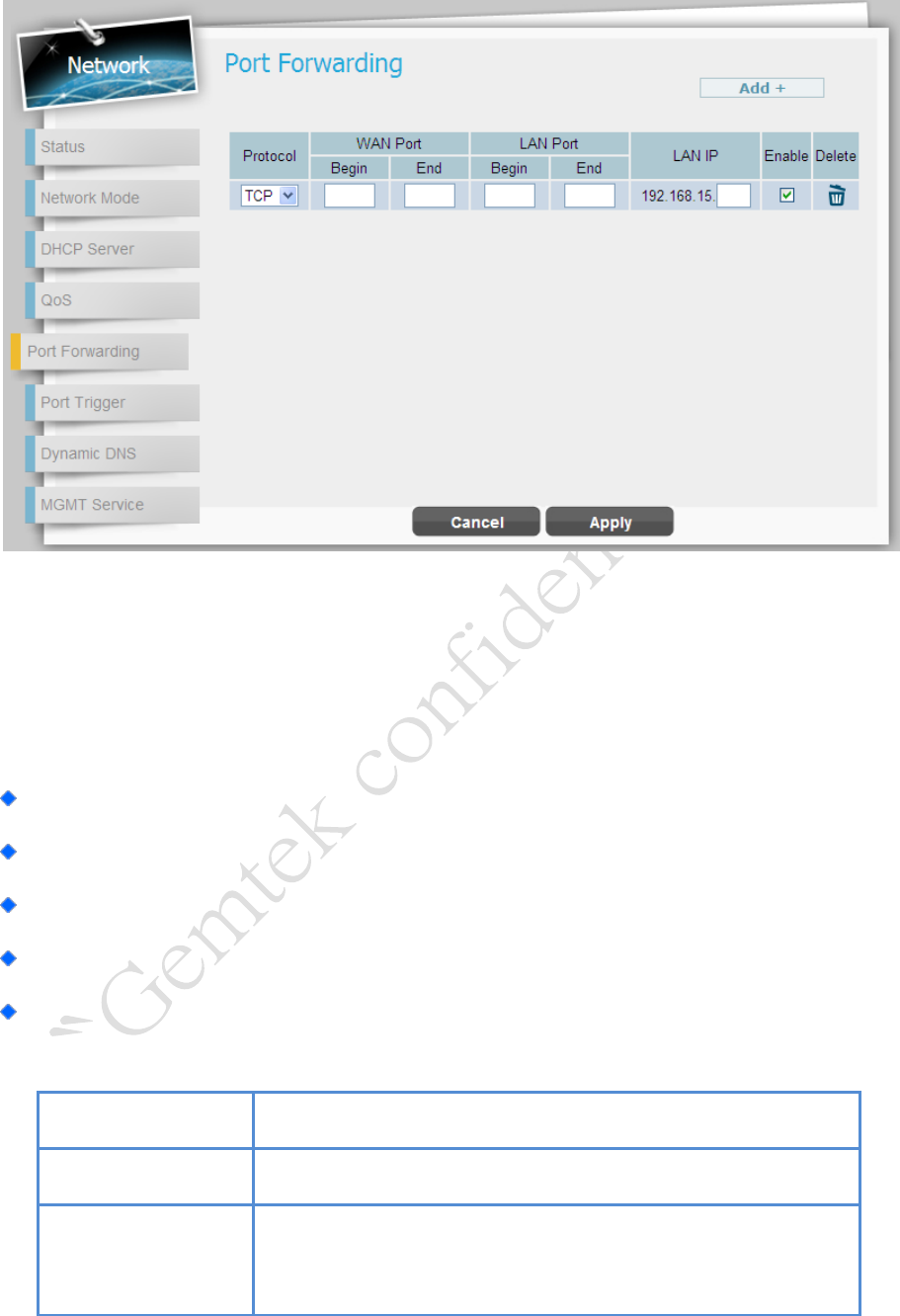
Network > Port Forwarding
Port Forwarding forwards the packet according to the routing table from WAN port to a
designated IP port. This Port Forwarding page enables managing and setup of the rules for
Port Forwarding. Click “Add+” button to add a new port forwarding rule.
Protocol: Set the protocol for port forwarding: TCP or UDP
WAN Port: Enter the range (begin and end ports) for the WAN
LAN IP: Enter the IP address that identifies the IP subnet of the remote network
Enabled: Select this check-box to enable/disable port forwarding for the specific IP
Delete: Select an IP to delete
Add button
Click the “Add+” button to add a new rule setting.
Cancel button
Reset fields to the last saved values.
Apply button
Commit the changes made and save to the CPE device, some
services will be reloaded.
LTE Indoor CPE | User Manual P. 28
Network | Port Trigger
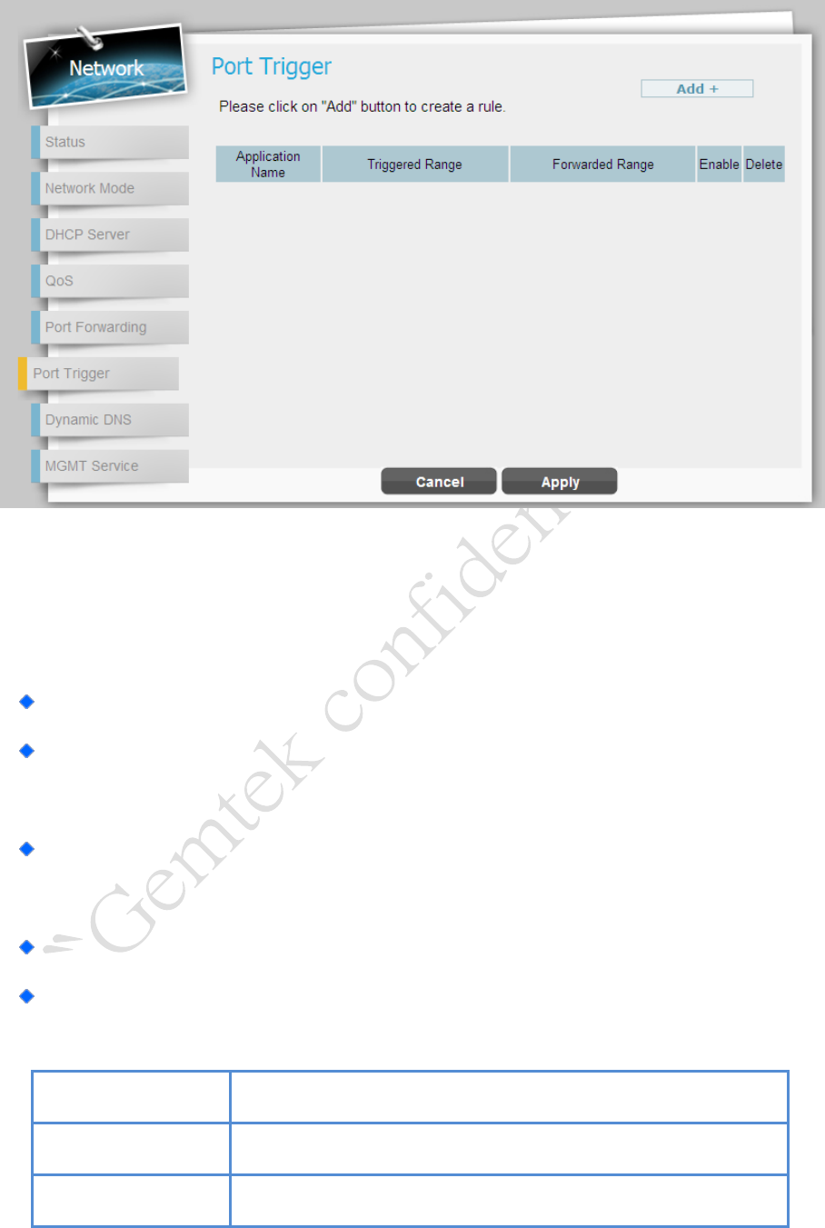
Network > Port Trigger
The tab allows you to configure Port Trigger rules; click the “Add+” button to add a new
Port Trigger rule.
Application Name: Name of the Port Trigger rule.
Triggered Range: Which port range the outgoing packet will trigger the rule? Enter
the starting and ending port range.
Forwarded Range: Which port range the incoming packet will trigger the rule?
Enter the starting and ending port range.
Enable: Tick the checkbox to active the rule.
Delete: Select a rule to delete.
Add button
Click the “Add+” button to add a new rule setting.
Cancel button
Reset fields to the last saved values.
Apply button
Commit the changes made and save to the CPE device, some
LTE Indoor CPE | User Manual P. 29
services will be reloaded.
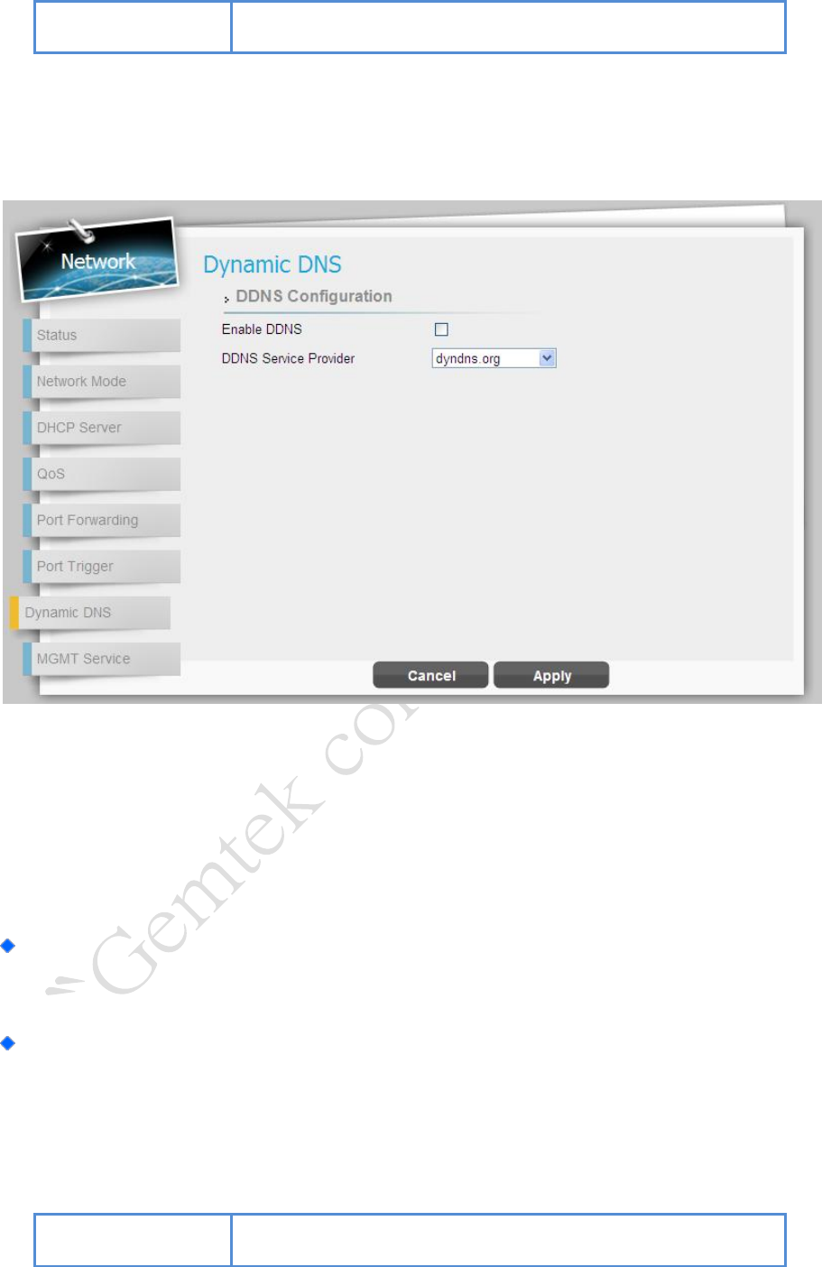
Network | Dynamic DNS
Network > Dynamic DNS
Dynamic Domain Name System (DNS) is a mechanism used to map a domain name to the
dynamic IP address of a network device. This page allows enabling the Dynamic DNS and
selecting the service provider.
Enable DDNS: Tick the checkbox if the unit has a non-static IP address to keep the
domain name associated with an ever-changing IP address.
When DDNS is enabled, select the DDNS service provider you registered from the
drop-down list, and configure the following parameters: DDNS Service Provider, DDNS
User Name, DDNS Password, and DDNS Host Name.
Cancel button
Reset fields to the last saved values.
LTE Indoor CPE | User Manual P. 30
Apply button
Commit the changes made and save to the CPE device, some
services will be reloaded.
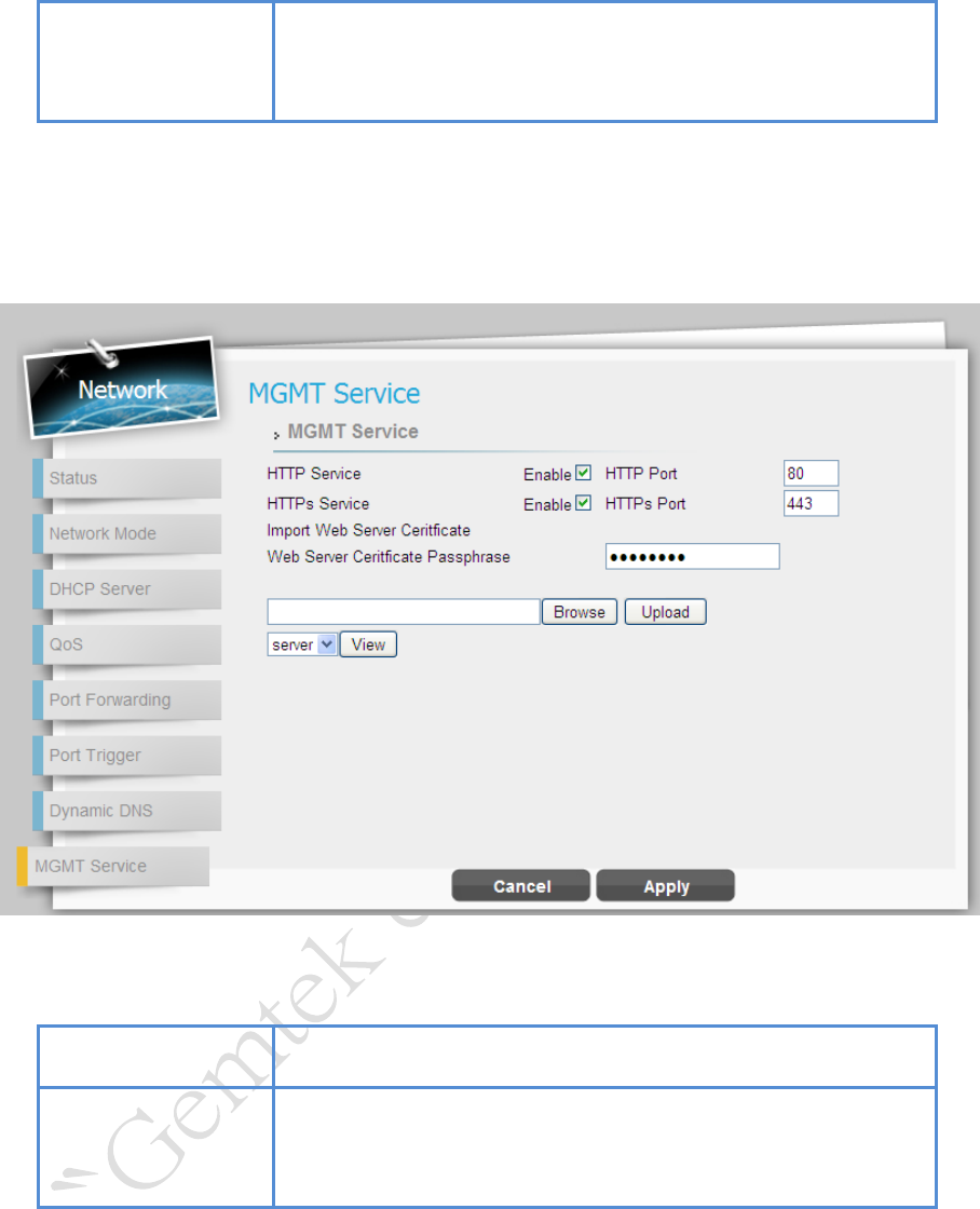
Network | MGMT Service
Network > MGMT Service
Cancel button
Reset fields to the last saved values.
Apply button
Commit the changes made and save to the CPE device, some
services will be reloaded.
LTE Indoor CPE | User Manual P. 31
WiFi
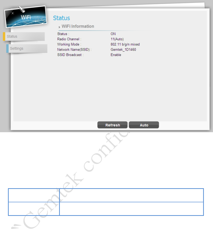
WiFi | Status
WiFi > Status
This page is to display the information of WiFi, such as status, radio channel, working mode,
network name (SSID) and SSID broadcast.
Refresh button
Click the “Refresh” button to receive the latest device status.
Auto button
This button will update the status information periodically.
LTE Indoor CPE | User Manual P. 32
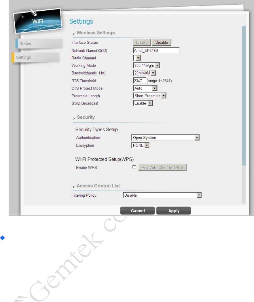
WiFi | Settings
WiFi > Settings
Wireless Settings
Interface Status: Click “Disable” button to disable WiFi, or click “Enable” to
activate WiFi function.
Network Name (SSID): SSID (service set identifier) is a function performed by
an device transmits its name so that wireless stations searching for a network
connection can 'discover' it; the default value is “Airtel_EF819B”.
Radio Channel: Select wireless channel from Channel 1 to 11. “Auto” will allow
CPE to choose the best channel automatically.
Working Mode: Select the wireless protocol as you desired: “802.11b/g/n”,
“802.11b/g”, “802.11g/n”, “802.11b”, “802.11g”, or “802.11n”.
Bandwidth(Only 11n): The setting is only available when wireless protocol

LTE Indoor CPE | User Manual P. 33
802.11n is applied; select the bandwidth as required from the drop-down list.
• 20M – Setting the bandwidth to 20M.
• 20M/40M – The bandwidth setting will automatically be switched between
20M and 40M by CPE.
RTS Threshold: RTS (Request-to-send) packets are a mechanism used by the
802.11 wireless networking protocols which establish an open communication to
an AP or node; it is a signal sent from the transmitting station to the receiving
station requesting permission to transmit. The range of RTS threshold is from 256
to 2432.
CTS Protect Mode: Clear to send (CTS) protection mode is a wireless setting that
ensures computers on a network can connect to a wireless router when many
communications devices are present. When the setting is “Always On”, a computer
must receive a CTS frame from the wireless access point (WAP) before
information can be sent. An “Auto” setting determines which computer can reach
a WAP at a specific through a request to send (RTS) packet. If CTS Protect Mode
is “Always Off”, network computers may experience difficulty in reaching the
Internet as they all try to connect at the same time.
Preamble Length: The preamble is the first part of the Physical Layer
Convergence Protocol/Procedure (PLCP) Protocol Data Unit (PDU); a length of null
signal before data. It gives time for receivers on the network to detect the signal
and prepare to receive the data. Short preamble takes less time to process and
minimizes overhead, so it should be used in a good wireless network environment
when all wireless clients support it; select “Long” if you have a 'noisy' network
environment which long preamble could provide more reliable communication.
SSID Broadcast: Having SSID broadcast disabled essentially makes your device
invisible unless a wireless client already knows the SSID, or is using tools that
monitor associated clients. The default setting of SSID Broadcast is “Enabled”.

LTE Indoor CPE | User Manual P. 34
Security
Security Types Setup: There are 8 different security types provided as below;
select the authentication method and encryption you need, and then enter
correspondent information into followed setting fields.
Authentication
Encryption
Open Systems
None
802.1x
WEP
802.1x Settings -
Rekey Interval
RADIUS Server
RADIUS Port
RADIUS Key
WEP Auto
WEP
Static Key Settings -
Default Key
Key
WPA2-Personal
TKIP
AES
TKIP/AES
Pre-shared Settings -
Rekey Interval
Key Pass Phrase
WPA-Personal
TKIP
AES
TKIP/AES
Pre-shared Settings -
Rekey Interval
Key Pass Phrase
WPA/WPA2-Personal
Mixed Mode
TKIP
AES
TKIP/AES
Pre-shared Settings -
Rekey Interval
Key Pass Phrase
WPA2-Enterprise
TKIP
AES
TKIP/AES
802.1x Settings -
Rekey Interval:
RADIUS Server
RADIUS Port
RADIUS Key
WPA-Enterprise
TKIP
AES
TKIP/AES
802.1x Settings -
Rekey Interval:
RADIUS Server
RADIUS Port
RADIUS Key
WPA/WPA2-Enterprise
Mixed Mode
TKIP
AES
802.1x Settings -
Rekey Interval:
LTE Indoor CPE | User Manual P. 35
TKIP/AES
RADIUS Server
RADIUS Port
RADIUS Key
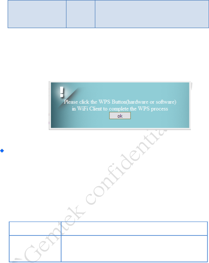
Enable WPS: When “Open Systems” authentication is selected; a WPS(Wi-Fi
Protected Setup) function is available. Tick the checkbox to enable WPS, click
“Add WiFi Client by WPS” button on GUI to add another client to be connected
to the CPE.
Access Control List: This option could allow you to control the access to wireless
network from specific MAC address. Select “Disable” to disable this function, or select
“Allow” / “Deny” to add a new rule for access permission/restraint. Click “Insert”,
and then enter the MAC address no matter you would like to allow or prevent the
specific wireless connection.
Cancel button
Reset fields to the last saved values.
Apply button
Commit the changes made and save to the CPE device, some
services will be reloaded.
LTE Indoor CPE | User Manual P. 36
Firewall
The Firewall page enables to configure the firewall feature. The firewall feature can be used
to block unauthorized access while allowing only authorized communications from the
Internet network. This feature also allows the device to be managed over the Internet by
authorized personnel.
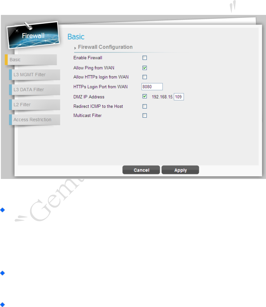
Firewall | Basic
Firewall > Basic
Lan Interface Status: Click “Enable” button to enable two physical Ethernet (RJ-45)
ports, and vice versa, “Disable” button would make two physical Ethernet ports
invalid. No matter LAN interface is enabled or disabled, users could use WiFi connection
to log in to GUI.
Enable Firewall: Tick the checkbox to enable firewall which means set the default
access policy to “deny”.
Allow ping from WAN: Tick the checkbox to enables the unit to respond to ping

LTE Indoor CPE | User Manual P. 37
commands for troubleshooting purposes.
Allow HTTPs login from WAN: Tick this checkbox to access the device from other
networks. When web login is enabled and a port is defined, you can access the device
from another network simply by opening a browser and entering the address of the
device. Please be noted that enable this function may have some unauthorized access
from external networks. Available only if HTTPs Service is enabled in Network | MGMT
Service.
HTTPs Login Port from WAN: Define a specific port number for security access
control. Available only if HTTPs Login from WAN is enabled.
DMZ IP Address: Set a server that acts as a "neutral zone" (DMZ stands for
"Demilitarized Zone") and separates an internal network from a public one in order to
prevent outside access to private data. The DMZ forwards the network traffic to specific
IP.
Multicast Filter: This setting allows multicast traffic to be forwarded to the
appropriate destination. Tick the checkbox to disable multicast packets to be
forwarded to the appropriate destination via CPE.
Cancel button
Reset fields to the last saved values.
Apply button
Commit the changes made and save to the CPE device, some
services will be reloaded.
LTE Indoor CPE | User Manual P. 38
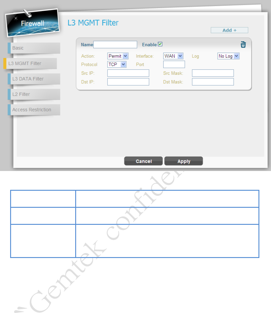
Firewall | L3 MGMT Filter
Firewall > L3 MGMT Filter
Add button
Click the “Add+” button to add a new rule setting.
Cancel button
Reset fields to the last saved values.
Apply button
Commit the changes made and save to the CPE device, some
services will be reloaded.
LTE Indoor CPE | User Manual P. 39
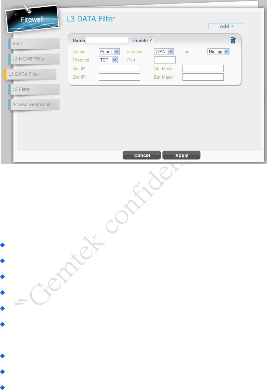
Firewall | L3 DATA Filter
Firewall > L3 DATA Filter
L3 DATA Filter could help you to set up the firewall rules to manage the network
transmission no matter it is inbound or outbound traffic between computers inside LAN and
WAN.
Click “Add+” button to add a new rule or click the “Trash Can” icon to delete the rule.
Select: Tick the checkbox to edit the rule, or click “Del” button to delete a specific rule.
Name: Enter the name of the rule.
Enable: Tick the checkbox to enable the rule.
Action: Select “Permit” or “Deny” to allow the access of the traffic or reject the traffic.
Interface: Select which interface you required to block/allow the traffic from;
available options are “WAN”, “LAN”, or “BOTH”.
Log: Select “Log” to have log records, or “No Log” to disable it.
Protocol: Protocol to filter on; available options are TCP, UDP, ICMP, or ANY.
Port: Enter port number to filter on.
LTE Indoor CPE | User Manual P. 40
Src IP: Enter the source IP to filter on.
Dst IP: Enter the destination IP to filter on.
Src Mask: Enter the source Mask to filter on.
Dst Mask: Enter the destination Mask to filter on.
Add button
Click the “Add+” button to add a new rule setting.
Cancel button
Reset fields to the last saved values.
Apply button
Commit the changes made and save to the CPE device, some
services will be reloaded.
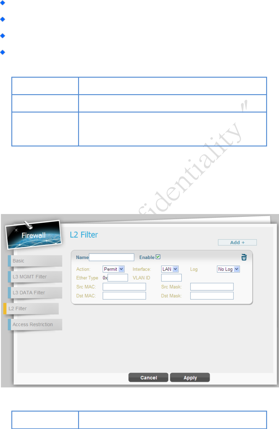
Firewall | L2 Filter
Firewall > L2 Filter
Add button
Click the “Add+” button to add a new rule setting.
LTE Indoor CPE | User Manual P. 41
Cancel button
Reset fields to the last saved values.
Apply button
Commit the changes made and save to the CPE device, some
services will be reloaded.
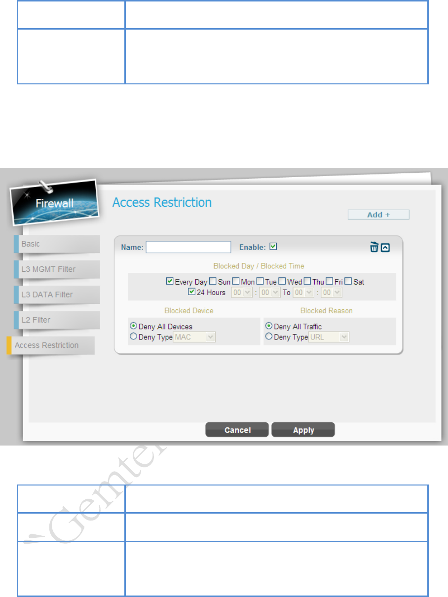
Firewall | Access Restriction
Firewall > Access Restriction
Add button
Click the “Add+” button to add a new rule setting.
Cancel button
Reset fields to the last saved values.
Apply button
Commit the changes made and save to the CPE device, some
services will be reloaded.
LTE Indoor CPE | User Manual P. 42
Management
The “Management” page allows you to configure the main system parameters; such as
password change, language, device time/name, factory default, etc.
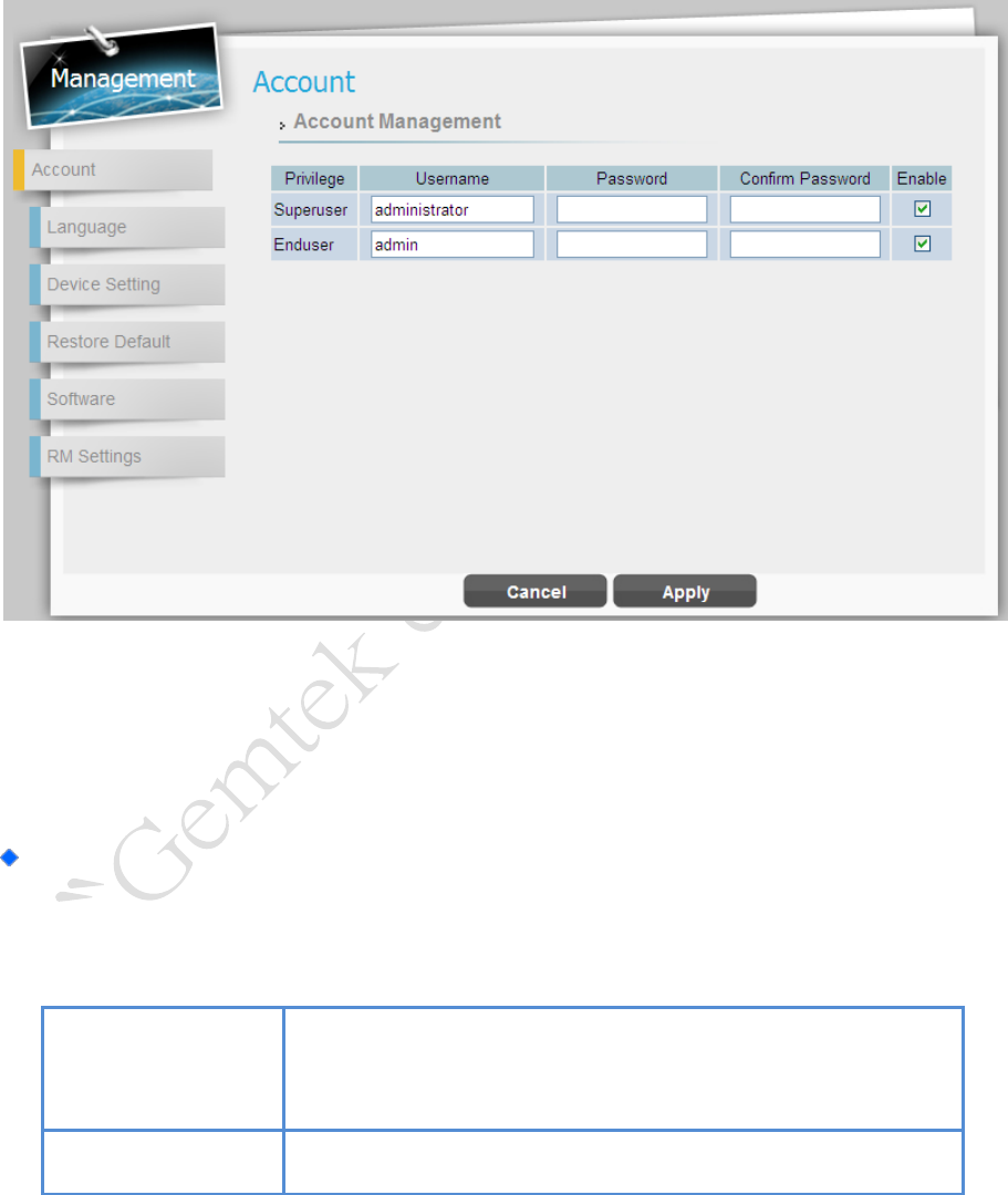
Management | Account
Management > Account
The Account Management page enables you to change the default username and password
for remote and local access to the Graphical User Interface (GUI).
Enter the new login information in the fields; there are at least 9 characters in
password setting. Click “Apply” to save this change to the CPE.
Apply button
Commit the changes have been made and save them to the
CPE device.
Cancel button
Reset fields to the last saved values.
LTE Indoor CPE | User Manual P. 43
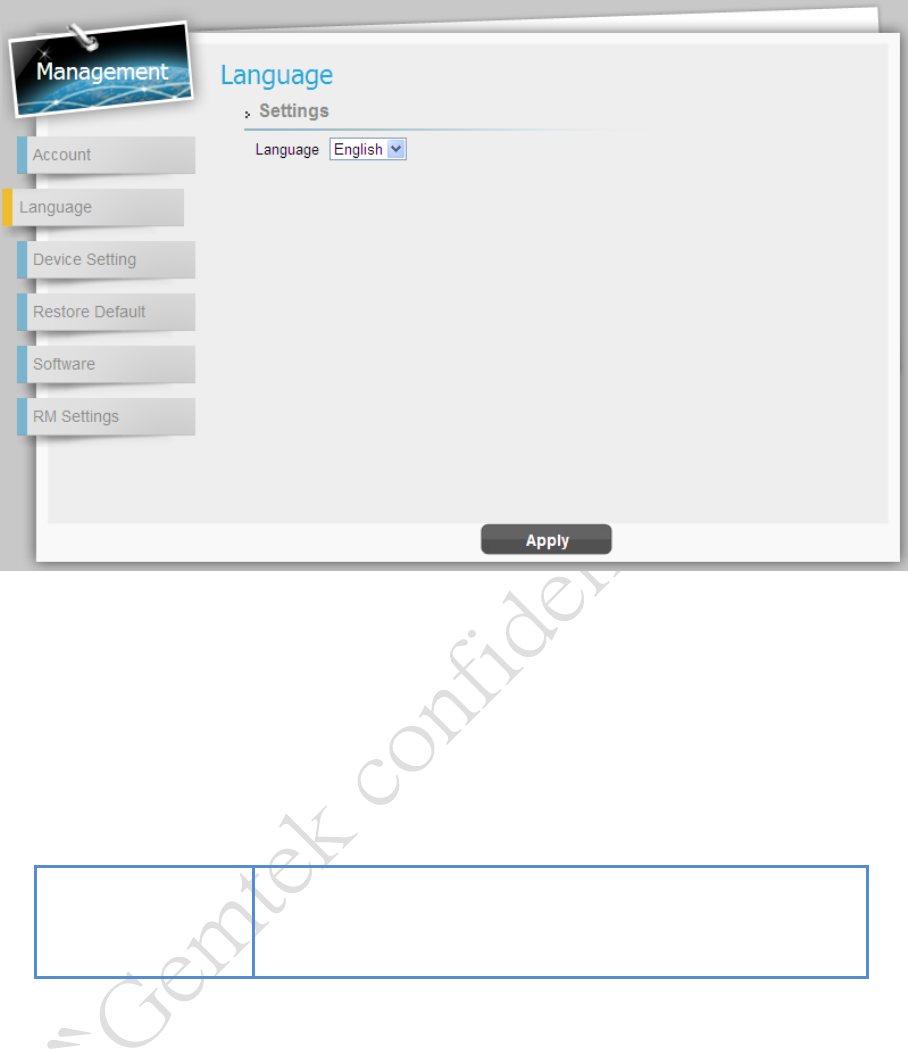
Management | Language
Management > Language
The language page allows you to switch the GUI languages as desired. Select the language
you want from the drop down list and then click “Apply” button to apply the changes to the
CPE.
Apply button
Commit the changes have been made and save them to the
CPE device.
LTE Indoor CPE | User Manual P. 44
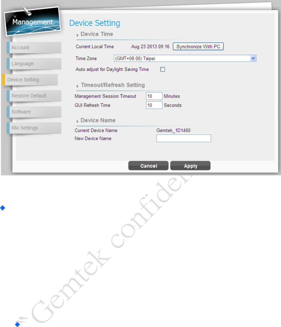
Management | Device Setting
Management > Device Setting
Device Time
Current Local Time: Display current local time; or click “Synchronize with PC”
button to synchronize the time in CPE with PC.
Time Zone: Select the proper time zone for your location on the drop down
menu.
Auto Adjust for Daylight Saving Time: Please enable this option if your
location observes Daylight Savings Time.
Timeout/Refresh Setting
Management Session Timeout: To prevent the number of sessions to
increase infinitely, CPE would automatically logout after a certain time of
period if idled. Enter the value in minute for a foundation to kill the session
after this period. (Range: 0-10 Minutes; 0 means never expired)
GUI Refresh Time: Enter the value in second for refreshing GUI in Status
page. (Range: 5-60 Seconds)
LTE Indoor CPE | User Manual P. 45
Device Name: Define a specific name for your device, so that you can login to this
device from any PC on your internal network by entering the device name on the
address bar. The default device name is “Airtel_EF819B”.
Current Device Name: Display the current device name.
New Device Name: Enter a new name for your device (Maximum 20 ASCII
Printable Characters allowed).
Cancel button
Reset fields to the last saved values.
Apply button
Commit the changes have been made and save them to the
CPE device.
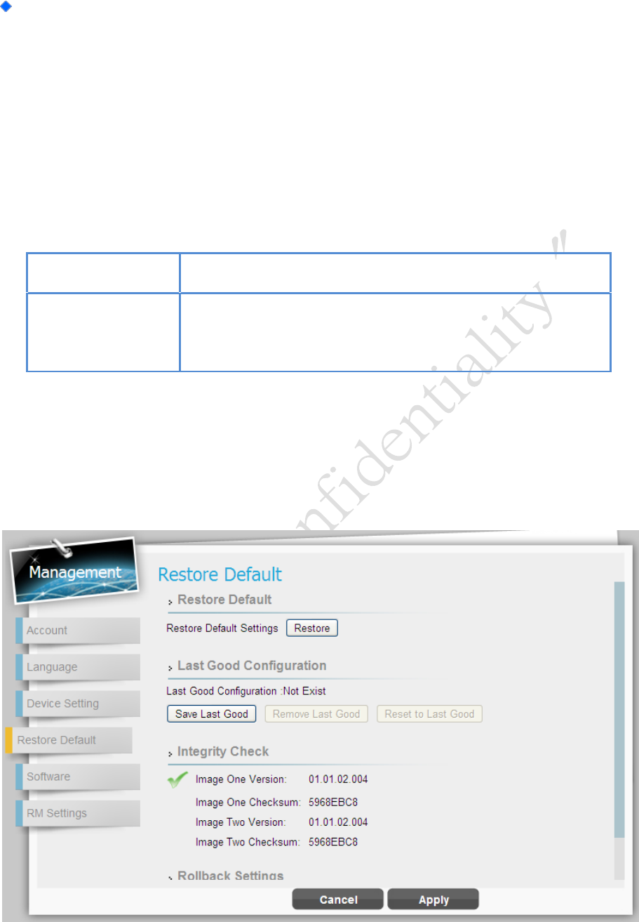
Management | Restore Default
Management > Restore Default
LTE Indoor CPE | User Manual P. 46
Cancel button
Reset fields to the last saved values.
Apply button
Commit the changes have been made and save them to the
CPE device.
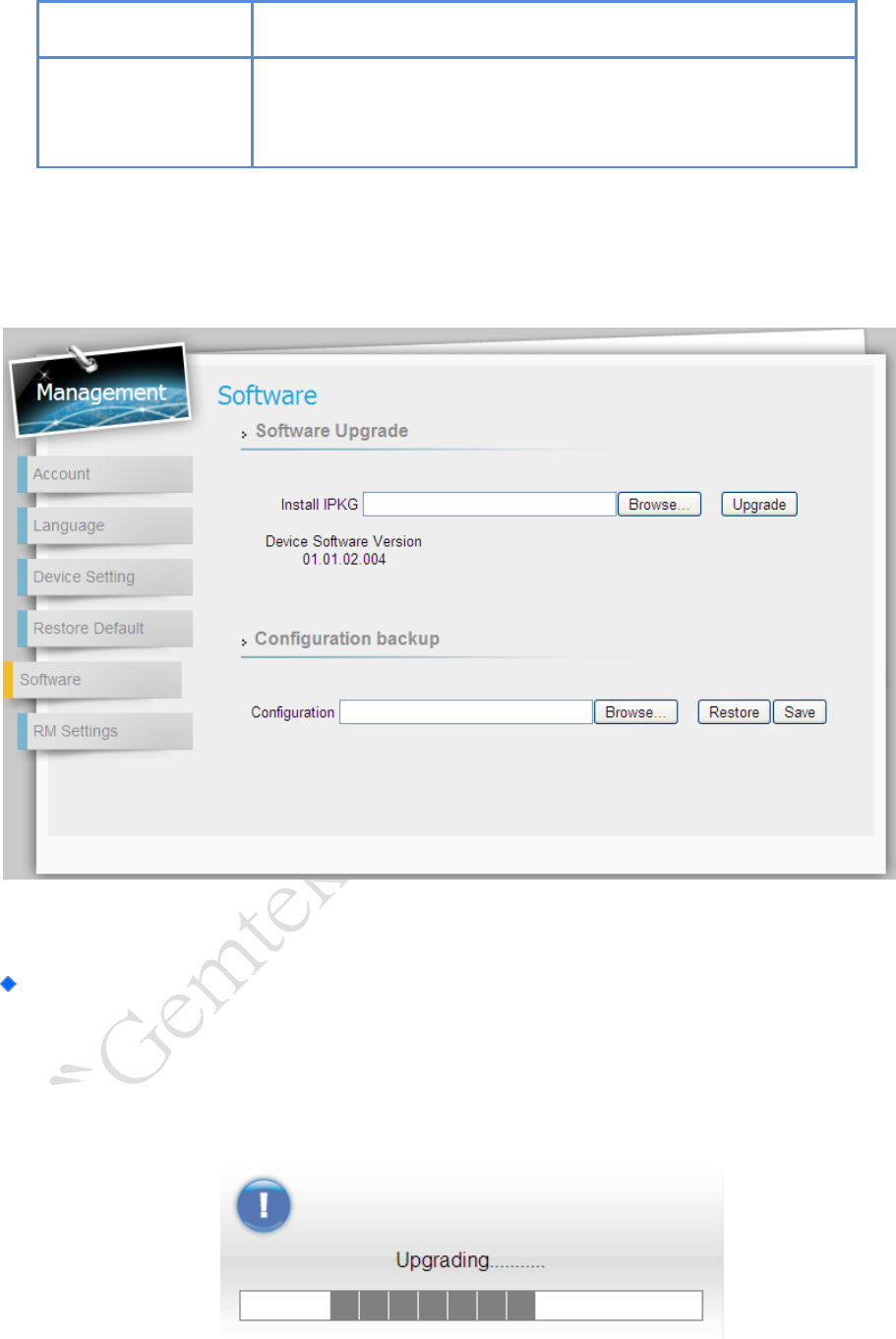
Management | Software
Management > Software
Software Upgrade: Click “Browse” button to select update file, and then click
“Upgrade” to install the selected file. The Upgrading window will be shown as below
and then reboot process will be started to apply the change.
Management > Software > Upgrading Window
LTE Indoor CPE | User Manual P. 47
After pressing the “Upgrade” button, it will automatically reboot the
CPE and upgrade the firmware with the specified file. You will be
prompted to login to the CPE after the upgrade is complete.
Configuration Backup: Backup current system configuration by clicking “Save”
button; and then select the destination and save the file for further backup
requirement.
File Download Window
If you want to restore the system to previous configuration, click “Browse” button to
select the previous-saved configuration file, and then click “Restore” button to
restore the system to previous settings.
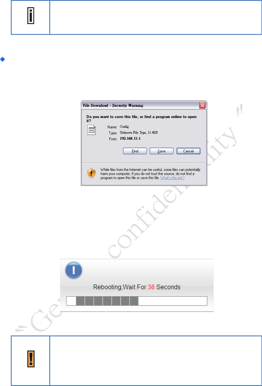
Management > Software > Upgrading Window
A Passphrase enter window will be popped up when save/restore the
configuration; be noted that the entered passphrases need to be
exactly the same to finish save/restore process.
LTE Indoor CPE | User Manual P. 48
Enter Passphrase Window
After pressing the “Restore” button, it will automatically reboot the
CPE and upgrade the configuration with the specified file. You will be
prompted to login to the CPE after the process is complete.
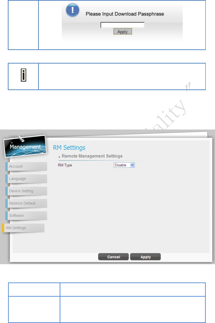
Management | RM Settings
Management > RM Settings
Cancel button
Reset fields to the last saved values.
Apply button
Commit the changes have been made and save them to the
CPE device.
LTE Indoor CPE | User Manual P. 49
Monitoring
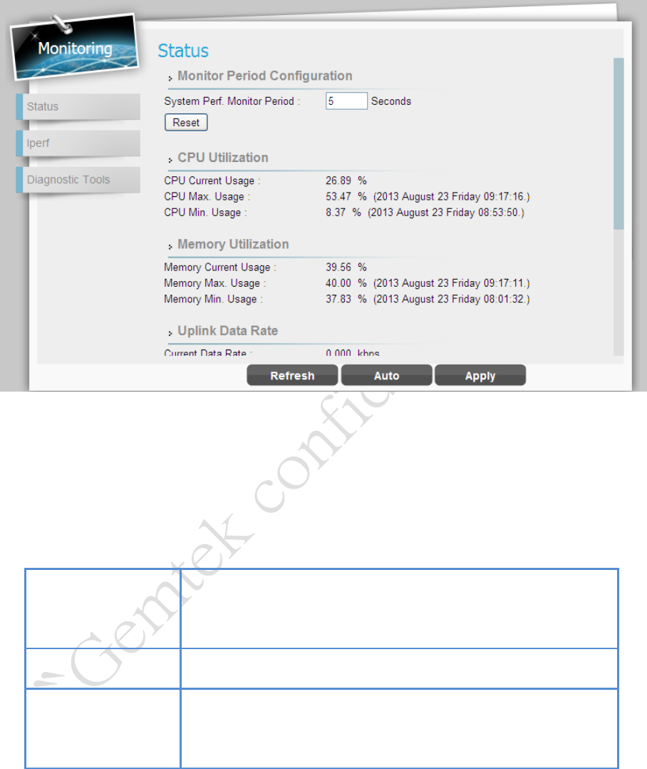
Monitoring | Status
Monitoring > Status
This page allows users to view the current status of device, CPU/memory usage, and
uplink/downlink data rate.
Refresh button
Click the “Refresh” button to receive the latest LTE
connection status.
Auto button
This button will update the status information periodically.
Apply button
Commit the changes have been made and save them to the
CPE device.
LTE Indoor CPE | User Manual P. 50
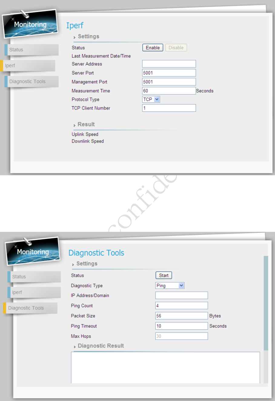
Monitoring | Iperf
Monitoring > Iperf
Monitoring | Diagnostic Tools
Monitoring > Diagnostic Tools
LTE Indoor CPE | User Manual P. 51
About
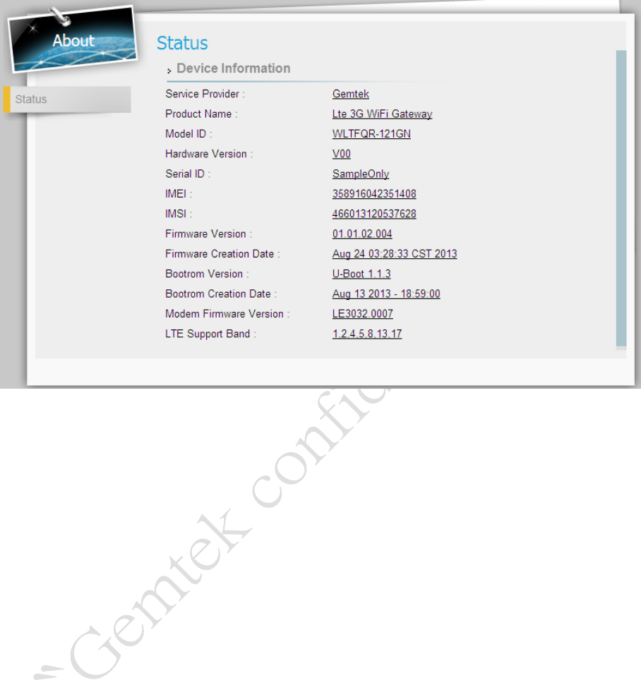
About | Status
About > Status
Select About > Status to display the basic information of CPE such as: Service Provider,
Product Name, Device Model ID, device Hardware Version, Serial ID, firmware version, and
bootrom program version.