GemTek Technology WMDD209A Lora module User Manual
Gemtek Technology Co., Ltd. Lora module Users Manual
Users Manual

WMDD-209A LoRa Module User
Manual
Version : 1.0.2

Release History
Release date
Release version
Main Delta
Arthur
2017/04/24
1.0.1
1. Initialize the document
Owen Hsu
2017/09/15
1.0.2
1. Hardware design
change
Owen Hsu
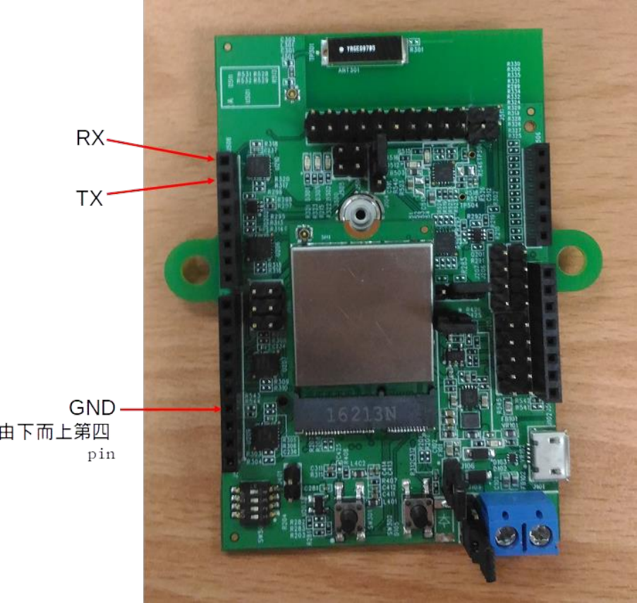
1. Hardware Figure
The following are the hardware picture and its pin definition.
(Figure 1)
Before using the module, you must have power supply, you can have a power supply by
connecting usb.
After power on, the user can access the module by AT command.
In WMDD-209A, the user have to use UART to send / receive data to / from the node
You can refer to the following pic and figure 2 to connect UART for using the console.

2. Configuration setting and related command
ABP mode:
In ABP mode, the user needs to configure 3 parameters, which are
device address, network session key, application session key.
The following AT commands are for end user to set the 3 parameters on
WMDD-209A.
AT+ECHO=1 /*show the characters user
input*/
AT+CMODE=1 /*set node to ABP mode*/
AT+CDEVADDR=<device address> /*set device address*/
AT+CNWKSKEY=<network session key> /*set network session key*/
AT+CAPPSKEY=<application session key> /*set application session
key*/
AT&W /*save the configuration*/
ATZ /*reboot the node*/
If the gateway is set well too, users can follow the instruction to send
packets.
AT+DTTX /*quick send, the message is device
address*/
AT+DTX=<msgLength>,<shot msg>
AT+DTX=2,"Hi"
AT+DTX=11,"Hello World"
If for testing the LoRa function, you can use the following configuration.
AT+CDEVADDR=0D000016
AT+CNWKSKEY=933C5ACB0D941ED1EC32DA7D9174C452
AT+CAPPSKEY=933C5ACB0D941ED1EC32DA7D9174C452

OTAA mode:
In OTAA mode, the user needs to prepare 3 parameters, which are
application EUI, device EUI and application key.
The following AT commands are for end user to set the 3 parameters
above on WMDD-209A.
AT+ECHO=1 /*show the characters user
input*/
AT+CMODE=0 /*set node to OTAA mode*/
AT+CDEVEUI=<device EUI> /*set device address*/
AT+CAPPEUI=<application EUI> /*set network session key*/
AT+CAPPKEY=<application key> /*set application session key*/
AT&W /*save the configuration*/
ATZ /*reboot the node*/
If the gateway is set well too, users can follow the instruction to send
packets.
AT+DTTX /*quick send, the message is device
address*/
or
AT+DTX=<msgLength>,<shot msg>
AT+DTX=2,"Hi"
AT+DTX=11,"Hello World"
Federal Communication Commission Interference Statement
This equipment has been tested and found to comply with the limits for a Class B digital
device, pursuant to Part 15 of the FCC Rules. These limits are designed to provide
reasonable protection against harmful interference in a residential installation. This
equipment generates, uses and can radiate radio frequency energy and, if not installed and
used in accordance with the instructions, may cause harmful interference to radio
communications. However, there is no guarantee that interference will not occur in a
particular installation. If this equipment does cause harmful interference to radio or television
reception, which can be determined by turning the equipment off and on, the user is
encouraged to try to correct the interference by one of the following measures:
- Reorient or relocate the receiving antenna.
- Increase the separation between the equipment and receiver.
- Connect the equipment into an outlet on a circuit different from that to which the receiver
is connected.
- Consult the dealer or an experienced radio/TV technician for help.
FCC Caution: Any changes or modifications not expressly approved by the party responsible
for compliance could void the user's authority to operate this equipment.
This device complies with Part 15 of the FCC Rules. Operation is subject to the following two
conditions: (1) This device may not cause harmful interference, and (2) this device must
accept any interference received, including interference that may cause undesired operation.
IMPORTANT NOTE:
Radiation Exposure Statement:
This equipment complies with FCC radiation exposure limits set forth for an
uncontrolled environment. This equipment should be installed and operated with
minimum distance 20cm between the radiator & your body.
This transmitter must not be co-located or operating in conjunction with any other antenna or
transmitter.
Country Code selection feature to be disabled for products marketed to the US/CANADA
Operation of this device is restricted to indoor use only

This device is intended only for OEM integrators under the following conditions:
1) The antenna must be installed such that 20 cm is maintained between the antenna
and users, and
2) The transmitter module may not be co-located with any other transmitter or antenna,
As long as 2 conditions above are met, further transmitter test will not be required. However,
the OEM integrator is still responsible for testing their end-product for any additional
compliance requirements required with this module installed
IMPORTANT NOTE
In the event that these conditions can not be met (for example certain laptop configurations
or co-location with another transmitter), then the FCC authorization is no longer considered
valid and the FCC ID can not be used on the final product. In these circumstances, the OEM
integrator will be responsible for re-evaluating the end product (including the transmitter) and
obtaining a separate FCC authorization.
End Product Labeling
This transmitter module is authorized only for use in device where the antenna may be
installed such that 20 cm may be maintained between the antenna and users. The final end
product must be labeled in a visible area with the following: “Contains FCC ID:”MXF-
WMDD209A”.
Manual Information to the End User
The OEM integrator has to be aware not to provide information to the end user regarding
how to install or remove this RF module in the user’s manual of the end product which
integrates this module.
The end user manual shall include all required regulatory information/warning as show in this
manual.