GemTek Technology WVVDB-101N 7130 Residential Gateway 6Vz.A2131 User Manual 6Ve AB2131
Gemtek Technology Co., Ltd. 7130 Residential Gateway 6Vz.A2131 6Ve AB2131
User Manual

CellPipe® 7130
VDSL RESIDENTIAL GATEWAY
6Vz.A2131,6Ve.B2131 | RELEASE 1.0
USER MANUAL
3EQ-10280-AAAA-TCZZA
EDITION 01
FEBRUARY 2011
Alcatel, Lucent, Alcatel-Lucent, the Alcatel-Lucent logo, and CellPipe are trademarks of Alcatel-Lucent. All other trademarks are the property of their
respective owners.
The information presented is subject to change without notice. Alcatel-Lucent assumes no responsibility for inaccuracies contained herein.
Alcatel-Lucent provides this documentation without warranty of any kind, implied or expressed, including, but not limited to, the implied warranties of
merchantability and fitness for a particular purpose.
Copyright © 2010 Alcatel-Lucent. All rights reserved.
Conformance statements
The equipment has been tested in the regulation lab and complied with the limits for VDSL device, pursuant to Europe CE/CB, Australia A-Trick and China
CCC. These limits of different regulations are designed provide reasonable protection against harmful interference or damage in a residential installation.
Security statement
In rare instances, unauthorized individuals make connections to the telecommunications network through the use of remote access features. In such an event,
applicable tariffs require the customer to pay all network charges for traffic. Alcatel-Lucent cannot be responsible for such charges and will not make any
allowance or give any credit for charges that result from unauthorized access.
IMPORTANT NOTICE: This document contains confidential information that is proprietary to Alcatel-Lucent. No part of its contents may be used, copied,
disclosed or conveyed to any party in any manner whatsoever without prior written permission from Alcatel-Lucent.
www.alcatel-lucent.com

iii
3EQ-10280-AAAA-TCZZA
Edition 01 February 2011
............................................................................................................................................................................................................................................................
About this document
Purpose
This document provides information on the hardware setup, software configuration, and
administration necessary to operate the CellPipe 7130 Residential Gateway 6Vz.A2131/
6Ve.B2131.
Reason for revision
The following table shows the revision history of this document.
Intended audience
This document is intended for users and administrators of the CellPipe 7130 RG
6Vz.A2131/6Ve.B2131.
How to use this document
This document introduces the CellPipe 7130 RG 6Vz.A2131/6Ve.B2131 hardware,
connections, and setup. It also explains the web configuration interface and provides
parameter definitions for the fields that appear on those windows.
Conventions used
This guide uses the following typographical conventions:
Revision Date Reason for reissue
Edition 01 February 2011 First release of this document
Appearance Description
Italicized text •File and directory names.
•Emphasized information.
•Titles of publications.
•A value that the user supplies.
graphical user interface text or
key name
•Text that is displayed in a graphical user
interface or in a hardware label.
•The name of a key on the keyboard.
............................................................................................................................................................................................................................................................
About this document
iv 3EQ-10280-AAAA-TCZZA
Edition 01 February 2011
............................................................................................................................................................................................................................................................
Structure of hazard statements
Overview
For the safety of you and your equipment, this document contains hazard statements.
Hazard statements are given at points where there may be a risk of damage to personnel,
equipment, or operation. Failure to follow the directions in a hazard statement may result
in personal harm, equipment damage, or network loss.
General structure
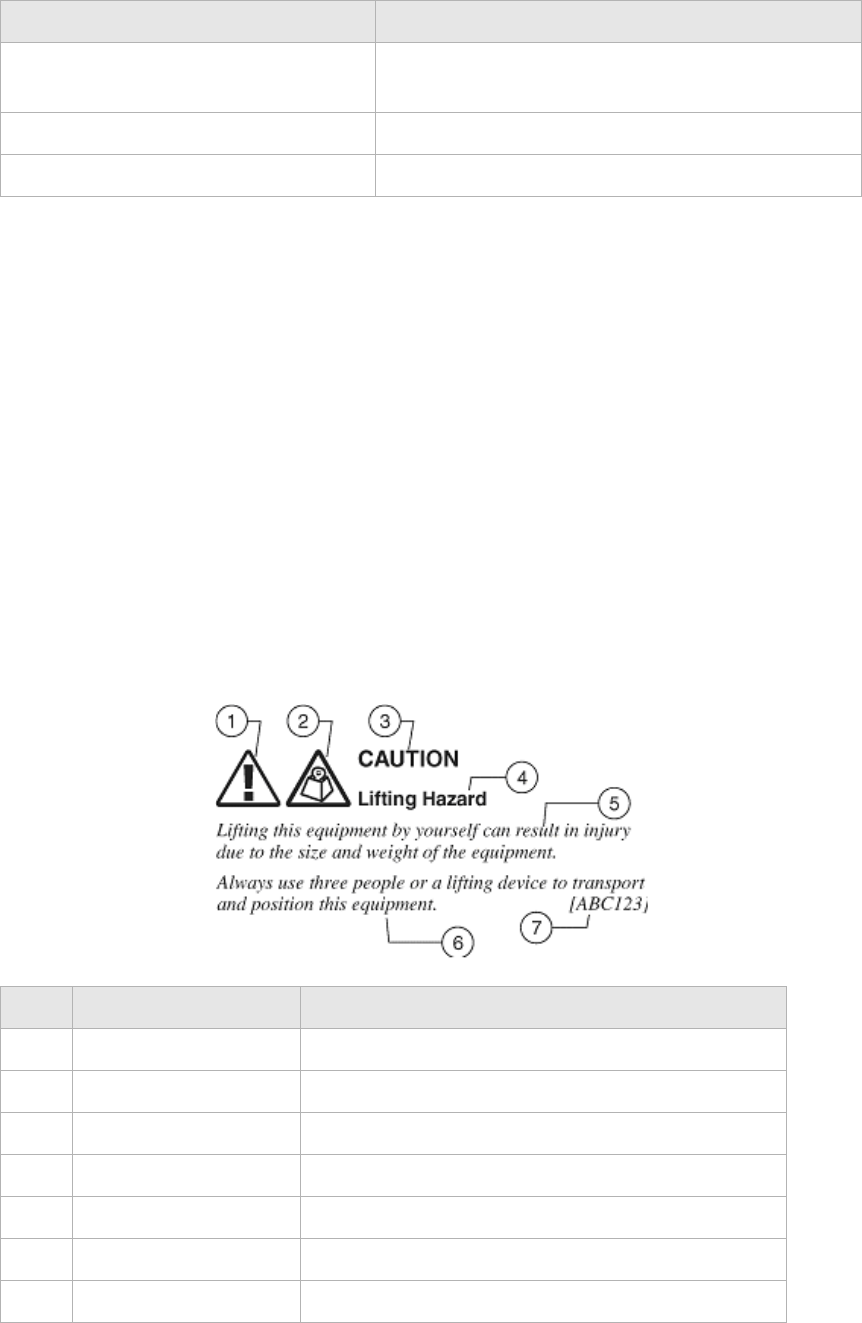
Hazard statements include the structural elements shown in the figure below.
Structure of hazard statements
input text Command names and text that the user types or
selects as input to a system.
output text Text that a system displays or prints.
Press the Return or Enter key on the keyboard.
Appearance Description
Item Structure element Purpose
1 Personal injury symbol Indicates the potential for personal injury (optional).
2 Hazard type symbol Indicates hazard type (optional).
3 Signal word Indicates the severity of the hazard.
4 Hazard type Describes the source of the risk of damage or injury.
5 Damage statement Consequences if protective measures fail.
6 Avoidance message Protective measures to take to avoid the hazard.
7 Identifier The reference ID of the hazard statement (optional).

About this document
............................................................................................................................................................................................................................................................
3EQ-10280-AAAA-TCZZA
Edition 01 February 2011 v
............................................................................................................................................................................................................................................................
Signal words
The following table defines signal words that identify the hazard severity levels.
Signal words for hazard severity
Related information
The documentation set accompanying this family of routers includes this User Manual
and a Quick Installation Guide.
Technical support
For technical support, contact your local Alcatel-Lucent customer support team. See the
Alcatel-Lucent Support website (http://alcatel-lucent.com/support/) for contact
information.
Signal word Meaning
DANGER Indicates an imminently hazardous situation (high
risk) which, if not avoided, will result in death or
serious injury.
WARNING Indicates a potentially hazardous situation (medium
risk) which, if not avoided, could result in death or
serious injury.
CAUTION When used with the personal injury symbol:
Indicates a potentially hazardous situation (low risk)
which, if not avoided, may result in personal injury.
When used without the personal injury symbol:
Indicates a potentially hazardous situation (low risk)
which, if not avoided, may result in property
damage, such as service interruption or damage to
equipment or other materials.
............................................................................................................................................................................................................................................................
About this document
vi 3EQ-10280-AAAA-TCZZA
Edition 01 February 2011
............................................................................................................................................................................................................................................................

vii
3EQ-10280-AAAA-TCZZA
Edition 01 February 2011
............................................................................................................................................................................................................................................................
Contents
1Product overview
Hardware introduction ............................................................................................................................... 1-1
Safety precautions ..................................................................................................................................... 1-2
Prerequisites .............................................................................................................................................. 1-3
Description of LEDs and interfaces .......................................................................................................... 1-3
2 Hardware installation
To mount the CellPipe 7130 RG ............................................................................................................... 2-1
To install the CellPipe 7130 RG ................................................................................................................ 2-2
RGAM installation of the Residential Gateway Application Module .......................................................2-4
3 Accessing the CellPipe 7130 RG web configuration tool
To access the CellPipe 7130 RG web configuration tool ..........................................................................3-1
4 Status
System Usage ............................................................................................................................................ 4-1
WAN PTM Status ...................................................................................................................................... 4-3
DSL Link Status ........................................................................................................................................ 4-4
Device Table .............................................................................................................................................. 4-6
DHCP Lease .............................................................................................................................................. 4-7
WiFi Association .......................................................................................................................................4-8
WAN/(W)LAN Statistics ........................................................................................................................... 4-8
IGMP Membership .................................................................................................................................. 4-10
IGMP Statistics ........................................................................................................................................ 4-10
................................................................................................................................................................. 4-11
5Network
USB ........................................................................................................................................................... 5-1
LAN Settings ............................................................................................................................................. 5-3
WAN Link Selection ................................................................................................................................. 5-6
WAN PTM Connections ............................................................................................................................ 5-6
................................................................................................................................................................. 5-31
6WiFi setup
WiFi Settings ............................................................................................................................................. 6-1
WiFi Security ............................................................................................................................................. 6-4
............................................................................................................................................................................................................................................................
Contents
viii 3EQ-10280-AAAA-TCZZA
Edition 01 February 2011
............................................................................................................................................................................................................................................................
WiFi Access Filter ..................................................................................................................................... 6-6
7 Firewall setup
Port Forwarding ........................................................................................................................................ 7-1
Demilitarized Zone .................................................................................................................................... 7-3
UPnP ......................................................................................................................................................... 7-4
Layer 2 Filter ............................................................................................................................................. 7-5
Layer 3 Filter ............................................................................................................................................. 7-7
NAT Passthrough ...................................................................................................................................... 7-8
URL Blocking ........................................................................................................................................... 7-9
Content Screening ................................................................................................................................... 7-10
Parental Control ...................................................................................................................................... 7-11
8Advanced setup
Route Settings ........................................................................................................................................... 8-1
DNS Settings ............................................................................................................................................. 8-3
Dynamic DNS ........................................................................................................................................... 8-4
System Log ................................................................................................................................................ 8-5
IGMP Proxy/Snooping .............................................................................................................................. 8-6
802.1x Config ............................................................................................................................................ 8-7
9QoS PTM setup
QoS Overview ........................................................................................................................................... 9-1
QoS Scheduler ........................................................................................................................................... 9-2
................................................................................................................................................................... 9-4
QoS Policy ................................................................................................................................................ 9-5
QoS Phone ................................................................................................................................................. 9-7
QoS ALG .................................................................................................................................................. 9-8
QoS Defaults ........................................................................................................................................... 9-10
QoS MAC ................................................................................................................................................ 9-12
10 Telephony
Account Setup ......................................................................................................................................... 10-1
Service Settings ....................................................................................................................................... 10-4
SIP Server Settings .................................................................................................................................. 10-8
RTP/Codecs settings .............................................................................................................................. 10-10
Account & Line Table ........................................................................................................................... 10-12
Call History ........................................................................................................................................... 10-13
Other Settings ........................................................................................................................................ 10-14

Contents
ix
3EQ-10280-AAAA-TCZZA
Edition 01 February 2011
............................................................................................................................................................................................................................................................
............................................................................................................................................................................................................................................................
11 Utilities
Configuration Backup ..............................................................................................................................11-1
Configuration Restore ..............................................................................................................................11-2
Firmware Upgrade ...................................................................................................................................11-3
System Settings ........................................................................................................................................11-4
Management Access Control ................................................................................................................... 11-7
CWMP Management ...............................................................................................................................11-8
Connection Test .....................................................................................................................................11-10
802.1x CA Upload ................................................................................................................................. 11-11
Restore Factory Defaults ....................................................................................................................... 11-11
Reboot Gateway .....................................................................................................................................11-12
RGAM Management .............................................................................................................................11-13
A Troubleshooting
B TCP/IP configuration
C Product conformance
EU declaration of conformity ................................................................................................................... C-1
FCC 15B statement ................................................................................................................................... C-3
FCC Part 68 Statement ............................................................................................................................. C-4
Industry Canada statement ........................................................................................................................ C-5
IC TELECOM .......................................................................................................................................... C-5
GL Glossary
............................................................................................................................................................................................................................................................
Contents
x 3EQ-10280-AAAA-TCZZA
Edition 01 February 2011
............................................................................................................................................................................................................................................................

1-1
3EQ-1028-AAAA-TCZZA
Edition 01 February 2011
............................................................................................................................................................................................................................................................
1Product overview
Overview
Purpose
This chapter provides an introduction to the physical aspects of the CellPipe 7130 RG
6Vz.A2131/6Ve.B2131 including safety precautions and features.
The CellPipe 7130 RG 6Vz.A2131/6Ve.B2131 will be referred to as
CellPipe 7130 RG throughout the rest of this document.
Contents
This chapter covers the following topics:
Hardware introduction
The CellPipe 7130 RG connects residential users to a broadband WAN via an Ethernet-
over-VDSL link or a Gigabit Ethernet connection. For this purpose, it provides the
following WAN interfaces:
•one VDSL port
•one Gigabit Ethernet port
Note: The WAN interfaces cannot be used concurrently.
The devices on the LAN of residential users are interconnected and connected to the
WAN via IP routing or Ethernet bridging. The following interfaces can be used to connect
devices in the home:
•Four Gigabit Ethernet LAN ports (10/100/1000Base-TX)
Hardware introduction 1-1
Safety precautions 1-2
Prerequisites 1-3
Description of LEDs and interfaces 1-3
............................................................................................................................................................................................................................................................
Safety precautionsProduct overview
1-2 3EQ-1028-AAAA-TCZZA
Edition 01 February 2011
............................................................................................................................................................................................................................................................
•wireless access point
Safety precautions
WARNING
Risk of electric shock or fire
1. Pay attention to the power load of the electrical outlet or extension cord. An
overburdened power outlet or damaged cords and plugs may cause electric shock or
fire. Check the power cords regularly. If you find any damage, replace the cord
immediately.
2. Leave adequate space for heat dissipation to avoid any damage caused by overheating
the CellPipe 7130 RG. Do not cover the ventilation holes. Blocking the ventilation
holes may cause fire.
3. When connecting a PC or other electronic device to the CellPipe 7130 RG, make sure
you use the right cables and connect the device to the right port of the CellPipe 7130
RG. Incorrect connections may damage the device and/or CellPipe 7130 RG..
CAUTION
Potential equipment damage
Follow these recommendations to protect yourself and the CellPipe 7130 RG from harm:
1. Do not insert any sharp object into the openings of the CellPipe 7130 RG..
2. Never install telephone wiring during inclement weather; for example, during a storm.
3. Electrostatic discharge (ESD) can permanently damage semiconductor devices.
Always follow ESD-prevention guidelines for equipment handling and storage.
4. Use the power adapter provided with the CellPipe 7130 RG and do not fasten the
power cable to building surfaces. Ensure the cable can move freely. Do not place
heavy objects on the cable. Check the power cords regularly. If you find any damage,
replace the cord immediately.
5. Do not put the CellPipe 7130 RG near a heat source. Avoid placing the CellPipe 7130
RG in direct sunlight.
6. Do not put the CellPipe 7130 RG in damp or wet locations. Do not spill any liquid on
the CellPipe 7130 RG..
7. Do not place the CellPipe 7130 RG on an unstable surface or support.
8. Do not place heavy objects on top of the CellPipe 7130 RG..
9. Do not use liquid or aerosol cleaners; use a soft, dry cloth for cleaning.
Product overviewPrerequisites
............................................................................................................................................................................................................................................................
3EQ-1028-AAAA-TCZZA
Edition 01 February 2011 1-3
............................................................................................................................................................................................................................................................
Prerequisites
Ensure that you have the following items before attempting to use the CellPipe 7130 RG:
•Internet services subscription (connection type, account information, and addresses)
•10/100Base-T Ethernet NIC installed in your PC
•Operating system: Windows 98SE, Windows 2000, Windows NT, Windows ME,
Windows XP, Windows Vista, Windows 7, or Mac OS
•Internet Explorer v4.0 or higher, Netscape v4.0 or higher, or Mozilla Firefox v1.5 or
higher
Note: For optimal display quality, use Internet Explorer v5.0 or Netscape v6.1.
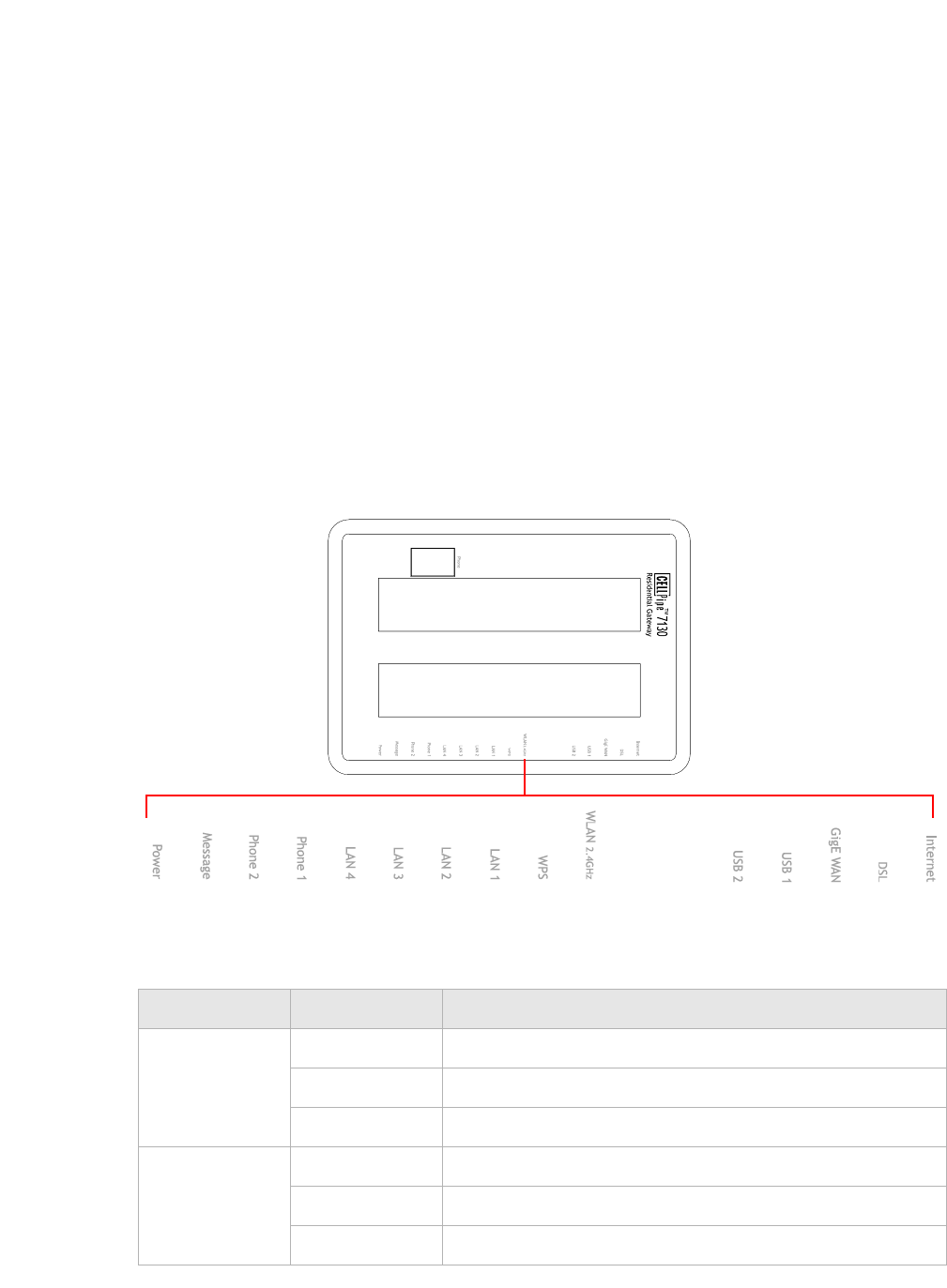
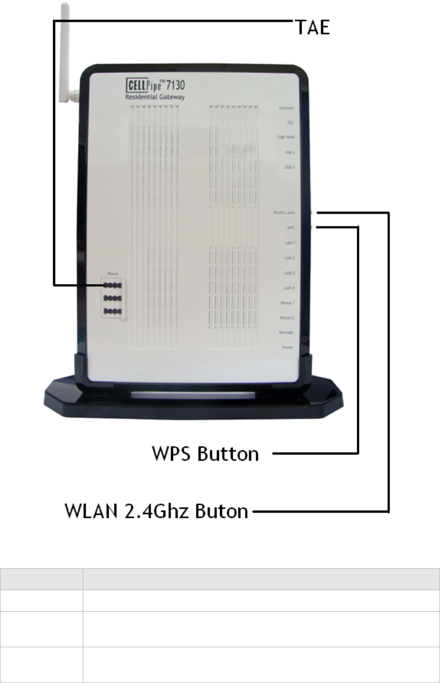
Description of LEDs and interfaces
Figure 1-1 Front panel
Table 1-1 Front panel LEDs
LED Status Description
Internet On The CellPipe 7130 RG is connected to the Internet.
Flashing Data is being transmitted over the Internet connection.
Off The CellPipe 7130 RG is not connected to the Internet.
DSL On DSL is operating.
Flashing DSL is training.
Off DSL is disconnected.

............................................................................................................................................................................................................................................................
Description of LEDs and interfacesProduct overview
1-4 3EQ-1028-AAAA-TCZZA
Edition 01 February 2011
............................................................................................................................................................................................................................................................
GigE WAN On Gigabit Ethernet WAN link is up.
Flashing Data is being transmitted on the Gigabit Ethernet WAN
link.
Off Gigabit Ethernet WAN is disconnected.
USB 1 to 2 On A device is connected to the USB port.
Flashing USB port has data traffic.
Off No device is connected to USB port.
WLAN2.4GHz On Wireless function is enabled.
Flashing Data is being transmitted on the wireless link.
Off Wireless function is disabled.
WPS On WPS is enabled.
Off WPS is disabled.
LAN 1 to 4 On Ethernet LAN port 1 to 4 is connected and active.
Flashing Network activity over the corresponding ports.
Off Ethernet LAN port 1 to 4 is not active.
Phone 1 to 2 On Phone 1 to 2 is connected.
Off No phones are connected.
Message Slow flashing*Firmware upgrade in progress.
Off No firmware upgrade in progress.
Power On CellPipe 7130 RG is powered on.
Off Power is disconnected.
Notes:
* Slow flashing: LED flashes at the rate of 2 seconds on and 2 seconds off.
LED Status Description
Product overviewDescription of LEDs and interfaces
............................................................................................................................................................................................................................................................
3EQ-1028-AAAA-TCZZA
Edition 01 February 2011 1-5
............................................................................................................................................................................................................................................................
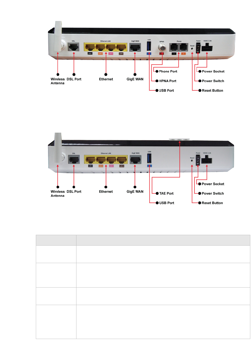
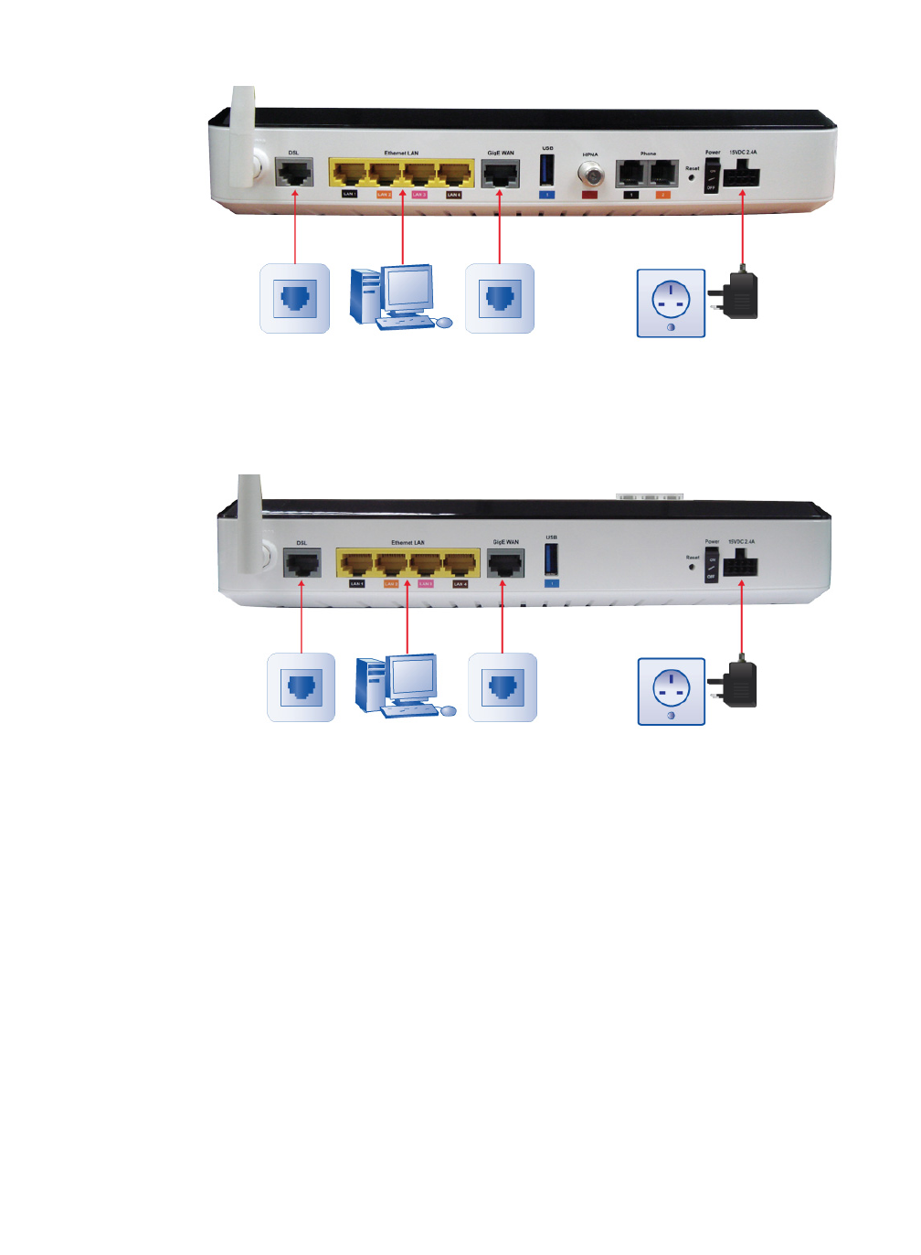
Figure 1-2 Rear panel of 6Vz.A2131
Figure 1-3 Rear panel of 6Ve.B2131
Table 1-2 Rear panel items
Item Description
Wireless
Antennae
Antennae for transmission of wireless signal.
DSL Port DSL network connection from your ISP. The DSL port connects to an RJ-11
cable (only for 6Vz.A2131). The DSL port connects to an TAE-RJ45 cable
(only for 6Ve.B2131).
Ethernet LAN1
to LAN4
Four RJ-45 ports to connect up to four PCs or a Hub.
GigE WAN Ethernet network connection from your ISP. The GigE WAN port connects
to an RJ-45 cable.
Note: The GigE Ethernet port cannot be used simultaneously with the DSL
port.

............................................................................................................................................................................................................................................................
Description of LEDs and interfacesProduct overview
1-6 3EQ-1028-AAAA-TCZZA
Edition 01 February 2011
............................................................................................................................................................................................................................................................
USB Support USB 2.0 for file sharing, printer sharing, UPnP digital Media
sharing and sensor network interface support.
HPNA (only
for
6Vz.A2131)
One HPNA interface to connect to a HPNA device.
Phone 1 to 2
(only for
6Vz.A2131)
Two RJ-11 ports for connecting telephones for VoIP.
Reset Button Press and release to reboot the CellPipe 7130 RG. Press and hold for 10
seconds to restore to factory default settings.
Power Switch Power On/Off switch.
15VDC 2.4A DC power adapter port.
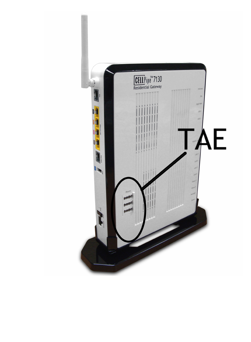
TAE (only for
6Ve.B2131)
Slot to insert the CellPipe 7130 Residential Gateway Application Module .
See Figure 1-4
Item Description
Product overviewDescription of LEDs and interfaces
............................................................................................................................................................................................................................................................
3EQ-1028-AAAA-TCZZA
Edition 01 February 2011 1-7
............................................................................................................................................................................................................................................................
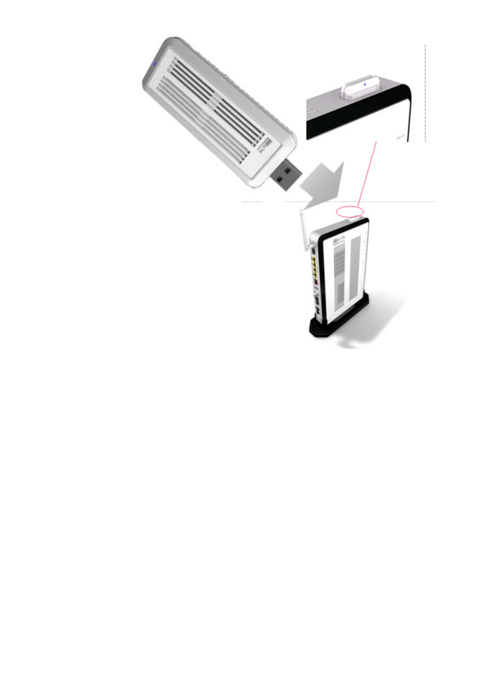
Figure 1-4 TAE interface for the CellPipe 7130 6Ve.B2131 residential gateway
............................................................................................................................................................................................................................................................
Description of LEDs and interfacesProduct overview
1-8 3EQ-1028-AAAA-TCZZA
Edition 01 February 2011
............................................................................................................................................................................................................................................................
Figure 1-5 Front side of 6Ve.B2131
Table 1-3 Front side items
Item Description
WPS Activates the Wireless Protected Setup (WPS) function
WLAN
2.4GHz
Button to activate and de-activation the Wireless interface.
TAE (only for
6Ve.B2131)
TAE phone connector

Product overviewDescription of LEDs and interfaces
............................................................................................................................................................................................................................................................
3EQ-1028-AAAA-TCZZA
Edition 01 February 2011 1-9
............................................................................................................................................................................................................................................................
............................................................................................................................................................................................................................................................
Description of LEDs and interfacesProduct overview
1-10 3EQ-1028-AAAA-TCZZA
Edition 01 February 2011
............................................................................................................................................................................................................................................................

2-1
3EQ-10280-AAAA-TCZZA
Edition 01 February 2011
............................................................................................................................................................................................................................................................
2 Hardware installation
Overview
Purpose
This chapter provides the instructions to install the CellPipe 7130 RG hardware.
Contents
This chapter covers the following topics:
To mount the CellPipe 7130 RG
There are three ways to mount the CellPipe 7130 RG:
•wall mounting
•desktop mounting
•stand-up mounting
Wall mounting
Pre-Requirements
•Anchors
•Screws
•Drill & Drill bit
1. Locate a high position on the wall that is free of obstructions and insert two screws in
the wall 5 cm (2 in.) apart. Do not insert the screws all the way into the wall.
To mount the CellPipe 7130 RG 2-1
To install the CellPipe 7130 RG 2-2
RGAM installation of the Residential Gateway Application Module 2-4

............................................................................................................................................................................................................................................................
To install the CellPipe 7130 RGHardware installation
2-2 3EQ-10280-AAAA-TCZZA
Edition 01 February 2011
............................................................................................................................................................................................................................................................
Important! Make sure that the screws are securely fixed to the wall and strong
enough to hold the weight of the CellPipe 7130 RG (recommended screw type and
size: Nylon wall plug [T8x25mm] and screws [T3.5x16mm]).
2. Align the holes on the back of the CellPipe 7130 RG with the screws on the wall and
then hang the CellPipe 7130 RG on the screws.
........................................................................................................................................................
END OF STEPS
Desktop mounting
Place the CellPipe 7130 RG with the rubber feet at the bottom on a flat and stable surface.
Stand-up mounting
Snap the cradle into the holes located on the side of the CellPipe 7130 RG and then place
it on a desk so that LEDs are visible.
To install the CellPipe 7130 RG
Supplies
•CellPipe 7130 RG
•One RJ-11 telephone cable (only for 6Vz.A2131)
•One TAE-F to RJ45 cable (only for 6Ve.B2131)
•One RJ-45 category 5 Ethernet cable (yellow)
•Power adapter
Before you begin
CAUTION
Potential for equipment damage and personal harm
Before installing the CellPipe 7130 RG, ensure you have thoroughly read the Safety
precautions and Prerequisites in chapter 1.
Turn off all devices (computer, hub, CellPipe 7130 RG) before beginning this procedure.
Hardware installationTo install the CellPipe 7130 RG
............................................................................................................................................................................................................................................................
3EQ-10280-AAAA-TCZZA
Edition 01 February 2011 2-3
............................................................................................................................................................................................................................................................
Figure 2-1 Cable connections of 6Vz.A2131
Figure 2-2 Cable connections of 6Ve.B2131
Procedure
1. Connect one end of the gray RJ-11 cable (omly for 6Vz.A2131) or gray TAE-RJ45
cable (only for 6Ve.B2131) into the gray DSL port on the CellPipe 7130 RG and the
other end to your telephone/VDSL service connection.
2. Connect one end of the yellow RJ-45 Ethernet cable to any of the yellow Ethernet
LAN ports (1 to 4) on the CellPipe 7130 RG. Connect the other end of the cable to
your Ethernet PC (or LAN hub if you are setting up an intranet).
3. Turn the power switch on.
........................................................................................................................................................
END OF STEPS
You might need to configure the Internet properties on your Ethernet PC; see Appendix B,
TCP/IP configuration, or the Quick Installation Guide for detailed instructions.
After setting up the CellPipe 7130 RG and your PC(s), you can access the web
configuration tool; see Accessing the CellPipe 7130 RG web configuration tool.
............................................................................................................................................................................................................................................................
RGAM installation of the Residential Gateway Application
Module
Hardware installation
2-4 3EQ-10280-AAAA-TCZZA
Edition 01 February 2011
............................................................................................................................................................................................................................................................
RGAM installation of the Residential Gateway Application
Module
Purpose
The CellPipe 7130 Residential Gateway Application Module (RGAM) is an USB devices
which adds processing power to the residential gateway. This will allow future home
services to be deployed in your home, provided by your service provider.
Installation
As shown in the drawing, the RGAM has a USB 2.0 metal interface. This metal interface
should go into the RGAM slot first. The ventilation holes should facing up. Slide the
RGAM into the slot until it is blocked. Once inserted, the top of the RGAM will stick
outside the enclosure as illustrated below. Once the RGAM is inserted, the RGAM will
start up automatically. On the front panel of the residential gateway, the "USB 2" LED
will light up, indicating that the RGAM is up and running.
Hardware installationRGAM installation of the Residential Gateway Application
Module
............................................................................................................................................................................................................................................................
3EQ-10280-AAAA-TCZZA
Edition 01 February 2011 2-5
............................................................................................................................................................................................................................................................
Figure 2-3 RGAM installation
WARNING
Do not connect the RGAM to devices which are not RGAM-READY. This may damage
the RGAM or the device.
............................................................................................................................................................................................................................................................
RGAM installation of the Residential Gateway Application
Module
Hardware installation
2-6 3EQ-10280-AAAA-TCZZA
Edition 01 February 2011
............................................................................................................................................................................................................................................................

3-1
3EQ-10280-AAAA-TCZZA
Edition 01 February 2011
............................................................................................................................................................................................................................................................
3 Accessing the CellPipe
7130 RG web
configuration tool
Overview
Purpose
This chapter explains how to access the CellPipe 7130 RG web configuration tool by
entering the IP address and the default passwords.
The management interface software is HTML-based and can be accessed using a web
browser.
Contents
This chapter covers the following topic:
To access the CellPipe 7130 RG web configuration tool
When to use
Use this procedure to access the web configuration interface of the CellPipe 7130 RG. The
configuration interface enables you to secure the CellPipe 7130 RG, limit access, set
traffic routes, modify passwords, and configure advanced settings.
Before you begin
Before you can configure the CellPipe 7130 RG, it must be installed, connected to a web-
enabled PC, and turned on.
To establish the initial connection with the CellPipe 7130 Gateway, your computers
should be configured to obtain automatically a network address via DHCP or via statically
configuration of the network address. In this case, the IP address should be in the range of
192.168.2.2 up to 192.168.2.99, for instance 192.168.2.10 The netmask should be
255.255.255.0
To access the CellPipe 7130 RG web configuration tool 3-1
............................................................................................................................................................................................................................................................
To access the CellPipe 7130 RG web configuration toolAccessing the CellPipe 7130 RG web configuration tool
3-2 3EQ-10280-AAAA-TCZZA
Edition 01 February 2011
............................................................................................................................................................................................................................................................
Note: If you are not sure how to configure your computer to be a DHCP client or to
set your IP address and subnet mask, please refer to Appendix B, TCP/IP
configuration, or the Quick Installation Guide for more information.
Procedure
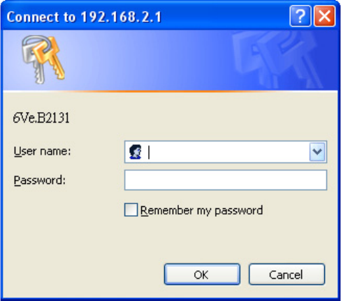
1. Open a web browser and enter the IP address of the CellPipe 7130 RG in the address
bar:
http://192.168.2.1
The login window appears; see Figure 3-1.
Figure 3-1 Login window
2. Enter your username and password and click OK.
The default admin username is admin and the default admin password is admin.
The Status window appears; see Figure 3-2.
Accessing the CellPipe 7130 RG web configuration toolTo access the CellPipe 7130 RG web configuration tool
............................................................................................................................................................................................................................................................
3EQ-10280-AAAA-TCZZA
Edition 01 February 2011 3-3
............................................................................................................................................................................................................................................................
Figure 3-2 Status window
The status window is described in Chapter 4, Status.
Note: Once you have logged in for the first time, you should change your login
password. See the System Settings section in the Utilities chapter for instructions.
3. Click the Logout button to log off; see Figure 3-3.
Figure 3-3 Logout button
........................................................................................................................................................
END OF STEPS
Configuration menus
All configuration and management of the CellPipe 7130 RG is done using the web
configuration tool. Click on Status, Network, WiFi Setup, Firewall Setup, Advanced
Setup, QoS PTM Setup, QoS ATM Setup, Teleph o n y, or Utilities in the main menu to
view the configuration menus or information located in each directory.
............................................................................................................................................................................................................................................................
To access the CellPipe 7130 RG web configuration toolAccessing the CellPipe 7130 RG web configuration tool
3-4 3EQ-10280-AAAA-TCZZA
Edition 01 February 2011
............................................................................................................................................................................................................................................................

4-1
3EQ-10280-AAAA-TCZZA
Edition 01 February 2011
............................................................................................................................................................................................................................................................
4 Status
Overview
Purpose
This chapter describes the contents of the Status menu, which contains the status
information for the CellPipe 7130 RG, its connections, and the connected hardware.
Click Status in the main menu to open the Status menu.
Contents
This chapter covers the following topics:
System Usage
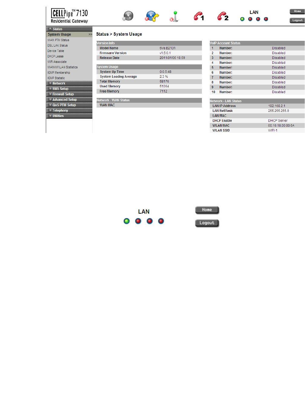
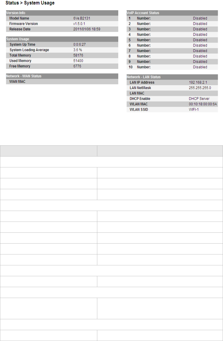
The System Usage window shows the current status of the software, system time,
memory, WAN connection, and LAN connection.
Select System Usage in the Status menu to access the System Usage window; see
Figure 4-1.
System Usage 4-1
WAN PTM Status 4-3
DSL Link Status 4-4
Table 4-3 Field descriptions 4-5
DHCP Lease 4-7
WiFi Association 4-8
WAN/(W)LAN Statistics 4-8
IGMP Membership 4-10
IGMP Statistics 4-10
............................................................................................................................................................................................................................................................
System UsageStatus
4-2 3EQ-10280-AAAA-TCZZA
Edition 01 February 2011
............................................................................................................................................................................................................................................................
Figure 4-1 System Usage window
Table 4-1 describes the fields of the System Usage window.
Table 4-1 Field descriptions
Field Description
Version Info
Model Name The model name of the CellPipe 7130 RG.
Firmware Version The current version of the firmware.
Release Date The release date of the firmware.
System Usage
System Up Time The amount of time the system has been operational.
System Loading Average The average loading time of the CPU.
Total Memory The memory capacity of the system in Kb.
Used Memory The amount of system memory used in Kb.
Free Memory The amount of memory available in Kb.
Network - WAN Status
WAN MAC The MAC address of the WAN connection.
VoIP Account Status
1 to 10 Number: The status (Enabled or Disabled) of accounts 1 to
10.
Network - LAN Status
LAN IP Address The management IP address of the LAN interface.
StatusWAN PTM Status
............................................................................................................................................................................................................................................................
3EQ-10280-AAAA-TCZZA
Edition 01 February 2011 4-3
............................................................................................................................................................................................................................................................
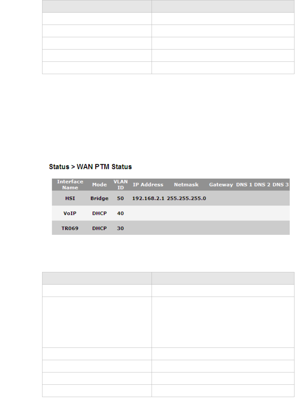
WAN PTM Status
This menu shows the WAN packet transfer Mode (PTM) status and data.
Select WAN PTM Status in the Status menu to access the WAN PTM Status window; see
Figure 4-2.
Figure 4-2 WAN PTM Status window
Table 4-2 describes the fields of the WAN PTM Status window.
Table 4-2 Field descriptions
LAN NetMask The subnet mask of the LAN IP address.
LAN MAC The MAC address of the LAN interface.
DHCP Enable DHCP handling method at LAN device.
WLAN MAC The MAC address of the WLAN interface.
WLAN SSID The SSID used to identify the CellPipe 7130 RG.
Field Description
Field Description
Interface Name The name assigned to this connection.
Mode The connection mode:
•Static IP
•DHCP
•PPPoE
•Bridge
VLAN ID The VLAN ID number from 0 to 4094.
IP Address The IP address of the connection.
Netmask The subnet mask of the IP address.
Gateway The IP address of the gateway.
............................................................................................................................................................................................................................................................
DSL Link StatusStatus
4-4 3EQ-10280-AAAA-TCZZA
Edition 01 February 2011
............................................................................................................................................................................................................................................................
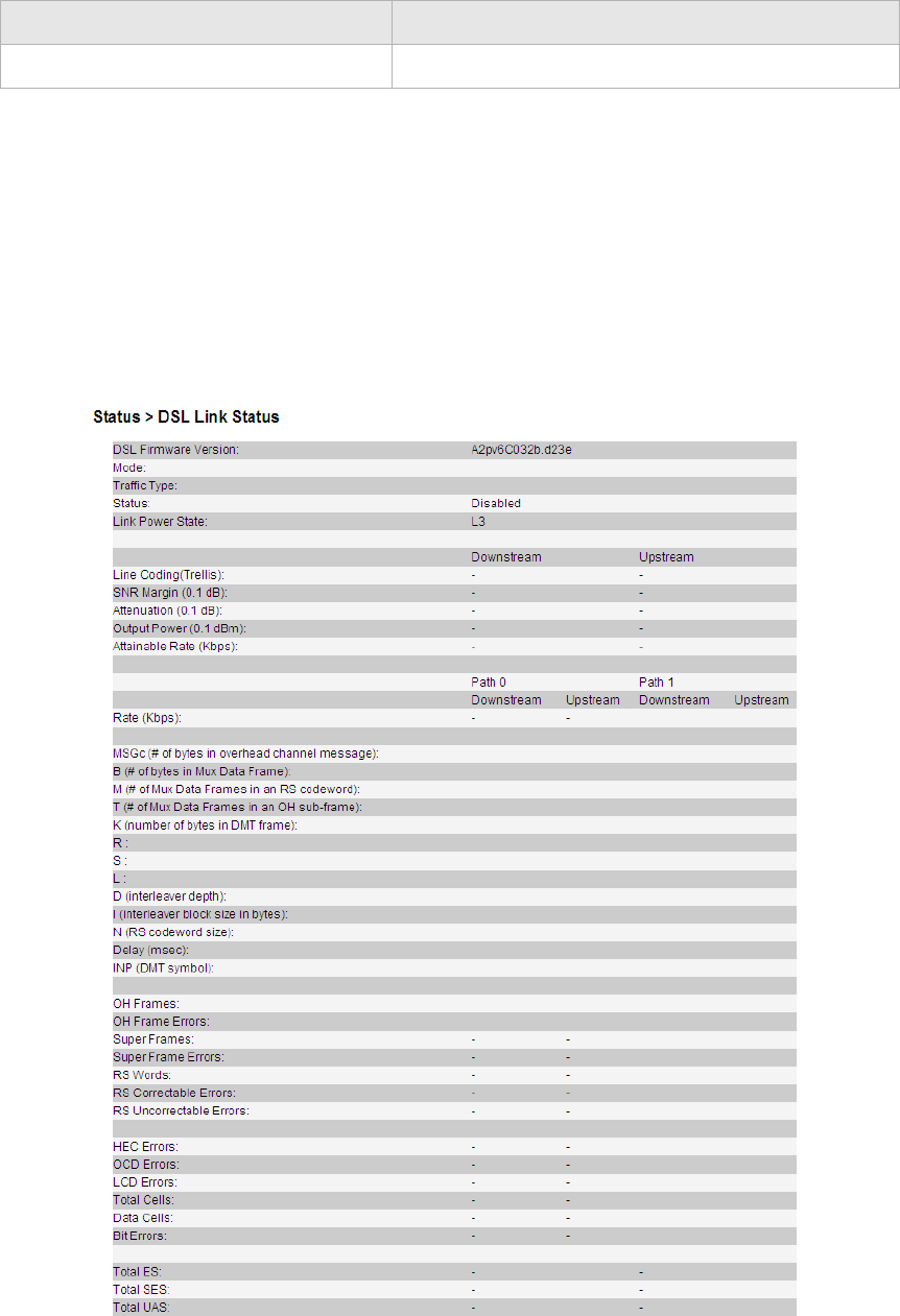
DSL Link Status
The DSL Link Status window shows the DSL connection status and data.
Select DSL Link Status in the Status menu to access the DSL Link Status window; see
Figure 4-3.
Figure 4-3 DSL Link Status window
Table 4-3 describes the fields of the DSL Link Status window.
DNS 1 to 3 The IP address of the DNS.
Field Description

StatusDSL Link Status
............................................................................................................................................................................................................................................................
3EQ-10280-AAAA-TCZZA
Edition 01 February 2011 4-5
............................................................................................................................................................................................................................................................
Table 4-3 Field descriptions
Field Description
DSL Firmware Version The version of firmware in use.
Mode The modulation protocol
Traffic Type The channel type
Status This is the status of the DSL link.
Link Power State Displays the power management state of the DSL
connection.
Line Coding (Trellis) The Trellis Coding status of downstream and
upstream.
SNR Margin(0.1dB) This is a signal-to-noise ratio (SNR) margin for
traffic going in both directions.
Atternuation(0.1dB) An estimate of the average loop attenuation
downstream and upstream.
Output Power(0.1dBm) The total output power in both directions.
Attainable Rate (Kbps): This is the maximum achievable downstream rate.
Rate (Kbps) The actual rate at which data is flowing in both
directions.
MSGc (# of bytes in overhead channel
message)
Number of bytes in overhead channel message
B (# of bytes in Mux Data Frame) Number of bytes in Mux Data Frame
M (# of Mux Data Frames in an RS
codeword)
Number of Mux Data Frames in FEC Data Frame
T (# of Mux Data Frames in a OH sub-
frame)
Mux Data Frames over sync bytes
K (number of bytes in DMT frame) This is the number of data bytes in an DSL data
frame.
R The number of redundant check bytes per Reed-
Solomon code word.
S The length of the Reed-Solomon code word, in data
frames.
L Number of bits in PMD Data Frame
D (interleabver depth) The interleaver depth.
I (interleaver block size in bytes) Number of bytes in interleaver block size
N (RS codeword size) The size of RS codeword.
Delay (msec) The delay, in microseconds, of the DSL connection.

............................................................................................................................................................................................................................................................
Device TableStatus
4-6 3EQ-10280-AAAA-TCZZA
Edition 01 February 2011
............................................................................................................................................................................................................................................................
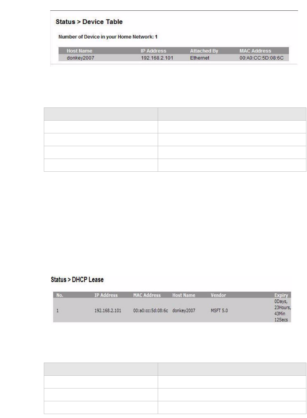
Device Table
The Device Table shows information about the devices that have connected to the
CellPipe 7130 RG.
Select Device Table in the Status menu to access the Device Table; see Figure 4-4.
INP (DMT symbol) INP:Impulse Noise Protection DMT:Discrete Multi-
tone
OH Frames The number of overhead frames.
OH Frame Errors The number of overhead frame errors.
Super Frames This is the total number of super frames.
Super Frame Errors The number of super frames received that had
errors.
RS Words This is the total number of Reed-Solomon code
words.
RS Correctable Errors The number of Reed-Solomon code words with
correctable errors.
RS Uncorrectable Errors The number of R-S code words that had
uncorrectable errors.
HEC Errors The total number of header error checksum errors.
OCD Errors The number of out-of-cell delineation errors.
LCD Errors The total of lost-cell-delineation errors.
Total Cells Total number of cells.
Data Cells The number of data cells.
Bit Errors The number of Bit Error.
Total ES Total number of Errored Seconds.
Total SES Total number of Severely Errored Seconds.
Total UAS Total number of Unavailable Seconds.
Field Description
StatusDHCP Lease
............................................................................................................................................................................................................................................................
3EQ-10280-AAAA-TCZZA
Edition 01 February 2011 4-7
............................................................................................................................................................................................................................................................
Figure 4-4 Device Table
Table 4-4 describes the fields of the Device Table window.
Table 4-4 Field descriptions
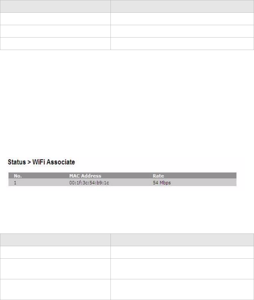
DHCP Lease
The DHCP Lease window lists the IP addresses leased to the DHCP clients in the LAN
environment.
Select DHCP Lease in the Status menu to access the DHCP Lease window; see
Figure 4-5.
Figure 4-5 DHCP Lease window
Table 4-5 describes the fields of the DHCP Lease window.
Table 4-5 Field descriptions
Field Description
Host Name The name of the device connected to the gateway.
IP Address The IP address assigned to the device.
Attached By Method used to connect to the gateway.
MAC Address The MAC address of the attached device.
Field Description
No. The index number of the entry in the table.
IP Address The IP address leased to the LAN device.
MAC Address The MAC address of the LAN device.
............................................................................................................................................................................................................................................................
WiFi AssociationStatus
4-8 3EQ-10280-AAAA-TCZZA
Edition 01 February 2011
............................................................................................................................................................................................................................................................
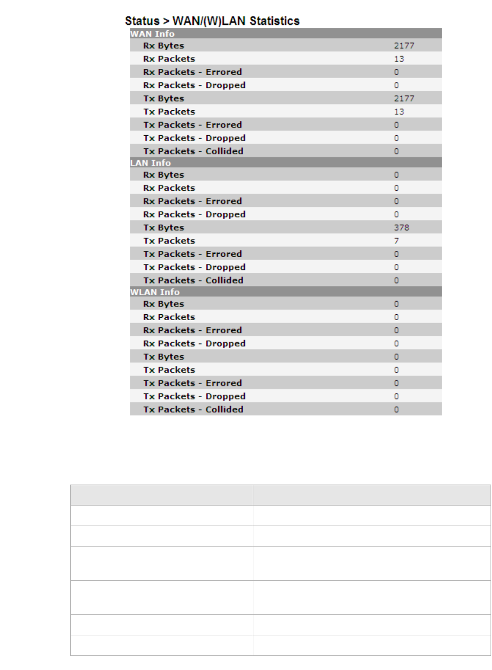
WiFi Association
The WiFi Association window lists the wireless clients that are currently connected to the
CellPipe 7130 RG.
Select WiFi Association in the Status menu to access the WiFi Association window; see
Figure 4-6.
Figure 4-6 WiFi Association window
Table 4-6 describes the fields of the WiFi Association window.
Table 4-6 Field descriptions
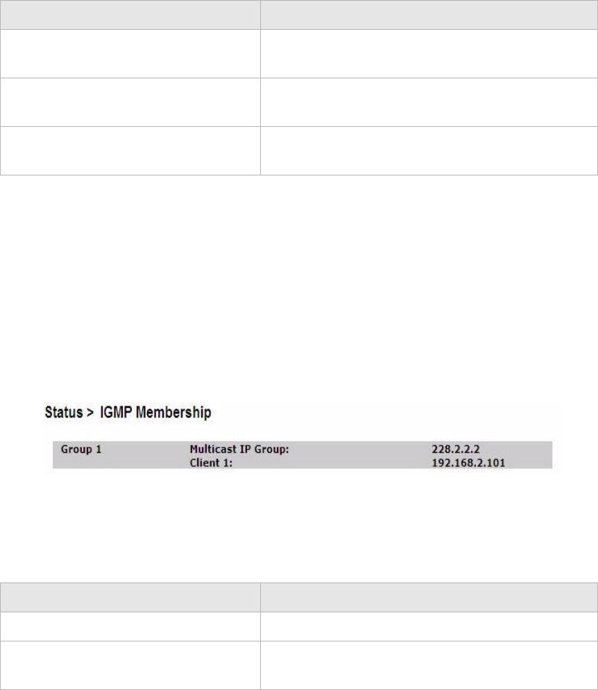
WAN/(W)LAN Statistics
The WAN/(W)LAN Statistics window shows the number of bytes that have been received
or transmitted by the WAN, LAN, and WLAN interfaces.
Select WAN/(W)LAN Statistics in the Status menu to access the WAN/(W)LAN Statistics
window; see Figure 4-7.
Host Name The host name of the DHCP client.
Vendor The platform of the DHCP client.
Expiry The time remaining before the lease expires.
Field Description
Field Description
No. The index number of the entry.
MAC Address The MAC address of the wireless device connected
to the CellPipe 7130 RG.
Rate The transmission rate of the wireless device
connected to the CellPipe 7130 RG.
StatusWAN/(W)LAN Statistics
............................................................................................................................................................................................................................................................
3EQ-10280-AAAA-TCZZA
Edition 01 February 2011 4-9
............................................................................................................................................................................................................................................................
Figure 4-7 WAN/(W)LAN Statistics window
Table 4-7 describes the fields of the WAN/(W)LAN Statistics window.
Table 4-7 Field descriptions
Field Description
Rx Bytes The number of bytes that have been received.
Rx Packets The number of packets that have been received.
Rx Packets-Errored The number of packets that have been received with
errors.
Rx Packets-Dropped The number of packets that have been dropped after
being received.
Tx Bytes The number of bytes that have been transmitted.
Tx Packets The number of packets that have been transmitted.
............................................................................................................................................................................................................................................................
IGMP MembershipStatus
4-10 3EQ-10280-AAAA-TCZZA
Edition 01 February 2011
............................................................................................................................................................................................................................................................
IGMP Membership
The IGMP Membership window shows the IGMP members.
Select IGMP Membership in the Status menu to access the IGMP Membership window;
see Figure 4-8.
Figure 4-8 IGMP Membership window
Table 4-8 describes the fields of the IGMP Membership window.
Table 4-8 Field descriptions
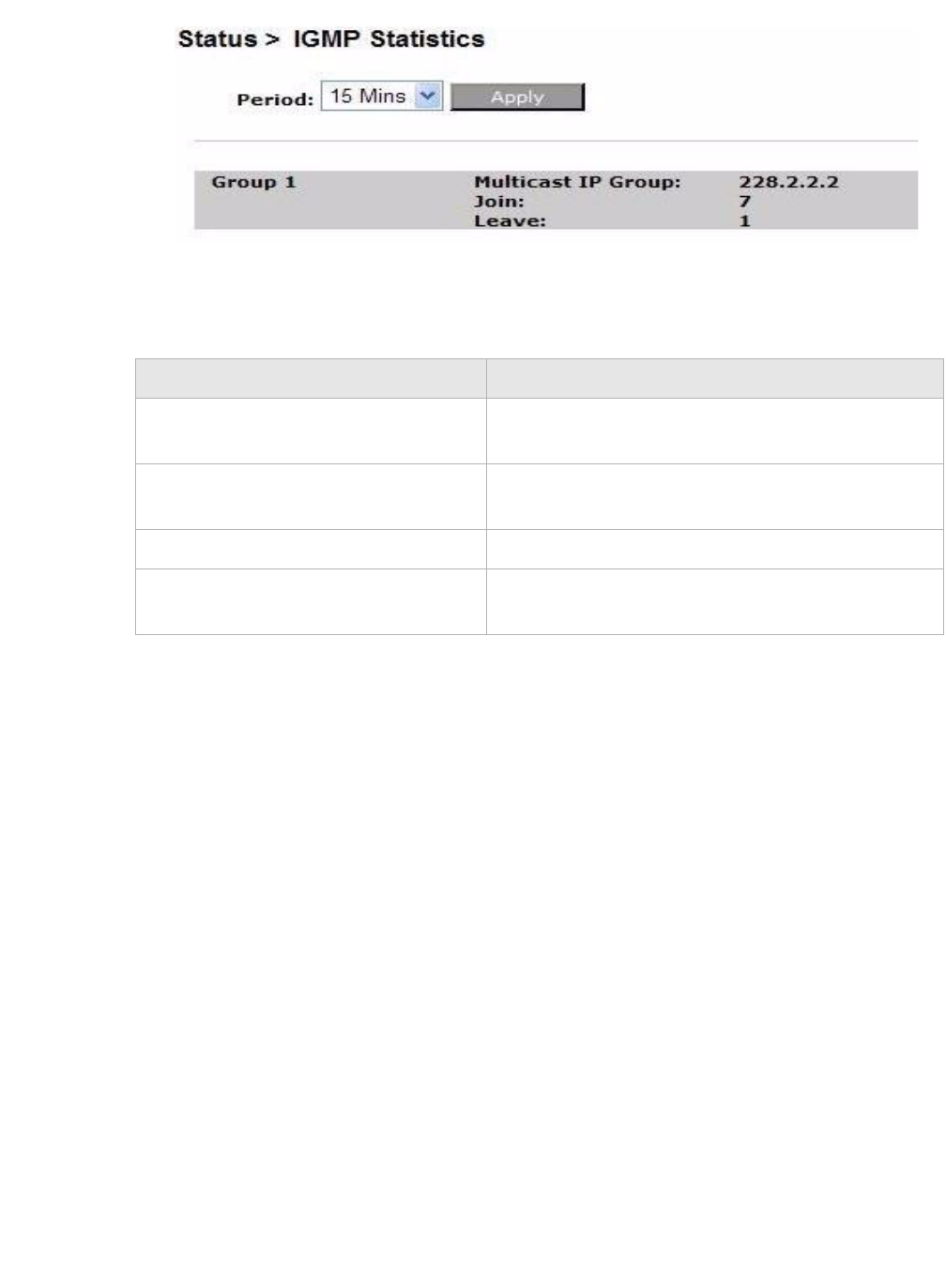
IGMP Statistics
The IGMP Statistics window shows the IGMP statistics.
Note: This window only shows the IGMP activity statistics for each group within
the time period you have set.
Select IGMP Statistics in the Status menu to access the IGMP Statistics windows; see
Figure 4-9.
Tx Packets-Errored The number of packets that have been transmitted
with errors.
Tx Packets-Dropped The number of packets that have been dropped after
being transmitted.
Tx Packets-Collided The number of packets that collided when
transmitted.
Field Description
Field Description
Multicast IP Group The multicast group.
Client Lists the IP address of the client in the specific
multicast group.
Status
............................................................................................................................................................................................................................................................
3EQ-10280-AAAA-TCZZA
Edition 01 February 2011 4-11
............................................................................................................................................................................................................................................................
Figure 4-9 IGMP Statistics window
Table 4-9 describes the fields of the IGMP Statistics window.
Table 4-9 Field descriptions
Field Description
Period Select a time period in minutes to collect and display
the IGMP statistics.
Apply Click to show the IGMP group information for the
selected time period.
Join Number of clients in the IGMP group domain.
Leave Number of clients that have left the IGMP group
domain.
............................................................................................................................................................................................................................................................
Status
4-12 3EQ-10280-AAAA-TCZZA
Edition 01 February 2011
............................................................................................................................................................................................................................................................

5-1
3EQ-10280-AAAA-TCZZA
Edition 01 February 2011
............................................................................................................................................................................................................................................................
5Network
Overview
Purpose
This chapter explains how to configure the network settings for the CellPipe 7130 RG.
Click the Network in the main menu to open the Network menu.
Contents
This chapter covers the following topics:
USB
The USB windows allows you to configure services using the USB 2.0 interface. On the
USB 2.0 interface, the following devices can be connected: Printer, storage device, sensor
network interface.
By enabling the printerserver service "USB printer", you can print via your home network
to this printer. By connecting a storage devices, the gateway can be used as fileserver.
When enabling the DMS service, all digital media on the storage device will become
available on your home network. (UPnP AV)
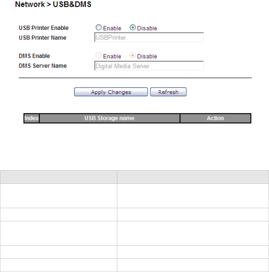
Select USB in the Network menu to access the USB&DMS window; see Figure 5-1.
USB 5-1
LAN Settings 5-3
WAN Link Selection 5-6
WAN PTM Connections 5-6
............................................................................................................................................................................................................................................................
USBNetwork
5-2 3EQ-10280-AAAA-TCZZA
Edition 01 February 2011
............................................................................................................................................................................................................................................................
Figure 5-1 USB&DMS window
Table 5-1 describes the fields of the USB&DMS window.
Table 5-1 Field descriptions
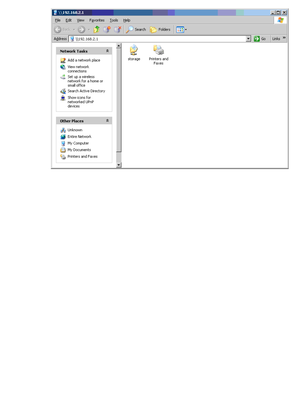
Connecting storage device
When a storage device is connected, this storage can be accessed via the LAN (Home
network) and can not be accessed from the WAN side due to security reasons. The
following file-systems are supported : FAT16, FAT32, NTFS, EXT2, EXT3. No access
rights can be set, neither user accounts.
For windows, the filesharing can be access by opening the internet explorer and typing the
IP address of the gateway. The default IP address is \\192.168.2.1\ The default userid and
password are used : guest / guest
Field Description
USB Enable Select Enable to enable USB.
Select Disable to disable USB.
USB Printer Name Enter a USB printer name.
DMS Enable Select Enable to enable DMS.
Select Disable to disable DMS.
DMS Server Name Enter a DMS Server name.
Apply Changes Click to save your changes.
NetworkLAN Settings
............................................................................................................................................................................................................................................................
3EQ-10280-AAAA-TCZZA
Edition 01 February 2011 5-3
............................................................................................................................................................................................................................................................
Figure 5-2 Connecting storage device
Note:
•DMS works only for devices which are directly connected to the LAN interface of the
gateway.
•The content cannot be reached from the WAN interface.
•DMS only works when an storage devices is connected to the USB 2.0 interface.
•The DMS will support UMLAUT characters
•The following file systems will be supported: FAT16, FAT32, NTFS, EXT2, EXT3
via USB
WARNING
When a storage (USB-harddisk or USB memory stick) is connected to the gateway, the
content will be automatically be available on your home network and accessible by
everybody on that home network.
If the DMS function is enabled, the gateway discovers all digital media on the connected
storage device (Harddisk/USB-memory-stick) and make this accessible via PnP AV
protocol.
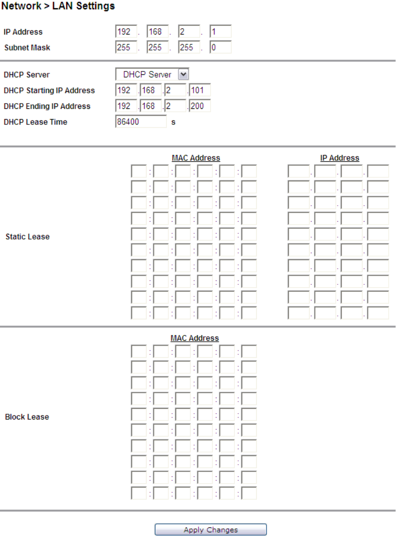
LAN Settings
The LAN Settings window enables you to configure the IP address, subnet mask, DHCP
settings, DHCP relay, and static IP lease.
............................................................................................................................................................................................................................................................
LAN SettingsNetwork
5-4 3EQ-10280-AAAA-TCZZA
Edition 01 February 2011
............................................................................................................................................................................................................................................................
Select LAN Settings in the Network menu to access the LAN Settings window; see
Figure 5-3.
Figure 5-3 LAN Settings window - DHCP Server option selected
Table 5-2 describes the fields of the LAN Settings window.

NetworkLAN Settings
............................................................................................................................................................................................................................................................
3EQ-10280-AAAA-TCZZA
Edition 01 February 2011 5-5
............................................................................................................................................................................................................................................................
Table 5-2 Field descriptions
Field Description
IP Address The IP address of the LAN interface in dotted
decimal notation. The default is 192.168.2.1. You
can change this address as necessary to any address
that is reserved for private use.
Subnet Mask The subnet mask of the IP addresses in your LAN;
for example, 255.255.255.0.
DHCP Server Select DHCP Server to enable DHCP server. The
CellPipe 7130 RG automatically assigns the IP
addresses, default gateway, and DNS servers to
computers that support the DHCP client; for
example, Windows 95 or Windows NT.
Select DHCP Relay to enable DHCP Relay.
Select Disable to disable DHCP server.
Note: Figure 5-2 shows the DHCP Server options.
Selecting DHCP Relay will open the DHCP Relay
server options.
DHCP Relay Server 1 Enter the IP address of the DHCP server.(DHCP
Relay)
DHCP Relay Server 2 Enter the IP address of the second DHCP server for
a different service, if applicable.(DHCP Relay)
Mapping Vendor ID Enter the Vendor ID for DHCP Option 60. When the
client sends a DHCP request that contains vendor ID
is equal to the Vendor ID, the request will be sent to
"DHCP Relay Server 2". (DHCP Relay)
DHCP Starting IP Address
DHCP Ending IP Address
The range of IP addresses that will be assigned to the
DHCP client.
DHCP Lease Time The time period during which the computers retain
the IP addresses assigned to them.
Static Lease Assign a static IP address to DHCP clients based on
their MAC address.
Block Lease The MAC address of the client to block from
acquiring an IP address.
Apply Changes Click to save your changes.
............................................................................................................................................................................................................................................................
WAN Link SelectionNetwork
5-6 3EQ-10280-AAAA-TCZZA
Edition 01 February 2011
............................................................................................................................................................................................................................................................
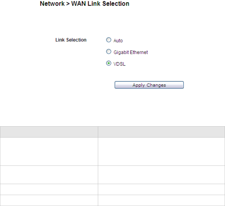
WAN Link Selection
The WAN Link Selection window specifies which link will be used for the WAN
connection, one of auto-dedicate mode, Gigabit Ethernet, or DSL.
Note: You must reboot the CellPipe 7130 RG to switch from one WAN interface to
another.
Select WAN Link Selection in the Network menu to access the WAN Link Selection
window; see Figure 5-4.
Figure 5-4 WAN Link Selection window
Table 5-3 describes the fields of the WAN Link Selection window.
Table 5-3 Field descriptions
WAN PTM Connections
WAN PTM connections are the connections used when the device operates in DSL-PTM
mode (if you are uncertain whether your DSL service is PTM, contact your ISP). The
WAN PTM Connections window enables you to configure multiple connections.
Field Description
Auto Select to automatically detect the WAN link.
Note: Only one of the two LAN ports should be
physically connected.
Gigabit Ethernet Select to use only the Gigabit Ethernet port as the
WAN link.
VDSL Select to use the VDSL port.
Apply Changes Click to save your changes.

NetworkWAN PTM Connections
............................................................................................................................................................................................................................................................
3EQ-10280-AAAA-TCZZA
Edition 01 February 2011 5-7
............................................................................................................................................................................................................................................................
CAUTION
It is recommended that the WAN PTM connections be changed by trained service
personnel. Improper configuration can lead to loss of connectivity to the residential
gateway from the LAN side as well as the WAN side.
There are three different binding methods for the connections:
•Port based binding
•MAC based binding
•No LAN/WLAN binding
The four following types of connections can be used:
•Static IP
•DHCP Mode
•PPPoE Mode
•Bridge Mode
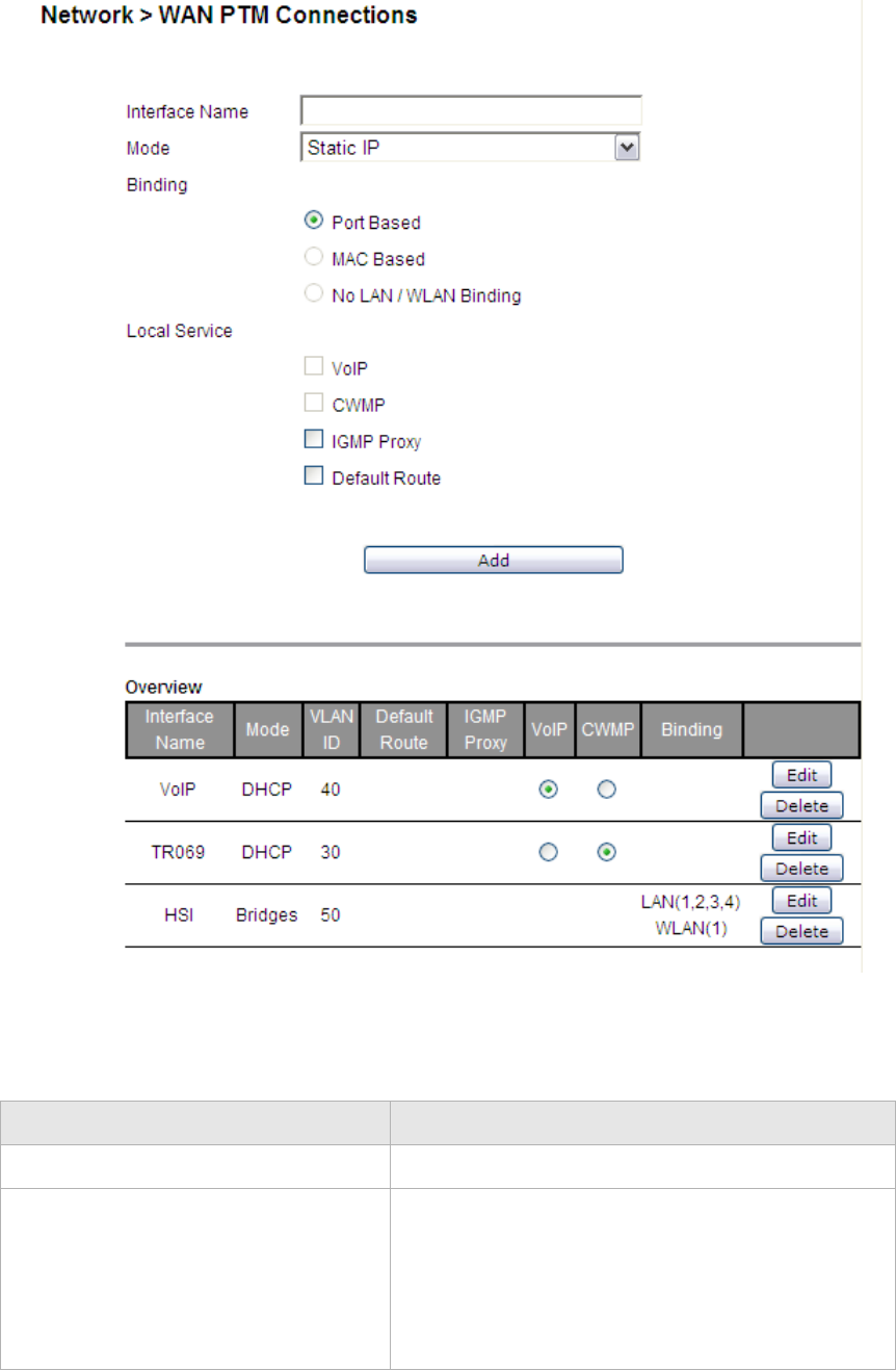
Select WAN PTM Connections in the Network menu to access the WAN PTM
Connections window; see Figure 5-5.
............................................................................................................................................................................................................................................................
WAN PT M ConnectionsNetwork
5-8 3EQ-10280-AAAA-TCZZA
Edition 01 February 2011
............................................................................................................................................................................................................................................................
Figure 5-5 WAN PTM Connections window
Table 5-4 describes the fields of the WAN PTM Connections window.
Table 5-4 Field descriptions
Field Description
Interface Name Enter a name for your new connection.
Mode Select a mode for the connection type:
•Static IP
•DHCP
•PPPoE
•Bridge

NetworkWAN PTM Connections
............................................................................................................................................................................................................................................................
3EQ-10280-AAAA-TCZZA
Edition 01 February 2011 5-9
............................................................................................................................................................................................................................................................
Binding Select a binding method:
•Port Based to bind traffic to the connection by
LAN or WLAN port.
•MAC Based to bind traffic to the connection by
MAC address.
•No LAN/WLAN Binding so that the connection
does not bind traffic to any port or MAC.
Note: You cannot use a combination of Port based
and MAC based binding.
Note: When using MAC based binding, you must
define a Default connection first. This default
connection can be a routed or bridged connection.
After defining the default MAC based connection,
you can add extra bridged (not routed) connections
which are selected on basis of configurable MAC
layer based criteria.
Local Service Enable a local service:
•Enable VoIP to provide VoIP service.
•Enable CWMP to provide remote control
service. It allows a remote server to manage the
gateway
•Enable IGMP Proxy to provide service to be
used for video streaming and gaming.
•Enable Default Route to set the connection as
the gateway of last resort.
Add Click to add the new connection and proceed to the
next configuration window.
Note: After adding new connections, click
Activate WAN Settings to activate the connection.
This button will be only visible if you added a new
connection or made changes to the settings.
Interface Name (read-only) The name of the interface.
Mode (read-only) The selected mode.
VLAN ID (read-only) The VLAN ID.
Default Route All connections will be routed via the default route,
except for the connection that has special routing.
There can be only one default route between all the
connections.
IGMP Proxy Select the interface to support IGMP service.
VoIP Select the interface to support VoIP service.
CWMP Select the interface to support CWMP service.
Field Description

............................................................................................................................................................................................................................................................
WAN PT M ConnectionsNetwork
5-10 3EQ-10280-AAAA-TCZZA
Edition 01 February 2011
............................................................................................................................................................................................................................................................
Port based binding
Port based mode enables you to bind ports to your WAN connection. You can bind LAN
ports 1 to 4 and WLAN SSID 1 to 4 in the WAN mode you selected. The default WLAN
SSID number is 1 and you can configure 2 to 4 in the WiFi Settings.
You can select the Port Based radio button for each WAN mode and then click Add to
proceed to the next configuration window.
In Port based mode, you can add up to four connections in routed mode.
Note: If you do not set a VLAN ID in the connections, you can only have one
connection in Static IP or DHCP mode and three connections maximum in PPPoE.
Note: If you already have a connection with Port based binding, you can not select
MAC based binding for any other connections.
The following WAN modes support port-based binding:
•Static IP
•DHCP
•PPPoE
•Bridge
Static IP
If you select Static IP as the mode in the WAN PTM Connections, the Static IP settings
window with Port based binding opens; see Figure 5-6.
Binding (read-only) Shows which ports or MAC addresses are bound on
the connection.
Delete All Click to delete all the connections.
Edit Click to modify the settings of the connection.
After changing the connection settings, press
Activate WAN Settings to activate the connection.
This button will be only visible if you made changes
to the settings or added a new connection.
Delete Click to delete the connection.
Field Description
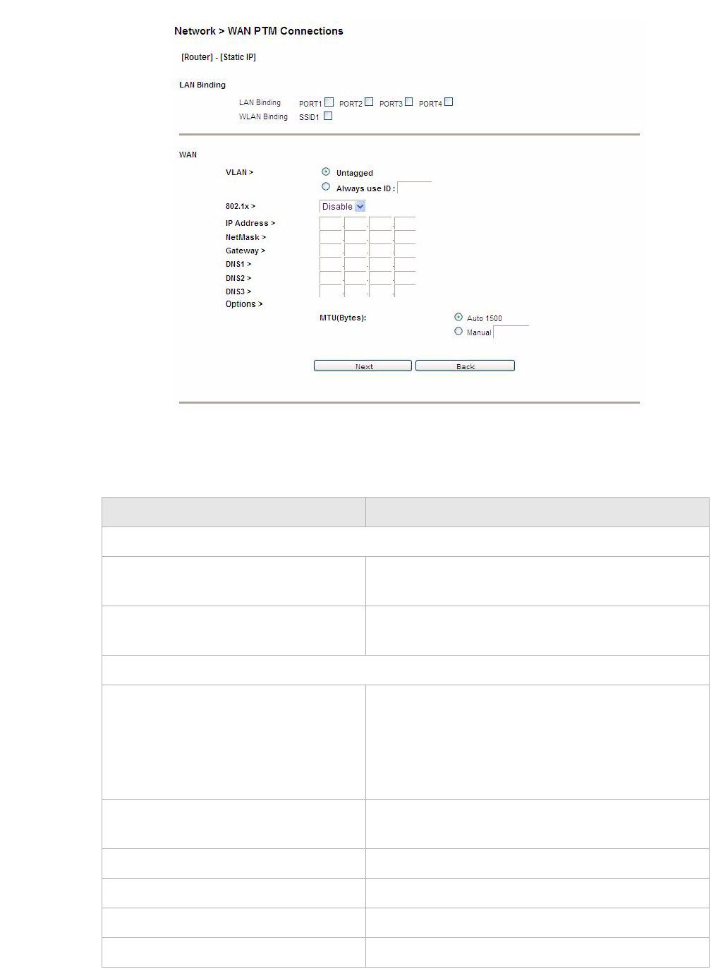
NetworkWAN PTM Connections
............................................................................................................................................................................................................................................................
3EQ-10280-AAAA-TCZZA
Edition 01 February 2011 5-11
............................................................................................................................................................................................................................................................
Figure 5-6 Static IP settings window with Port based binding
Table 5-5 describes the fields of Static IP settings window with Port based binding.
Table 5-5 Field descriptions
Field Description
LAN Binding
LAN Binding Select the port to which you want to bind the
connection.
WLAN Binding Select the SSID to which you want to bind the
connection.
WAN
VLAN Select Untagged if VLAN tagging is not to be used
for this WAN connection.
Select Always use ID if VLAN tagging is to be
used and enter the VLAN ID number (between 0 and
4094).
802.1X Select Enable to use 802.1x or select Disable to
turn off 802.1x.
IP Address Enter the IP address provided by your ISP.
NetMask Enter the subnet mask provided by your ISP.
Gateway Enter the gateway IP address provided by your ISP.
DNS1 to 3 Enter the DNS IP address (these are optional).
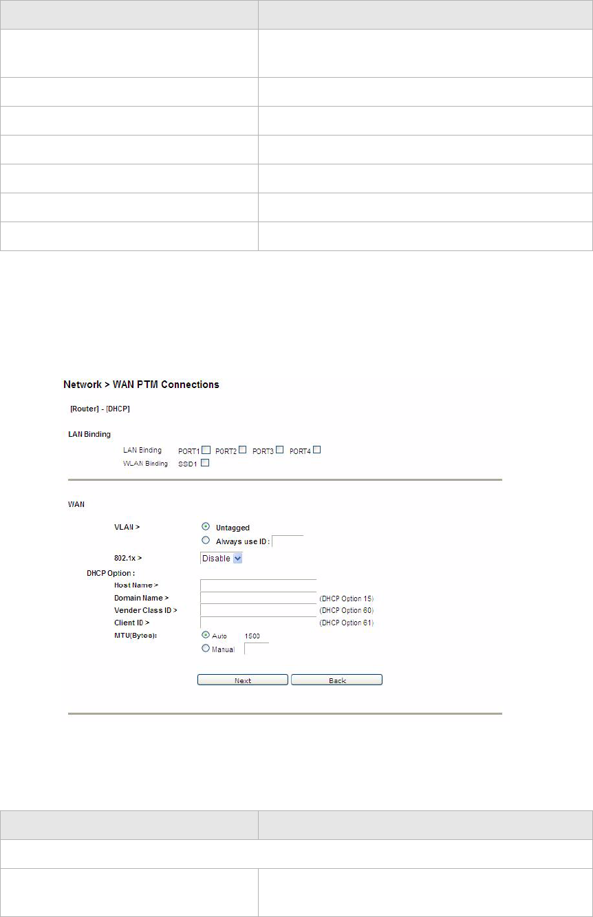
............................................................................................................................................................................................................................................................
WAN PT M ConnectionsNetwork
5-12 3EQ-10280-AAAA-TCZZA
Edition 01 February 2011
............................................................................................................................................................................................................................................................
DHCP
If you select DHCP as the mode in the WAN PTM Connections window, the DHCP settings
window with Port based binding opens; see Figure 5-7.
Figure 5-7 DHCP settings window with Port based binding
Table 5-6 describes the fields of DHCP settings window with Port based binding.
Table 5-6 Field descriptions
MTU(Bytes) Select Auto to set the MTU to the default (1500) or
select Manual and enter a value in bytes.
Next Click to go to the QoS Defaults window.
Back Click to return to the previous window.
Activate WAN Setting Click to activate the connection.
Delete All Click to remove all WAN connections.
Edit Click to make changes to a specific connection.
Delete Click to remove a specific connection.
Field Description
LAN Binding
LAN Binding Select the port to which you want to bind the
connection.
Field Description

NetworkWAN PTM Connections
............................................................................................................................................................................................................................................................
3EQ-10280-AAAA-TCZZA
Edition 01 February 2011 5-13
............................................................................................................................................................................................................................................................
PPPoE
If you select PPPoE as the mode in the WAN PTM Connections window, the PPPoE
settings window with Port based binding opens; see Figure 5-8.
WLAN Binding Select the SSID to which you want to bind the
connection.
WAN
VLAN Select Untagged if VLAN tagging is not to be used
for this WAN connection.
Select Always use ID if VLAN tagging is to be
used and enter the VLAN ID number (between 0 and
4094).
802.1X Select Enable to use 802.1x or select Disable to
turn off 802.1x.
Host Name Enter the host name provided by your ISP. If you are
unsure of the host name, please consult with your
ISP for more information.
Domain Name Enter the domain name provided by your ISP. If you
are unsure of the domain name, please consult with
your ISP for more information.
Vender Class ID If required, set the vender class ID to obtain its lease
from the DHCP server. Please consult with your ISP
for more information.
Client ID If required, set the client ID to obtain its lease from
the DHCP server. Please consult with your ISP for
more information.
MTU(Bytes) Select Auto to set the MTU to the default (1500) or
select Manual and enter a value in bytes.
Activate WAN Setting Click to activate the connection.
Delete All Click to remove all WAN connections.
Edit Click to make changes to a specific connection.
Delete Click to remove a specific connection.
Next Click to go to the QoS Defaults window.
Back Click to return to the previous window.
Field Description
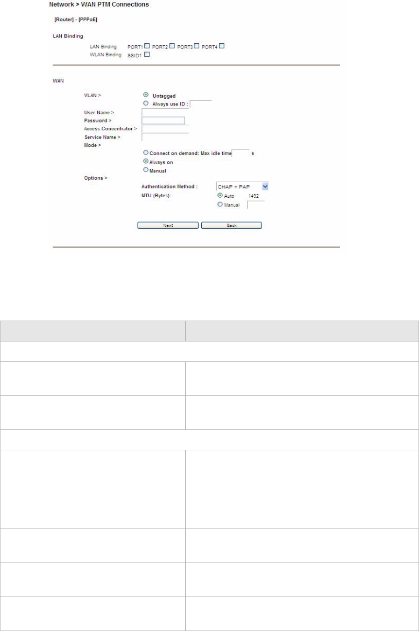
............................................................................................................................................................................................................................................................
WAN PT M ConnectionsNetwork
5-14 3EQ-10280-AAAA-TCZZA
Edition 01 February 2011
............................................................................................................................................................................................................................................................
Figure 5-8 PPPoE settings window with Port based binding
Table 5-7 describes the fields of PPPoE settings window with Port based binding.
Table 5-7 Field descriptions
Fields Description
LAN Binding
LAN Binding Select the port to which you want to bind the
connection.
WLAN Binding Select the SSID to which you want to bind the
connection.
WAN
VLAN Select Untagged if VLAN tagging is not to be used
for this WAN connection.
Select Always use ID if VLAN tagging is to be
used and enter the VLAN ID number (between 0
and 4094).
User Name Enter the username for the PPPoE connection.
Please consult with your ISP for more information.
Password Enter the password for the PPPoE connection.
Please consult with your ISP for more information.
Access Concentrator The access concentrator is optional. Please consult
with your ISP for information.

NetworkWAN PTM Connections
............................................................................................................................................................................................................................................................
3EQ-10280-AAAA-TCZZA
Edition 01 February 2011 5-15
............................................................................................................................................................................................................................................................
Bridge
If you select Bridge as the mode in the WAN PTM Connections window, the Bridge
settings window with Port based binding opens; see Figure 5-9.
Service Name The service name is optional. Please consult with
your ISP for information.
Mode Select the mode:
•Select Connect on demand to allow the
gateway to connect to the Internet only when
you are trying to access it. Enter a Max idle
time. If there are no activities in the specified
time period, the CellPipe 7130 RG will
disconnect the connection.
•Select Always on to set the CellPipe 7130 RG
to always connect to the Internet.
•Select Manual and then click Connect to
manually connect the CellPipe 7130 RG to the
Internet. Click Disconnect to disconnect the
connection.
Authentication Method Select the authentication mode:
•CHAP + PAP
•Only MS-CHAP
•Only CHAP
•Only PAP
This is optional. Please consult with your ISP for
more information.
MTU (Bytes) Select Auto to set the MTU to the default (1492) or
select Manual and enter a value in bytes.
Activate WAN Setting Click to activate the connection.
Delete All Click to remove all WAN connections.
Edit Click to make changes to a specific connection.
Delete Click to remove aspecific connection
Next Click to go to the QoS Defaults window.
Back Click to return to the previous window.
Fields Description
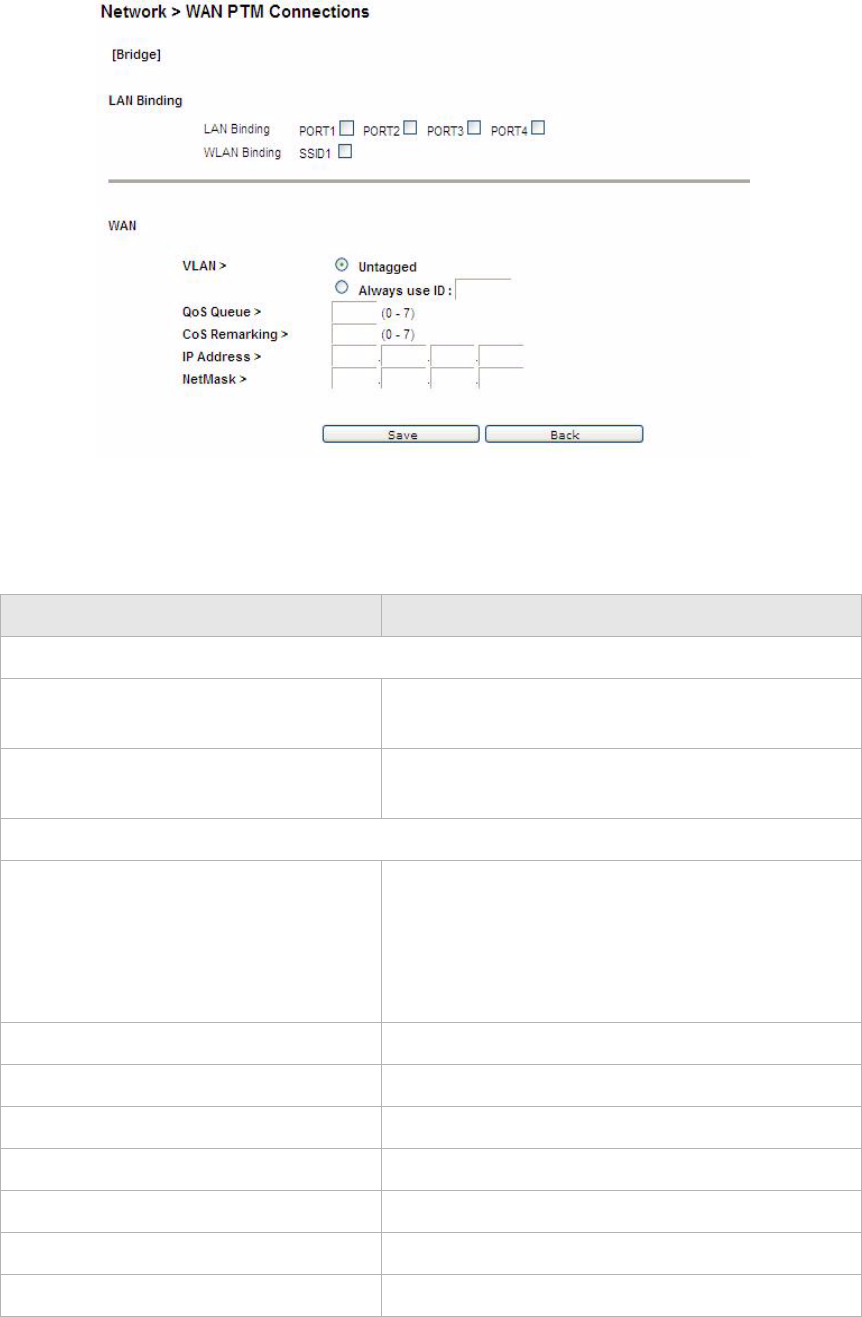
............................................................................................................................................................................................................................................................
WAN PT M ConnectionsNetwork
5-16 3EQ-10280-AAAA-TCZZA
Edition 01 February 2011
............................................................................................................................................................................................................................................................
Figure 5-9 Bridge settings window with Port based binding
Table 5-8 describes the fields of Bridge settings window with Port based binding.
Table 5-8 Field descriptions
Fields Description
LAN Binding
LAN Binding Select the port to which you want to bind the
connection.
WLAN Binding Select the SSID to which you want to bind the
connection.
WAN
VLAN Select Untagged if VLAN tagging is not to be
used for this WAN connection.
Select Always use ID if VLAN tagging is to be
used and enter the VLAN ID number (between 0
and 4094).
QoS Queue Enter the QoS queue number.
CoS Remarking Enter the CoS remarking number.
IP Address Enter the IP address provided by your ISP.
NetMask Enter the subnet mask provided by your ISP.
Save Click to save your changes.
Back Click to return to the previous window.
Activate WAN Setting Click to activate the connection.

NetworkWAN PTM Connections
............................................................................................................................................................................................................................................................
3EQ-10280-AAAA-TCZZA
Edition 01 February 2011 5-17
............................................................................................................................................................................................................................................................
MAC based binding
MAC based mode enables you to bind your connection by DHCP Option 60, Ethernet
type, source MAC, or destination MAC.
Before you begin, you must configure a default connection. It should be routed or bridge
mode. Afterwards you can configure MAC based binding (the other binding options are
Port based and No LAN/WLAN) by DHCP Option 60, Ethernet type, source MAC, or
destination MAC.
You can select the MAC Based radio button for each WAN mode and then click Add to
enter the next configuration window.
You can set a maximum of 20 connections in MAC based binding.
Note: If you already have a connection with MAC based binding, you cannot select
Port based binding for any other connections.
The following section shows the creation of a default DHCP connection with MAC based
binding.
DHCP
If you select DHCP as the mode, the DHCP settings window with MAC based binding
opens; see Figure 5-10.
Delete All Click to remove all WAN connections.
Edit Click to make changes to a specific connection.
Delete Click to remove aspecific connection
Fields Description
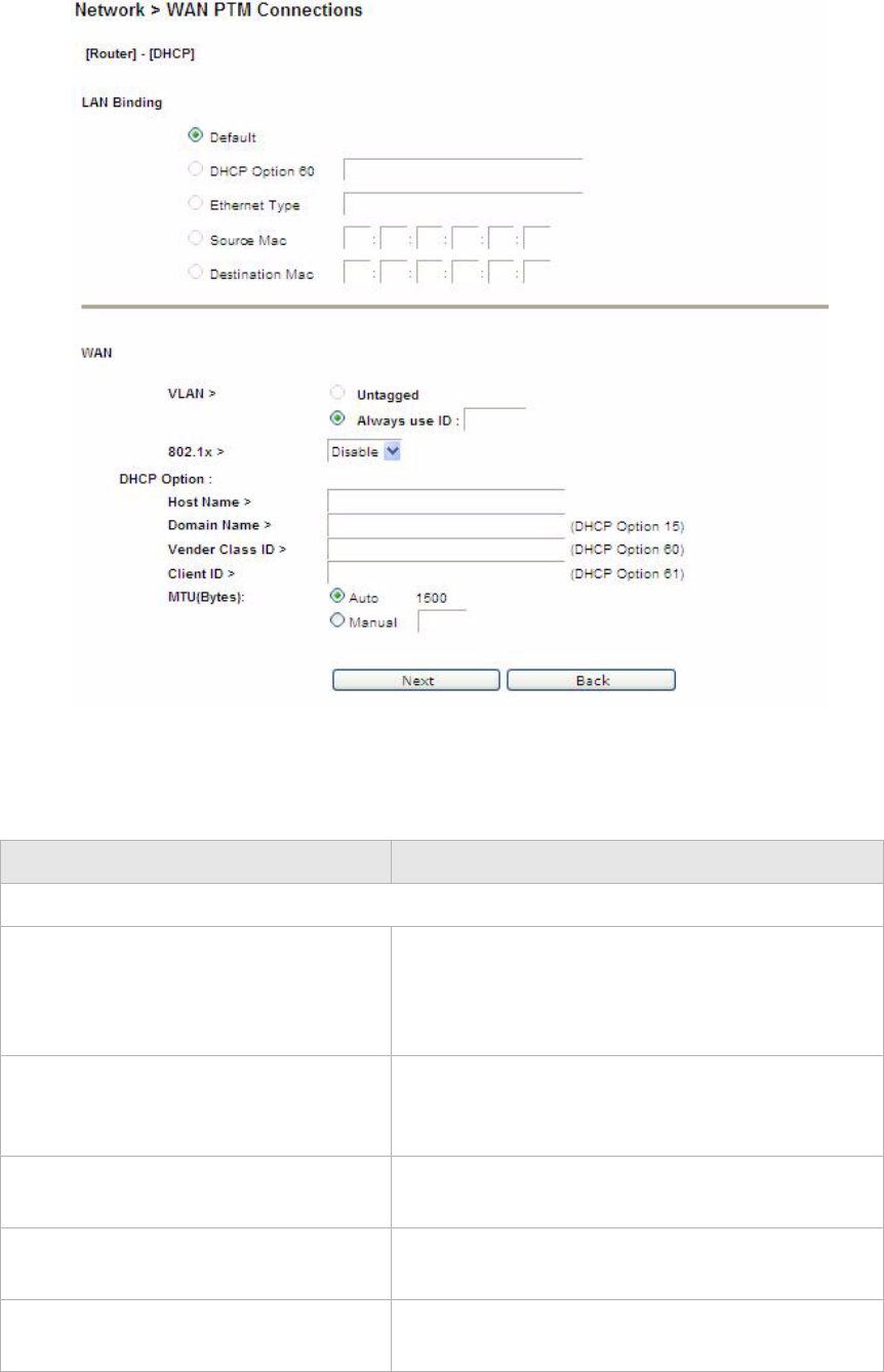
............................................................................................................................................................................................................................................................
WAN PT M ConnectionsNetwork
5-18 3EQ-10280-AAAA-TCZZA
Edition 01 February 2011
............................................................................................................................................................................................................................................................
Figure 5-10 DHCP settings window with MAC based binding
Table 5-9 describes the fields of DHCP settings window with MAC based binding.
Table 5-9 Field descriptions
Fields Description
LAN Binding
Default The first rule must be the default. After you have a
default rule you can choose the other options. For
example, you can select DHCP Option 60, Ethernet
Type, Source MAC, or Destination MAC.
DHCP Option 60 Select the radio button and enter the applicable
alphanumeric identification (wildcard * is also
applicable).
Ethernet Type Select the radio button and enter the applicable
Ethernet Type code (4 hex digits).
Source MAC Select the radio button and enter the applicable
Source MAC address in hexadecimal format.
Destination MAC Select the radio button and enter the applicable
Destination MAC address in hexadecimal format.

NetworkWAN PTM Connections
............................................................................................................................................................................................................................................................
3EQ-10280-AAAA-TCZZA
Edition 01 February 2011 5-19
............................................................................................................................................................................................................................................................
Now that you have a default connection, the WAN PTM Connections window with MAC
based binding opens; see Figure 5-11.
WAN
VLAN Select Untagged if VLAN tagging is not to be
used for this WAN connection.
Select Always use ID if VLAN tagging is to be
used and enter the VLAN ID number (between 0
and 4094).
802.1x Select Enable to use 802.1x or select Disable to
turn off 802.1x. Please consult your ISP for more
information.
Host Name Enter the host name provided by your ISP. Please
consult with your ISP for more information.
Domain Name Enter the domain name provided by your ISP.
Please consult with your ISP for more information.
Vender Class ID If you are required, set the vender class ID to obtain
its lease from the DHCP server. Please consult with
your ISP for more information.
Client ID If you are required, set the client ID to obtain its
lease from the DHCP server. Please consult with
your ISP for more information.
MTU(Bytes) Select Auto to set the MTU to the default (1500) or
select Manual and enter a value in bytes.
Next Click to go to the QoS Defaults window.
Back Click to return to the previous page.
Fields Description
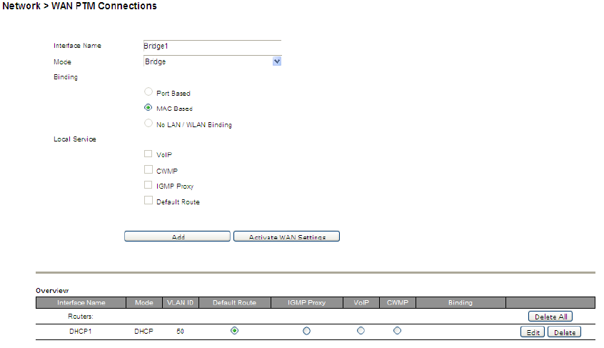
............................................................................................................................................................................................................................................................
WAN PT M ConnectionsNetwork
5-20 3EQ-10280-AAAA-TCZZA
Edition 01 February 2011
............................................................................................................................................................................................................................................................
Figure 5-11 WAN PTM Connections window with MAC based binding
After you have a default connection, you can choose the WAN Mode you want and click
Add to add a new connection. You can only choose Bridge mode with MAC based
binding. Click Add to set the configurations.
When you select Bridge mode with MAC based binding and click Add, the Bridge settings
window with MAC based binding opens; see Figure 5-12.
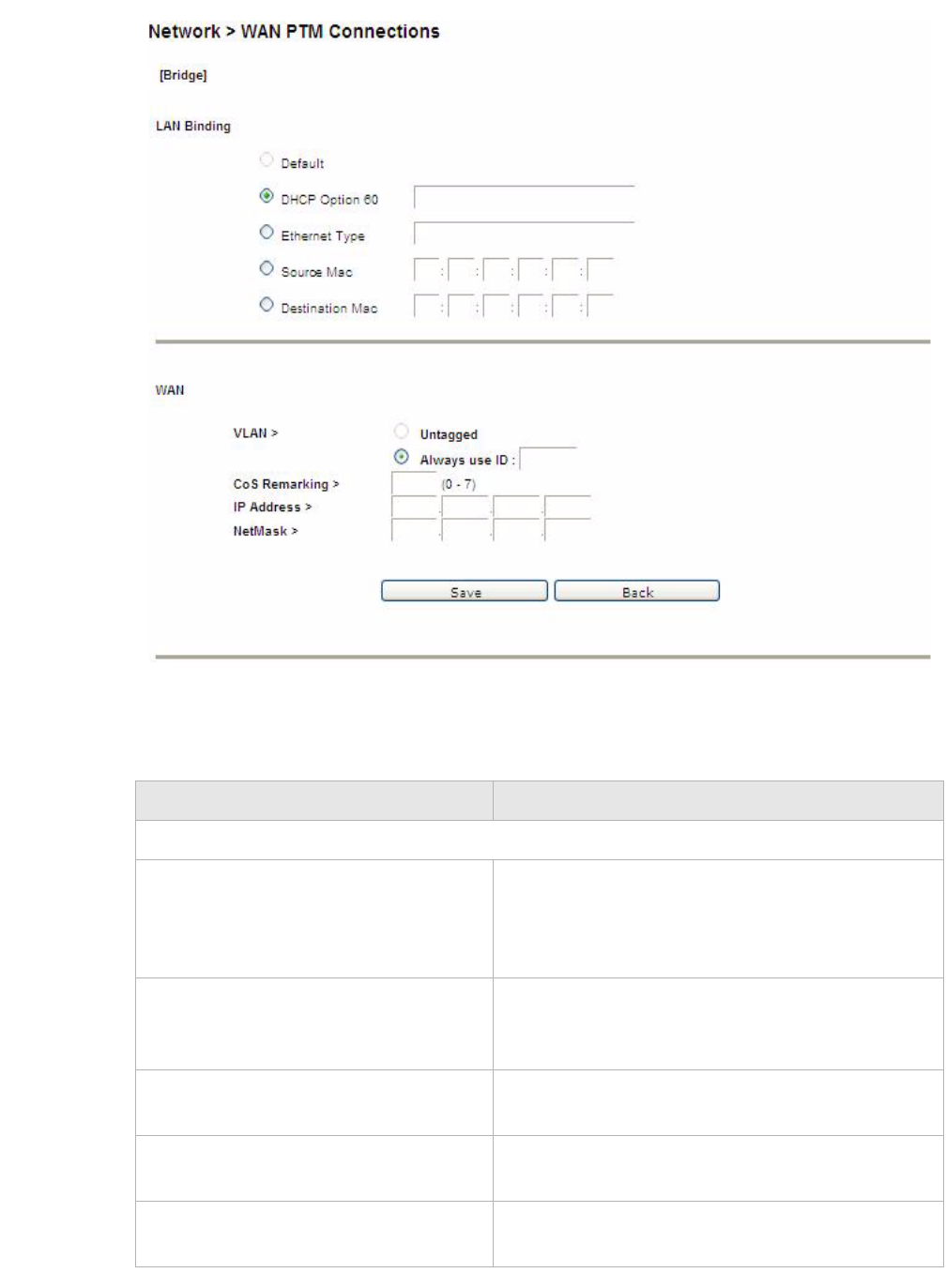
NetworkWAN PTM Connections
............................................................................................................................................................................................................................................................
3EQ-10280-AAAA-TCZZA
Edition 01 February 2011 5-21
............................................................................................................................................................................................................................................................
Figure 5-12 Bridge settings window with MAC based binding
Table 5-10 describes the fields of Bridge settings window with MAC based binding.
Table 5-10 Field descriptions
Fields Description
LAN Binding
Default The first rule must be the default. After you have a
default rule you can choose the other options. For
example, you can select DHCP Option 60, Ethernet
Type, Source MAC, or Destination MAC.
DHCP Option 60 Select the radio button and enter the applicable
alphanumeric identification (wildcard * is also
applicable).
Ethernet Type Select the radio button and enter the applicable
Ethernet Type code (4 hex digits).
Source MAC Select the radio button and enter the applicable
Source MAC address in hexadecimal format.
Destination MAC Select the radio button and enter the applicable
Destination MAC address in hexadecimal format.
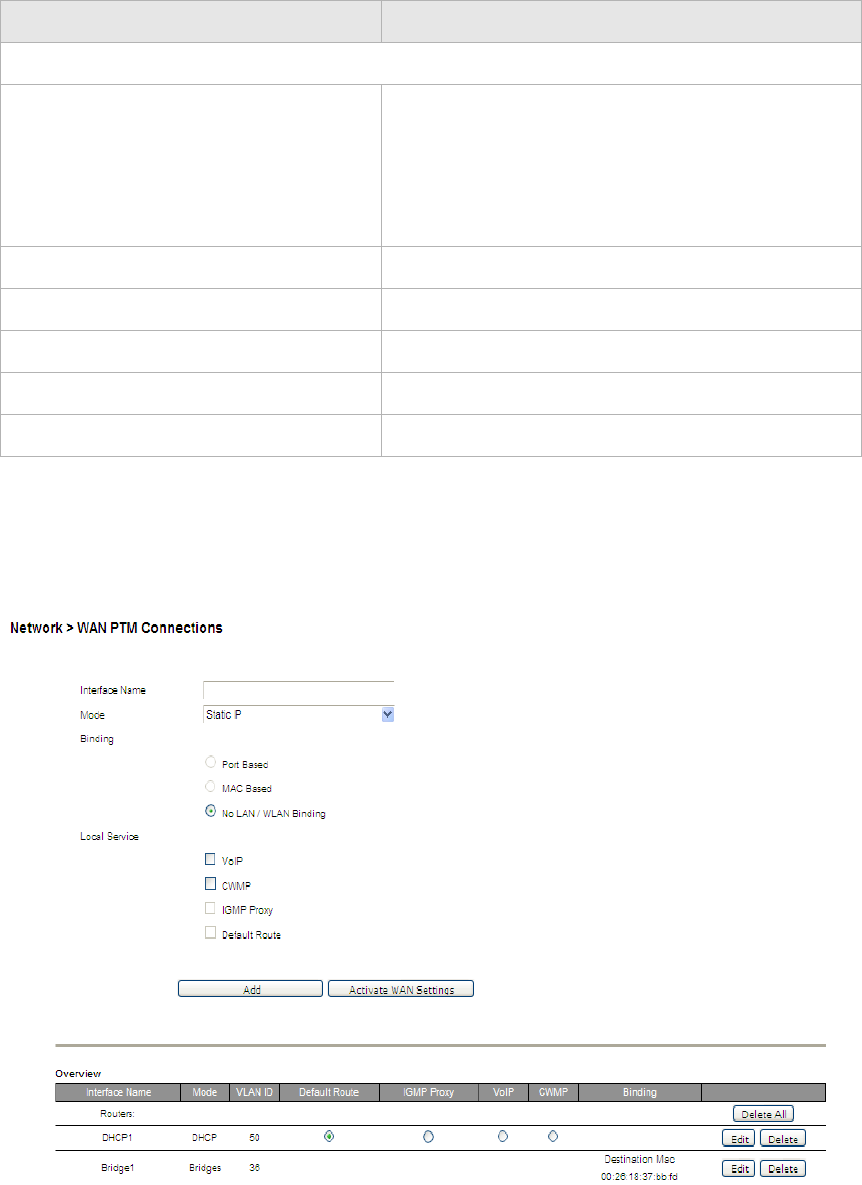
............................................................................................................................................................................................................................................................
WAN PT M ConnectionsNetwork
5-22 3EQ-10280-AAAA-TCZZA
Edition 01 February 2011
............................................................................................................................................................................................................................................................
After the second connection is set, you are returned to the WAN PTM Connections
window; see Figure 5-13. The two new connections, default and bridged, appear in the
Overview table.
Figure 5-13 WAN PTM Connections window with MAC based binding
You can only choose Bridge mode with MAC based binding and you can select Static IP,
DHCP, or PPPoE with No LAN/WLAN Binding for CWMP and VoIP.
WAN
VLAN Select Untagged if VLAN tagging is not to be
used for this WAN connection.
Select Always use ID if VLAN tagging is to be
used and enter the VLAN ID number (between 0
and 4094).
CoS Remarking Enter the CoS remarking number.
IP Address Enter the IP address provided by your ISP.
NetMask Enter the subnet mask provided by your ISP.
Next Click to proceed to the next step.
Back Click to return to the previous page.
Fields Description
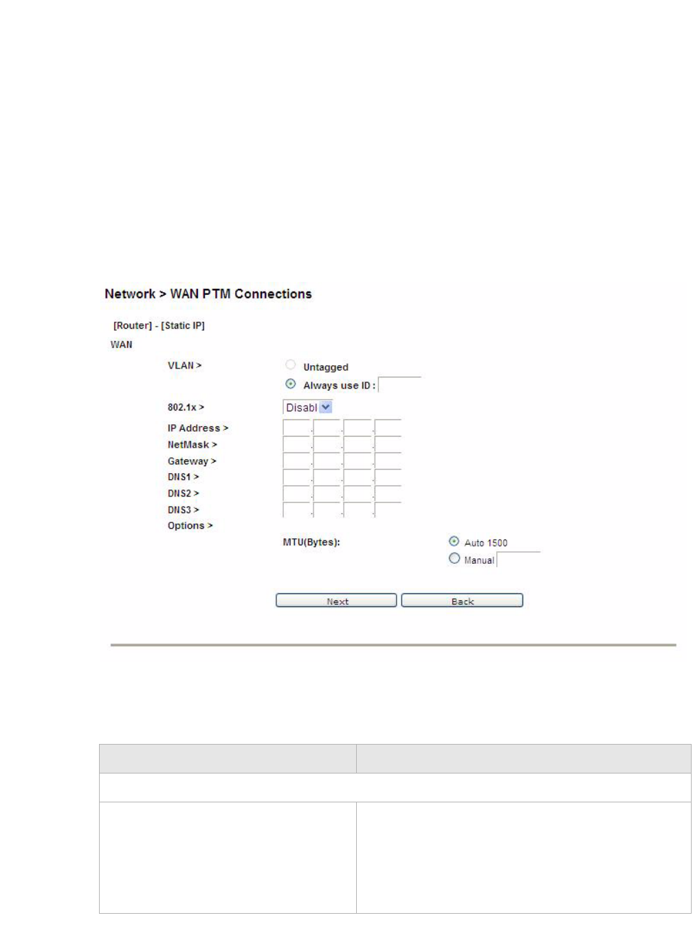
NetworkWAN PTM Connections
............................................................................................................................................................................................................................................................
3EQ-10280-AAAA-TCZZA
Edition 01 February 2011 5-23
............................................................................................................................................................................................................................................................
No LAN/WLAN binding
No LAN/WLAN binding enables you to configure your connection with local service
CWMP and VoIP. In order to avoid other connections using CWMP and VoIP, No
LAN/WLAN Binding is specifically for CWMP and VoIP to build an independent
connection.
Select the No LAN/WLAN Binding radio button for the binding method and then click Add
to enter the next configuration page.
Static IP
If you select Static IP as the mode and click Add, the Static IP window with No
LAN/WLAN Binding opens; see Figure 5-14.
Figure 5-14 Static IP window with No LAN/WLAN Binding
Table 5-11 describes the fields of Static IP window with No LAN/WLAN Binding.
Table 5-11 Field descriptions
Field Description
WAN
VLAN Select Untagged if VLAN tagging is not to be used
for this WAN connection.
Select Always use ID if VLAN tagging is to be
used and enter the VLAN ID number (between 0 to
4094).
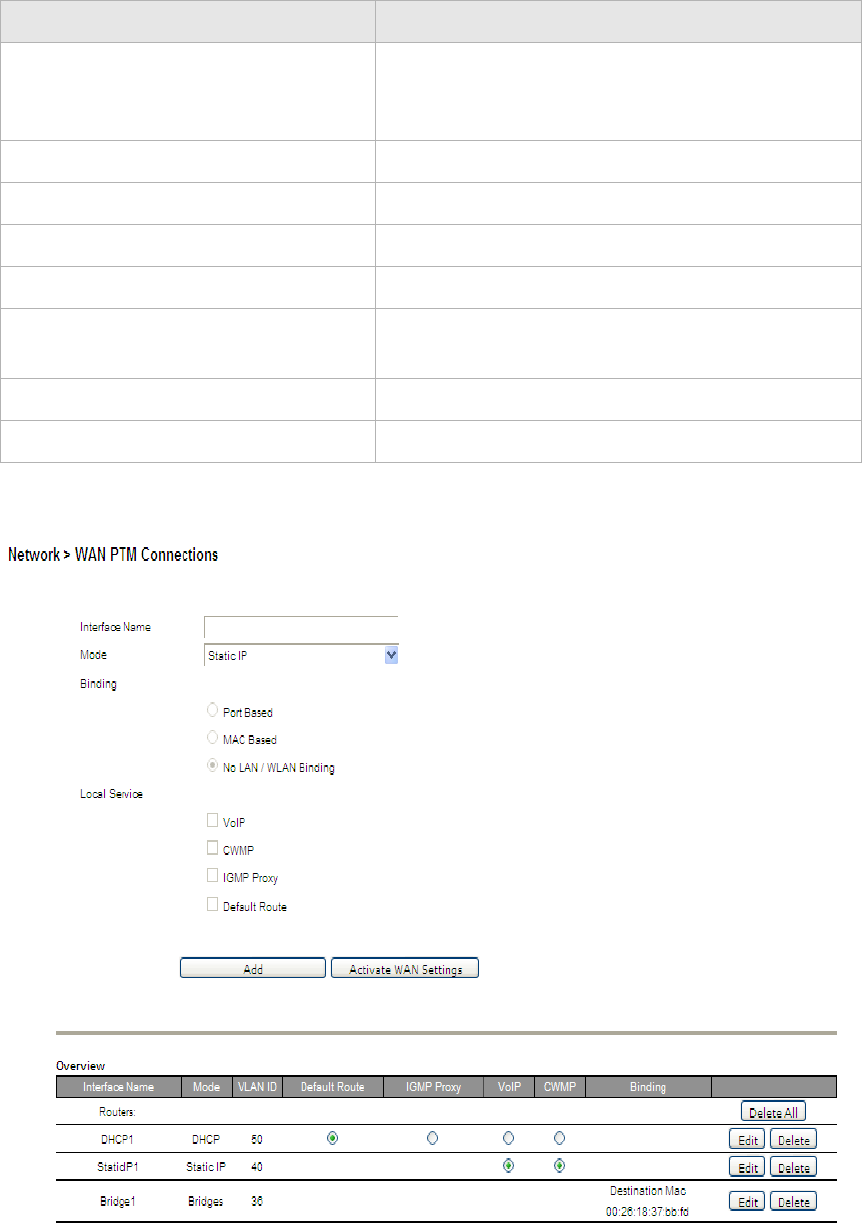
............................................................................................................................................................................................................................................................
WAN PT M ConnectionsNetwork
5-24 3EQ-10280-AAAA-TCZZA
Edition 01 February 2011
............................................................................................................................................................................................................................................................
Figure 5-15 WAN PTM Connections window with Static IP No LAN/WAN CWMP
connection created
802.1x Select Enable to use 802.1x or select Disable to
turn off 802.1x. Please consult your ISP for more
information.
IP Address Enter the IP address provided by your ISP.
NetMask Enter the subnet mask provided by your ISP.
Gateway Enter the gateway IP address provided by your ISP.
DNS1 to 3 Enter the DNS IP address (these are optional).
MTU(Bytes) Select Auto to set the MTU to the default (1500) or
select Manual and enter a value in bytes.
Next Click to proceed to the QoS Defaults window.
Back Click to return to the previous window.
Field Description
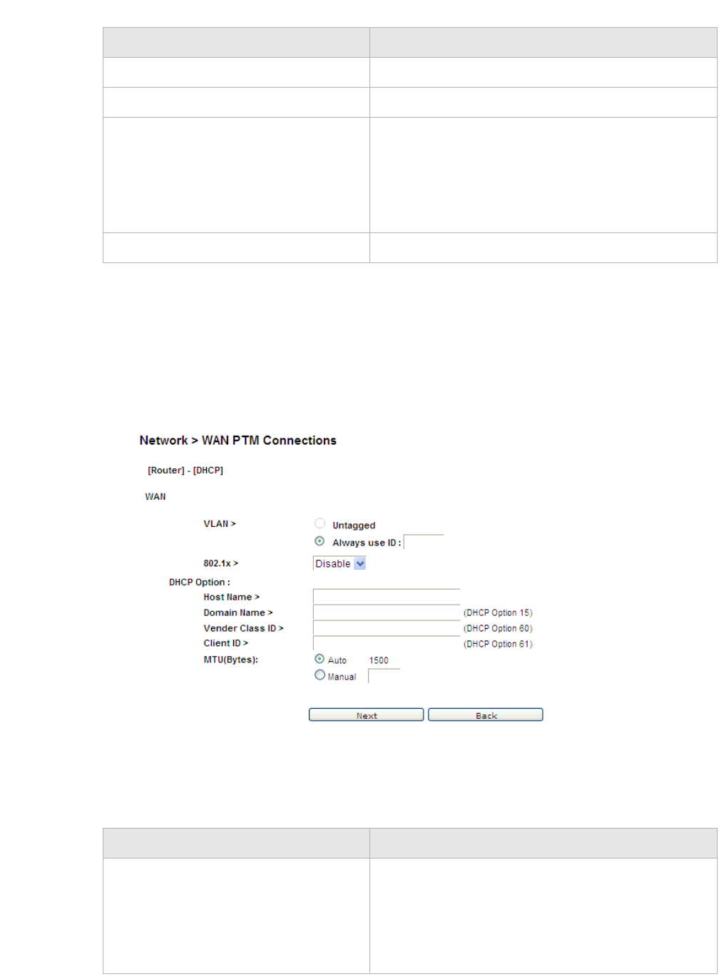
NetworkWAN PTM Connections
............................................................................................................................................................................................................................................................
3EQ-10280-AAAA-TCZZA
Edition 01 February 2011 5-25
............................................................................................................................................................................................................................................................
Table 5-12 Field descriptions
DHCP
If you select DHCP as the mode and click Add, the DHCP window with No LAN/WLAN
Binding opens; see Figure 5-16.
Figure 5-16 DHCP window with No LAN/WLAN Binding
Table 5-13 describes the fields of DHCP window with No LAN/WLAN Binding.
Table 5-13 Field descriptions
Field Description
Activate WAN Settings Click to activate the connection.
Delete All Click to delete all the connections.
Edit Click to modify the settings of the connection.
After changing the connection settings, press
Activate WAN Settings to activate the connection.
This button will be only visible if you made changes
to the settings or added a new connection.
Delete Click to delete the connection.
Field Description
VLAN Select Untagged if VLAN tagging is not to be used
for this WAN connection.
Select Always use ID if VLAN tagging is to be
used and enter the VLAN ID number (between 0 and
4094).

............................................................................................................................................................................................................................................................
WAN PT M ConnectionsNetwork
5-26 3EQ-10280-AAAA-TCZZA
Edition 01 February 2011
............................................................................................................................................................................................................................................................
PPPoE
If you select PPPoE as the mode and click Add, the PPPoE window with No LAN/WLAN
Binding opens; see Figure 5-17.
802.1x Select Enable to use 802.1x or select Disable to
turn off 802.1x. Please consult your ISP for more
information.
Host Name Enter the host name provided by your ISP. Please
consult with your ISP for more information.
Domain Name Enter the domain name provided by your ISP. Please
consult with your ISP for more information.
Vender Class ID If you are required, set the vender class ID to obtain
its lease from the DHCP server. Please consult with
your ISP for more information.
Client ID If you are required, set the client ID to obtain its
lease from the DHCP server. Please consult with
your ISP for more information.
MTU(Bytes) Select Auto to set the MTU to the default (1500) or
select Manual and enter a value in bytes.
Next Click to go to the QoS Defaults window.
Back Click to return to the previous window.
Field Description
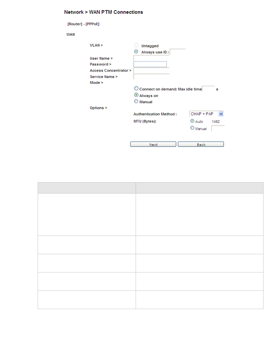
NetworkWAN PTM Connections
............................................................................................................................................................................................................................................................
3EQ-10280-AAAA-TCZZA
Edition 01 February 2011 5-27
............................................................................................................................................................................................................................................................
Figure 5-17 PPPoE window with No LAN/WLAN Binding
Table 5-14 describes the fields of PPPoE window with No LAN/WLAN Binding.
Table 5-14 Field descriptions
Field Description
VLAN Select Untagged if VLAN tagging is not to be used
for this WAN connection.
Select Always use ID if VLAN tagging is to be
used and enter the VLAN ID number (between 0 to
4094).
User Name Enter the username for the PPPoE connection.
Please consult with your ISP for more information.
Password Enter the password for the PPPoE connection.
Please consult with your ISP for more information.
Access Concentrator The access concentrator is optional. Please consult
with your ISP for more information.
Service Name The service name is optional. Please consult with
your ISP for more information.

............................................................................................................................................................................................................................................................
WAN PT M ConnectionsNetwork
5-28 3EQ-10280-AAAA-TCZZA
Edition 01 February 2011
............................................................................................................................................................................................................................................................
QoS Defaults
The QoS Defaults window enables you to configure the default QoS policy for each WAN
connection, see Figure 5-18.
Mode Select the mode:
•Select Connect on demand to allow the
gateway to connect to the Internet only when
you are trying to access it. Enter a Max idle
time. If there are no activities in the specified
time period, the CellPipe 7130 RG will
disconnect the connection.
•Select Always on to set the CellPipe 7130 RG
to always connect to the Internet.
•Select Manual and then click Connect to
manually connect the CellPipe 7130 RG to the
Internet. Click Disconnect to disconnect the
connection.
Authentication Method Select the authentication mode:
•CHAP + PAP
•Only MS-CHAP
•Only CHAP
•Only PAP
This is optional. Please consult with your ISP for
more information.
MTU (Bytes) Select Auto to set the MTU to the default (1492) or
select Manual and enter a value in bytes.
Next Click to go to the QoS Defaults window.
Back Click to return to the previous window.
Field Description
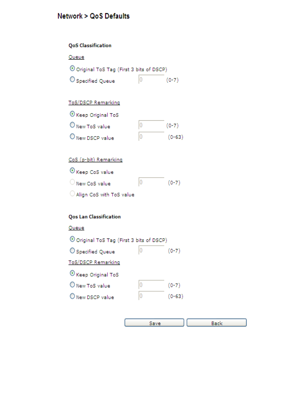
NetworkWAN PTM Connections
............................................................................................................................................................................................................................................................
3EQ-10280-AAAA-TCZZA
Edition 01 February 2011 5-29
............................................................................................................................................................................................................................................................
Figure 5-18 QoS Defaults window

............................................................................................................................................................................................................................................................
WAN PT M ConnectionsNetwork
5-30 3EQ-10280-AAAA-TCZZA
Edition 01 February 2011
............................................................................................................................................................................................................................................................
Table 5-15 describes the fields of the QoS Defaults window.
Table 5-15 Field descriptions
Field Description
QoS Classification
Queue
Original ToS Tag (First 3 bits of
DSCP)
Select Original ToS Tag to assign the queue according
to the ToS value of the packet.
Specified Queue Select Specified Queue and enter a queue number (0
to 7) to which the network traffic will be assigned.
Note: When Specified Queue is chosen, you cannot
choose Align CoS with ToS Value.
ToS/DSCP Remarking
Keep Original ToS Select Keep Original ToS to retain the original ToS
value.
New ToS Value Select New Tos Value and enter a queue number (0 to
7) to assign to the network traffic.
New DSCP Value Select New DSCP Value and enter a DSCP value (0 to
63).
CoS (p-bit) Remarking
Keep CoS Value Select Keep CoS Value to retain the original CoS value.
New CoS Value Select New CoS Value to assign CoS for network
traffic.
Align CoS with ToS Value Select to align CoS with ToS value.
Note: This field can only be set if you keep Original
To S Ta g in queue setting.
QoS LAN Classification
Queue
Original ToS Tag (First 3 bits of
DSCP)
Select Original ToS Tag to assign the queue according
to the ToS value of the packet.
Specified Queue Select Specified Queue and enter a queue number (0
to 7) to which the network traffic will be assigned.
Note: When Specified Queue is chosen, you cannot
choose Align CoS with ToS Value.
ToS/DSCP Remarking
Keep Original ToS Select Keep Original ToS to retain the original ToS
value.

Network
............................................................................................................................................................................................................................................................
3EQ-10280-AAAA-TCZZA
Edition 01 February 2011 5-31
............................................................................................................................................................................................................................................................
New ToS Value Select New Tos Value and enter a queue number (0 to
7) to assign to the network traffic.
New DSCP Value Select New DSCP Value and enter a DSCP value (0 to
63).
Save Click to save your changes.
Back Click to return to the previous window.
Field Description
............................................................................................................................................................................................................................................................
Network
5-32 3EQ-10280-AAAA-TCZZA
Edition 01 February 2011
............................................................................................................................................................................................................................................................

6-1
3EQ-10280-AAAA-TCZZA
Edition 01 February 2011
............................................................................................................................................................................................................................................................
6 WiFi setup
Overview
Purpose
This chapter explains how to configure the WiFi settings for the CellPipe 7130 RG.
Click WiFi Setup in the main menu to open the WiFi Setup menu.
Contents
This chapter covers the following topics:
WiFi Settings
The WiFi Settings window enables you to configure the common wireless settings.
Click on WiFi Settings in the WiFi Setup menu to access the WiFi Settings window; see
Figure 6-1.
WiFi Settings 6-1
WiFi Security 6-4
WiFi Access Filter 6-6
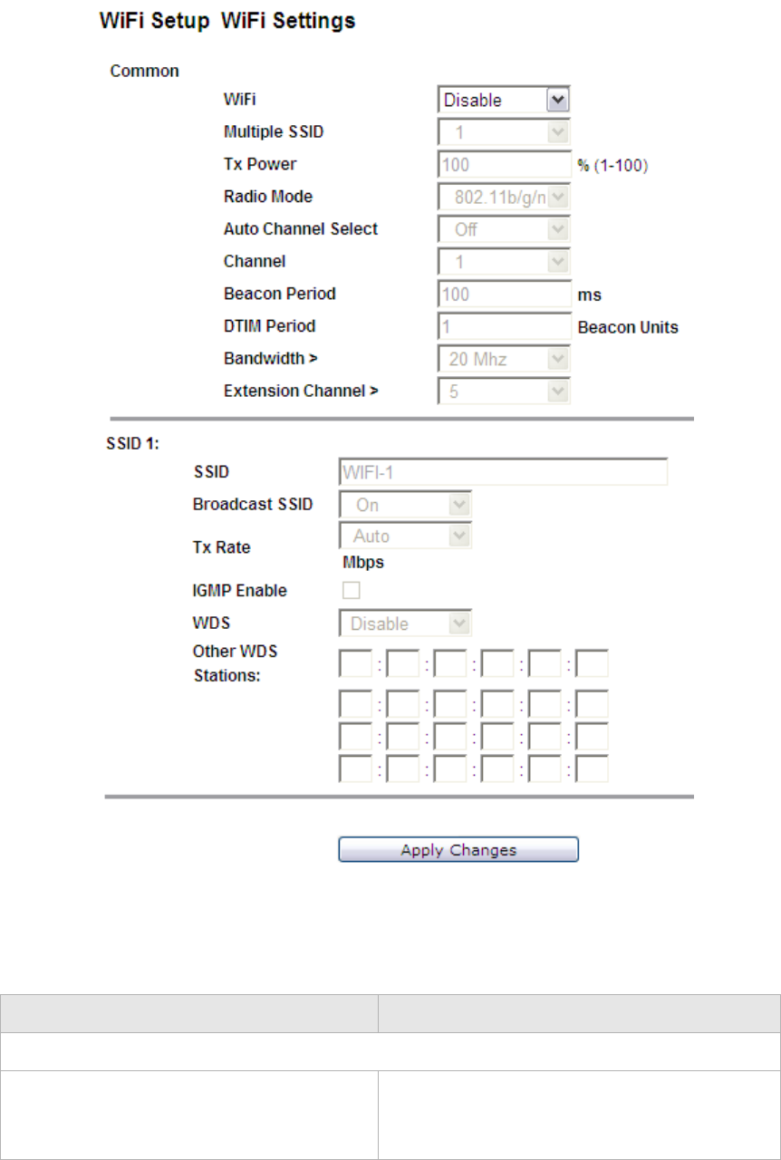
............................................................................................................................................................................................................................................................
WiFi SettingsWiFi setup
6-2 3EQ-10280-AAAA-TCZZA
Edition 01 February 2011
............................................................................................................................................................................................................................................................
Figure 6-1 WiFi Settings window
Table 6-1 describes the fields of the WiFi Settings window.
Table 6-1 Field descriptions
Field Description
Common
WiFi Select Enable to turn on wireless and configure
the wireless settings. Select Disable to turn off
wireless.

WiFi setupWiFi Settings
............................................................................................................................................................................................................................................................
3EQ-10280-AAAA-TCZZA
Edition 01 February 2011 6-3
............................................................................................................................................................................................................................................................
Multiple SSID Select the number of SSIDs:
•1
•2
•4
Tx Power Enter a value between 1 and 100 to control the
transmitting signal strength.
Radio Mode Select the wireless mode:
•802.11b/g
•802.11g/n
•802.11b/g/n
•802.11b
•802.11g
•802.11n
Auto Channel Select Select On to let the wireless access point
automatically select a channel with the least
interference. Select Off to configure manually.
Select Now to set the channel automatically
one time.
Channel If Auto Channel Select is off, you can manually
select a channel for the wireless access point.
The default is 1.
Beacon Period Enter a beacon period in milliseconds to
determine the frequency of the beacon to keep
the network synchronized. This is optional.
DTIM Period Enter a value to set the delivery traffic
indication message. The DTIM field is a
countdown field informing clients of the next
window for listening to broadcast and multicast
messages.
Bandwidth Select to enable channel bonding (20/40Mhz)
or disable channel bonding . If channel bonding
is selected, please also select which extension
channel is been used. Note: Not all wireless
clients support this.
Extension Channel An extension channel is a secondary channel
used to bond with the primary channel to
increase the performance.
Field Description

............................................................................................................................................................................................................................................................
WiFi SecurityWiFi setup
6-4 3EQ-10280-AAAA-TCZZA
Edition 01 February 2011
............................................................................................................................................................................................................................................................
WiFi Security
WiFi security enables you to configure the WEP, WPA, or WPA2 security settings.
Select WiFi Security in the WiFi Setup menu to access the WiFi Security window; see
Figure 6-2.
SSID 1 to 4
SSID Enter an SSID name (maximum of 32
characters). The SSID is an alphanumeric name
shared by all the devices on the wireless
network. It must be unique.
Broadcast SSID Select On to broadcast the SSID or select Off to
hide the SSID.
TxRate Select Auto to automatically determine the
transmission rate or manually select a
transmission rate (maximum 54Mb/s).
IGMP Enable Enable to use IGMP or disable to turn off
IGMP.
WDS Select Enable to use WDS or select Disable to
turn off WDS.
Note: If you enable WDS, ensure that all
other WDS APs are enabled, configured with
the same channel, SSID, and encryption keys,
and that each AP has a different LAN port IP
address.
Other WDS Station Enter the wireless MAC addresses of other
wireless APs or routers that are in the same
WDS.
Apply Changes Click to save your changes.
Field Description
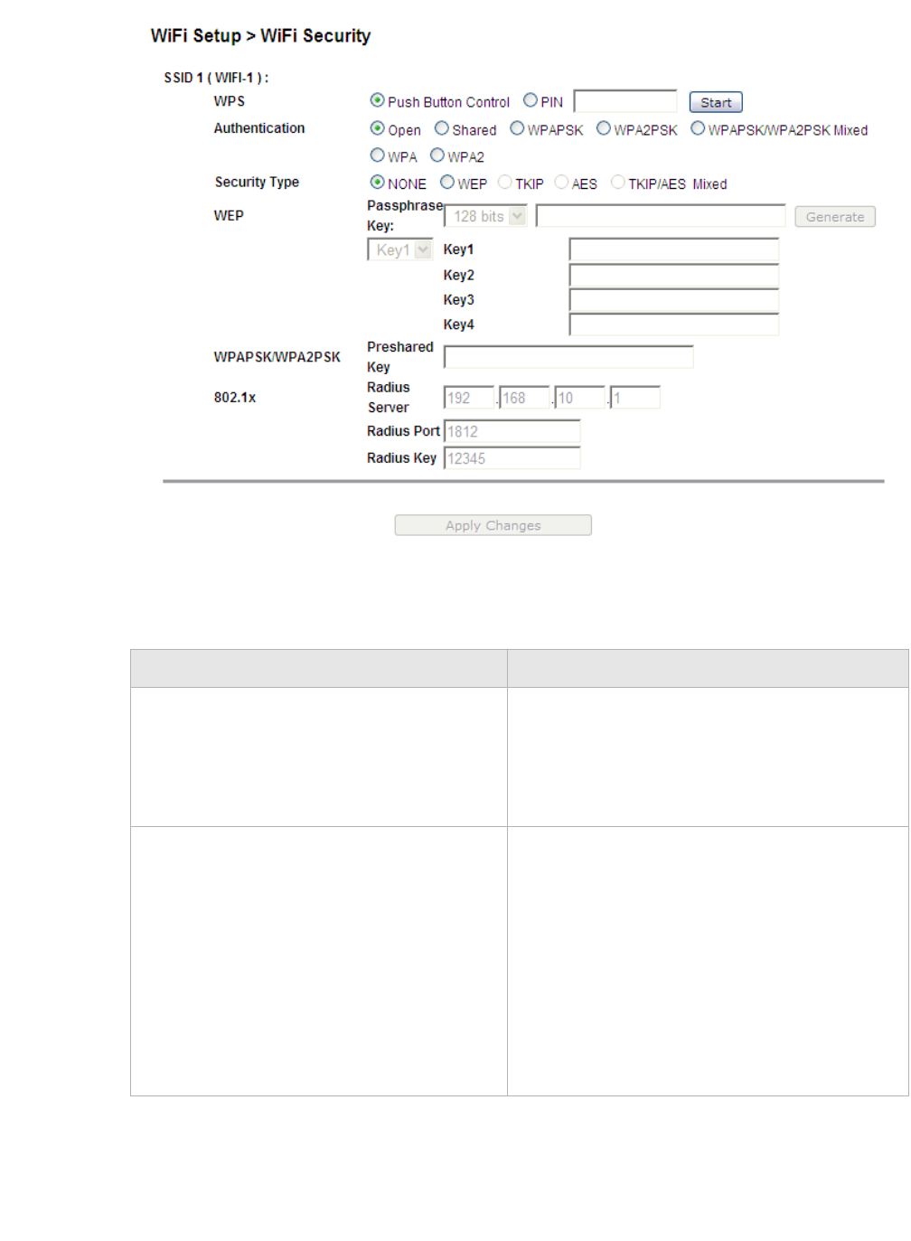
WiFi setupWiFi Security
............................................................................................................................................................................................................................................................
3EQ-10280-AAAA-TCZZA
Edition 01 February 2011 6-5
............................................................................................................................................................................................................................................................
Figure 6-2 WiFi Security window
Table 6-2 describes the fields of the WiFi Security window.
Table 6-2 Field descriptions
Field Description
WPS Enable Push Button Control (the WPS push
button is located on the front of the CellPipe
7130 RG) or enable PIN and enter your PIN
number and click Start. The PIN number is
located in the WiFi utility of your computer.
Authentication Select one of the following encryption methods
for the wireless network:
•Open
•Shared
•WPAPSK
•WPA2PSK
•WPAPSK/WPA2PSK Mixed
•WPA
•WPA2

............................................................................................................................................................................................................................................................
WiFi Access FilterWiFi setup
6-6 3EQ-10280-AAAA-TCZZA
Edition 01 February 2011
............................................................................................................................................................................................................................................................
WiFi Access Filter
The WiFi Access Filter window enables you to block or permit access for wireless clients
by MAC address.
Select WiFi Access Filter in the WiFi Setup menu to access the WiFi Access Filter
window; see Figure 6-3.
Security Type Select one of the following for the security
type:
•NONE
•WEP
•TKIP
•AES
•TKIP/AES Mixed
WEP
Passphrase Key Select a level of encryption (64 bits or 128
bits) and enter a passphrase key consisting of 8
to 63 alphanumeric characters and then click
Generate.
Key1 to 4 Select Key1 to Key4 and enter a WEP key in
the respective field. The WEP key must:
•contain letters from A to F and numbers
from 0 to 9
•contain 10 characters for 64 bit and 26
characters for 128 bit encryption
WPAPSK/WPA2PSK
Preshared Key Enter a preshared key consisting of 8 to 63
alphanumeric characters.
802.1x
Radius Server Enter the IP address of the RADIUS server.
Radius Port Enter the port number of the RADIUS server.
Radius Key Enter the key of the RADIUS server.
Apply Changes Click to save your changes.
Field Description
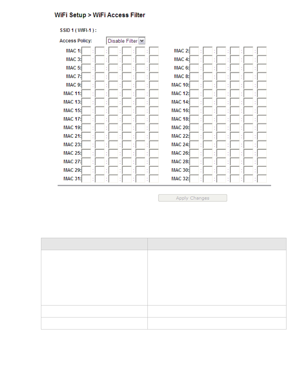
WiFi setupWiFi Access Filter
............................................................................................................................................................................................................................................................
3EQ-10280-AAAA-TCZZA
Edition 01 February 2011 6-7
............................................................................................................................................................................................................................................................
Figure 6-3 WiFi Access Filter window
Table 6-3 describes the fields of the WiFi Access Filter window.
Table 6-3 Field descriptions
Field Description
Access Policy Select an access policy:
•Disable Filter to turn off WiFi filtering.
•Allow to permit access from the specified MAC
address.
•Deny to deny access from the specified MAC
address.
MAC 1 to 32 Enter up to 32 MAC addresses to control access.
Apply Changes Click to save your changes.
............................................................................................................................................................................................................................................................
WiFi Access FilterWiFi setup
6-8 3EQ-10280-AAAA-TCZZA
Edition 01 February 2011
............................................................................................................................................................................................................................................................

7-1
3EQ-10280-AAAA-TCZZA
Edition 01 February 2011
............................................................................................................................................................................................................................................................
7Firewall setup
Overview
Purpose
This chapter explains how to configure the firewall for the CellPipe 7130 RG.
Click Firewall Setup in the main menu to open the Firewall Setup menu.
Contents
This chapter covers the following topics:
Port Forwarding
The Port Forwarding window enables you to control the incoming requests from the
Internet to pass through the port to your local computer.
Note: It is recommended that port forwarding be configured with the assistance of
your ISP.
Select Port Forwarding in the Firewall Setup menu to open the Port Forwarding
window; see Figure 7-1.
Port Forwarding 7-1
Demilitarized Zone 7-3
UPnP 7-4
Layer 2 Filter 7-5
Layer 3 Filter 7-7
NAT Passthrough 7-8
URL Blocking 7-9
Content Screening 7-10
Parental Control 7-11
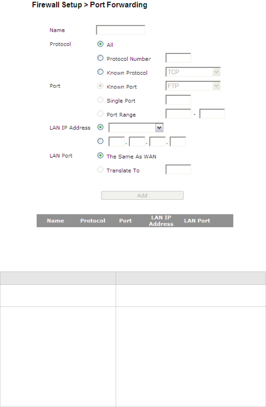
............................................................................................................................................................................................................................................................
Port ForwardingFirewall setup
7-2 3EQ-10280-AAAA-TCZZA
Edition 01 February 2011
............................................................................................................................................................................................................................................................
Figure 7-1 Port Forwarding window
Table 7-1 describes the fields of the Port Forwarding window.
Table 7-1 Field descriptions
Field Description
Name Enter a name for the application you are hosting on
your LAN computer; for example, Real Audio.
Protocol Select the type of IP protocol(s) used by this
application:
•ALL
•Protocol Number and then enter the protocol
number
•Known Protocol and then select a protocol:
•TCP
•UDP
•TCP/UDP
•ICMP

Firewall setupDemilitarized Zone
............................................................................................................................................................................................................................................................
3EQ-10280-AAAA-TCZZA
Edition 01 February 2011 7-3
............................................................................................................................................................................................................................................................
Demilitarized Zone
The Demilitarized Zone window enables you to configure a single computer on the local
side to be exposed to the Internet. All incoming packets will be forwarded to this
computer.
Note: Use the demilitarized zone setting only if the virtual server or port range
forwarding options do not provide the level of access required for certain applications.
It is recommended that you contact your ISP for assistance.
Select Demilitarized Zone in the Firewall Setup menu to access the Demilitarized Zone
window; see Figure 7-2.
Port Select or enter the TCP/UDP port for which the port
forwarding route must be applied.
•Known Port and then select a port:
•FTP
•TFTP
•TELNET
•SSH
•HTTP
•HTTPS
•SMTP
•POP3
•DNS
•IMAP
•Single Port and then enter the port number
•Port Range and then enter the port range
LAN IP Address Select the first radio button to choose a pre-
configured LAN host or select the second radio
button to enter an IP address manually.
LAN Port Select the first radio button to use the same port or
port range as the WAN or select the second radio
button and enter the LAN port manually.
Apply Changes Click to save your changes.
Field Description
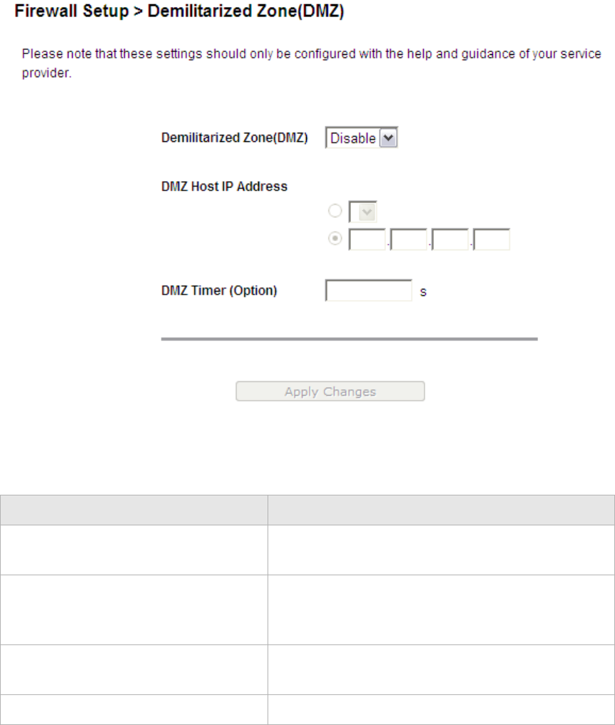
............................................................................................................................................................................................................................................................
UPnPFirewall setup
7-4 3EQ-10280-AAAA-TCZZA
Edition 01 February 2011
............................................................................................................................................................................................................................................................
Figure 7-2 Demilitarized Zone window
Table 7-2 describes the fields of the Demilitarized Zone window.
Table 7-2 Field descriptions
UPnP
UPnP is an open networking standard that allows peer-to-peer network connectivity
between devices. It enables software or devices, such as video game consoles, to function
properly using NAT.
Note: It is recommended that you contact your ISP for assistance.
Field Description
Demilitarized Zone(DMZ) Select Enable to turn on the demilitarized zone
function. Select Disable to turn it off.
DMZ Host IP Address Select the first radio button and choose a pre-
existing LAN host or select the second radio button
to enter an IP address manually.
DMZ Timer (Option) To improve security, specify the length of time (in
seconds) during which the DMZ is active.
Apply Changes Click to save your changes.
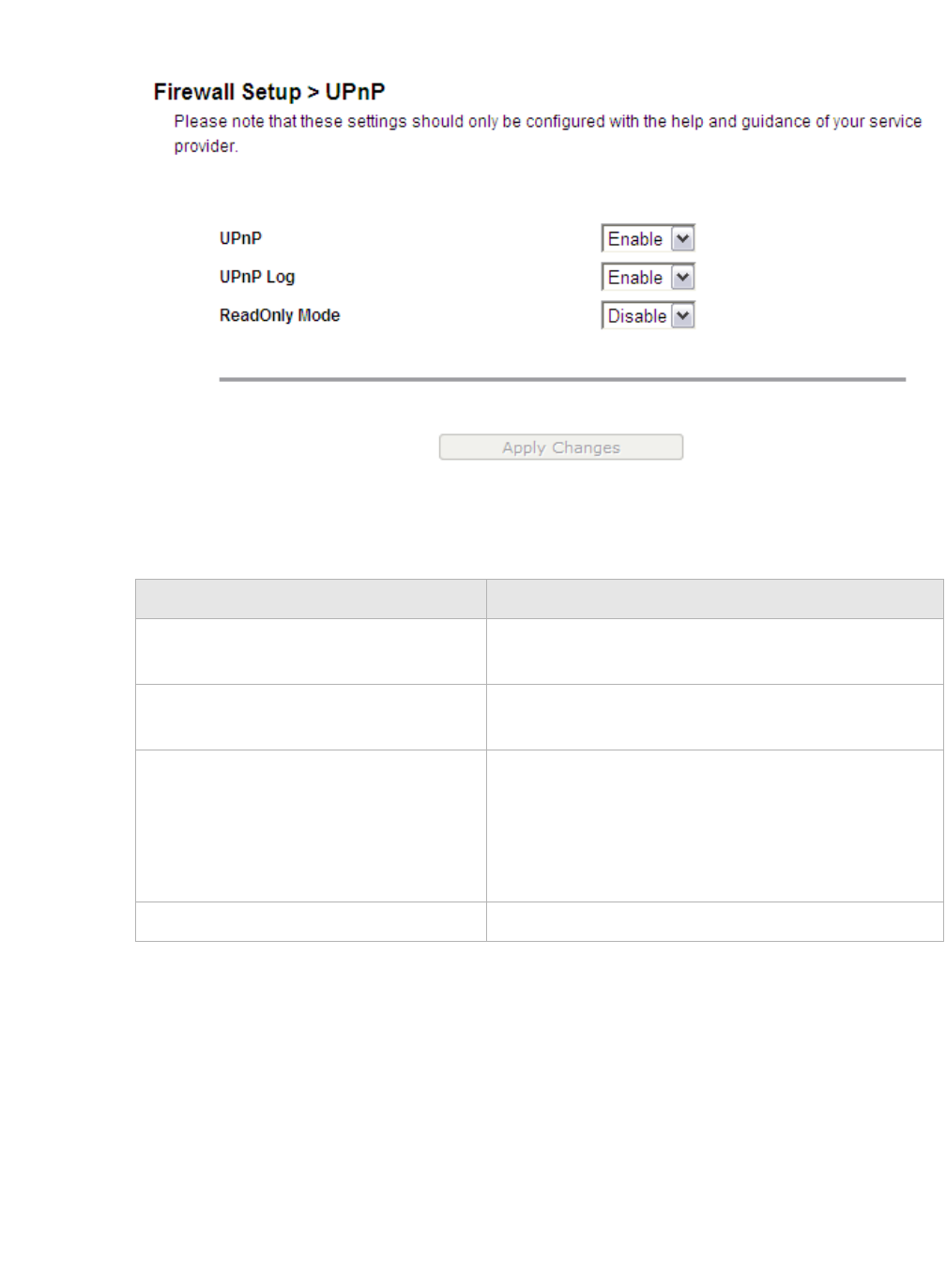
Firewall setupLayer 2 Filter
............................................................................................................................................................................................................................................................
3EQ-10280-AAAA-TCZZA
Edition 01 February 2011 7-5
............................................................................................................................................................................................................................................................
Select UPnP in the Firewall Setup menu to access the UPnP window; see Figure 7-3.
Figure 7-3 UPnP window
Table 7-3 describes the fields of the UPnP window.
Table 7-3 Field descriptions
Layer 2 Filter
Select Layer 2 Filter in the Firewall Setup menu to access the Layer 2 Filter window; see
Figure 7-4.
Field Description
UPnP Select Enable to turn on the UPnP function. Select
Disable to turn off the UPnP function.
UPnP Log Select Enable to turn on logging activities. Select
Disable to turn off the logging activities.
ReadOnly Mode Select Enable to turn on the read-only mode. Select
Disable to turn off the read-only mode.
Note: In read-only mode, users are unable to
change port forwarding settings or any other UPnP
enabled application settings.
Apply Changes Click to save your changes.
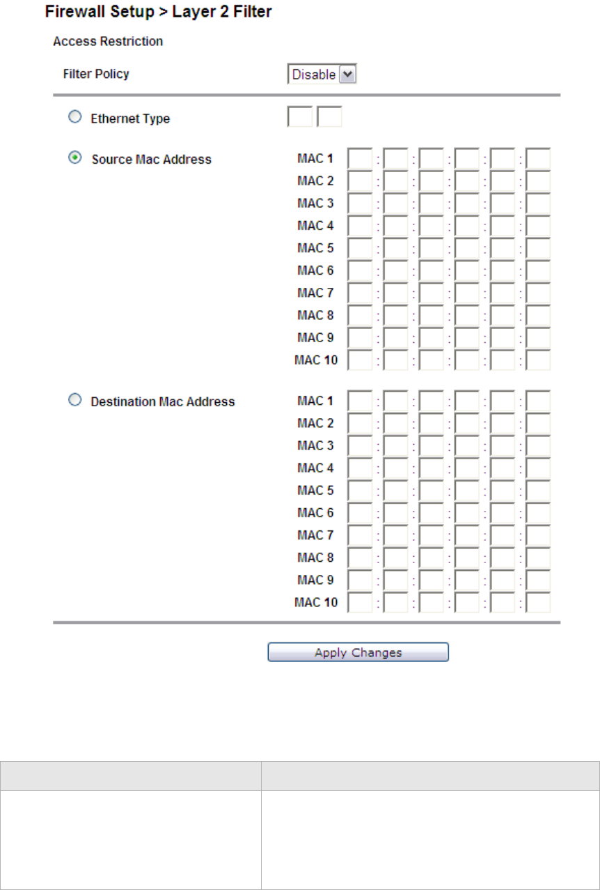
............................................................................................................................................................................................................................................................
Layer 2 FilterFirewall setup
7-6 3EQ-10280-AAAA-TCZZA
Edition 01 February 2011
............................................................................................................................................................................................................................................................
Figure 7-4 Layer 2 Filter window
Table 7-4 describes the fields of the Layer 2 Filter window.
Table 7-4 Field descriptions
Field Description
Filter Policy Select the policy for filters:
•Allow
•Deny
•Disable
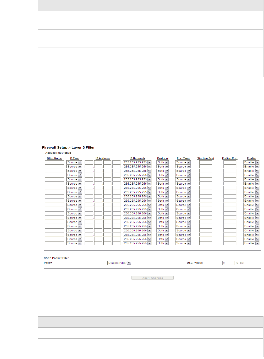
Firewall setupLayer 3 Filter
............................................................................................................................................................................................................................................................
3EQ-10280-AAAA-TCZZA
Edition 01 February 2011 7-7
............................................................................................................................................................................................................................................................
Layer 3 Filter
Select Layer 3 Filter in the Firewall Setup menu to access the Layer 3 Filter window; see
Figure 7-5.
Figure 7-5 Layer 3 Filter window
Table 7-5 describes the fields of the Layer 3 Filter window.
Table 7-5 Field descriptions
Ethernet Type Select to use Ethernet Type as the filtering algorithm
and enter the applicable Ethernet Type code.
Source Mac Address 1 to 10 Select and then enter the source MAC address of the
device.
Destination Mac Address 1 to 10 Select and then enter the destination MAC address
of the device.
Apply Changes Click to save your changes.
Field Description
Field Description
Filter Name Enter a name for the filtering rule.
IP Type Select Dest (destination) or Source depending on
the how the rule is going to be used.

............................................................................................................................................................................................................................................................
NAT PassthroughFirewall setup
7-8 3EQ-10280-AAAA-TCZZA
Edition 01 February 2011
............................................................................................................................................................................................................................................................
NAT Passthrough
The NAT Passthrough window allows you to enable or disable specific protocols from
passing through the gateway.
Note: This should only be configured with the help of your ISP.
Select NAT Passthrough in the Firewall Setup menu to access the NAT Passthrough
window; see Figure 7-6.
IP Address Enter the IP address of the host that you are
blocking.
IP Netmask Select the subnet mask of the host that you are
blocking.
Protocol Select the type of protocol(s) used by the
application:
•TCP
•UDP
•Both
Port Type Select Dest (destination) or Source depending on
the type of application.
Starting Port Enter the start port of the ports used by the
application.
Ending Port Enter the end port of the ports used by the
application.
Enable Select Enable to apply the filter rule or Disable to
turn off the filter rule.
DSCP Packet Filter Policy Select Disable to disable the DSCP policy. Select
Deny to deny packets that are accessing the Internet
with the specified DSCP value in the IP header or
select Allow to allow packets that are accessing the
Internet with the specified DSCP value in the IP
header.
DSCP Value Enter a DSCP value between 0 and 63.
Apply Changes Click to save your changes.
Field Description
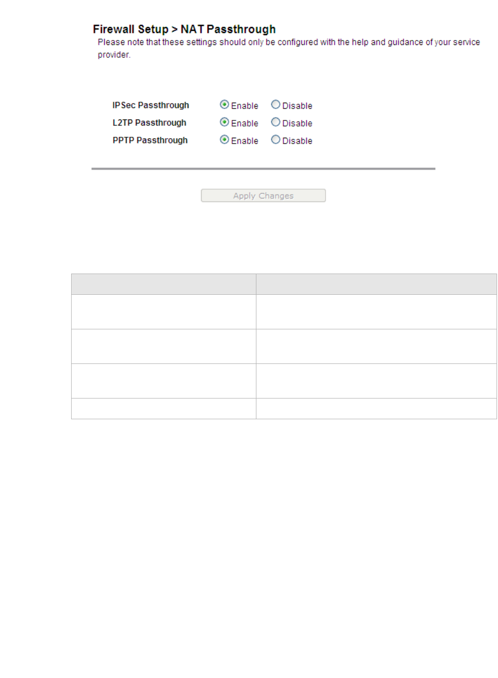
Firewall setupURL Blocking
............................................................................................................................................................................................................................................................
3EQ-10280-AAAA-TCZZA
Edition 01 February 2011 7-9
............................................................................................................................................................................................................................................................
Figure 7-6 NAT Passthrough window
Table 7-6 describes the fields of the NAT Passthrough window.
Table 7-6 Field descriptions
URL Blocking
The URL Blocking window enables you to block requests from your local computer to
access specific websites.
Select URL Blocking in the Firewall Setup menu to access the URL Blocking window;
see Figure 7-7.
Field Description
IPSec Passthrough Select Enable to allow IPSec passthrough. Select
Disable to turn off the IPSec passthrough.
L2TP Passthrough Select Enable to allow L2TP passthrough. Select
Disable to turn off L2TP passthrough.
PPTP Passthrough Select Enable to allow PPTP passthrough. Select
Disable to turn off PPTP passthrough.
Apply Changes Click to save your changes.
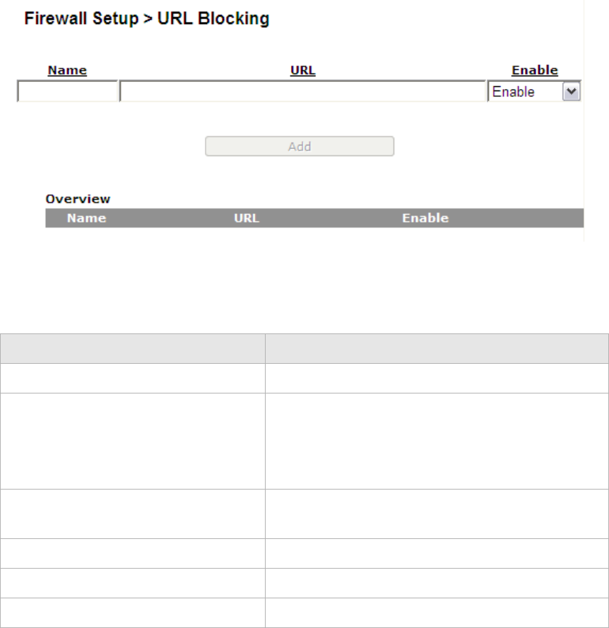
............................................................................................................................................................................................................................................................
Content ScreeningFirewall setup
7-10 3EQ-10280-AAAA-TCZZA
Edition 01 February 2011
............................................................................................................................................................................................................................................................
Figure 7-7 URL Blocking window
Table 7-7 describes the fields of the URL Blocking window.
Table 7-7 Field descriptions
Content Screening
The Content Screening window enables you to configure keywords to screen website
content. If the keywords appear in the website content and content screening is enabled,
the firewall will block the user from accessing the website.
Note: Compressed and secured pages are not supported.
Select Content Screening in the Firewall Setup menu to access the Content Screening
window; see Figure 7-8.
Field Description
Name Enter a name for the URL filter.
URL Enter a URL or a prefix keyword of the URL you are
blocking.
Note: If the keyword is too general, you might
inadvertently block other websites.
Enable Select Enable to apply the URL filter. Select
Disable to turn off the URL filter.
Add Click to add the URL blocking rule.
Edit Click to edit the URL blocking rule.
Delete Click to delete the URL blocking rule.
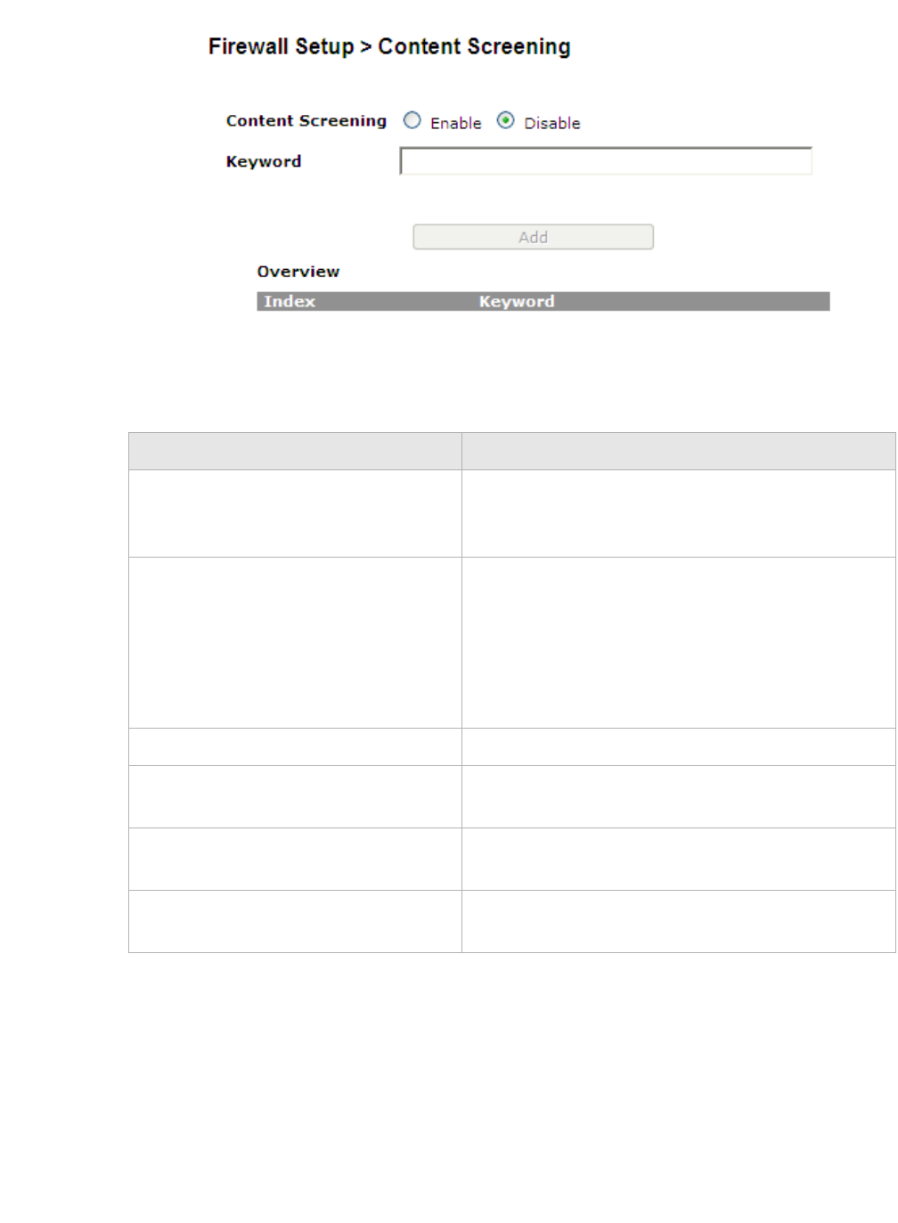
Firewall setupParental Control
............................................................................................................................................................................................................................................................
3EQ-10280-AAAA-TCZZA
Edition 01 February 2011 7-11
............................................................................................................................................................................................................................................................
Figure 7-8 Content Screening window
Table 7-8 describes the fields of the Content Screening window.
Table 7-8 Field descriptions
Parental Control
The Parental Control window enables you to set Internet connection limits on your
computer based on the time and day of the week.
Select Parental Control in the Firewall Setup menu to access the Parental Control
window; see Figure 7-9.
Field Description
Content Screening Select Enable to apply content screening and block
websites that have keywords in their contents. Select
Disable to disable content screening.
Keyword Enter a keyword to be blocked. Enter only one
keyword. If you want to screen multiple keywords,
add them as separate rules. The maximum number
of keywords allowed is 254.
Note: If the keyword is too general, you might
inadvertently block other websites.
Index The index of rule. The index is created by system.
Add Click to add the keyword to the content screening
rules.
Edit Click to edit the keyword to the content screening
rules.
Delete Click to delete the keyword to the content screening
rules.
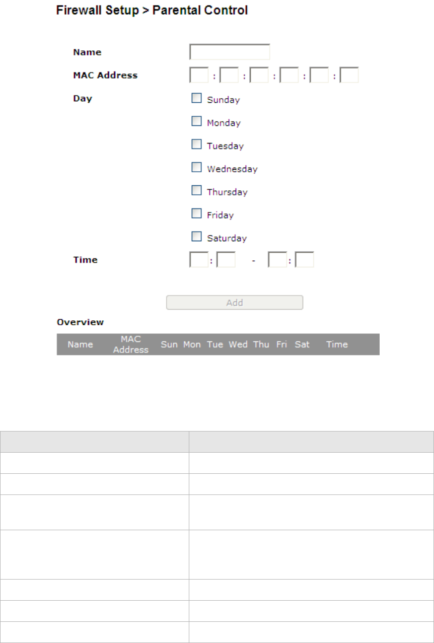
............................................................................................................................................................................................................................................................
Parental ControlFirewall setup
7-12 3EQ-10280-AAAA-TCZZA
Edition 01 February 2011
............................................................................................................................................................................................................................................................
Figure 7-9 Parental Control window
Table 7-9 describes the fields of the Parental Control window.
Table 7-9 Field descriptions
Field Description
Name Enter a name for the rule.
MAC Address Enter the MAC address of the LAN device.
Day Enable the day(s) of the week you want to limit the
Internet connection of the client. This is optional.
Time Enter a time period (in hours and minutes) that you
want to limit the Internet connection of the client.
This is optional.
Add Click to add the rule.
Edit Click to edit the rule.
Delete Click to delete the rule.

8-1
3EQ-10280-AAAA-TCZZA
Edition 01 February 2011
............................................................................................................................................................................................................................................................
8 Advanced setup
Overview
This chapter explains how to configure the advanced settings of the CellPipe 7130 RG
such as the route settings, DNS settings, dynamic DNS, system log, IGMP
proxy/snooping, and 802.1x.
Click Advanced Setup in the main menu to open the Advanced Setup menu.
Contents
This chapter covers the following topics:
Route Settings
The Route Settings window enables you to configure static and dynamic routes for routing
packets from one network to another network.
Select Route Settings in the Advanced Setup menu to access the Route Settings window;
see Figure 8-1.
Route Settings 8-1
DNS Settings 8-3
Dynamic DNS 8-4
System Log 8-5
IGMP Proxy/Snooping 8-6
802.1x Config 8-7
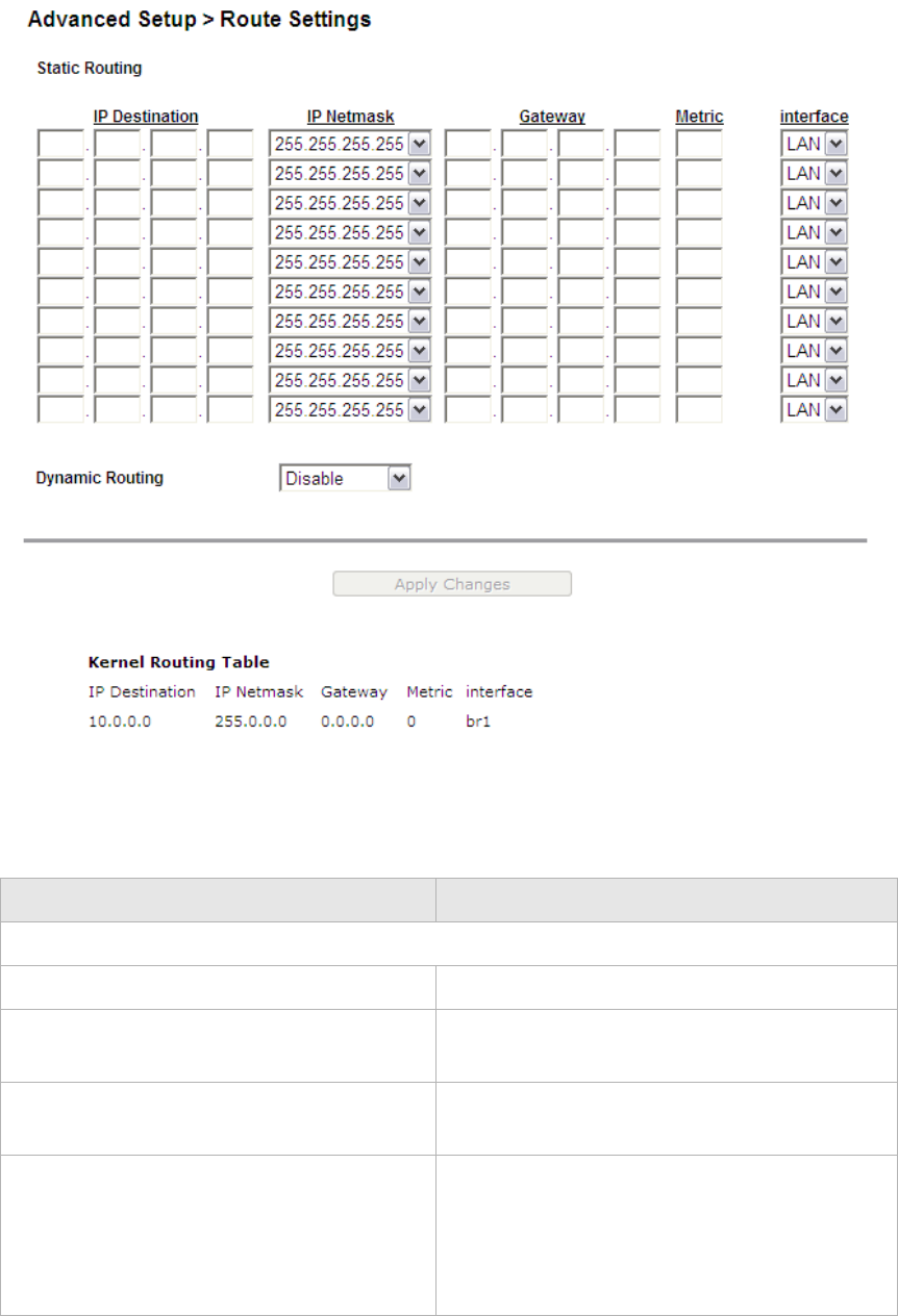
............................................................................................................................................................................................................................................................
Route SettingsAdvanced setup
8-2 3EQ-10280-AAAA-TCZZA
Edition 01 February 2011
............................................................................................................................................................................................................................................................
Figure 8-1 Route Settings window
Table 8-1 describes the fields of the Route Settings window.
Table 8-1 Field descriptions
Field Description
Static Routing
IP Destination Enter the IP address of the destination network.
IP Netmask Select the subnet mask of the destination
network.
Gateway Enter the IP address of the gateway for the
destination network.
Metric In order to determine the best route, a value is
used to specify the cost of the route (the metric
value). Enter the metric value in the metric
field. IP routing uses hop count as measurement
of the metric.
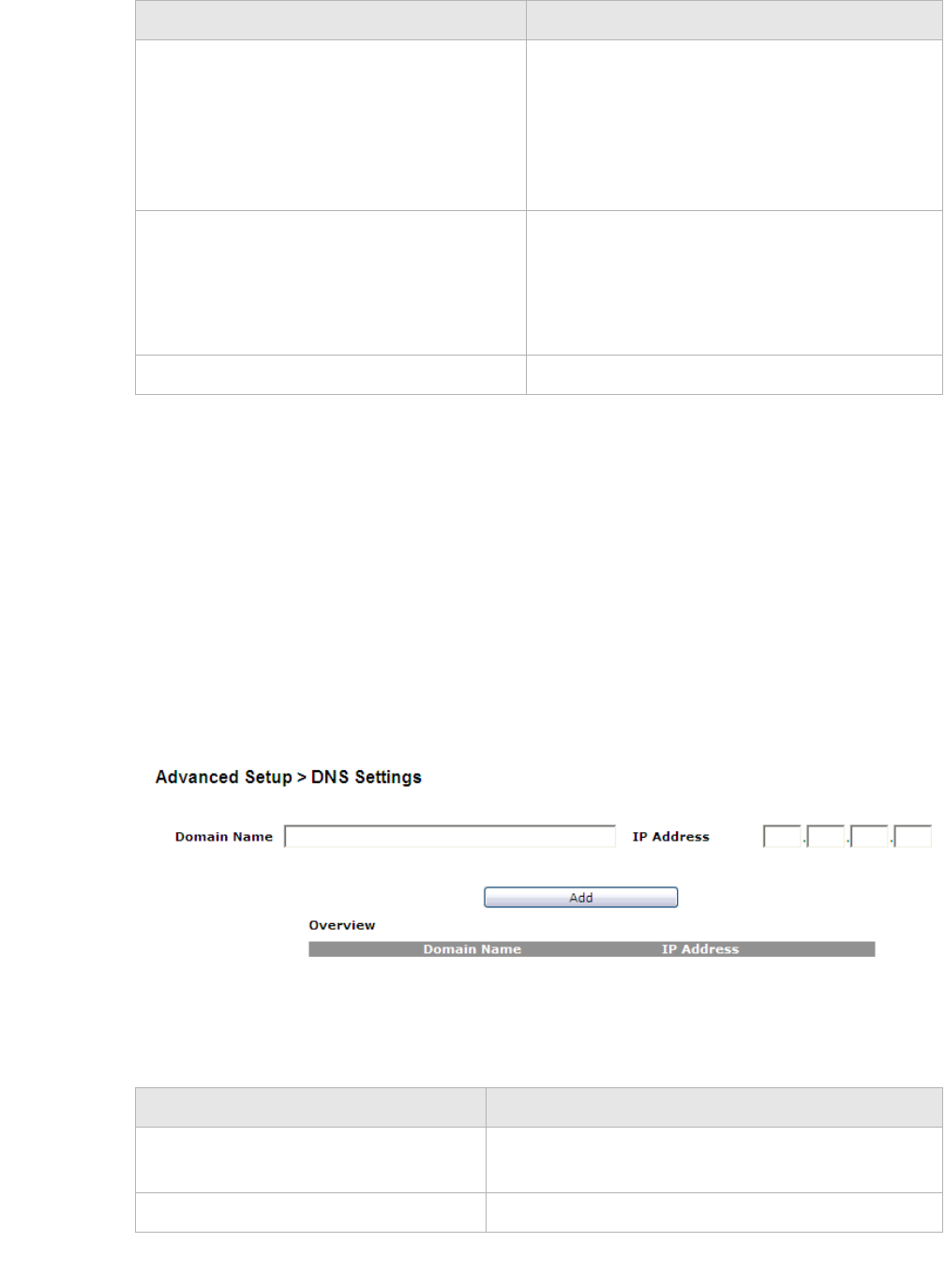
Advanced setupDNS Settings
............................................................................................................................................................................................................................................................
3EQ-10280-AAAA-TCZZA
Edition 01 February 2011 8-3
............................................................................................................................................................................................................................................................
DNS Settings
The DNS Settings window enables you to configure the domain name and IP address of
the domain name.
Note: You can set up to 64 entries.
Select DNS Settings in the Advanced Setup menu to access the DNS Settings window;
see Figure 8-2.
Figure 8-2 DNS Settings window
Table 8-2 describes the fields of the DNS Settings window.
Table 8-2 Field descriptions
Interface Select LAN or WAN(DHCP1) interface. The
packets sent to the addresses of the destination
IP address are sent through this interface.
However, for the WAN interface it will depend
on the WAN configuration you choose and how
it is defined.
Dynamic Routing Select Enable to use dynamic routing instead
of static. Dynamic routing enables the router to
adapt to changes in the network and exchange
rating tables with other routers. Select Disable
to turn off dynamic routing.
Apply Changes Click to save your changes.
Field Description
Field Description
Domain Name Enter the domain name to which you want to
connect.
IP Address Enter the IP address of the Static DNS.
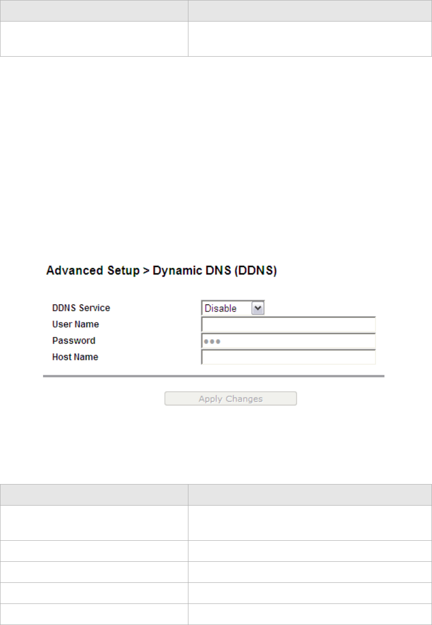
............................................................................................................................................................................................................................................................
Dynamic DNSAdvanced setup
8-4 3EQ-10280-AAAA-TCZZA
Edition 01 February 2011
............................................................................................................................................................................................................................................................
Dynamic DNS
The Dynamic DNS (DDNS) window enables you to configure your registered domain
name with a dynamic IP address.
Note: Before you can use this feature, you need to register for a DDNS service at
one of the supported DDNS service providers; see DynDNS.org or ChangeIP.com.
Click on Dynamic DNS in the Advanced Setup menu to access the Dynamic DNS
(DDNS) window; see Figure 8-3.
Figure 8-3 Dynamic DNS window
Table 8-3 describes the fields of the Dynamic DNS (DDNS) window.
Table 8-3 Field descriptions
Add Click to add the DNS settings and save your
changes.
Field Description
Field Description
DDNS Service If you have registered a DDNS, select the DDNS
service. Select Disable to turn off DDNS.
User Name Enter the username of your DDNS account.
Password Enter the password of your DDNS account.
Host Name Enter the host name.
Apply Changes Click to save your changes.
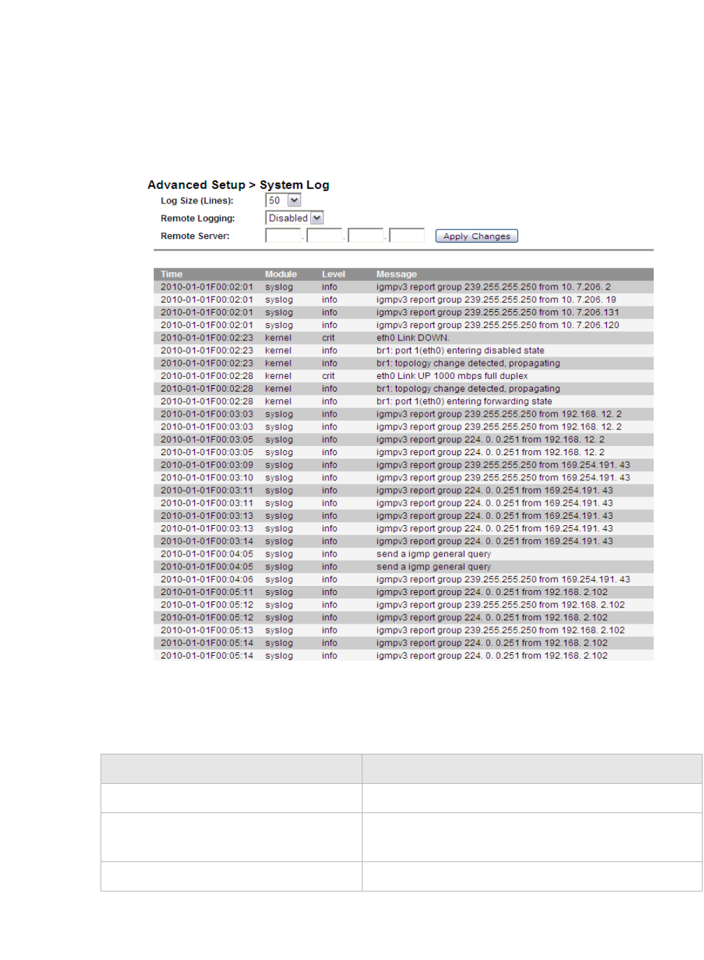
Advanced setupSystem Log
............................................................................................................................................................................................................................................................
3EQ-10280-AAAA-TCZZA
Edition 01 February 2011 8-5
............................................................................................................................................................................................................................................................
System Log
The System Log window enables you to view the system logs and to send them to a
remote system log server.
Click on System Log in the Advanced Setup menu to access the system log window; see
Figure 8-4.
Figure 8-4 System Log window
Table 8-4 describes the fields of the System Log window.
Table 8-4 Field descriptions
Field Description
Log Size (Lines) Select the number of lines to display in the log.
Remote Logging Select LAN or WAN for the remote logging server.
Select Disable to turn off remote logging.
Remote Server Enter the IP address of the remote logging server.

............................................................................................................................................................................................................................................................
IGMP Proxy/SnoopingAdvanced setup
8-6 3EQ-10280-AAAA-TCZZA
Edition 01 February 2011
............................................................................................................................................................................................................................................................
IGMP Proxy/Snooping
The IGMP Proxy/Snooping window enables you to setup LAN-side IGMP support that
enables the LAN-side user to receive multicast traffic.
Click on IGMP Proxy/Snooping in the Advanced Setup menu to access the IGMP
Proxy/Snooping window; see Figure 8-5.
Apply Changes Click to save your changes and to view the log.
If you are configuring remote logging, click Apply
Changes after modifying the remote logging and
remote server fields.
Time (read-only) The time that the event occurred.
Module (read-only) The type of module involved in the event.
Level (read-only) The level of logging activity:
•EMERG
•ALERT
•CRIT
•ERR
•WARNING
•NOTICE
•INFO
•DEBUG
Message The details of the event that occurred.
Field Description
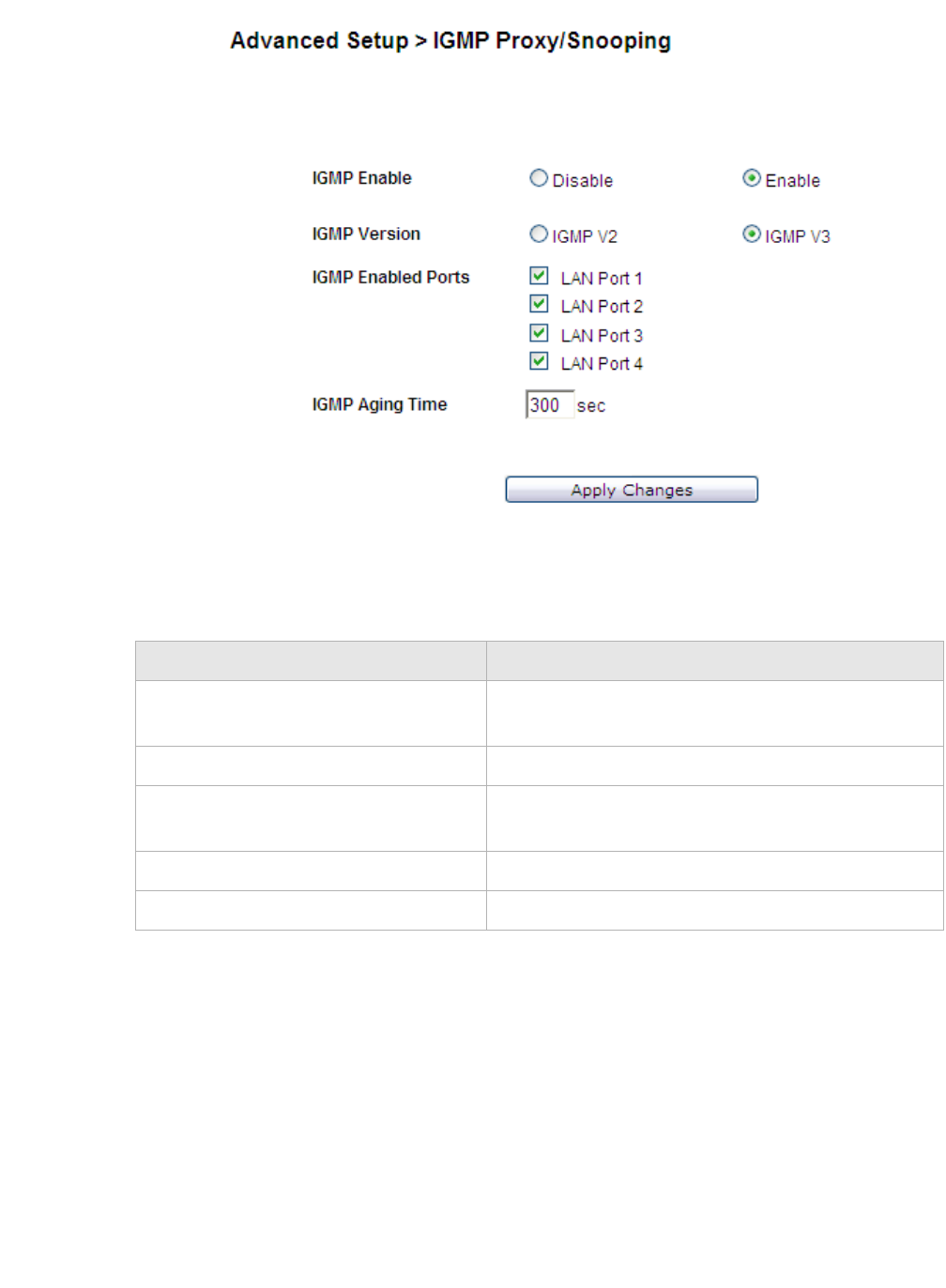
Advanced setup802.1x Config
............................................................................................................................................................................................................................................................
3EQ-10280-AAAA-TCZZA
Edition 01 February 2011 8-7
............................................................................................................................................................................................................................................................
Figure 8-5 IGMP Proxy/Snooping window
Table 8-5 describes the fields of the IGMP Proxy/Snooping window.
Table 8-5 Field descriptions
802.1x Config
The 802.1x Config window enables you to setup the 802.1x configuration. 802.1x is an
authentication mechanism for clients connecting to an IEEE 802 network such as Ethernet (access)
networks and 802.11 (public) wireless LANs.
Click on 802.1x Config in the Advanced Setup menu to access the 802.1x Config
window; see Figure 8-6.
Field Description
IGMP Enable Select Enable to allow IGMP support. Select
Disable to turn off IGMP support.
IGMP Version Select the IGMP version to use.
IGMP Enabled Ports Enable LAN Port 1 to 4 to enable IGMP support for
each selected LAN port.
IGMP Aging Time Enter the IGMP aging time in seconds.
Apply Changes Click to save your changes.
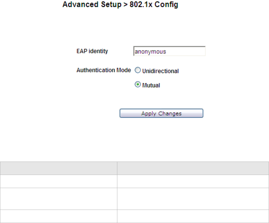
............................................................................................................................................................................................................................................................
802.1x ConfigAdvanced setup
8-8 3EQ-10280-AAAA-TCZZA
Edition 01 February 2011
............................................................................................................................................................................................................................................................
Figure 8-6 802.1 x Config window
Table 8-6 describes the fields of the 802.1x Config window.
Table 8-6 Field descriptions
Field Description
EAP identify Enter the EAP identity.
Authentication Mode Select Unidirectional or Mutual support for each
authentication mode.
Apply Changes Click to save your changes.

9-1
3EQ-10280-AAAA-TCZZA
Edition 01 February 2011
............................................................................................................................................................................................................................................................
9QoS PTM setup
Overview
This chapter explains how to configure the QoS settings via PTM. QoS is the ability to
provide better service to selected applications and data flows.
Click QoS PTM Setup in the main menu to open the QoS PTM Setup menu.
Contents
This chapter covers the following topics:
QoS Overview
The QoS Overview window allows you to see all current QoS PTM settings.
Select QoS Overview in the QoS PTM Setup menu to access the QoS Overview window;
see Figure 9-1.
QoS Overview 9-1
QoS Scheduler 9-2
QoS Policy 9-5
QoS Phone 9-7
QoS ALG 9-8
QoS Defaults 9-10
QoS MAC 9-12
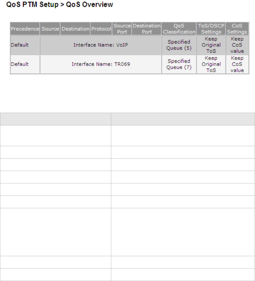
............................................................................................................................................................................................................................................................
QoS SchedulerQoS PTM setup
9-2 3EQ-10280-AAAA-TCZZA
Edition 01 February 2011
............................................................................................................................................................................................................................................................
Figure 9-1 QoS Overview window
Table 9-1 describes the fields of the QoS Overview window.
Table 9-1 Field descriptions
QoS Scheduler
The QoS Scheduler window allows you to enable and disable the scheduler protocol and
determine the upstream bandwidth.
Select QoS Scheduler in the QoS PTM Setup menu to access the QoS Scheduler window;
see Figure 9-2.
Field Description
Precedence (read-only) Presents the priority of each QoS rule (Precedence 1
is the highest priority).
Source (read-only) IP address of the source host.
Destination (read-only) IP address of the destination host.
Protocol (read-only) The protocol type for the QoS rule.
Source Port (read-only) Port number of the source host.
Destination Port (read-only) Port number of the destination host.
QoS Classification (read-only) The classification of the QoS rule:
•Original ToS Tag: the queue is assigned
according to the ToS value of incoming traffic.
•Specified Queue: incoming traffic is assigned
to a specific queue (0 to 7).
ToS/DSCP Settings (read-only) The ToS/DSCP marking setting for incoming traffic.
CoS Settings (read-only) CoS setting for the QoS rule.
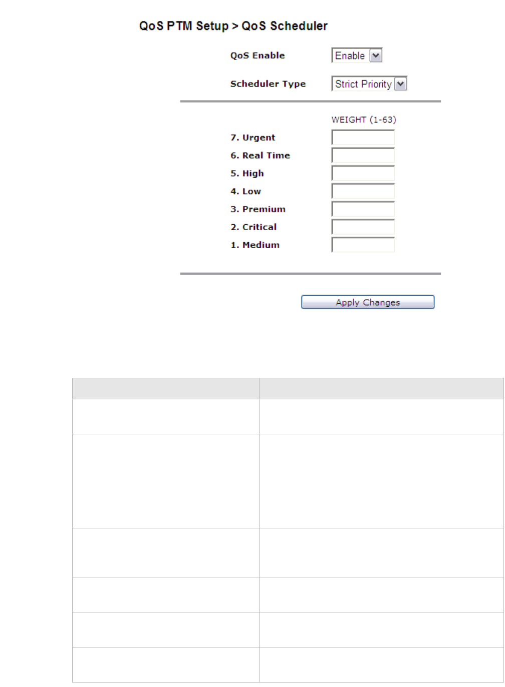
QoS PTM setupQoS Scheduler
............................................................................................................................................................................................................................................................
3EQ-10280-AAAA-TCZZA
Edition 01 February 2011 9-3
............................................................................................................................................................................................................................................................
Figure 9-2 QoS Upstream Scheduler window
Table 9-2 describes the fields of the QoS Upstream Scheduler window.
Table 9-2 Field descriptions
Field Description
QoS Enable Select Enable to activate the QoS scheduler. Select
Disable to turn off the QoS scheduler.
Scheduler Type Select the QoS scheduler type:
•Strict Priority: delivers high priority (7 is the
highest) traffic first and then lower priority
traffic when higher queues are empty.
•Min - Max Bandwidth: specifies the minimum
and maximum bandwidth for each queue.
Aggregate Rate Limiter Enter an upstream bandwidth value from 100 to
200000 Kb/s for your WAN connection. The default
value is 50000 Kb/s.
7. Urgent Specify the minimum and maximum bandwidth for
the urgent queue.
6. Real Time Specify the minimum and maximum bandwidth for
the real-time queue.
5. High Specify the minimum and maximum bandwidth for
the high queue.

............................................................................................................................................................................................................................................................
QoS PTM setup
9-4 3EQ-10280-AAAA-TCZZA
Edition 01 February 2011
............................................................................................................................................................................................................................................................
4. Low Specify the minimum and maximum bandwidth for
the low queue.
3. Premium Specify the minimum and maximum bandwidth for
the premium queue.
2. Critical Specify the minimum and maximum bandwidth for
the critical queue.
1. Medium Specify the minimum and maximum bandwidth for
the medium queue.
Apply Changes Click to save your changes.
Field Description
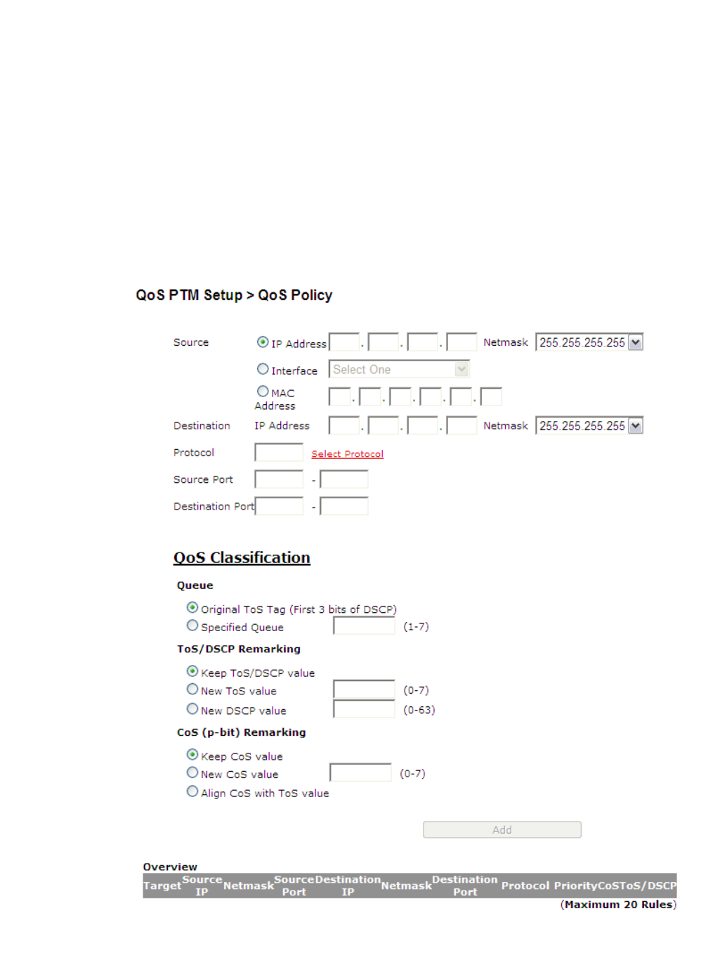
QoS PTM setupQoS Policy
............................................................................................................................................................................................................................................................
3EQ-10280-AAAA-TCZZA
Edition 01 February 2011 9-5
............................................................................................................................................................................................................................................................
QoS Policy
The QoS Policy window enables you to group upstream traffic into data flows according
to the source address, destination address, source port, and destination port.
Select QoS Policy in the QoS PTM Setup menu to access the QoS Policy window; see
Figure 9-3.
Figure 9-3 QoS Policy window
Table 9-3 describes the fields of the QoS Policy window.

............................................................................................................................................................................................................................................................
QoS PolicyQoS PTM setup
9-6 3EQ-10280-AAAA-TCZZA
Edition 01 February 2011
............................................................................................................................................................................................................................................................
Table 9-3 Field descriptions
Field Description
Source
IP Address Select the radio button and enter the IP address of the
source host.
Netmask Select the subnet mask of the source host.
Interface Select the radio button and select a connection to
configure its QoS policy.
MAC Address Select the radio button and enter the MAC address.
Destination
IP Address Enter the IP address of the destination host.
Netmask Select the subnet mask of the destination host.
Protocol Click Select Protocol to choose a protocol.
Source Port Enter the range of source ports for this QoS policy.
Destination Port Enter the range of destination ports for this QoS policy.
QoS Classification
Queue Select one of the following:
•Original ToS Tag to assign the queue according to
the incoming ToS value.
•Specified Queue and enter a queue number (0 to
7) to assign to the incoming traffic.
ToS/DSCP Remarking Select one of the following:
•Keep Original ToS/DSCP to retain the original
value.
•New ToS Value and enter a queue number (0 to 7)
to assign to the incoming traffic.
•New DSCP Value and enter a DSCP value (0 to
63).
CoS (p-bit) Remarking Select one of the following:
•Keep CoS Value to retain the original value.
•New CoS Value to set a new CoS value for
incoming traffic.
•Align CoS with ToS value to set CoS same as the
ToS value for incoming traffic.
Add Click to add the policy and save your changes.
Overview
Target Upstream or Downstream. Target 1 is the highest
priority.

QoS PTM setupQoS Phone
............................................................................................................................................................................................................................................................
3EQ-10280-AAAA-TCZZA
Edition 01 February 2011 9-7
............................................................................................................................................................................................................................................................
QoS Phone
The QoS Phone window enables you to configure DSCP value and CoS value of SIP and
RTP Sessions.
Select QoS Phone in the QoS PTM Setup menu to access the QoS Phone window; see
Figure 9-4.
Source IP IP address of the source host.
Netmask Subnet mask of the source IP address.
Source Port Port number of the source host.
Destination IP IP address of the destination host.
Netmask Subnet mask of the destination IP address.
Destination Port Port number of the destination host.
Protocol The protocol type for this QoS policy.
Priority The priority queue (0 to 7) used by the traffic.
CoS CoS value of the QoS policy.
ToS/DSCP ToS/DSCP marking setting for incoming traffic.
Change Precedence Select a QoS rule precedence number and then select
where to move it:
•Up: move this QoS rule to higher priority.
•Down: move this QoS rule to lower priority.
•Delete: remove this QoS rule.
Click Apply to change the precedence.
Field Description
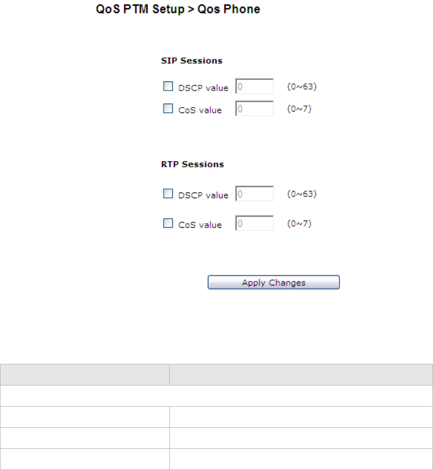
............................................................................................................................................................................................................................................................
QoS ALGQoS PTM setup
9-8 3EQ-10280-AAAA-TCZZA
Edition 01 February 2011
............................................................................................................................................................................................................................................................
Figure 9-4 QoS Phone window
Table 9-4 describes the fields of the QoS Phone window.
Table 9-4 Field descriptions
QoS ALG
The QoS ALG window enables you to configure SIP and RTP. SIP is used by VoIP and
RTP is the protocol for transferring real-time data (such as interactive audio and video).
Select QoS ALG in the QoS PTM Setup menu to access the QoS ALG window; see
Figure 9-5.
Field Description
SIP Sessions/RTP Sessions
DSCP value Check the check box to enter a DSCP value (0 to 63).
CoS value Check the check box to enter a CoS value (0 to 7).
Apply Changes Click to save your changes.
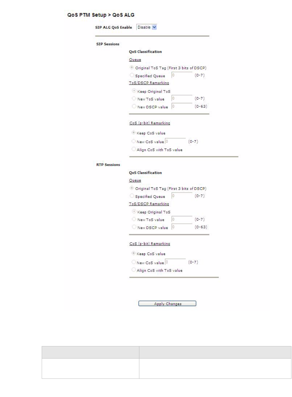
QoS PTM setupQoS ALG
............................................................................................................................................................................................................................................................
3EQ-10280-AAAA-TCZZA
Edition 01 February 2011 9-9
............................................................................................................................................................................................................................................................
Figure 9-5 QoS ALG window
Table 9-5 describes the fields of the QoS ALG window.
Table 9-5 Field descriptions
Field Description
SIP ALG QoS Enable Select Enable to turn on the SIP ALG QoS. Select
Disable to turn off the SIP ALG QoS.

............................................................................................................................................................................................................................................................
QoS DefaultsQoS PTM setup
9-10 3EQ-10280-AAAA-TCZZA
Edition 01 February 2011
............................................................................................................................................................................................................................................................
QoS Defaults
The QoS Defaults window enables you to configure the default QoS policy for each WAN
connection.
Select QoS Defaults in the QoS PTM Setup menu to access the QoS Defaults window; see
Figure 9-6.
SIP Sessions/RTP Sessions
Queue Select one of the following:
•Original ToS Tag to assign the queue according to
the incoming ToS value.
•Specified Queue and enter a queue number (0 to
7) to assign to the incoming traffic.
ToS/DSCP Remarking Select one of the following:
•Keep Original ToS/DSCP to retain the original
value.
•New ToS Value and enter a queue number (0 to 7)
to assign to the incoming traffic.
•New DSCP Value and enter a DSCP value (0 to 63).
CoS (p-bit) Remarking Select one of the following:
•Keep CoS Value to retain the original value.
•New CoS Value to set a new CoS value for
incoming traffic.
•Align CoS with ToS value to set CoS same as the
ToS value for incoming traffic.
Apply Changes Click to save your changes.
Field Description
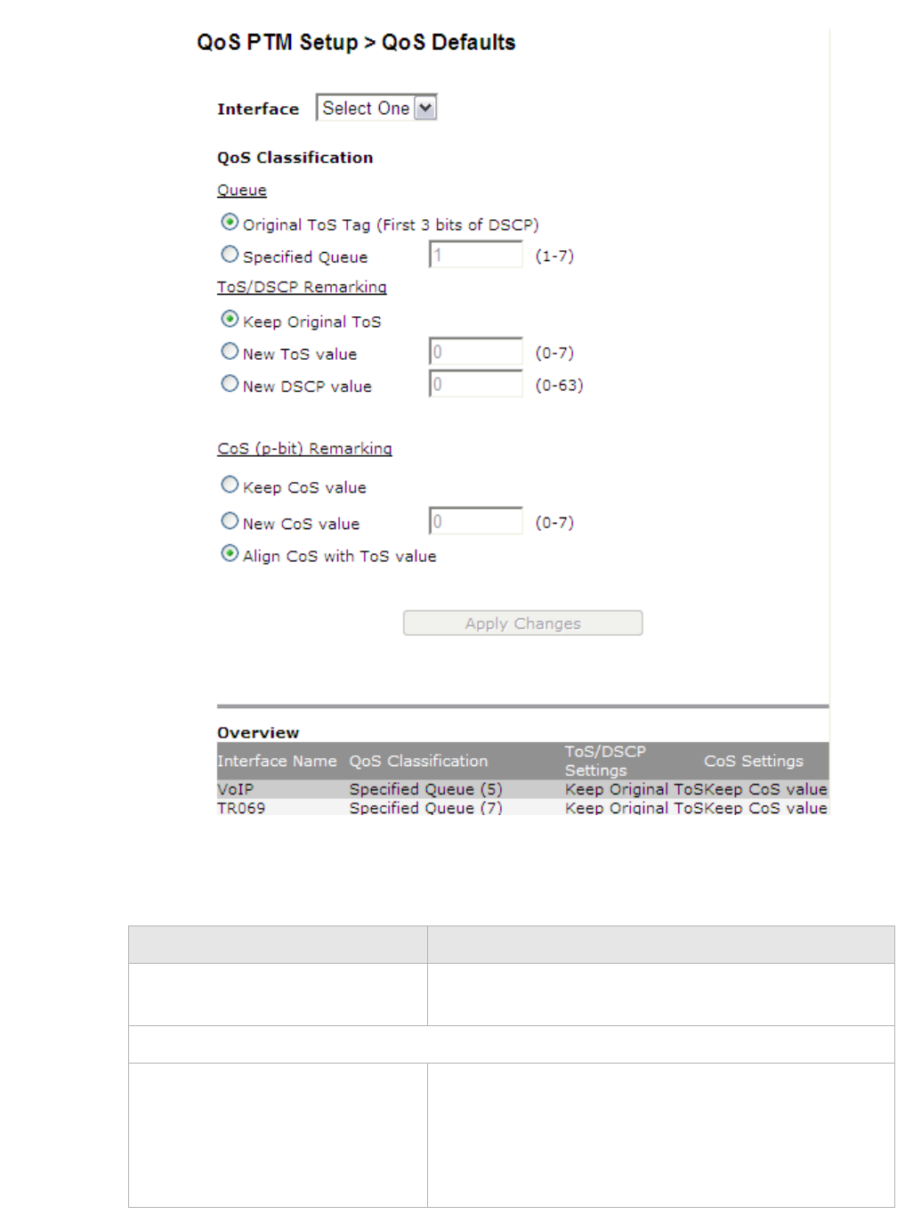
QoS PTM setupQoS Defaults
............................................................................................................................................................................................................................................................
3EQ-10280-AAAA-TCZZA
Edition 01 February 2011 9-11
............................................................................................................................................................................................................................................................
Figure 9-6 QoS Defaults window
Table 9-6 describes the fields of the QoS Defaults window.
Table 9-6 Field descriptions
Field Description
Interface Select a WAN connection to configure its default QoS
policy.
QoS Upstream Classification
Queue Select one of the following:
•Original ToS Tag to assign the queue according to
the incoming ToS value.
•Specified Queue and enter a queue number (1 to
7) to assign to the incoming traffic.

............................................................................................................................................................................................................................................................
QoS MACQoS PTM setup
9-12 3EQ-10280-AAAA-TCZZA
Edition 01 February 2011
............................................................................................................................................................................................................................................................
QoS MAC
The QoS MAC window enables you to configure a QoS policy for a specific device by
MAC address when the gateway is operating in bridge mode.
Select QoS MAC in the QoS PTM Setup menu to access the QoS MAC window; see
Figure 9-7.
ToS/DSCP Remarking Select one of the following:
•Keep Original ToS/DSCP to retain the original
value.
•New ToS Value and enter a queue number (0 to 7)
to assign to the incoming traffic.
•New DSCP Value and enter a DSCP value (0 to 63).
CoS (p-bit) Remarking Select one of the following:
•Keep CoS Value to retain the original value.
•New CoS Value to set a new CoS value for
incoming traffic.
•Align CoS with ToS value to set CoS same as the
ToS value for incoming traffic.
Overview
Interface Name The Interface name of WAN connection to configure its
QoS policy.
QoS Upstream Classification The classification of the QoS rule:
•Original ToS Tag: the queue is assigned according
to the ToS value of incoming traffic.
•Specified Queue: incoming traffic is assigned to a
specific queue (0 to 7).
ToS/DSCP Settings The ToS/DSCP marking setting for incoming traffic.
CoS Settings CoS setting for the QoS rule.
Field Description
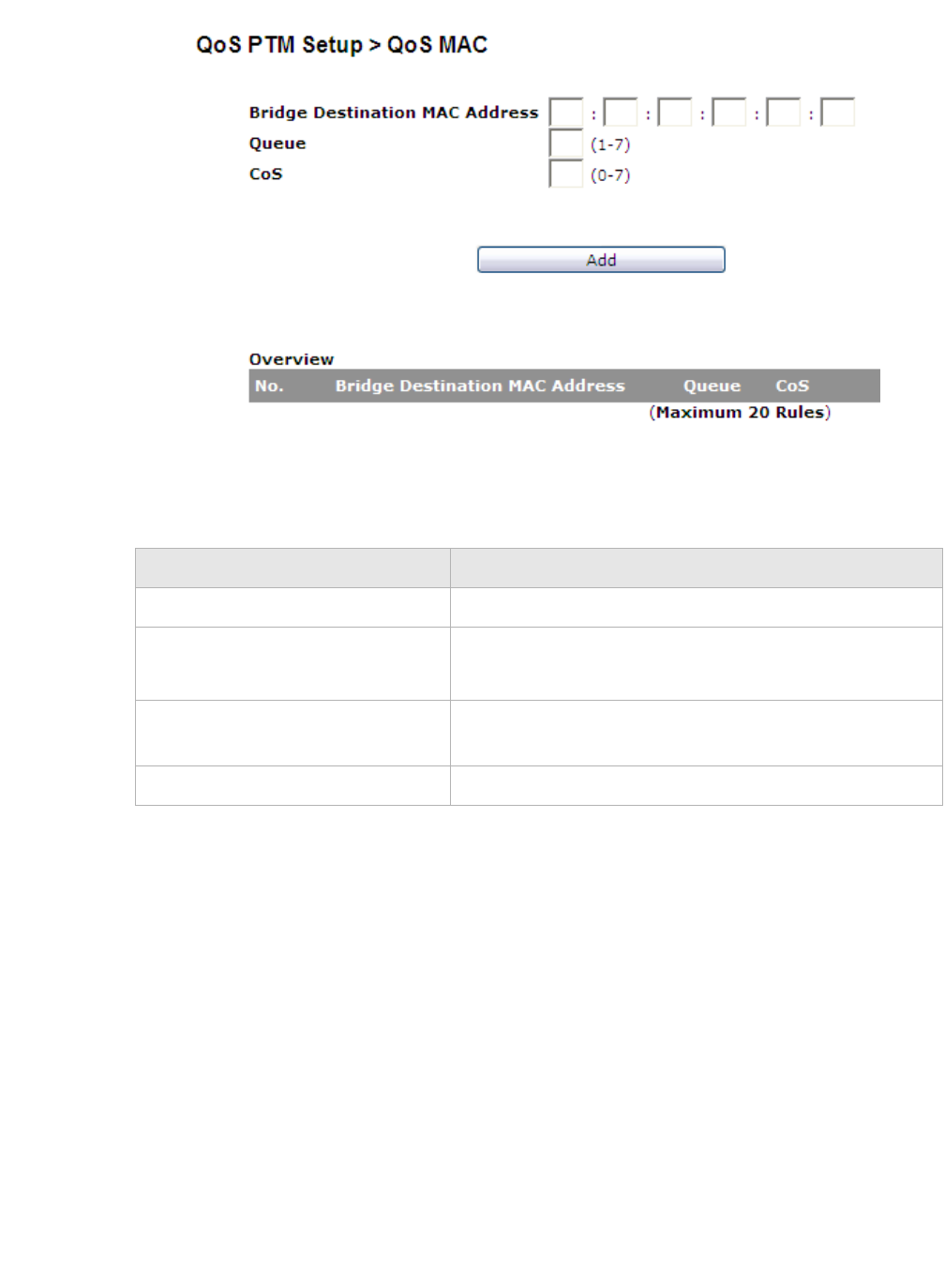
QoS PTM setupQoS MAC
............................................................................................................................................................................................................................................................
3EQ-10280-AAAA-TCZZA
Edition 01 February 2011 9-13
............................................................................................................................................................................................................................................................
Figure 9-7 QoS MAC window
Table 9-7 describes the fields of the QoS MAC window.
Table 9-7 Field descriptions
Field Description
Bridge Destination MAC Address Specify the MAC address of QoS service user.
Queue Specify which queue (1 to 7) will be assigned to this
MAC address.
CoS Specify the CoS value (0 to 7) that will be marked on
packets coming from the MAC address.
Add Click to add the rule.
............................................................................................................................................................................................................................................................
QoS MACQoS PTM setup
9-14 3EQ-10280-AAAA-TCZZA
Edition 01 February 2011
............................................................................................................................................................................................................................................................

10-1
3EQ-10280-AAAA-TCZZA
Edition 01 February 2011
............................................................................................................................................................................................................................................................
10 Telephony
Overview
The CellPipe 7130 RG Telephony menu enables you to configure the settings for your
VoIP account and view the calling log.
Click the Telep ho ny drop-down menu to open the Tel e phony menu.
Contents
This chapter covers the following topics.
Account Setup
Your VoIP account setup can be configured here.
Note: Some account information, such as the phone number and username, is
provided by your VoIP service provider. Please have all the provided information
handy when configuring your accounts.
Select Account Setup in the Telep h o n y menu to access the Account Setup window; see
Figure 10-1.
Account Setup 10-1
Service Settings 10-4
SIP Server Settings 10-8
RTP/Codecs settings 10-10
Account & Line Table 10-12
Call History 10-13
Other Settings 10-14
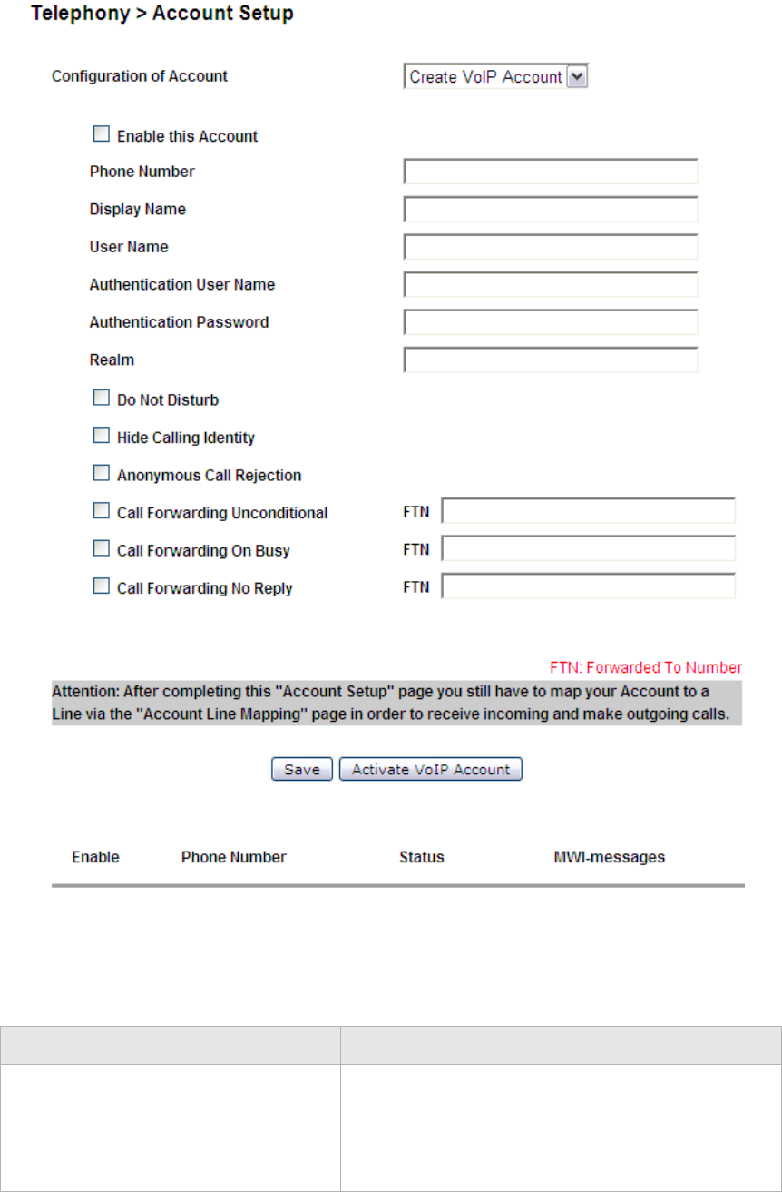
............................................................................................................................................................................................................................................................
Account SetupTelephony
10-2 3EQ-10280-AAAA-TCZZA
Edition 01 February 2011
............................................................................................................................................................................................................................................................
Figure 10-1 Account Setup window
Table 10-1 describes the fields of the Account Setup window.
Table 10-1 Field descriptions
Field Description
Configuration of Account Select a VoIP account to configure or select Create
VoIP Account to configure a new account.
Enable this Account Check the check box to enable the account to
register to the VoIP service provider.

Account SetupTelephony
............................................................................................................................................................................................................................................................
3EQ-10280-AAAA-TCZZA
Edition 01 February 2011 10-3
............................................................................................................................................................................................................................................................
Phone Number Enter the phone number of the account.
Display Name Enter the display name for the account.
User Name The user part of the Address of Record SIP URI.
Authentication User Name Enter the username of the account.
Authentication Password Enter the password for the username.
Realm Enter the realm for the account to authenticate.
Do Not Disturb When the checkbox is "checked" the Do Not Disturb
feature is activated. This will block all incoming
phone calls to this number. The phone will not ring
when this service is activated.
Hide Calling Identity When the checkbox is "checked" the "Hide Calling
identity" feature is activated. This will hide your
identity when you make outgoing calls.
Anonymous Call Rejection When the checkbox is "checked" the Anonymous
Call Rejection" feature is activated. This will block
an incoming call in case the remote party has
activated the "Hide Calling Identity" feature for that
call. So anynymous calls are rejected by the system
when this service is activated.
Call Forwarding Unconditional When the checkbox is "checked" the "Call
Forwarding Unconditional" feature is activated. You
must enter a phone number in the Forward To
Number (FTN) field. The system will forward an
incoming call to this FTN when this VoIP account is
busy.
Call Forwarding On Busy When the checkbox is "checked" the "Call
Forwarding on Busy" feature is activated.You must
enter a phone number in the Forward To Number
(FTN) field. The system will forward an incoming
call to this FTN.
Call Forwarding No Reply When the checkbox is "checked" the "Call
Forwarding No Reply" feature is activated. You
must enter a phone number in the Forward To
Number (FTN) field. The system will forward an
incoming call to this FTN when this VoIP account is
busy.
Save Click to save your changes.
Activate VoIP Account Click to register your account with your VoIP
service provider.
Field Description
............................................................................................................................................................................................................................................................
Service SettingsTelephony
10-4 3EQ-10280-AAAA-TCZZA
Edition 01 February 2011
............................................................................................................................................................................................................................................................
Note: If you checked all these three features: Do Not Disturb, Anonymous Call
Rejection and Call Forwarding Unconditional, The priorities are:
1. Do Not Disturb.
2. Anonymous Call Rejection.
3. Call Forwarding Unconditional.
For example, an incoming call will be rejected and the caller will receive a busy signal;
the call will not be rejected if anonymous, nor forwarded to the specified number.
Service Settings
The Service Settings window enables you to configure advanced settings for the VoIP
accounts such as call waiting and third party conference call.
Note: Changes made to the service settings apply to all VoIP accounts.
It is recommended that you contact your VoIP service provider for assistance with
configuring the service settings. Depending on your account, some features might not
be available.
Select Service Settings in the Tele p ho n y menu to access the Service Settings window;
see Figure 10-2.
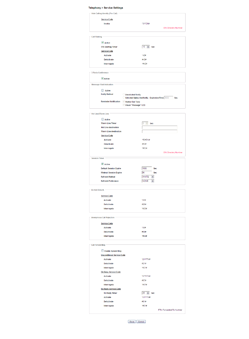
Service SettingsTelephony
............................................................................................................................................................................................................................................................
3EQ-10280-AAAA-TCZZA
Edition 01 February 2011 10-5
............................................................................................................................................................................................................................................................
Figure 10-2 Service Settings window
Table 10-2 describes the fields of the Service Settings window.

............................................................................................................................................................................................................................................................
Service SettingsTelephony
10-6 3EQ-10280-AAAA-TCZZA
Edition 01 February 2011
............................................................................................................................................................................................................................................................
Table 10-2 Field descriptions
Field Description
Hide Calling Identity (Per Call)
Service Code The activation code for hiding your account
information when making a call.
Call Waiting
Active Enable Active to turn on call waiting.
CW Alerting Timer Select a time interval for the call waiting alert.
Service Code The service codes for activation, deactivation,
and interrogation.
3 Party Conference
Active Enable Active to turn on conference call.
Message Wait Indication
Active Enable Active to turn on the message wait
indicator when a message has been received.
Notify Method Enable a method of notification for message
wait indication:
•Unsolicited: The CellPipe 7130 RG is
able to receive unsolicited "message wait"
NOTIFY messages. No SUBSCRIBE is
used.
•Subscribe/Notify: The CellPipe 7130 RG
will initiate a SUBSCRIBE/NOTIFY
dialogue in which "message wait" NOTIFY
messages will be received. Enter the
number of seconds that your VoIP service
should provide. It is the expire time in
seconds of your subscription to the
voicemail service. The SIP user agent will
refresh this subscription automatically
before this timer runs out.
Reminder Notification Enable one of the following as the message
wait indication:
•If Stutter Dial Tone is selected to
indicate a new message has arrived, a
stutter dial tone will be played when the
phone is off the hook.
•If Visual “Message” LED is selected to
indicated a new message has arrived, the
Message LED on the front panel of the
CellPipe 7130 RG will start blinking.
Hot Line/Warm Line

Service SettingsTelephony
............................................................................................................................................................................................................................................................
3EQ-10280-AAAA-TCZZA
Edition 01 February 2011 10-7
............................................................................................................................................................................................................................................................
Active Enable Active to use the hot line and warm line
feature.
Warm Line Timer Select a time period from the drop-down menu.
Warm line will be activated after the timer has
expired.
Hot Line destination Enter a destination phone number for the hot
line. When hot line is activated, picking up the
phone will automatically place a call to the hot
line destination.
Warm Line destination Enter a destination phone number for the warm
line. When warm line is activated, picking up
the phone will automatically place a call to the
warm line destination after the warm line timer
has expired.
Service Code The service codes for activation, deactivation,
and interrogation.
Session Timer
Active Enable Active to turn on the session timer.
When session timer is enabled, the CellPipe
7130 RG will periodically send a refresh
message to refresh the session.
Default Session Expire Enter the default number of seconds SIP
session can remain idle before automatically
disconnecting. Default value is 1800.
Minimal Session Expire Enter the minimum number of seconds SIP
session can remain idle before automatically
disconnecting. Minimun value is 90.
Refresh Method Select Invite or Update from the drop-down
menu. This will be the type of message to send
for refreshing session.
Refresh Preference Select a refresher preference from the drop-
down menu. Select None to let CellPipe 7130
RG decide. Select UAC to let caller refresh the
session. Select UAS to let the receiver of the
call refresh the session.
Don’t Disturb
Service Code The service codes for activation, deactivation,
and interrogation of your do not disturb service.
Anonymous Call Rejection
Field Description

............................................................................................................................................................................................................................................................
SIP Server SettingsTelephony
10-8 3EQ-10280-AAAA-TCZZA
Edition 01 February 2011
............................................................................................................................................................................................................................................................
SIP Server Settings
The Server Settings window enables you to configure the session initiated protocol (SIP)
settings for the VoIP accounts.
Note: It is recommended that you contact your VoIP service provider for assistance
with configuring the server settings.
Select SIP Server Settings in the Teleph o n y menu to access the Server Settings window;
see Figure 10-3.
Service Code The service codes for activation, deactivation,
and interrogation of your anonymous call
rejection service.
Call Forwarding
Enable Splash Ring Enable to receive a reminder when a incoming
call is forwarded unconditionally.
Unconditional Service Code The unconditional service codes for activation,
deactivation, and interrogation of your call
forwarding service.
On Busy Service Code The on busy service codes for activation,
deactivation, and interrogation of your call
forwarding service.
No Reply Service Code Select a time in seconds that the incoming call
should wait before being forwarded. The
default value is 20 seconds.
The no reply service codes for activation,
deactivation, and interrogation of your call
forwarding service.
Save Click to save your changes.
Cancel Click to clear your settings.
Field Description
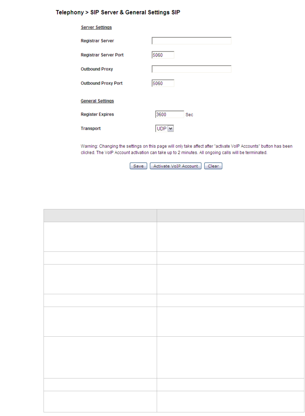
SIP Server SettingsTelephony
............................................................................................................................................................................................................................................................
3EQ-10280-AAAA-TCZZA
Edition 01 February 2011 10-9
............................................................................................................................................................................................................................................................
Figure 10-3 SIP Server Settings window
Table 10-3 describes the fields of the SIP Server Settings window.
Table 10-3 Field descriptions
Field Description
Registrar Server Enter the Fully Qualified Domain Name (FQDN) or
IP address of the SIP registrar server of your VoIP
provider.
Registrar Server Port Enter the port number of the SIP registration server.
Outbound Proxy Enter the Fully Qualified Domain Name (FQDN) or
IP address of the Outbound Proxy server of your
Vo I P p r o v i d e r.
Outbound Proxy Port Enter the port number of the outbound proxy server.
Register Expires Enter the number of seconds that your SIP account is
registered with the SIP registrar server before it is
deleted. The default value is 3600 seconds.
Transport Select the appropriate transport protocol for the user
agent:
•UDP
•TCP
Save Click to save your changes.
Activate VoIP Account Click to register the account with your VoIP service
provider.

............................................................................................................................................................................................................................................................
RTP/Codecs settingsTelephony
10-10 3EQ-10280-AAAA-TCZZA
Edition 01 February 2011
............................................................................................................................................................................................................................................................
RTP/Codecs settings
The RTP/Codecs settings window allows you to setup the codecs and ports for your voice
traffic.
A codec (coder/decoder) codes analog voice signals into digital signals and decodes the
digital signals back into analog voice signals. Select RTP/Codecs Settings in the
Telephon y menu to access the RTP/Codecs Settings window; see Figure 10-4.
Clear Click to clear your settings.
Field Description
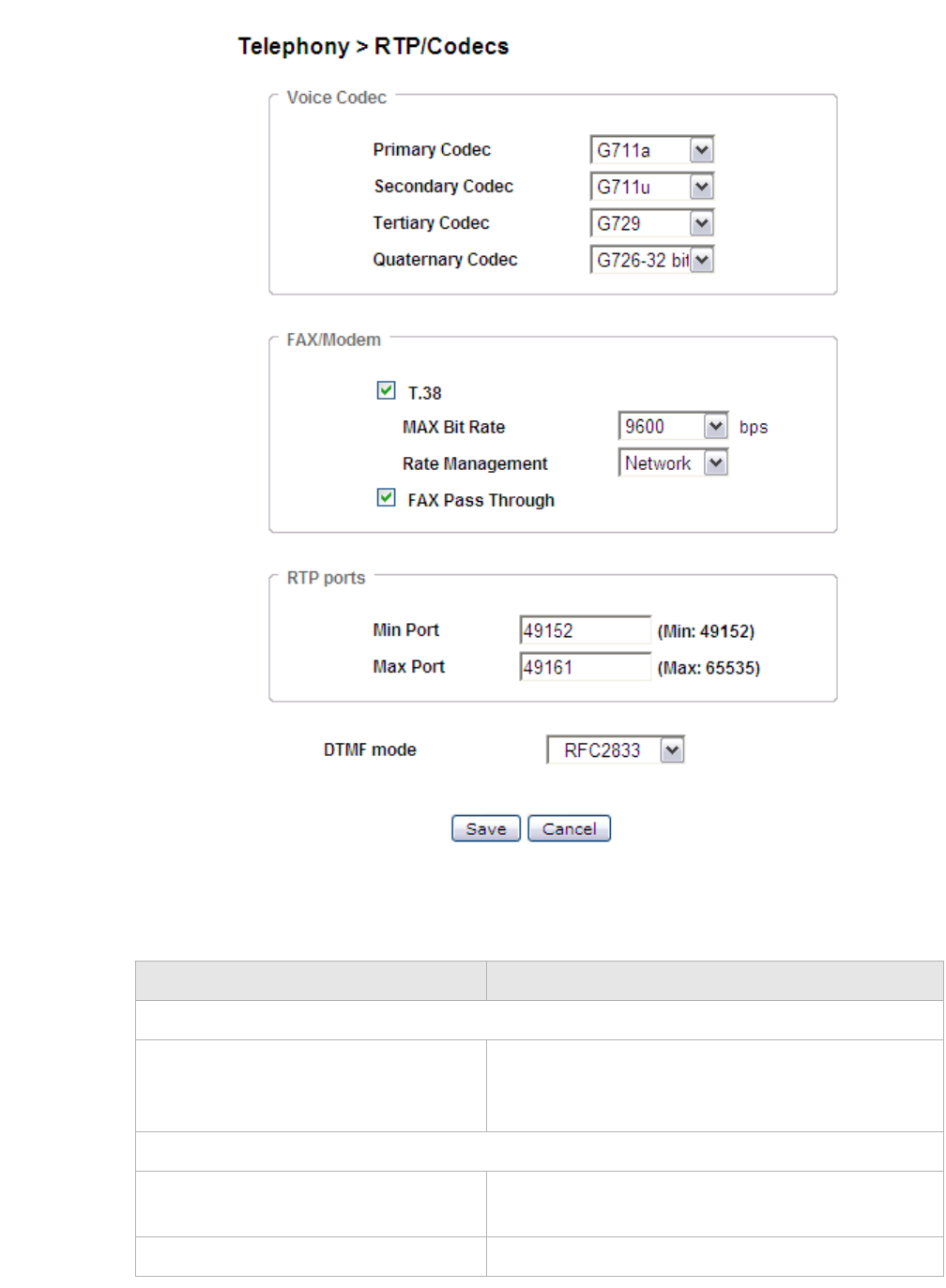
RTP/Codecs settingsTelephony
............................................................................................................................................................................................................................................................
3EQ-10280-AAAA-TCZZA
Edition 01 February 2011 10-11
............................................................................................................................................................................................................................................................
Figure 10-4 RTP/Codecs Settings window
Table 10-4 describes the fields of the RTP/Codecs Settings window.
Table 10-4 Field descriptions
Field Description
Voice Codec
Primary Codec/Secondary
Codec/Tertiary Codec/Quaternary
Codec
Select the priorities of your codec.
Fax/Modem
T.38 Enable to allow the device to send fax messages
through IP networks.
MAX Bit Rate Select the maximum bit rate in b/s for fax messages.

............................................................................................................................................................................................................................................................
Account & Line TableTelephony
10-12 3EQ-10280-AAAA-TCZZA
Edition 01 February 2011
............................................................................................................................................................................................................................................................
Account & Line Table
The Account & Line Table enables you to specify which VoIP accounts are associated
with your phone ports/lines.
Select Account & Line Table in the Tel eph o ny menu to access the Account & Line Table
window; see Figure 10-5.
Rate Management Select the data rate management:
•Select Network data rate management to
require that the training signal be transferred
over the network.
•Select Local data rate management to require
that the training signal be generated locally.
The default is Network.
Fax Pass Through Enable to apply fax passthrough.
RTP Ports
Min Port Enter the minimum port of the RTP listening port
range.
Max Port Enter the maximum port of the RTP listening port
range.
DTMF Mode Select how the device handles the tones that your
telephone makes when the phone buttons are
pressed.
•Select RFC2833 to send the DTMF tones in
RTP packets.
•Select SIP INFO to send the DTMF tones in SIP
messages.
•Select INBAND to send the DTMF tones in the
voice data stream.
Note: Please consult your VoIP service provider
for details.
Save Click to save your changes.
Cancel Click to clear your settings.
Field Description
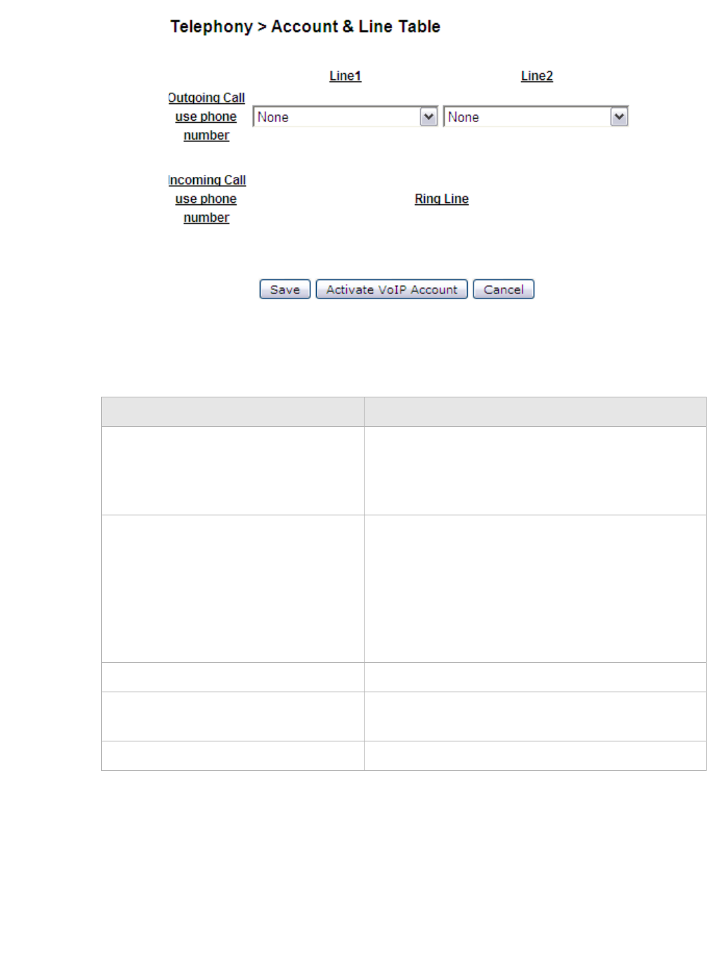
Call HistoryTelephony
............................................................................................................................................................................................................................................................
3EQ-10280-AAAA-TCZZA
Edition 01 February 2011 10-13
............................................................................................................................................................................................................................................................
Figure 10-5 Account and Line Table window
Table 10-5 describes the fields of the Account & Line Table window.
Table 10-5 Field descriptions
Call History
The Call History window displays the call statistics and call log of your VoIP accounts.
Select Call History in the Tel e pho n y menu to access the Call History window; see
Figure 10-6.
Field Description
Outgoing Call use phone number Select the VoIP account to be associated with Line1
and Line2. This VoIP account (phone number) will
be used as the "Calling number" when initiating a
call from the corresponding Line.
Incoming Call use phone number Select which Line will ring when you receive an
incoming call for a certain VoIP account (phone
number). When you create a VoIP account, a phone
number is added by the system in the "Incoming
Call use phone number" list. When you delete a
VoIP account, the corresponding phone number is
removed from this list.
Save Click to save your changes.
Activate VoIP Account Click to register the account with your VoIP service
provider.
Cancel Click to clear your settings.
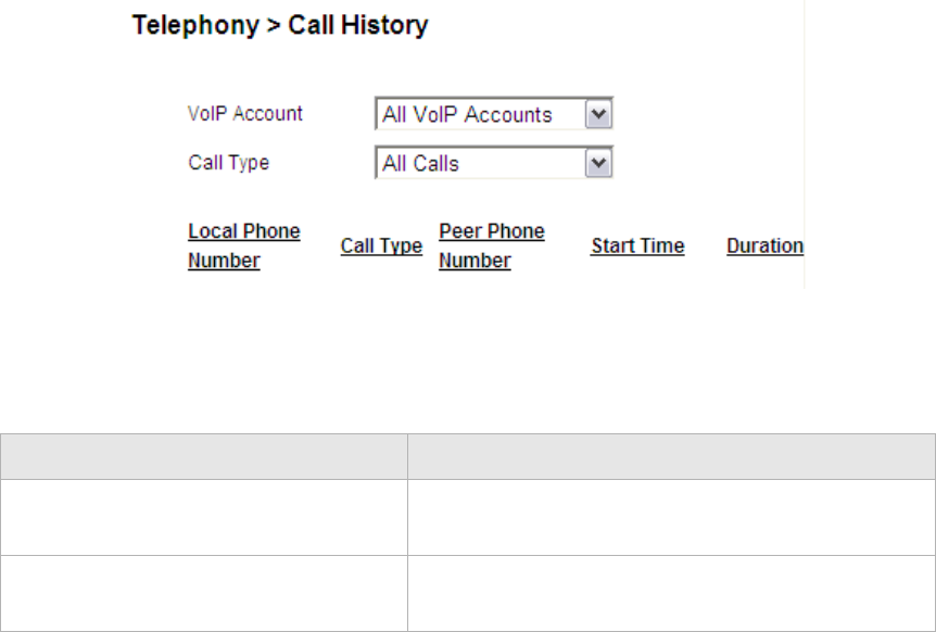
............................................................................................................................................................................................................................................................
Other SettingsTelephony
10-14 3EQ-10280-AAAA-TCZZA
Edition 01 February 2011
............................................................................................................................................................................................................................................................
Figure 10-6 Call History window
Table 10-6 describes the fields of the Call History window.
Table 10-6 Field descriptions
Other Settings
The Other Settings window allows you to change the profile for various countries in order
for that country’s telephone to operate.
Select Other Settings in the Te l e ph on y menu to access the Other Settings window; see
Figure 10-7.
Field Description
VoIP Account Select the VoIP account(s) to display the selected
account(s) statistics and logs.
Call type Select the type of calls to display the specified type
of calls statistics and logs.
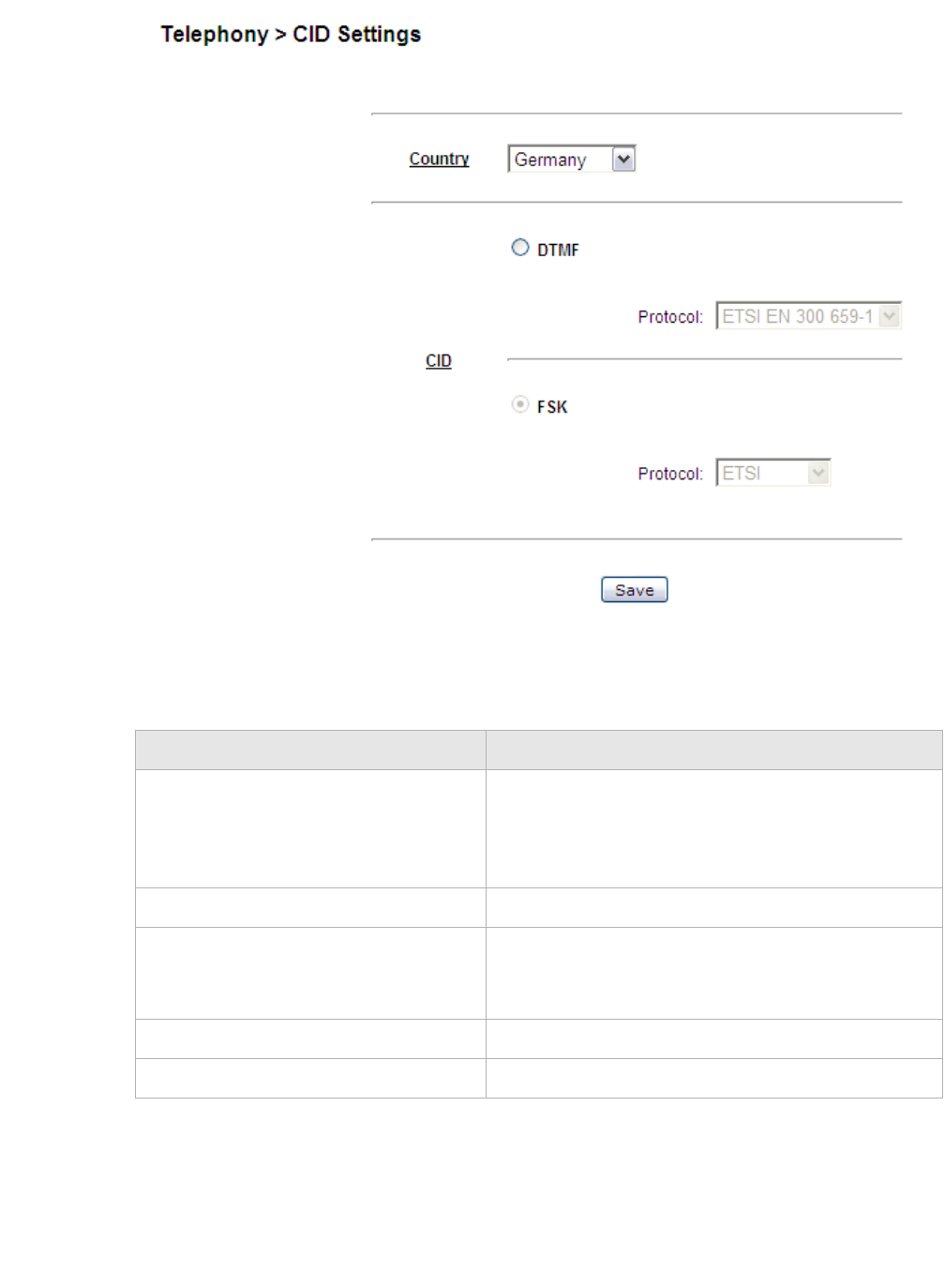
Other SettingsTelephony
............................................................................................................................................................................................................................................................
3EQ-10280-AAAA-TCZZA
Edition 01 February 2011 10-15
............................................................................................................................................................................................................................................................
Figure 10-7 Other Settings window
Table 10-7 describes the fields of the Other Settings window.
Table 10-7 Field descriptions
Field Description
Country Select a country from the list. It will change ring
cadence, impedence and DC feed settings to meet
that country's requirement. You must reboot the
CellPipe 7130 RG for your changes to take effect.
DTMF Only one protocol is available, ETSI EN 300 659-1
CID Choose between two different types of CID to
specify how the CID are transmitted to the phone.
Each CID type has its own protocols.
FSK Choose between ETSI or Telecordia.
Save Click to save your changes.
............................................................................................................................................................................................................................................................
Other SettingsTelephony
10-16 3EQ-10280-AAAA-TCZZA
Edition 01 February 2011
............................................................................................................................................................................................................................................................

11-1
3EQ-10280-AAAA-TCZZA
Edition 01 February 2011
............................................................................................................................................................................................................................................................
11 Utilities
Overview
This chapter explains how to configure the utilities of the CellPipe 7130 RG.
Click Utilities in the main menu to open the Utilities menu.
Contents
This chapter covers the following topics:
Configuration Backup
The Configuration Backup window enables you to backup your configuration of the
CellPipe 7130 RG to a file and store it on your computer.
Select Configuration Backup in the Utilities menu to access the Configuration Backup
window; see Figure 11-1.
Configuration Backup 11-1
Configuration Restore 11-2
Firmware Upgrade 11-3
System Settings 11-4
Management Access Control 11-7
CWMP Management 11-8
Connection Test 11-10
802.1x CA Upload 11-11
Restore Factory Defaults 11-11
Reboot Gateway 11-12
RGAM Management 11-13
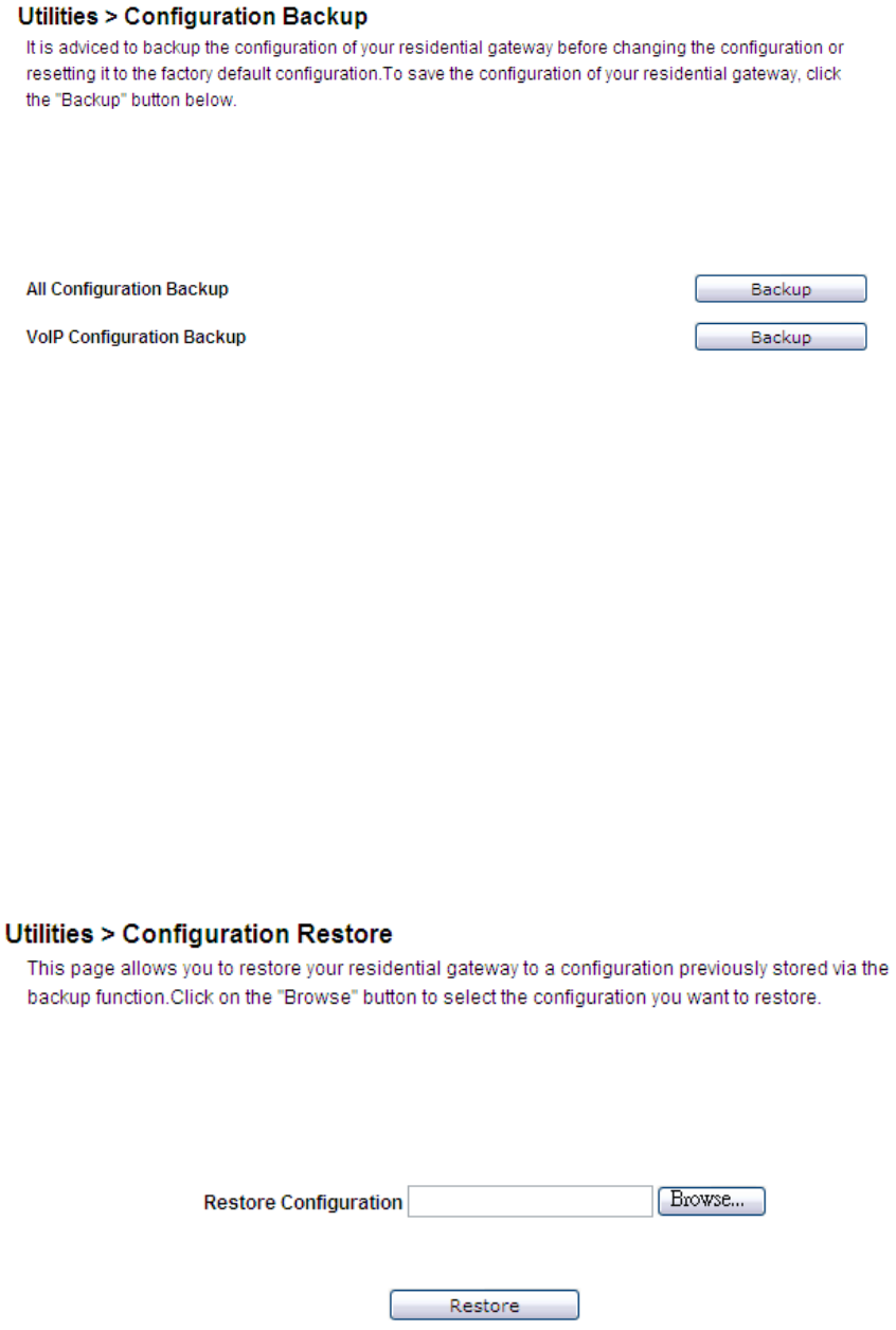
............................................................................................................................................................................................................................................................
Configuration RestoreUtilities
11-2 3EQ-10280-AAAA-TCZZA
Edition 01 February 2011
............................................................................................................................................................................................................................................................
Figure 11-1 Configuration Backup window
Click Backup to save your system configuration.
Configuration Restore
The Configuration Restore window enables you to restore a saved configuration of the
CellPipe 7130 RG from a backup file.
CAUTION
Restoring a stored configuration will overwrite any existing configurations.
Select Configuration Restore in the Utilities menu to access the Configuration Restore
window; see Figure 11-2.
Figure 11-2 Configuration Restore window
Table 11-1 describes the fields of the Configuration Restore window.
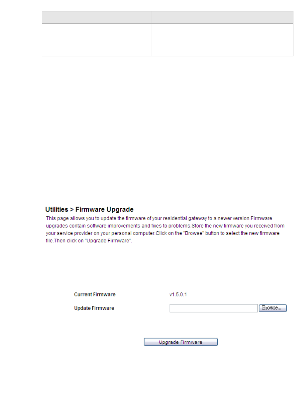
UtilitiesFirmware Upgrade
............................................................................................................................................................................................................................................................
3EQ-10280-AAAA-TCZZA
Edition 01 February 2011 11-3
............................................................................................................................................................................................................................................................
Table 11-1 Field descriptions
Firmware Upgrade
The Firmware Upgrade window enables you to update the firmware of the
CellPipe 7130 RG.
Note: The new firmware file must be downloaded and saved to your computer or a
storage device before uploading.
WARNING
Do not turn off the power or disturb the system during a firmware upgrade.
Select Firmware Upgrade in the Utilities menu to access the Firmware Upgrade window;
see Figure 11-3.
Figure 11-3 Firmware Upgrade window
Table 11-2 describes the fields of the Firmware Upgrade window.
Field Description
Restore Configuration Click Browse and select a configuration backup file
to restore.
Restore Click to restore the configuration.

............................................................................................................................................................................................................................................................
System SettingsUtilities
11-4 3EQ-10280-AAAA-TCZZA
Edition 01 February 2011
............................................................................................................................................................................................................................................................
Table 11-2 Field descriptions
System Settings
The System Settings window enables you to change the web administrator username and
password and configure settings such as the time zone, NTP, and daylight savings.
Note: It is highly recommended that you change the default administrator username
and password and the default Telnet username and password.
Select System Settings in the Utilities menu to access the System Settings window; see
Figure 11-4.
Field Description
Current Firmware The current firmware version.
Update Firmware Click Browse to locate and select the firmware
upgrade file to upload.
New firmware is available from http://www.alcatel-
lucent.com/wps/portal/support.
Note: You must obtain the upgrade file before
uploading.
Upgrade Firmware Click to update the firmware.
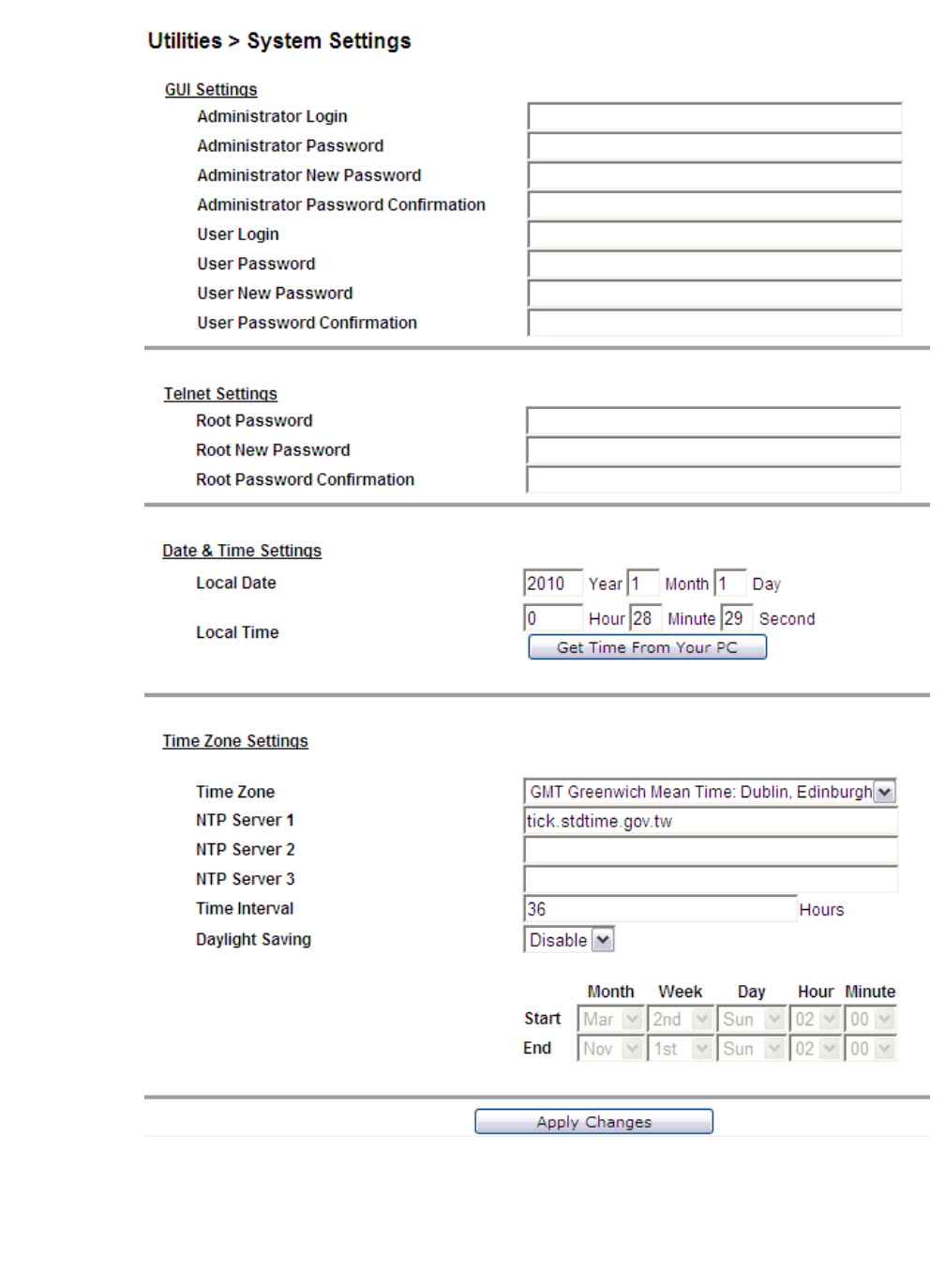
UtilitiesSystem Settings
............................................................................................................................................................................................................................................................
3EQ-10280-AAAA-TCZZA
Edition 01 February 2011 11-5
............................................................................................................................................................................................................................................................
Figure 11-4 System Settings window
Table 11-3 describes the fields of the System Settings window.

............................................................................................................................................................................................................................................................
System SettingsUtilities
11-6 3EQ-10280-AAAA-TCZZA
Edition 01 February 2011
............................................................................................................................................................................................................................................................
Table 11-3 Field descriptions
Field Description
GUI Settings
Administrator Login Enter a new administrator username.
Administrator Password Enter the current administrator password.
Note: If this is the first time the admin password is
being changed, the default admin password is
admin.
Administrator New Password Enter a new administrator password.
Administrator Password Confirmation Retype the new password to confirm.
User Login Enter a new username.
User Password Enter the current user password.
Note: If this is the first time the user password is
changed, the default user password is user.
User New Password Enter a new user password.
User Password Confirmation Retype the new password to confirm.
Telnet Settings
Root Password Enter the current Telnet root password.
Note: If this is the first time the root password is
changed, the default root password is admin.
Root New Password Enter a new Telnet password.
Root Password Confirmation Retype the new password to confirm.
Date & Time Settings
Local Date Displays the current date according to the time zone
configuration.
Local Time Displays the current time according to the time zone
configuration.
Get Time From Your PC Click to set the time according to your PC.
Time Zone Settings
Time Zone Select your time zone.
NTP Server 1 to 3 Enter the IP address or URL of the NTP server.
Time Interval Enter an interval time in hours.
Daylight Saving Select Enable to turn on daylight savings. Select
Disable to turn off daylight savings.
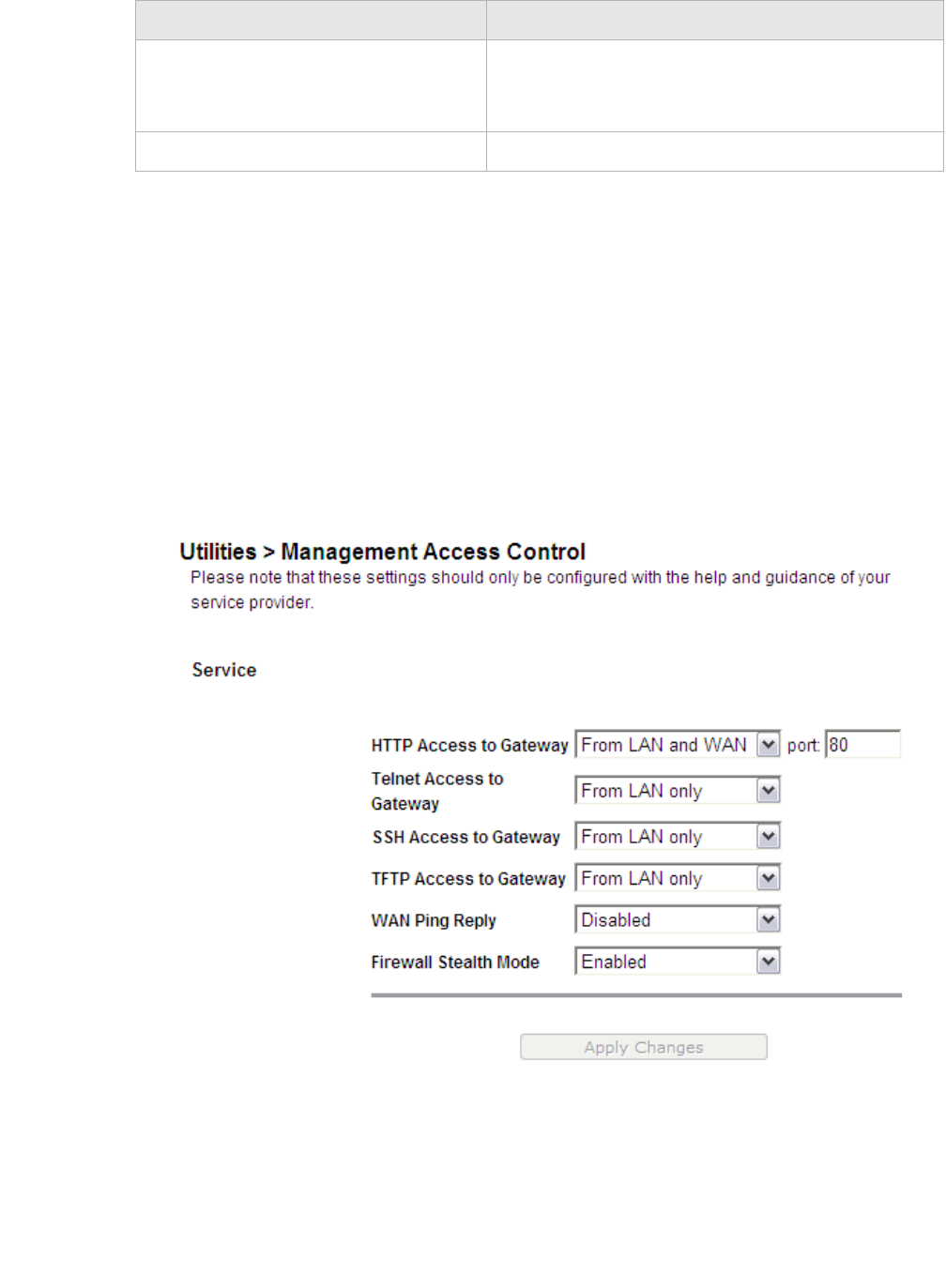
UtilitiesManagement Access Control
............................................................................................................................................................................................................................................................
3EQ-10280-AAAA-TCZZA
Edition 01 February 2011 11-7
............................................................................................................................................................................................................................................................
Management Access Control
The Management Access Control window enables you to control who can access the
service provided by the gateway.
Note: It is recommended that you consult your ISP before configuring access.
Select Management Access in the Utilities menu to access the Management Access
Control window; see Figure 11-5.
Figure 11-5 Management Access Control window
Table 11-4 describes the fields of the Management Access Control window.
Start/End If you have enabled daylight savings, select the
Month, Week, Day, Hour, and Minute for the
daylight savings to start and end.
Apply Changes Click to save your changes.
Field Description

............................................................................................................................................................................................................................................................
CWMP ManagementUtilities
11-8 3EQ-10280-AAAA-TCZZA
Edition 01 February 2011
............................................................................................................................................................................................................................................................
Table 11-4 Field descriptions
CWMP Management
The CWMP Management window enables you to configure remote access of the
CellPipe 7130 RG.
Select CWMP Management in the Utilities menu to access the CWMP Management
window; see Figure 11-6.
Field Description
HTTP Access to Gateway
Telnet Access to Gateway
SSH Access to Gateway
TFTP Access to Gateway
Select one of the following settings:
•Disable
•From LAN only
•From WAN only
•From LAN and WAN
WAN Ping Reply Select Enable to allow the WAN interface to
respond to the echo request from the default WAN
connection. Select Disable to deny the WAN
interface from responding to the echo request from
the default WAN connection.
Firewall Stealth Mode Select Enable to allow firewall to drop all stealth or
unknown traffic. Select Disable to accept all
unknown traffic.
Apply Changes Click to save your changes.
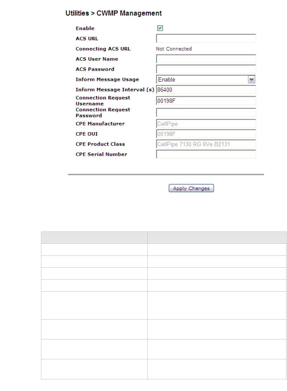
UtilitiesCWMP Management
............................................................................................................................................................................................................................................................
3EQ-10280-AAAA-TCZZA
Edition 01 February 2011 11-9
............................................................................................................................................................................................................................................................
Figure 11-6 CWMP Management window
Table 11-5 describes the fields of the CWMP Management window.
Table 11-5 Field descriptions
Field Description
Enable Check this box to Enable CWMP management.
ACS URL Enter the URL of the ACS.
ACS User Name Enter the username of the ACS.
ACS Password Enter the password for the ACS.
Inform Message Usage Select Enable to have the device information sent to
the ACS. Select Disable to not have the information
sent to the ACS.
Inform Message Interval (s) Enter an interval in seconds for sending inform
messages.
Connection Request Username Enter the username used to authenticate an ACS
making a connection request to the device.
Connection Request Password Enter the password for the connection request of the
ACS to the device.
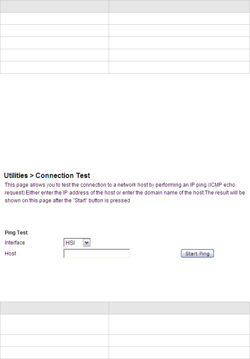
............................................................................................................................................................................................................................................................
Connection TestUtilities
11-10 3EQ-10280-AAAA-TCZZA
Edition 01 February 2011
............................................................................................................................................................................................................................................................
Connection Test
The Connection Test window enables you to test the connectivity with other network
devices.
Select Connection Test in the Utilities menu to access the Connection Test window; see
Figure 11-7.
Figure 11-7 Connection Test window
Table 11-6 describes the fields of the Connection Test window.
Table 11-6 Field descriptions
CPE Manufacturer (read-only) The manufacturer of the device.
CPE OUI (read-only) The OUI of the device.
CPE Product Class (read-only) The model of the device.
CPE Serial Number (read-only) The serial number of the device.
Apply Changes Click to save your changes.
Field Description
Field Description
Interface Select an interface to test if the connection is
functioning.
Host Enter a host IP address to test the connection.
Start Click to test the connection.
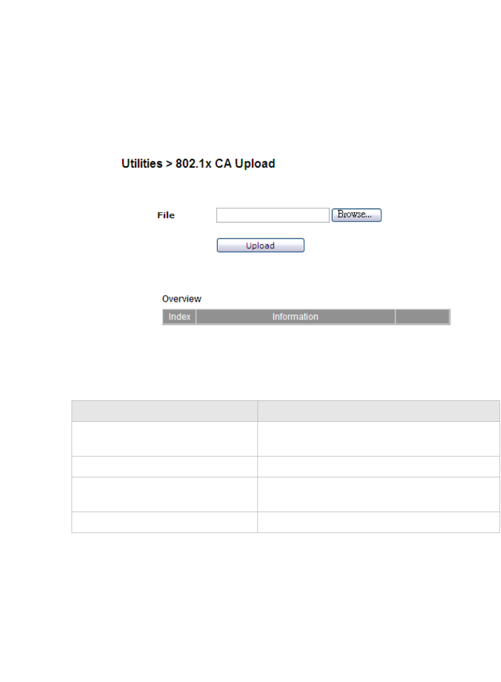
Utilities802.1x CA Upload
............................................................................................................................................................................................................................................................
3EQ-10280-AAAA-TCZZA
Edition 01 February 2011 11-11
............................................................................................................................................................................................................................................................
802.1x CA Upload
The 802.1x CA upload window enables you to upload an 802.1x CA certificate. If you
have configured a DHCP WAN connection with 802.1x enabled, then you can use this
window to upload a CA that is used to authenticate you with your ISP to be granted DHCP
service.
Select 802.1x CA Upload in the Utilities menu to access the 802.1x CA Upload window;
see Figure 11-8.
Figure 11-8 802.1x CA Upload window
Table 11-7 describes the fields of the 802.1x CA Upload window.
Table 11-7 Field descriptions
Restore Factory Defaults
The Restore Factory Defaults window enables you to restore the default settings of the
CellPipe 7130 RG.
Field Description
File Click Browse to select a CA certificate on your
computer to upload.
Upload Click to upload the selected CA certificate.
Index The index number of the CA certificate. A
maximum of eight CA certificates are supported.
Information The information pertaining to the CA certificate.
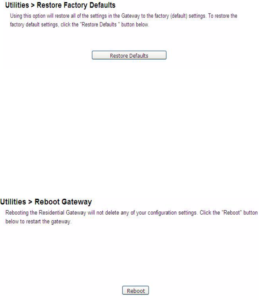
............................................................................................................................................................................................................................................................
Reboot GatewayUtilities
11-12 3EQ-10280-AAAA-TCZZA
Edition 01 February 2011
............................................................................................................................................................................................................................................................
CAUTION
Restoring the factory default settings will replace your current configuration.
Router IP or password changes will also be reset to the default.
Select Restore Factory Defaults in the Utilities menu to access the Restore Factory
Defaults window; see Figure 11-9.
Figure 11-9 Restore Factory Defaults window
Click Restore Defaults to restore the CellPipe 7130 RG to the factory default settings.
Reboot Gateway
The Reboot Gateway window enables you to reboot the CellPipe 7130 RG.
Note: Rebooting the gateway does not reset your settings.
Select Reboot Gateway in the Utilities menu to access the Reboot Gateway window; see
Figure 11-10.
Figure 11-10 Reboot Gateway window
Click Reboot to restart the CellPipe 7130 RG.
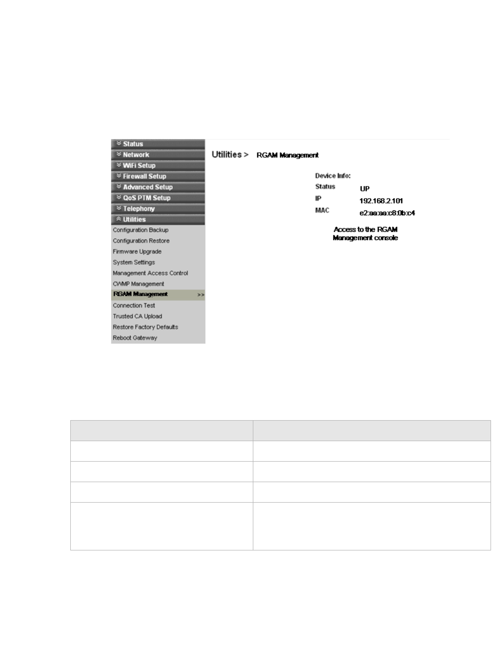
UtilitiesRGAM Management
............................................................................................................................................................................................................................................................
3EQ-10280-AAAA-TCZZA
Edition 01 February 2011 11-13
............................................................................................................................................................................................................................................................
RGAM Management
Please click on Utilities which unfolds the sub-menu. This will show the status of the
RGAM. By clicking on the "Access to the RGAM Management interface", the RGAM
interface pops up in a different window.
Select RGAM Management in the Utilities menu to access the RGAM Management
window; see Figure 11-11.
Figure 11-11 RGAM Management window
Table 11-8 describes the fields of the RGAM Management window.
Table 11-8 Field descriptions
Field Description
Status Gives the status if the RGAM is connected
IP IP address which is assigned to the RGAM
MAC MAC address which is used by the RGAM
"Access to the RGAM management console" opens
an new windows which is connected to the web
console of the RGAM
............................................................................................................................................................................................................................................................
RGAM ManagementUtilities
11-14 3EQ-10280-AAAA-TCZZA
Edition 01 February 2011
............................................................................................................................................................................................................................................................

A-1
3EQ-10280-AAAA-TCZZA
Edition 01 February 2011
............................................................................................................................................................................................................................................................
A Troubleshooting
Overview
This section identifies common problems that can arise during the use of the
CellPipe 7130 RG and offers solutions. Most issues are identified by the LEDs on the
front panel of the CellPipe 7130 RG.
Troubleshooting Table
Symptom Possible cause Solution
Power LED does not
come on after power is
switched on.
Outlet, power cord, or power
adapter might be defective.
•Check the outlet by
plugging in another
electronic device.
•Call the customer service
number or return the device
to the vendor.
VDSL Link LED
flashes slowly after
connection is
established then it
quickly stats to flash
slowly again.
The DSL port on the gateway or
the cable might be defective. •Switch the power off and
then switch the power on.
•Verify that the cable is
connected properly to the
VDSL wall line and the
DSL connector on the
CellPipe 7130 RG.
LAN LED does not
come on after
connection is
established.
The LAN port on the CellPipe
7130 RG, the network interface
on the computer, or a network
cable may be defective or not
connected.
•Verify that the power of
CellPipe 7130 RG and
computer are switched on.
•Ensure that the cable is
plugged into the CellPipe
7130 RG and the device.
•Check the network adapter
or the cable connections for
defects.

............................................................................................................................................................................................................................................................
OverviewTroubleshooting
A-2 3EQ-10280-AAAA-TCZZA
Edition 01 February 2011
............................................................................................................................................................................................................................................................
Message LED is
flashing.
A firmware upgrade is in
progress.
•Verify that a firmware
upgrade is in progress.
•Wait until the firmware
upgrade is finished.
Intenet LED is off. Your CellPipe 7130 RG is
unable to connect to the Internet
or CellPipe 7130 RG is not
power on.
•Verify that your CellPipe
7130 RG has configured
WAN connections properly.
•Verify that the power is
switched on.
Symptom Possible cause Solution

B-1
3EQ-10280-AAAA-TCZZA
Edition 01 February 2011
............................................................................................................................................................................................................................................................
B TCP/IP configuration
Overview
The following procedures provide TCP/IP configuration instructions for all supported
operating systems.
Windows 7
1. Open Network and Internet from the Control Panel.
2. Open Network and Sharing Center from the Network and Internet.
3. Right-click Local Area Connection from Network and Sharing Center.
4. Under the General tab, select Internet Protocol (TCP/IPv4), and click Properties.
5. Select the Obtain an IP address automatically radio button.
6. Select the Obtain DNS server address automatically radio button.
7. Click OK to save the settings.
........................................................................................................................................................
END OF STEPS
Windows Vista
1. Open Network and sharing Center from the Control Panel.
2. Open Manage network connections from the Network and sharing Center.
3. Right-click Ethernet connection and select Properties.
4. Under the General tab, select Internet Protocol (TCP/IPv4), and click Properties.
5. Select the Obtain an IP address automatically radio button.
6. Select the Obtain DNS server address automatically radio button.
7. Click OK to save the settings.
........................................................................................................................................................
END OF STEPS
Windows XP
1. Open Network Connections from the Control Panel.
2. Right-click Ethernet connection and select Properties.

............................................................................................................................................................................................................................................................
OverviewTCP/IP configuration
B-2 3EQ-10280-AAAA-TCZZA
Edition 01 February 2011
............................................................................................................................................................................................................................................................
3. Under the General tab, select Internet Protocol (TCP/IP), and click Properties. The
Internet Protocol (TCP/IP) properties window appears.
4. Select the Obtain an IP address automatically radio button.
5. Select the Obtain DNS server address automatically radio button.
6. Click OK to save the settings.
........................................................................................................................................................
END OF STEPS
Windows Me/2000/98/95
1. Open Network and Dialing Connections from the Control Panel.
2. Right click the Ethernet connection icon and select Properties.
3. Select Internet Protocol (TCP/IP) component, and click Properties. The Internet
Protocol (TCP/IP) properties window appears.
4. Select the Obtain an IP address automatically radio button.
5. Select the Obtain DNS server address automatically radio button.
6. Click OK to save the settings.
........................................................................................................................................................
END OF STEPS
Windows NT
1. Open Network from the Control Panel.
2. From the Protocol tab, select the Internet Protocol (TCP/IP) component, and click
the Properties button.
3. From the IP Address tab, select the Obtain an IP address automatically radio button.
4. From the DNS tab, verify that no DNS server is defined in the DNS Service Search
Order box and no suffix is defined in the Domain Suffix Search Order box.
........................................................................................................................................................
END OF STEPS
Mac OS
1. Open System Preferences from the Panel.
2. Choose Network from Internet & Network.
3. Make sure the window is unlocked. If it is locked, click the lock to make changes and
enter the password for authentication.
4. From the TCP/IP tab, choose the Using DHCP on Configure IPv4 field.
5. Click on the Apply Now button to obtain an IP address from the DHCP server.
........................................................................................................................................................
END OF STEPS

C-1
3EQ-10280-AAAA-TCZZA
Edition 01 February 2011
............................................................................................................................................................................................................................................................
C Product conformance
Overview
This section lists the product conformance requirements for the EU and the FCC
conformance requirements.
EU declaration of conformity
This device complies with the essential requirements of the R&TTE Directive 1999/5/EC.
The following test methods have been applied in order to prove presumption of
conformity with the essential requirements of the R&TTE Directive 1999/5/EC:
•IEC 60950-1: 2006 + A11: 2009
Safety of Information Technology Equipment
•EN50385 : (2002-08)
Product standard to demonstrate the compliance of radio base stations and fixed
terminal stations for wireless telecommunication systems with the basic restrictions or
the reference levels related to human exposure to radio frequency electromagnetic
fields (110MHz - 40 GHz) - General public
•EN 300 328 V1.7.1: (2006-10)
Electromagnetic compatibility and Radio spectrum Matters (ERM); Wideband
Transmission systems; Data transmission equipment operating in the 2,4 GHz ISM
band and using spread spectrum modulation techniques; Harmonized EN covering
essential requirements under article 3.2 of the R&TTE Directive
•EN 301 489-1 V1.8.1: (2008-04)
Electromagnetic compatibility and Radio Spectrum Matters (ERM); ElectroMagnetic
Compatibility (EMC) standard for radio equipment and services; Part 1: Common
technical requirements
•EN 301 489-17 V2.1.1 (2009-05)
Electromagnetic compatibility and Radio spectrum Matters (ERM); ElectroMagnetic
Compatibility (EMC) standard for radio equipment; Part 17: Specific conditions for
Broadband Data Transmission Systems

............................................................................................................................................................................................................................................................
EU declaration of conformityProduct conformance
C-2 3EQ-10280-AAAA-TCZZA
Edition 01 February 2011
............................................................................................................................................................................................................................................................
This device is a 2.4 GHz wideband transmission system (transceiver), intended for use in
all EU member states and EFTA countries, except in France and Italy where restrictive use
applies.
In Italy the end-user should apply for a license at the national spectrum authorities in order
to obtain authorization to use the device for setting up outdoor radio links and/or for
supplying public access to telecommunications and/or network services.
This device may not be used for setting up outdoor radio links in France and in some areas
the RF output power may be limited to 10 mW EIRP in the frequency range of 2454 –
2483.5 MHz. For detailed information the end-user should contact the national spectrum
authority in France.

Product conformanceFCC 15B statement
............................................................................................................................................................................................................................................................
3EQ-10280-AAAA-TCZZA
Edition 01 February 2011 C-3
............................................................................................................................................................................................................................................................
FCC 15B statement
Federal Communication Commission Interference Statement
This equipment has been tested and found to comply with the limits for a Class B
digital device, pursuant to Part 15 of the FCC Rules. These limits are designed to provide
reasonable protection against harmful interference in a residential installation. This
equipment generates, uses and can radiate radio frequency energy and, if not installed and
used in accordance with the instructions, may cause harmful interference to radio
communications. However, there is no guarantee that interference will not occur in a
particular installation. If this equipment does cause harmful interference to radio or
television reception, which can be determined by turning the equipment off and on, the
user is encouraged to try to correct the interference by one of the following measures:
•Reorient or relocate the receiving antenna.
•Increase the separation between the equipment and receiver.
•Connect the equipment into an outlet on a circuit different from that to which the
receiver is connected.
•Consult the dealer or an experienced radio/TV technician for help.
FCC Caution: Any changes or modifications not expressly approved by the party
responsible for compliance could void the user's authority to operate this equipment.
This device complies with Part 15 of the FCC Rules. Operation is subject to the
following two conditions: (1) This device may not cause harmful interference, and (2) this
device must accept any interference received, including interference that may cause
undesired operation.
IMPORTANT NOTE:
FCC Radiation Exposure Statement
This equipment complies with FCC radiation exposure limits set forth for an
uncontrolled environment. This equipment should be installed and operated with
minimum distance 20cm between the radiator & your body.
This transmitter must not be co-located or operating in conjunction with any other
antenna or transmitter.
The availability of some specific channels and/or operational frequency bands are
country dependent and are firmware programmed at the factory to match the intended
destination. The firmware setting is not accessible by the end user.
............................................................................................................................................................................................................................................................
FCC Part 68 StatementProduct conformance
C-4 3EQ-10280-AAAA-TCZZA
Edition 01 February 2011
............................................................................................................................................................................................................................................................
FCC Part 68 Statement
This equipment complies with Part 68 of the FCC rules and the requirements adopted by
the ACTA. On the base unit of this equipment is a label that contains, among other
information, a product identifier in the format US: GEMDL01BWVVDB101N. If
requested, this number must be provided to the telephone company.
Applicable connector jack Universal Service Order Codes ("USOC") for the Equipment is
RJ11C and RJ45.
A plug and jack used to connect this equipment to the premises wiring and telephone
network must comply with the applicable FCC Part 68 rules and requirements adopted by
the ACTA. A compliant telephone cord and modular plug is provided with this product. It
is designed to be connected to a compatible modular jack that is also compliant. See
installation instructions for details.
The REN is used to determine the number of devices that may be connected to a telephone
line. Excessive RENs on a telephone line may result in the devices not ringing in response
to an incoming call. In most but not all areas, the sum of RENs should not exceed five
(5.0). To be certain of the number of devices that may be connected to a line, as
determined by the total RENs, contact the local telephone company. For products
approved after July 23, 2001, the REN for this product is part of the product identifier that
has the format US: GEMDL01BWVVDB101N. The digits represented by 01 are the REN
without a decimal point (e.g., 03 is a REN of 0.3).
If this CellPipe 7130 RG 6Vz.A2131 causes harm to the telephone network, the telephone
company will notify you in advance that temporary discontinuance of service may be
required. But if advance notice isn't practical, the telephone company will notify the
customer as soon as possible. Also, you will be advised of your right to file a complaint
with the FCC if you believe it is necessary.
The telephone company may make changes in its facilities, equipment, operations or
procedures that could affect the operation of the equipment. If this happens the telephone
company will provide advance notice in order for you to make necessary modifications to
maintain uninterrupted service.
If trouble is experienced with this Alcatel-Lucent, for repair or warranty information,
please contact 600-700 Mountain Avenue Murry Hill, NJ 07974 or Tel no.: 1-908-508-
8080 If the equipment is causing harm to the telephone network, the telephone company
may request that you disconnect the equipment until the problem is resolved.

Product conformanceIndustry Canada statement
............................................................................................................................................................................................................................................................
3EQ-10280-AAAA-TCZZA
Edition 01 February 2011 C-5
............................................................................................................................................................................................................................................................
Connection to party line service is subject to state tariffs. Contact the state public utility
commission, public service commission or corporation commission for information.
If your home has specially wired alarm equipment connected to the telephone line, ensure
the installation of this equipment does not disable your alarm equipment. If you have
questions about what will disable alarm equipment, consult your telephone company or a
qualified installer.
WHEN PROGRAMMING EMERGENCY NUMBERS AND(OR) MAKING TEST
CALLS TO EMERGENCY NUMBERS:
1) Remain on the line and briefly explain to the dispatcher the reason for the call.
2) Perform such activities in the off-peak hours, such as early morning or late evenings.
Industry Canada statement
This device complies with RSS-210 of the Industry Canada Rules. Operation is
subject to the following two conditions: (1) This device may not cause harmful
interference, and (2) this device must accept any interference received, including
interference that may cause undesired operation.
IMPORTANT NOTE:
Radiation Exposure Statement
This equipment complies with Canada radiation exposure limits set forth for an
uncontrolled environment. This equipment should be installed and operated with
minimum distance 20cm between the radiator & your body.
............................................................................................................................................................................................................................................................
IC TELECOMProduct conformance
C-6 3EQ-10280-AAAA-TCZZA
Edition 01 February 2011
............................................................................................................................................................................................................................................................
This transmitter must not be co-located or operating in conjunction with any other
antenna or transmitter.
IC TELECOM
''NOTICE: This equipment meets the applicable Industry Canada Terminal
Equipment Technical Specifications. This is confirmed by the registration number. The
abbreviation, IC, before the registration number signifies that registration was performed
based on a Declaration of Conformity indicating that Industry Canada technical
specifications were met. It does not imply that Industry Canada approved the equipment."
''NOTICE: The Ringer Equivalence Number (REN) for this terminal equipment is
01. The REN assigned to each terminal equipment provides an indication of the maximum
number of terminals allowed to be connected to a telephone interface. The termination on
an interface may consist of any combination of devices subject only to the requirement
that the sum of the Ringer Equivalence Numbers of all the devices does not exceed five.''
"CAUTION: To reduce the risk of fire, use only No. 26 AWG or larger (e.g., 24 AWG) UL
Listed or CSA Certified Telecommunication Line Cord"

Product conformanceIC TELECOM
............................................................................................................................................................................................................................................................
3EQ-10280-AAAA-TCZZA
Edition 01 February 2011 C-7
............................................................................................................................................................................................................................................................
"IMPORTANT SAFETY INSTRUCTIONS - When using your telephone equipment,
basic safety precautions should always be followed to reduce the risk of fire, electric
shock and injury to persons, including the following:
•Do not use this product near water for example, near a bathtub, washbowl, kitchen
sink or laundry tub, in a wet basement or near a swimming pool.
•Avoid using a telephone (other than a cordless type) during an electrical storm. There
may be a remote risk of electric shock from lightning.
•Do not use the telephone to report a gas leak in the vicinity of the leak.
•Use only the power cord and batteries indicated in this manual. Do not dispose of
batteries in a fire. They may explode. Check with local codes for possible special
disposal instructions.
SAVE THESE INSTRUCTIONS"
............................................................................................................................................................................................................................................................
IC TELECOMProduct conformance
C-8 3EQ-10280-AAAA-TCZZA
Edition 01 February 2011
............................................................................................................................................................................................................................................................

GL-1
3EQ-10280-AAAA-TCZZA
Edition 01 February 2011
............................................................................................................................................................................................................................................................
Glossary
Numerics
10/100Base-T
The most widely used standard for Ethernet over twisted pair or copper-based
computer networking. Runs at 10 Mb/s, 100 Mb/s, and 1000 Mb/s (1 Gb/s)
respectively.
802.11b/g/n
A family of specifications for wireless local area networks (WLANs). They use the
Ethernet protocol and CSMA/CA (carrier sense multiple access with collision
avoidance) for path sharing.
802.1 Q/P
The standard that allows multiple bridged networks to transparently share the same
physical network link without leakage of information between networks.
802.1x
An authentication standard for clients connecting to an IEEE 802 network such as
Ethernet (access) networks and 802.11 (public) wireless LANs.
A
ACS
Auto-Configuration Server
ALG
Application-Level Gateway
AP
Access Point
API
Application Programming Interface
C
CDVT
Cell Delay Variation Tolerance
CHAP
Challenge-Handshake Authentication Protocol
Codec
A device or computer program capable of encoding and/or decoding a digital data
stream or signal.
CoS
Class of Service
............................................................................................................................................................................................................................................................
Glossary
GL-2 3EQ-10280-AAAA-TCZZA
Edition 01 February 2011
............................................................................................................................................................................................................................................................
CPE
Customer Premises Equipment
CWMP
CPE WAN Management Protocol
D
DDNS
Dynamic Domain Name System
DHCP
Dynamic Host Configuration Protocol
DMZ
Demilitarized Zone
DNS
Domain Name System
DSCP
Differentiated Services Code Point
DSL
Digital Subscriber Line
DTIM
Delivery Traffic Indication Message
Dynamic Routing
The capability of a system, through which routes are characterised by their destination,
to alter the path that the route takes through the system in response to a change in
conditions.
E
Ethernet
A family of frame-based computer networking technologies for local area networks
(LANs).
F
Firewall
An integrated collection of security measures designed to prevent unauthorized
electronic access to a networked computer system.
FQDN
FullQualified Domain Name
FTN
Forward to Number
G
Gateway
A network node equipped for interfacing with another network that uses different
protocols.

Glossary
GL-3
3EQ-10280-AAAA-TCZZA
Edition 01 February 2011
............................................................................................................................................................................................................................................................
............................................................................................................................................................................................................................................................
H
HTML
Hyper Text Markup Language
I
IGMP
Internet Group Management Protocol
IP
Internet Protocol
IPSec
Internet Protocol Security
ISP
Internet Service Provider
K
kb/s
Kilobit per second; a data rate unit.
L
L2TP
Layer 2 tunneling protocol; a tunneling protocol used to support virtual private
networks (VPNs).
LAN
Local Area Network
M
MAC
Media Access Control
Mb
Megabit; a unit of information commonly used to express the rate data is transferred.
MTU
Maximum Transmission Unit
N
NAT
Network Address Translation
Netmask
The designated IP address routing prefix for a network of computers and devices.
NIC
Network Interface Controller
NTP
Network Time Protocol
............................................................................................................................................................................................................................................................
Glossary
GL-4 3EQ-10280-AAAA-TCZZA
Edition 01 February 2011
............................................................................................................................................................................................................................................................
O
OUI
Organizationally Unique Identifier
Outbound Proxy Server
The server responsible for handling calls made behind the NAT device by examining
and translating the IP addresses.
P
PAP
Password Authentication Protocol
Ping
A computer network tool used to test whether a particular host is reachable across an
IP network.
PPPoE
Point-to-Point Protocol over Ethernet
PPTP
Point-to-Point Tunneling Protocol
PSK
Pre-Shared Key
Q
QoS
Quality of Service
R
RJ-11
A physical interface often used for terminating telephone wires.
RJ-45
Most regularly used as an Ethernet connector. RJ-45 connectors are typically used to
terminate twisted pair cable.
RTP
Real-time Transport Protocol; handles voice data transfer making VoIP call using SIP.
S
SSH
Secure Shell
SIP
Session Initiation Protocol; an application layer control protocol that handles the
setting up, altering and tearing down of voice and multimedia sessions over the
Internet.
SSID
Service Set Identifier

Glossary
GL-5
3EQ-10280-AAAA-TCZZA
Edition 01 February 2011
............................................................................................................................................................................................................................................................
............................................................................................................................................................................................................................................................
Subnet
See Netmask.
T
TCP
Transmission Control Protocol
Tel ne t
Telecommunications network; a network protocol used on the Internet or local area
network (LAN) connections.
TFTP
Trivial File Transfer Protocol
To S
Type of Service
U
UDP
User Datagram Protocol
UPnP
Universal Plug and Play
URL
Uniform Resource Locator
V
VCI
Virtual Channel Identifier
VDSL
Very High Bitrate Digital Subscriber Line
VLAN
Virtual Local Area Network
VoIP
Voice over Internet Protocol
VPI
Virtual Path Identifier
W
WAN
Wide Area Network
WDS
Wireless Distribution System
WEP
Wired Equivalent Privacy
............................................................................................................................................................................................................................................................
Glossary
GL-6 3EQ-10280-AAAA-TCZZA
Edition 01 February 2011
............................................................................................................................................................................................................................................................
WiFi
Wireless networking compatibility
WLAN
Wireless Local Area Network
WPA
WiFi Protected Access
WPS
WiFi Protected Setup