GemTek Technology WX1520 WLAN Access Point User Manual Managing Access Points with APCenter
Gemtek Technology Co., Ltd. WLAN Access Point Managing Access Points with APCenter
manual
Version 1.2 – June 2000
Important Notice
This device is a 2.4 GHz low power Wireless Access Point transceiver
intended for use in all EU memberstates, except for France where
restrictive use applies.
Please refer to page 4 of this manual for further details.

Version 1.1 – June 2000
Copyright statement
No part of this publication may be reproduced, stored in a retrieval system, or transmitted in any form or by any means, whether
electronic, mechanical, photocopying, recording, or otherwise without the prior writing of the publisher.
Printed in Taiwan, June 2000

FCC Radiation Exposure Statement
This equipment complies with FCC radiation exposure limits set forth for an uncontrolled environment. This equipment should
be installed and operated with the minimum distance between your body and the antenna as shown in the table below:
Low gain indoor antennas (6dBi) 4.5cm (1.8 inches)
Note: Detached antennas, whether installed indoors or out, should be installed ONLY by experienced antenna installation professionals who
are familiar with local building and safety codes and, wherever applicable, are licensed by the appropriate government regulatory authorities.
R&TTE Compliance Statement
This equipment complies with all the requirements of the DIRECTIVE 1999/5/EC OF THE EUROPEAN PARLIAMENT AND
THE COUNCIL of 9 March 1999 on radio equipment and telecommunication terminal Equipment and the mutual recognition of
their conformity (R&TTE).
The R&TTE Directive repeals and replaces in the directive 98/13/EEC (Telecommunications Terminal Equipment and Satellite
Earth Station Equipment) As of April 8, 2000.
Safety
This equipment is designed with the utmost care for the safety of those who install and use it. However, special attention must
be paid to the dangers of electric shock and static electricity when working with electrical equipment. All guidelines of this
manual and of the computer manufacturer must therefore be allowed at all times to ensure the safe use of the equipment.
EU Countries intended for use
The ETSI version of this device is intended for home and office use in Austria, Belgium, Denmark, Finland, France (with
Frequency channel restrictions), Germany, Greece, Ireland, Italy, Luxembourg, The Netherlands, Portugal, Spain, Sweden and
United Kingdom.
The ETSI version of this device is also authorized for use in EFTA member states Iceland, Liechtenstein, Norway and
Switzerland.
EU Countries Not intended for use
None.
Potential restrictive use
France: Only channels 10,11,12, and13

We, the undersigned,
Company GEMTEK Technology Co., Ltd.
Address, City No.1, Jen Ai Road, Hsinchu Industrial Park Hukuo Hsiang, Hsinchu Hsien
Country Taiwan, R.O.C
Phone number 886-3-598-5535 x1030
Fax number 886-3-598-5585
certify and declare under our sole responsibility that the following equipment:
Product description / Intended use 2.4 GHz Low Power RLAN Access Point transceiver
EU /EFTA memberstates intended for use EU: Austria, Belgium, Denmark, Finland, France, Germany Greece,
Ireland, Italy, Luxembourg, the Netherlands, Portugal, Spain,
Sweden, United Kingdom
EFTA: Switzerland, Iceland, Lichtenstein, Norway
Restrictive use France (operating band restricted to 2446.5-2483.5MHz)
Manufacturer GEMTEKk Technology Co., Ltd.
Brand GEMTEK
Type WX1500 and WX1520
is tested to and conforms with the essential radio test suites included in following standards:
Standard Issue date
ETS 300 328
ETS 300 826
EN 60950
Ed.2, Nov.1996
Ed.1, Nov. 1997
(1992), incl. A1(1993), A2(1993),A3(1995), A4(1997)
and therefore complies with the essential requirements and provisions of the Directive 1999/5/EC of the
European Parliament and of the council of 9 march 1999 on Radio equipment and Telecommunications Terminal
Equipment and the mutual recognition of their conformity and Annex IV (Conformity Assessment procedure
referred to in article 10(4)).
The following Notified Bodies have been consulted in the Conformity Assessment procedure:
Notified Body number Name and address
0122 NMi Certin B.V., POB 15, 9822 ZG Niekerk, The Netherlands
The technical documentation as required by the Conformity Assessment procedure is kept at the following address:
Company NoWiresNeeded B.V.
Address, City Rembrandtlaan 1a, Bilthoven
Country The Netherlands
Phone number +31 30 2296060
Fax number +31 30 2296061
Drawn up in Hsinchu Hsien, Taiwan R.O.C.
Date 1 June 2000
Name and position Mike Chen, Vice President, GemTek Technology Co., Ltd.
GemTek Technology Co., Ltd.
1 Contents
1 Contents................................................................................................................................................................................... 6
2 Introduction .............................................................................................................................................................................. 7
3 Installation ................................................................................................................................................................................ 8
4 APManager™ Features ........................................................................................................................................................... 9
4.1 APManager™ Main Window .......................................................................................................................................... 10
4.2 Quick Start to Wireless Networking................................................................................................................................ 11
4.3 Managing WLANs .......................................................................................................................................................... 11
4.4 Managing Access Points................................................................................................................................................ 12
4.4.1 Network Settings Dialog......................................................................................................................................... 14
4.4.2 Searching for Access Points .................................................................................................................................. 14
4.4.3 Manually programming IP addresses .................................................................................................................... 15
4.5 Managing Security ......................................................................................................................................................... 16
4.5.1 Access Control ....................................................................................................................................................... 17
4.6 Updating Access Point Settings..................................................................................................................................... 18
4.7 IEEE 802.11 WEP Security............................................................................................................................................ 19
4.8 More about Cells ............................................................................................................................................................ 19
4.9 Compatibility................................................................................................................................................................... 20
5 Glossary ................................................................................................................................................................................. 21
6 Technical specifications of WX-1500 / 1520 .......................................................................................................................... 22
6.1 Standards supported...................................................................................................................................................... 22
6.2 Environmental ................................................................................................................................................................ 22
6.3 Power specifications ...................................................................................................................................................... 22
6.4 Radio specifications ....................................................................................................................................................... 22
6.5 Specific features............................................................................................................................................................. 22
6.6 Physical Dimensions ...................................................................................................................................................... 22
2 Introduction
Thank you for purchasing your WX-1500 / 1520 Wireless LAN Access Point. This manual will assist you with the installation
procedure.
The package you have received should contain the following items:
User manual
WX-1500 / 1520 Access Point
Power adapter
Diskette containing APManager Software
Note: if anything is missing, please contact your vendor
A wireless LAN is normally used in a predefined environment. In such a network, Access Points are mounted at assigned
places, each covering its own area in which wireless nodes can operate. These Access Points are connected to a wired network
to communicate with each other and with servers and clients on that network.
The WX-1500SB Access Point can be connected to a 10 Mbps Ethernet network through a RJ45 (UTP) connector.
3 Installation
1. Mount the Access Point firmly to the wall on the position that is determined during the site survey. A drill model is supplied
as a separate sheet with this manual.
2. Make sure the antennas are in a vertical position (if not, rotate over 90 degrees).
3. Insert the power connector.
4. Attach the UTP Ethernet cable to the Access Point.
5. Switch on the Access Point.
At the front of the Access Point you will see three LEDs.
If all goes well, the middle LED (power) is green and the leftmost (WLAN) and rightmost (wired network) LEDs flash whenever
there is traffic on the respective networks which is at least ten times per second for the wireless LAN because of so-called
‘beacons’.
The Access Point automatically selects the medium attached. When the cable network is detected, the network LED will turn
yellow.
You can reset the Access Point’s settings to factory defaults by pushing a paperclip in the little hole next to the power switch.
The sequence of the ACT is on, and holding until the LED being off.
When you push a paperclip in the reset hole while the Access Point is switched on, only the lock set by APManager™ (Par 4.5)
is deactivated.
4 APManager™ Features
APManager™ provides a consistent view of the Wireless network. The systems administrator can use APManager™ to control
a large number of WX-1500 / 1520 Access Points from a single location. The Access Points are remotely updated via the SNMP
(Simple Network Management Protocol).
Among the supported features are:
Adding and removing Access Points
Restricting access to the Wireless network
Managing data protection options such as IEEE 802.11 WEP
Assigning radio channels for optimal cell management
Grouping the wireless network into multiple WLANs with individual access control and security options
Programming an Access Point with a specified IP address
Setting the SNMP Write Community string
Storing the Access Point configurations on disk
Verifying the status of all Access Points in the network
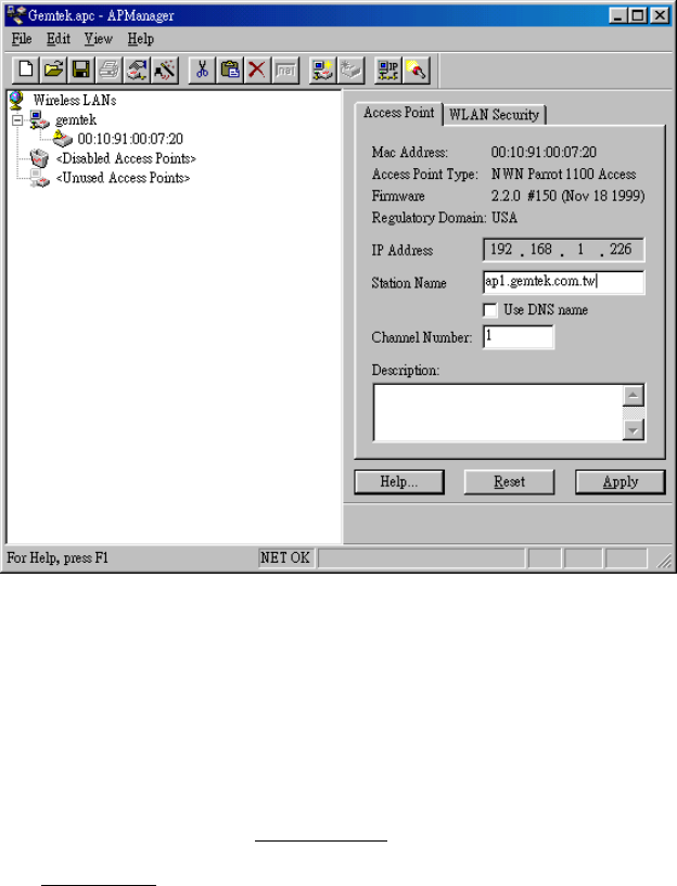
4.1 APManager™ Main Window
The Main Window of APManager™ may look like this. Before going into detail it is good to have an idea of what kind of
information to expect.
You may wish to skip to Quick Start to Wireless Networking.
The tree structure on the left of the window shows a list of WLANs (Wireless LANs) and the Access Points that are part of each
WLAN. The sample image above shows a single Access Point with hardware address 00:10:91:00:07:20 that is assigned to the
WLAN named “gemtek”. The icons indicate the status of the WLANs and their associated Access Points.
You can use clicking, double clicking, dragging etc. to view Access Point properties or move an Access Point to another WLAN
etc. See Managing WLANs.
The name (or ESSID) of the WLAN is used for identifying the WLAN. Client stations can roam freely over Access Points that
have the same ESSID. Therefore the security options for all Access Points with the same ESSID are identical. Security options
can be managed through the WLAN Security property sheet. See the section on Managing Security.
The Access Point property sheet will mainly be used to select a radio channel for each Access Point. See Managing Access
Points below.

4.2 Quick Start to Wireless Networking
Configuring a Wireless Network for the very first time, involves the following seven steps:
1. Physically connect the Access Points to the Ethernet LAN. Make sure they are switched on. The GemTek wireless network
will be up and running immediately. If you are content with the default settings of the Access Points, you can stop right
here. It is more likely however, that you want to assign different radio frequencies to each Access Point, or impose some
restrictions on the use of your wireless network.
2. To be able to manage the Access Points via SNMP, every Access Point needs a unique IP address. If you provide a DHCP
or BOOTP service on your LAN (and have sufficient free IP addresses available) this will be taken care of automatically. If
not, please read the section Manually programming IP addresses.
3. Fire up APManager™ and configure the Network Settings to reflect your situation (Use the Edit/Network Settings… menu
item). See the section Network Settings Dialog for details.
4. Create at least one WLAN (Edit/Insert Wireless LAN) and select the desired security configuration options.
5. Apply the built-in scanning function under Edit/Search Access Points to collect information about the Access Points. See
the section Searching for Access Points for more information about the scanning function. Drag the new Access Points to
the WLAN of your choice.
6. Select the radio channels of the Access Points according to your cell plan. See also More about Cells. Add descriptive
information about each Access Point for later reference.
7. Save the configuration information to disk, and commit the new settings to the Access Points in your network. Using this
button.
Note that the actual settings of the Access Points will not be affected until the Commit to Network function is executed. If
you quit APManager™, you will be asked to both save and commit.
See Updating Access Point Settings.
You can open the saved configuration file anytime you to make changes to the network.
4.3 Managing WLANs
A WLAN or “Wireless Local Area Network” consists of a number of Access Points that together provide seamless
access to any wireless stations that are in reach of any of the Access Points.
Create a WLAN Select the Edit/Insert Wireless LAN menu
item to insert a new WLAN into the list.
Type the name (ESSID) of the new
WLAN.
Destroy a WLAN Remove an empty WLAN by pressing
Delete or selecting the Edit/Clear menu
item.
Rename a WLAN Click on the label of the WLAN to change
its name (ESSID). Note that client stations
use the name to identify the WLAN.
You can move an Access Point from one WLAN to another by dragging it with the mouse or by selecting Edit/Cut followed by
Edit/Paste.
There are two WLANs that have a special meaning in APManager™. These are the Unused Access Points and Disabled
Access Points special WLAN’s.
Unused
Access Points
APManager™ does not manage the Unused
Access Points within the context of the current
document. In other words, these Access Points
are ignored. You can view some information
about them (e.g. radio channel), but not modify
any of their properties. APManager™ does not
change the settings of these Access Points
when File/Commit to Network is selected. This is
useful when different people manage different
sets of Access Points.
Disabled
Access Points
Access Points that are moved to this folder will
be made inaccessible for any client station as
soon as they are updated.

4.4 Managing Access Points
Individual Access Points are identified by their hardware address (or MAC address). To insert a new Access Point into the
APManager™ document by hand, its hardware address must be known. You can search for Access Points in your network
automatically; see Searching for Access Points.
Insert an
Access Point
Select the Edit/Insert Access Point menu item to
insert a new Access Point into the selected
WLAN. APManager™ will ask for the hardware
address of the Access Point.
Disable an
Access Point
Move an Access Point to the “Disabled” special
WLAN by pressing Delete or selecting the
Edit/Clear menu item. Access Points in this
special WLAN will not be accessible for any
client station. See Managing WLANs.
The Access Points are shown with one of the following icons.
On-line The Access Point is accessible on-line.
Off-line The Access Point is currently not accessible, or
the IP address is not known or incorrect.
Locked The Access Point is permanently locked. Its
properties cannot be changed.
Select the Access Point property sheet to view or modify the settings of the selected Access Point. The main function is to be
able to program the Access Point’s radio channel to match the cell plan. See the section “More about Cells” for details.
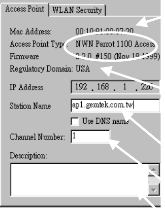
Read-only features shown include hardware address, brand and version, and the regulatory domain.
Hardware address (MAC address)
Brand, type, and version
information.
The regulatory domain for which
the Access Point has been
configured (factory setting). Note
that it is illegal to use the Access
Point outside the designated
domain. See Regulatory Domains
for details.
The IP address and the hostname
of the Access Point.
The radio channel number. The
permissible channels depend on
the Regulatory Domain.
An optional description field for
easy reference.
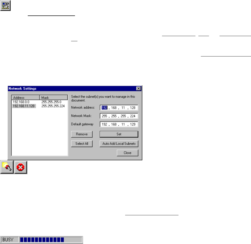
4.4.1 Network Settings Dialog
Selecting the Edit/Network Settings… menu item (or clicking the corresponding toolbar button) pops up the Network Settings
dialog. Use this dialog to inform APManager™ about your network configuration. APManager™ needs this information to be
able to scan for Access Points.
Add your network addresses (subnets) by entering the correct information in the Network address, mask and default gateway
fields in the dialog, and clicking the Set button for each network/subnet. To view the details of a particular network, click on the
Address field in the list. Click the Remove button to delete a network from the list.
If the computer on which APManager is running is connected to all your networks directly, you can try Auto Add Local Networks
to insert them in the list. Note: if subnetting is used, the network addresses and masks generated by this function may not be
correct and should be adjusted manually.
4.4.2 Searching for Access Points
APManager™ has an easy-to-use Access Point discovery function that simplifies the administration of the Access Points in your
network. You normally apply the Search function in one of the following situations:
New Access Points have been added to the network
The IP address of one or more Access Points is no longer valid or known, possibly because the DHCP or BOOTP server
has assigned it a different IP address. You may be informed of this fact because the Access Points will be reported off-line
by APManager™.
Invoke the Search function by selecting the menu command Edit/Search Access Points, or pressing the associated toolbar
button. While APManager™ is scanning the network, you may continue work on the document. If necessary you can abort a
scan by clicking on the Abort Search button.
A progress indicator will be shown in the status bar.

4.4.3 Manually programming IP addresses
The preferred method of providing IP addresses for your Access Points is applying a DHCP or BOOTP server in your network. If
you do, the Access Points will acquire an IP address automatically from this server.
If you do not have a DHCP server it is possible to set the IP address of your Access Points from APManager™.
1. Physically connect the Access Points and the computer on which you run APManager™ to the same Ethernet segment.
2. Make sure there is no DHCP or BOOTP server running.
3. Switch the Access Points on. The network LED should light up in red.
4. Configure the network you want your Access Points to be part of. See Network Settings Dialog for details.
5. Enter the hardware addresses of the Access Points by hand using the Edit/Insert Access Point menu command or clicking
the appropriate toolbar button.
6. For each Access Point select Edit/Set IP Address menu command and enter the required IP address manually. As soon as
you press apply, the Access Point should acquire the designated IP address. Within a few seconds the network LED on the
Access Point should light up green.
Note that you may or may not be able to communicate with the Access Point, depending on the validity of the IP address in
the current Ethernet segment.
4.5 Managing Security
Maintaining security in a wireless LAN environment is somewhat different from a wired network, because the radio waves do not
stop at your office walls. Eavesdropping or unauthorised access from outside your building can be a serious threat.
There are three types of actions involved:
Protecting your data while it is transferred from one station to another. Encryption techniques will be necessary in most
environments (Data Privacy).
Control who can make use of the wireless network (Access Control).
Protecting your network configuration against tampering from both inside and outside your organisation (Secure
Management).
Data Privacy An WX-1500SB Access Point supports three different
data privacy algorithms: unencrypted data;
standardised IEEE 802.11 WEP (based on a 40 bit
shared key), and No Wires Needed AirLock™ (based
on automatically generated 128 bit session keys).
Access Control The IEEE 802.11 standard allows for Access Control
rules based on the client station’s hardware address,
and is fully implemented by the WX-1500SB. If
AirLock™ is enabled, the hardware address is also
verified using cryptographic techniques. See the section
on AirLock™ Security Architecture.
Secure
Management
The primary protection against tampering for any SNMP
agent is the Write Community String (WCS), which
functions as a password for network management
commands. The WCS is sent over your network in plain
text, making it vulnerable to eavesdropping from within
your organisation. The WCS is never sent over the
radio, however.
If you want you can lock your Access Points. After
being locked they can no longer be managed via
SNMP. Press the pinhole Reset switch on the back-
panel of the Access Point to unlock the Access Point.
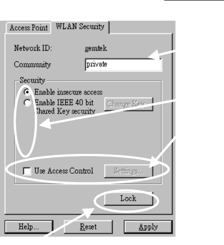
Select the required security options in the WLAN Security property sheet.
Use this button to lock the settings of the
Access Points (almost) permanently
Edit the Community String
field to modify the SNMP
Write Community String for
all Access Points in the
selected WLAN.
Select the data privacy
algorithm(s) you want to
support in the Access Points.
See the section Access
Control for details.
.
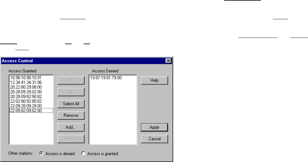
4.5.1 Access Control
Within the IEEE 802.11 framework, Access Control is based on the hardware address of the client stations. Per client you can
select whether or not it will be allowed access to your wireless network infrastructure. On the WLAN Security tab, check the Use
Access Control box to enable Access Control. If this box is not checked, any client station can associate with your network.
Click the Access Control Settings… button on the WLAN Security tab to pop up the Access Control Dialog. Press Add… to enter
the client stations you want to grant access.
A default rule determines whether unregistered stations can join. You can move clients between Access Granted and Access
Denied lists by clicking the >> and << buttons or pressing the left and right arrow keys.
Press Apply to confirm your changes and close the dialog.
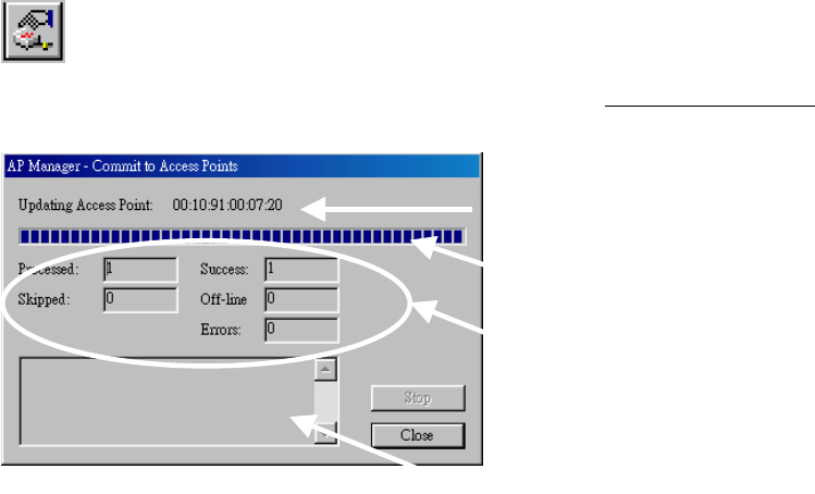
4.6 Updating Access Point Settings
After modifying the open APManager™ document you should update the Access Points in your network with the new settings.
This is done for all Access Points simultaneously by selecting the File/Commit to Network menu command. Or clicking the
associated toolbar button. During the update the following Dialog is displayed:
Access Point that
is currently being
processed.
Progress indicator
Update result
counters. The
‘Skipped’ count
refers to Access
Points in the
‘Unused’ special
WLAN.
Specific error
messages.
Within 10 seconds after the Access Point has been successfully updated it will disconnect all client stations that are joined with
it, and restart with the new settings. While restarting it will show red LEDs for a short period of time.
4.7 IEEE 802.11 WEP Security
The IEEE 802.11 standard includes a Shared Key data privacy mechanism, called ‘Wired Equivalent Privacy’.
Features of WEP are:
Data encryption using a 40 bit shared key
No key distribution mechanism. The shared key (password) must be distributed manually to all personnel and either be
remembered or stored somewhere on the hard disk.
Simple authentication of clients based on hardware address.
4.8 More about Cells
Each Access Point in the network forms the centre of a cell, or BSS. The Cells should overlap slightly to guarantee seamless
wireless connectivity everywhere. Nearby Access Points should preferably send and receive on different channels for maximum
throughput.
Creating a cell plan for your site can be complicated, and is usually done by experts employing special measuring equipment.
Furthermore, the radio channels you may use depend on both the capabilities of the PC-Cards you are deploying, as well as the
regulations in your area.

The following table may be of help:
Regulatory
Domain
Area Permissible
Channels
FCC United States 1 – 11
DOC Canada 1 – 11
ETSI Europe except
Spain and France
1 – 13
MKK Japan 1-14
4.9 Compatibility
The APManager utility version 1.1.0 is compatible with the GemTek WX-1500SB Access Points only.
5 Glossary
BSS “Basic Service Set”. De facto an alias for Access
Point.
Cell Area in which the radio signal of an Access Point
is sufficiently good to join with it.
ESS “Extended Service Set”. A group of Access
Points with identical settings among which a
client system can roam. An ESS forms the heart
of a WLAN.
Shared Key Algorithm Encryption scheme for which both sender and
receiver need to know the (same) encryption
key.
SNMP “Simple Network Management Protocol”
WLAN “Wireless LAN” The set of Access Points and
Wireless Clients that form a local area network.
Write Community String SNMP password
WEP “Wired Equivalent Protection”
Data privacy mechanism based on a 40 bit
shared key algorithm, as described in the IEEE
802.11 standard
6 Technical specifications of WX-1500 / 1520
6.1 Standards supported
ϑ IEEE 802.11 standard for Wireless LAN
ϑ All major networking standards (including IP, IPX)
6.2 Environmental
Operating temperature (ambient):
ϑ -10 ~ 50°C
Humidity:
ϑ Max. 95% Non-condensing
6.3 Power specifications
DC power supply
ϑ Input : DC 100-240 50-60 Hz 1A
ϑ Output: 5V DC 1A converter incl.
6.4 Radio specifications
Range:
ϑ per cell indoors approx. 35-100 meters
ϑ per cell outdoors up to 100-300 meters
Transmit power:
ϑ Nominal Temp Range: 14 dBm, 12min.
ϑ Extend Temp Range: 14 dBm, 11 dBm min.
ϑ Transmit Power, 2.7 v to 3v: 14 dBm max,11 dBm min.
Frequency range:
ϑ 2.4-2.4835 GHz, direct sequence spread spectrum
Number of Channels:
ϑ Most European countries: 13
ϑ US and Canada: 11 (3 non-overlapping)
ϑ France: 4 (1 non-overlapping)
ϑ Japan : 14
Antenna system:
ϑ Dual antenna diversity system; 2dB gain with swivel neck
6.5 Specific features
Supported bit rates:
ϑ 11 Mbps : CCK
ϑ 5.5 Mbps : CCK
ϑ 1 Mbps : DBSK
ϑ 2 Mbps : DQPSK
Data encryption:
ϑ 40-bit WEP Encryption
Utility Software:
ϑ AP Manager to manage wireless LAN, network connection and client access control
6.6 Physical Dimensions
136 x 126 x 40 mm, 227 x 126 x 40 mm with antennas extended