Gempack TC7370 WBT with 15-inch LCD Monitor User Manual manual
Gempack Co., Ltd. WBT with 15-inch LCD Monitor manual
UserManual.wiki
>
Gempack
>
TC7370 User Manual
Users Manual
Navigation menu
Upload a User Manual
Namespaces
Wiki Guide
HTML
PDF
Info
Views
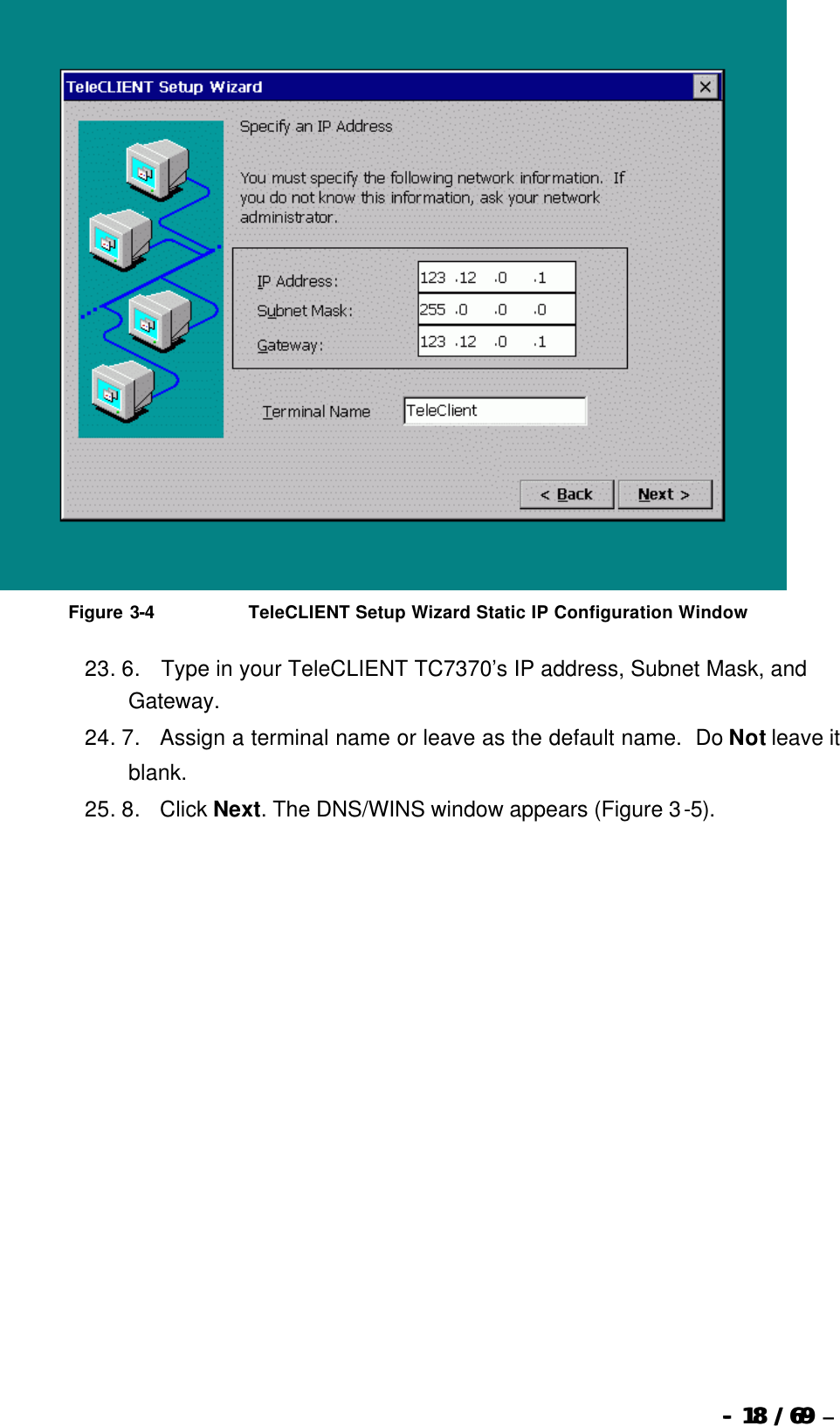
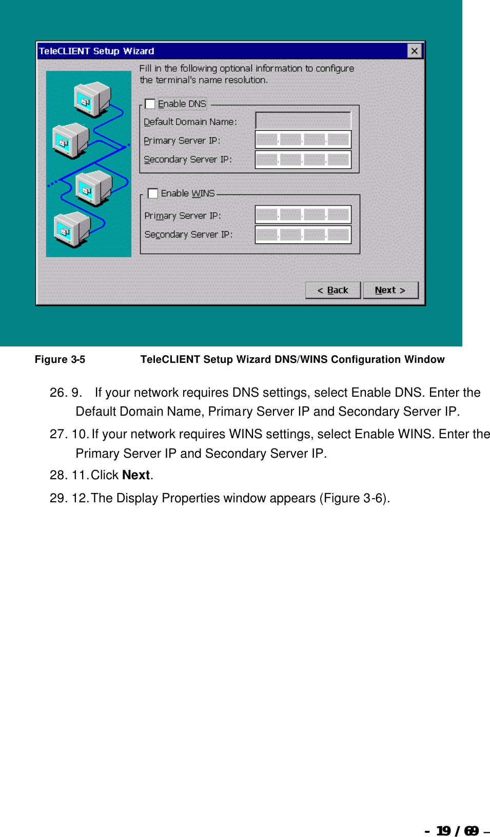
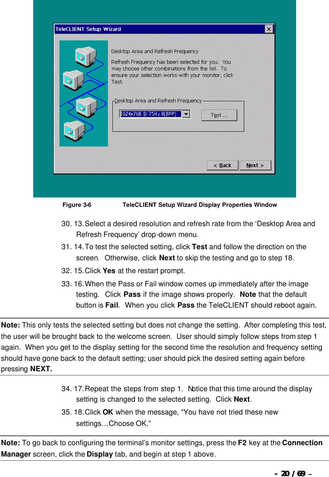
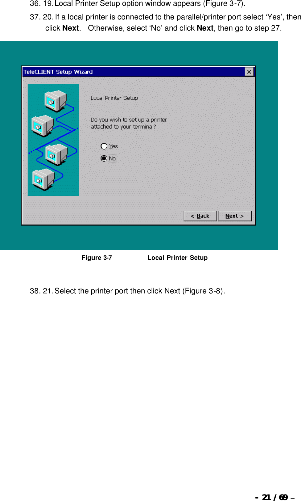
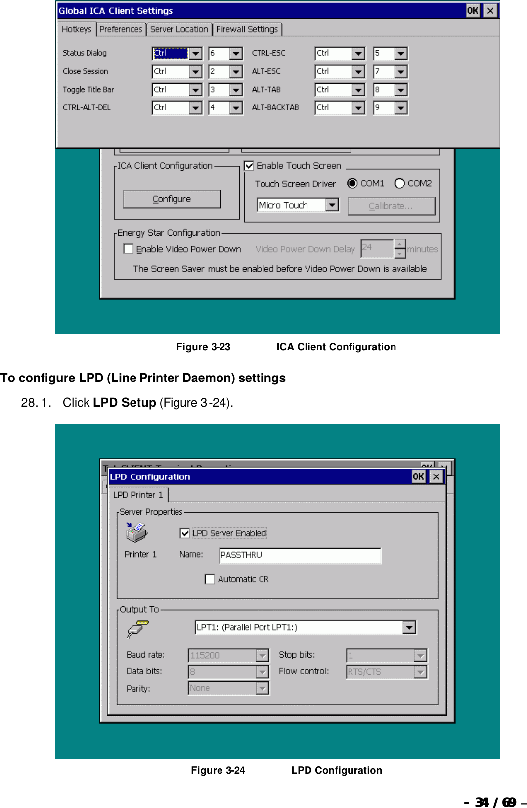
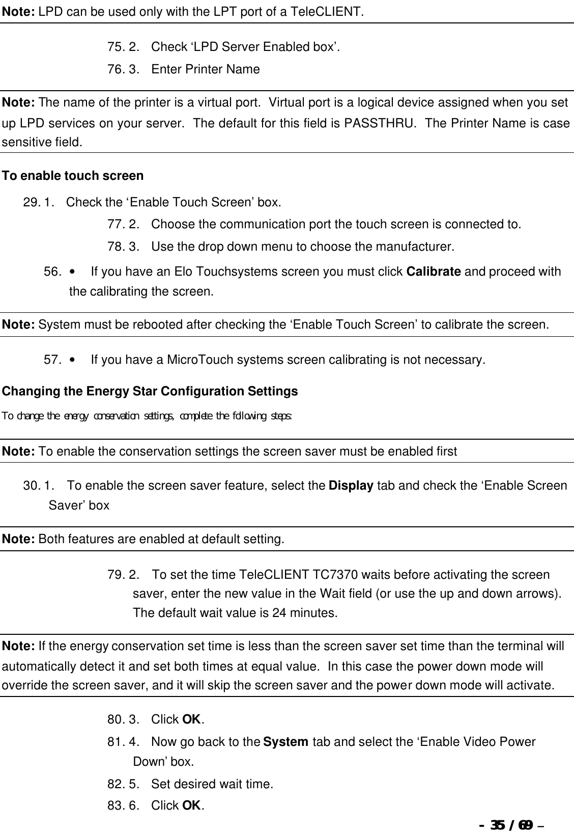
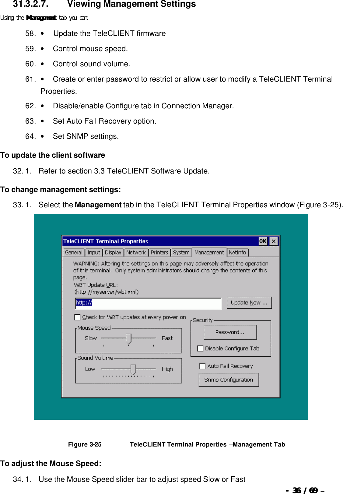
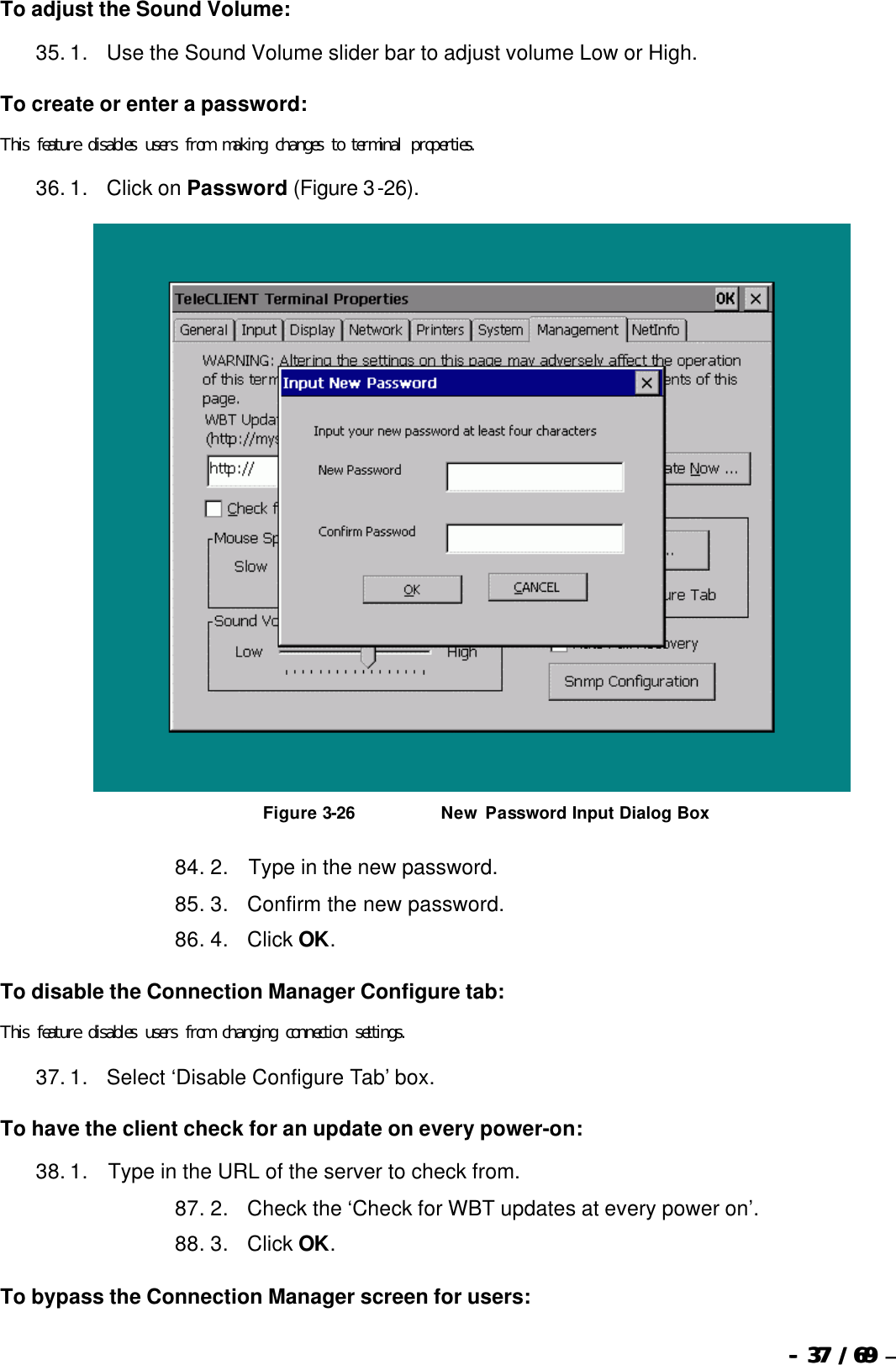
User Manual
Discussion / Help
Navigation