Gemstar Communications GSPS-ACT-02 User Manual TDMA principles of operation mod
Gemstar Communications Inc TDMA principles of operation mod
Contents
- 1. Technical Manual
- 2. TDMA Activator Principle of Operation Supplementary Manual
TDMA Activator Principle of Operation Supplementary Manual

TDMA Activator Principle of Operation
TDMA Activator
Principle of Operation
Supplementary Manual
May 4, 2000

TDMA Activator Principle of Operation
TABLE OF CONTENTS
INTRODUCTION ...................................................................................................................................................... 3
1-TYPE OF UNITS..................................................................................................................................................... 3
1.1-AUTONOMOUS................................................................................................................................................ 3
1.2-MASTER............................................................................................................................................................ 3
1.3-SLAVE ............................................................................................................................................................... 3
2-TIME SLOTS .......................................................................................................................................................... 3
3-SYNCHRONIZATION........................................................................................................................................... 4
4-RE-SYNC and LOSS OF SIGNAL........................................................................................................................ 4
5-USE OF TIME BLOCKS ....................................................................................................................................... 4
6-HARDWARE........................................................................................................................................................... 6
7-RF DATA FORMAT............................................................................................................................................... 7
7.1-ENCODING...................................................................................................................................................... 7
7.2-SLAVE AND AUTONOMOUS ACTIVATOR DATA SEQUENCE........................................................... 7
7.3-MASTER ACTIVATOR DATA SEQUENCE............................................................................................... 8
8-KNOWN LIMITATION......................................................................................................................................... 8
9-INSTALLATION..................................................................................................................................................... 9
9.1-ANTENNA TYPES........................................................................................................................................... 9
9.2-POWER SETTING AND ANTENNA GAINS............................................................................................... 9
9.2.1-MAX POWER FOR MONO-POLE........................................................................................................ 9
9.2.2-MAX POWER FOR PATCH................................................................................................................... 9
9.3-POWER SETTING AND ADJUSTING......................................................................................................... 9
TDMA Activator Principle of Operation
INTRODUCTION
The TDMA (Time Domain Multiple Access) mode activator system uses a synchronised time
keeping system to permit various activators to transmit their signals without causing interference
to other activator. This is done by defining time slots and permitting any given activator to
transmit only within selected time slots. By insuring no two overlapping activator fields have the
same time slot, interference should not be an issue.
1-TYPE OF UNITS
There are 3 basic modes the activators can operate in:
• 1.1-AUTONOMOUS Operates without regards to time slots. This was the original mode
of operation. It has uses where no time base signal can be presented and transmits at all
times
• 1.2-MASTER There is usually only one master unit in a system. It sends the time
base count based on it own internal clock, starting at 1 when reset. The Master only
transmits during its selected time blocks.
• 1.3-SLAVE This is the most used mode. When the unit operates as a slave it
first must receive a valid time base signal from the Master unit to synchronize its internal
counter to match the master unit. Once that has happened, it then transmits during its
selected time blocks and received time base sync. signals when not in transmit mode.
2-TIME SLOTS
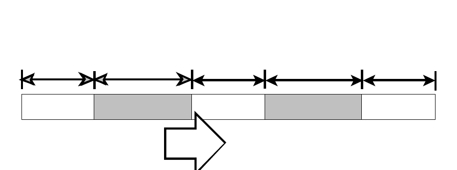
Time is split into 6 units, each unit being 40 seconds long. The system repeats the time
loop cycle every 240 seconds (4 minutes) That is, the system starts in time block (slot) 1 doing
what is programmed for this time block, then moves to time block 2 and so on. At the end of
block 6, the system resets back to beginning of block 1.
Block 1 Block 2
Block 1 Block 2 Block 3 Block 4 Block 5 Block 6
Repeat loop
The Duration of each block was selected based on the fact that the current postal tag
wakes up every 32 seconds. By using a time block of 40 seconds, we insure that the
postal tag will have two reading every time slot.
The control and determination of time blocks or slots is determined by internal time
keeping clocks that count from 1 to 240 seconds. Where block 1 is 1 to 40 seconds,
block 2 is 41 to 80 seconds and so on.
The selection of time block for transmit for each activator is done by a 6 position dip
switch. Each pole of the switch represents a single time block. The activator’s processor
reads the switch every few seconds and depending if the switch is open or closed for a
given time block, the software will either activate the transmitter or receive modes.
3-SYNCHRONIZATION
For the system to work, all slaves must have same time count as the master unit. The
slave units must not transmit until they have synchronized their internal time count to the
master unit, and the correct time block is active.
The slave units turn on their receiver at reset time and clear their valid time flag. They
then receive signals until a valid time base signal is found. Once that occurs, the software
sets the valid time flag and the units begins to compare the current time block numbers
(time base count divided by 40) to the setting on the time block selection dip switch.
4-RE-SYNC and LOSS OF SIGNAL
Once the activator is synchronized, it constantly adjusts it internal count to match the
master time base signal during times it is not in transmit mode and the master time base is
present. A time stamp is made of each re-sync point. If the unit fails to re-sync for a
period of 1 hour, the unit shall return to the reset state and halt any further transmission
until it can find the time base again. This is done to prevent the unit from getting too far
off target time, as its internal clock is subject to about 1 min per day max error.
5-USE OF TIME BLOCKS
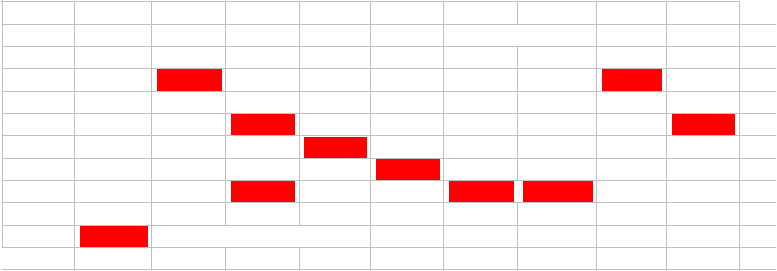
The following chart shows 1 master and 4 slave units each set to various time block
setting.
block 2block 1block 6block 5block 4block 3block 2block 1settingunit
100000Master
010000Slave 1 001000Slave 2 000100Slave 3 010011Slave 4
=TRANSMITTING
Master unit It is set to send in block(slot) 1. There is no specific requirement to have the
master operate in this slot, but for this chart is set here. Thus during time block 1's, the
master activator sends its signal. During the other 5 blocks of time it sits idle.
Slave 1This unit is set to operate in block 2. Thus it transmits during block 2 and receives during
the other 5 time blocks
Slave 2This unit is set to operate in block 3. It would most likely be a neighbour of Slave 1
Slave 3This unit is set to operate in block 4. It could neighbour on slave 1 and 2 without
interference.
Slave 4This unit is set to transmit in blocks 2, 5 and 6. It would not be a neighbour of slave 1
due to the block 2 transmit time, but could neighbour on the other two slave units. It
sends signal ½ the time and therefore would be used in areas where a higher chance of
being received by a postal tag is required such as a receiving area etc.
6-HARDWARE
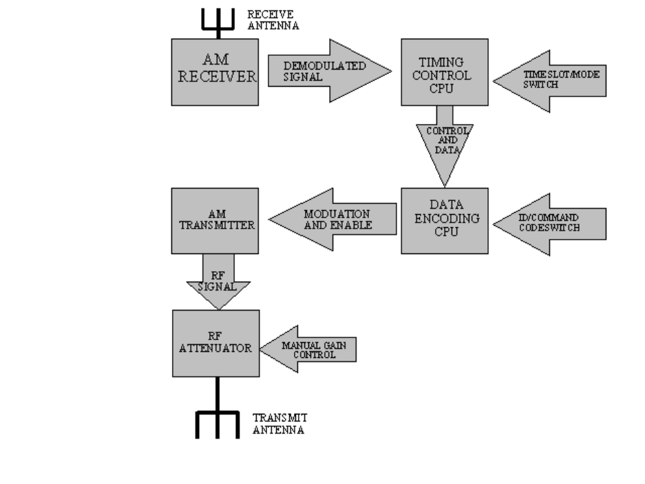
The above diagram relates the core components of the activator unit.
• The AM receiver and its external antenna pick up the signal from a Master
Activator (916 MHz) which is an Amplitude Modulated signal. The Receiver
demodulates this and present it to the timing control cpu
• The TIMING CONTROL CPU performs a number of tasks
• Decode the data from the receiver and look for time base signal
• maintain time count using a crystal control timing reference
• load and compare time/slot switch data and determine when to transmit
• provides control commands to the data encoding CPU
• The DATA ENCODING CPU under the control of the timing control cpu reads
the contents of the external ID/command switch and combines this with data from
the control cpu. When so directed, it turns on the AM transmitter and formates
the data as required for reception by the postal tags
• The AM transmitter is a hybrid unit operating at 916.5 MHz. This unit generates
a low power RF signal (0 dBm or less). Operation is On-Off-Keying (OOK) mode
where the digital signal either turns carrier full on (logical 1) or fully off (logical
0)
• The RF ATTENUATOR allows the installer to reduce the output RF signal level
to a much lower level to reduce the coverage area of the unit
7-RF DATA FORMAT
The activator system transmits data using a low power OOK (on-off-keying) Amplitude
Modulation system. The format of the data and data rate were determined by the
characteristics and limitations of the RF transmitter/receiver components.
7.1-ENCODING
The data is encoded in such a manner that the overall signal has a 50% duty cycle
(within a few percent) regardless of data content. This is required to maintain DC
balance of the signal as presented to the data slicer internal to the receiver module.
To provide the objective of DC balance, the data format includes both true and
complement forms of the original data, plus additional padding bits. The
complement data is redundant and thus provides a means of simple error checking
based on comparing the true and complemented data received.
7.2-SLAVE AND AUTONOMOUS ACTIVATOR DATA SEQUENCE
Dotting Dotting DottingID dataID data
6 mS 6 mS 6 mS10 mS 10 mS
The slave and autonomous activators use the simplest format of data transmission.
The sequence starts with 6 mSec of dotting. This is a simple 5 KHz on/off
sequence which allows the receiver to sync up to the incoming data stream. The
normal data stream will never contain this long of sequence of on/off cycle in a
row. The dotting is followed by 10 mSec of data, again at the same bit rate, and
includes 48 bit elements for the 8 bit transmission (true and complement data plus
padding). The cycle continuously repeats the cycle about 60 times per second
when the activator is in active transmit mode.
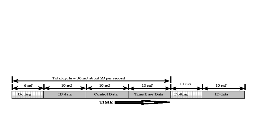
7.3-MASTER ACTIVATOR DATA SEQUENCE
The master uses the same encoding method as used for the slave activator system. The
same dotting and ID data fields are sent. However a second data field is attached to the
end of the ID data field. This field contains the 8 bit time base count value and is
encoded in the same manner as the ID field with 48 bits used. This extends the length of
the data sequence to 26 mSec
8-KNOWN LIMITATION
• The system is limited to how far the low power master activator can send its
signal to the slave activators. This is typically about 100M max. in open space.
The real range is reduced by obstruction in the path such as low ceiling, metal
machines and overhead assemblies etc.
• The slave units will operate for 1 hour without the master signal. It is possible
that when there is a power failure at the master only, it may start its time base
count at a point where it transmits when one or more slave are also transmitting
due to new vs. old time base count values. During such an event, it may take
some amount of time (up to the hour in worst case) before the slave units are in a
receive mode at the same time as the master is sending data, and not being
blocked by some other slave activator.
9-INSTALLATION
9.1-ANTENNA TYPES
The system uses two primary types of antennas.
• The non-directional mono-pole unit with ground plane. This is a low gain
non-directional unit for coverage over a large circular area.
• The directional patch antenna. This is a high gain antenna that projects the
signal over a narrow coverage of about 90 degrees (45 degrees either side
of the line formed at right angles to the front surface of the antenna)
9.2-POWER SETTING AND ANTENNA GAINS
To comply with radio regulations the power level must be kept below 50,000
uV/M (+94 dBuV/M) measured 3 M. from the antenna, at the point of strongest
signal. For an isotropic antenna (gain=1), this happens at a power input level of
-1.2 dBm for steady carrier. As we transmit only 50% of the time, we have a 3 dB
margin and can have a peak input power level of +1.8 dBm to the same type of
antenna. The isotropic antenna is not practical to construct, however it forms the
basis for comparing input power to the resultant field strength. An antenna with a
gain of 5 dBi produces a field strength 5 dB stronger than an isotropic antenna for
the same input power. Thus if we can have an input power of +1.8 dB for an
isotropic, for the +5 dB gain antenna, we must reduce our power to 1.8-5 dBm or -
3.2 dBm.
9.2.1-MAX POWER FOR MONO-POLE
In the case of our two antennas, the mono-pole has a measured gain of 1.3 dBi
when attached to the normal feed port of the activator using RG-59 cable and the
cable, with a F connector on one end and TNC connector on the other, where this
cable is 4 inches (10 cM) in length. This imply the maximum non-modulated
peak carrier level can be as high as (1.8-1.2) +0.6 dBm. For the patch antenna. If
longer cables are used, the power may be increased according.
9.2.2-MAX POWER FOR PATCH
The gain is measured the patch antenna is +8.7 dBi. Thus the nominal maximum
peak carrier input should be no more than -6.9 dBm. Compensation for longer
cables can be made (consult details of cable for loss per meter)
9.3-POWER SETTING AND ADJUSTING
The power of the unit is adjusted by the rotary control pot. near the output port.
An internal pot. sets the maximum limit value for the external pot. The normal
setting of the units are to limit the output port power to -3 dBm. The external
control provides 25 to 30 dB adjustment range of further attenuation. (range
determined by setting on internal pot.)
The power level can be measured by connecting the output port with a cable of
known loss to the input of the power meter or spectrum analyser, and if the case is
open, connect the modulator transistor’s base pin to ground to force carrier on.
The level read is the true peak power.
If the signal is being measured with externally only, and a modulated signal is
presented, the determination of correct setting depends on the type of meter or
detector present. An averaging detector or meter (averages volts), results in a
reading with is ½ the voltage (average voltage, not average power). This is -6dB
down from the peak, or -3 dB below the true average power level. An RMS
responding meter would report the correct average power. If a peak reading
detector or meter (or Q-Peak) the results should be very close the same reading
that would be taken if the carrier was locked on and therefore directly read.