GemTek Technology A901023 Wireless LAN Access Point User Manual WX 1590 manual
Gemtek Technology Co., Ltd. Wireless LAN Access Point WX 1590 manual
UserManual.wiki
>
GemTek Technology
>
A901023 User Manual
Manual
Navigation menu
Upload a User Manual
Namespaces
Wiki Guide
HTML
PDF
Info
Views
User Manual
Discussion / Help
Navigation


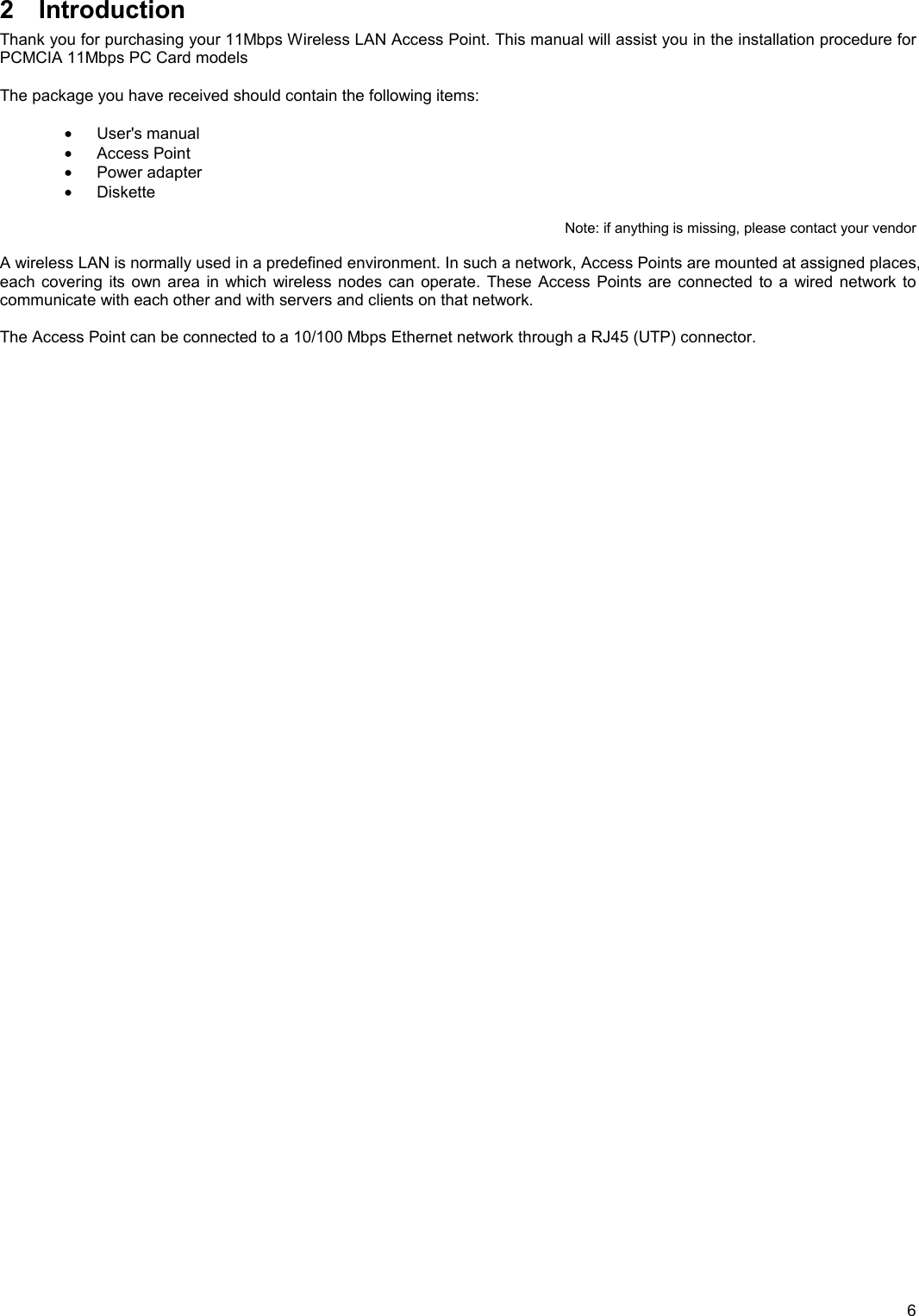
![8Step 3. Modify IP address to same subnet Under DOS prompt and type c:\>arp -s [IP address] [MAC address] Note: Arp: address resolution protocol -s: change IP address [IP address]: target IP address [MAC address]: MAC address of Access Point](https://usermanual.wiki/GemTek-Technology/A901023/User-Guide-217791-Page-8.png)

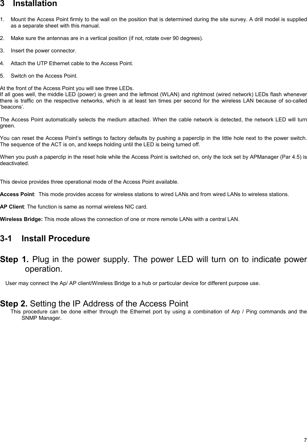
![10Step 5. Trace IP address by using “Ping” Under DOS prompt and type c:\>ping [IP address] Step 6. Launch “AP SNMP” program “Start” “Programs” “SNMP” “SNMP manager.](https://usermanual.wiki/GemTek-Technology/A901023/User-Guide-217791-Page-10.png)