GemTek Technology A950806AG Dual Radio 2.4GHz/5GHz Access Point User Manual BW1250 UG EN Revised
Gemtek Technology Co., Ltd. Dual Radio 2.4GHz/5GHz Access Point BW1250 UG EN Revised
UserManual.wiki
>
GemTek Technology
>
A950806AG User Manual
Manual
Navigation menu
Upload a User Manual
Namespaces
Wiki Guide
HTML
PDF
Info
Views
User Manual
Discussion / Help
Navigation
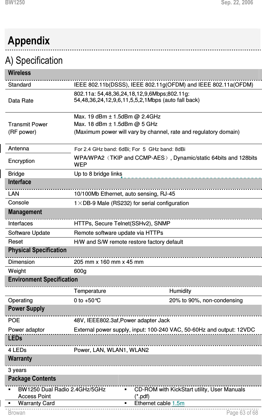
![BW1250 Sep. 22, 2006 Browan Page 5 of 68 Purpose This document provides information and procedures on hardware installation, setup, configuration, and management of the BROWAN high performance Dual Radio 2.4GHz/5GHz AP BW1250. Prerequisite Skills and Knowledge To use this document effectively, you should have a working knowledge of Local Area Networking (LAN) concepts and wireless Internet access infrastructures. In addition, you should be familiar with the following: Hardware installers should have a working knowledge of basic electronics and mechanical assembly, and should understand related local building codes. Network administrators should have a solid understanding of software installation procedures for network operating systems under Microsoft Windows 95, 98, Millennium, 2000, NT, and Windows XP and general networking operations and troubleshooting knowledge. Conventions Used in this Document The following typographic conventions and symbols are used throughout this document: Very important information. Failure to observe this may result in damage. Important information that should be observed. Additional information that may be helpful but which is not required. bold Menu commands, buttons and input fields are displayed in bold code File names, directory names, form names, and system-generated output such as error messages are displayed in constant-width type <value> Placeholder for certain values, e.g. user inputs [value] Input field format, limitations, and/or restrictions. Help Us to Improve this Document! If you should encounter mistakes in this document or want to provide comments to improve the manual please send e-mail directly to: manuals@browan.com BROWAN Technical Support If you encounter problems when installing or using this product, please consult the BROWAN website at www.browan.com for: Direct contact to the BROWAN support centers. Frequently Asked Questions (FAQ). Download area for the latest software, user documentation and product updates. About this Guide](https://usermanual.wiki/GemTek-Technology/A950806AG/User-Guide-720874-Page-6.png)

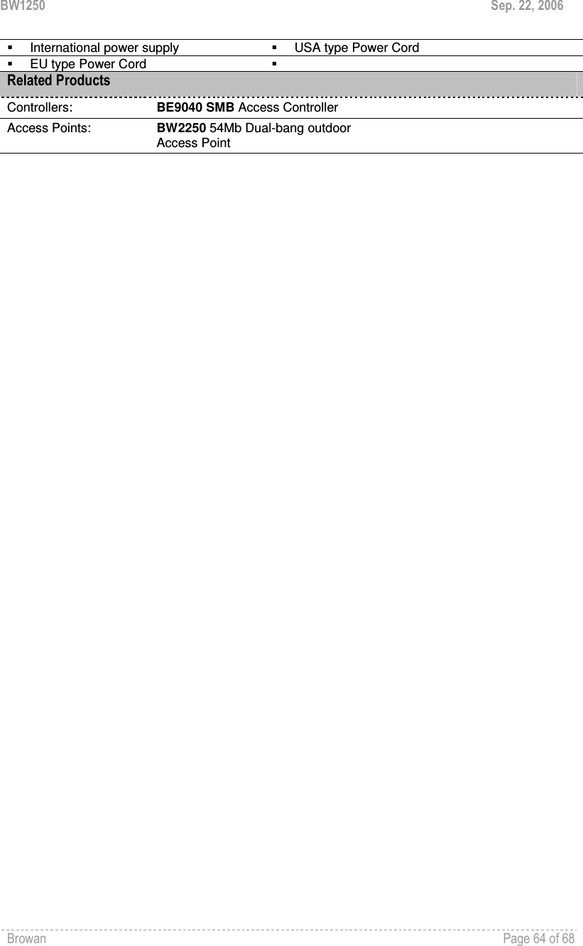
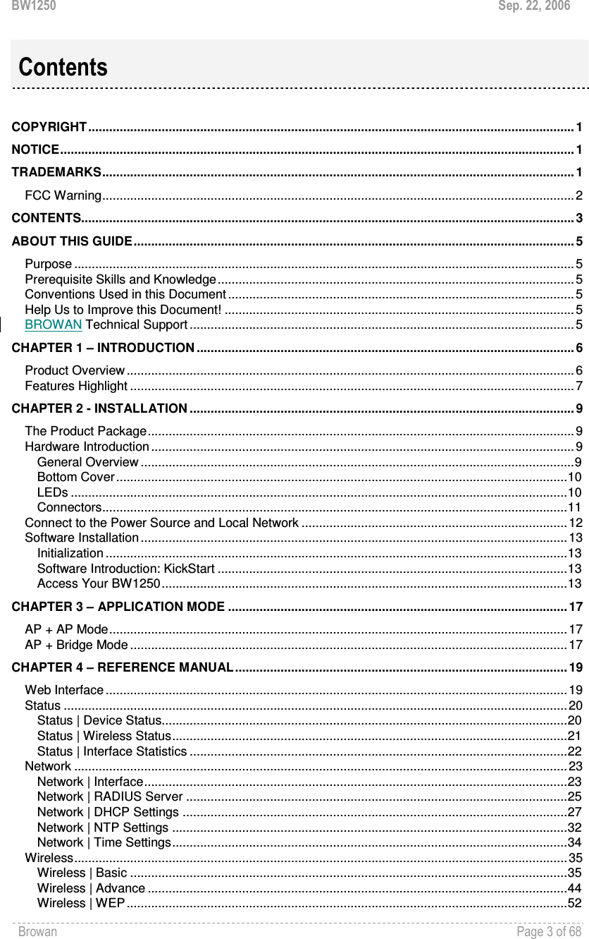
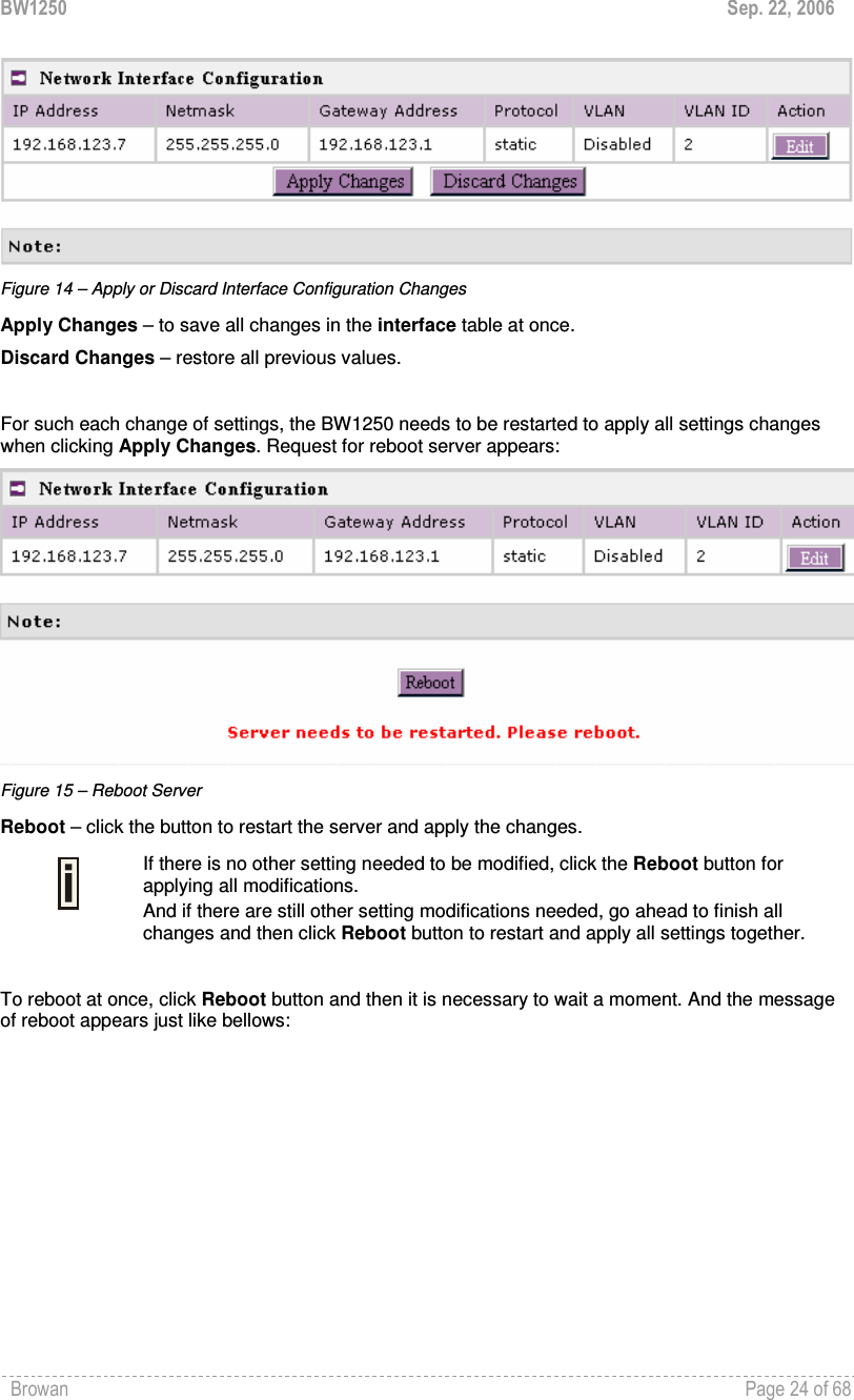
![BW1250 Sep. 22, 2006 Browan Page 23 of 68 Network Network | Interface The interface configured is bridge device therefore only one interface is displayed here for configuration. Bridge interface and its settings are listed in the Interface page. Figure 12 – Interface Configuration Table To change network interface (bridge) configuration properties click the Edit button in the Action column. The status can be changed now: Figure 13 – Edit Interface Configuration Settings IP Address – specify new interface IP address [in digits and dots notation, e.g. 192.168.123.70]. Netmask – specify the subnet mask [[0-255].[0-255].[0-255].[0-255]].These numbers are a binary mask of the IP address, which defines IP address order and the number of IP addresses in the subnet. Gateway Address – interface gateway. For Bridge type interfaces, the gateway is always the gateway router. Protocol – specify static for setting IP address manually and dhcp for getting IP address dynamically acting as DHCP client. When dhcp is used for getting IP address, Kickstart is strongly recommended to find your device. VLAN - specify whether to manage this device via VLAN. VLAN ID _ specify VLAN ID when managing this device via VLAN. Save – save the entered values. Cancel – restore all previous values. Change status or leave in the default state if no editing is necessary and click the Save button.](https://usermanual.wiki/GemTek-Technology/A950806AG/User-Guide-720874-Page-24.png)
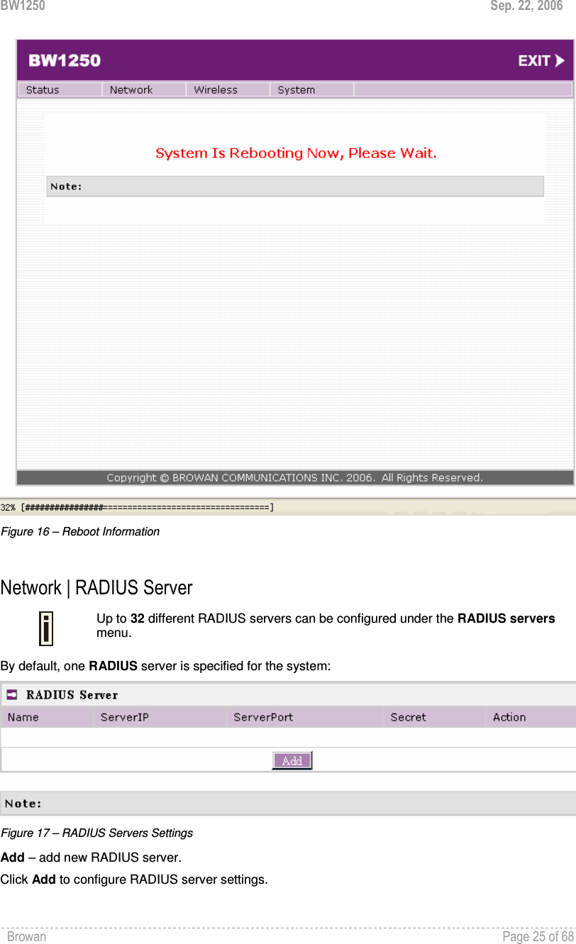
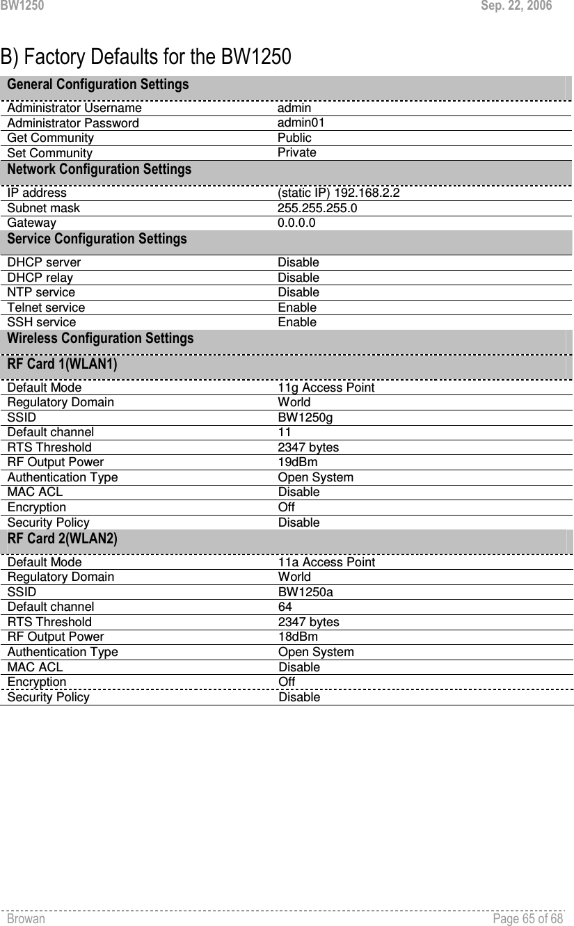
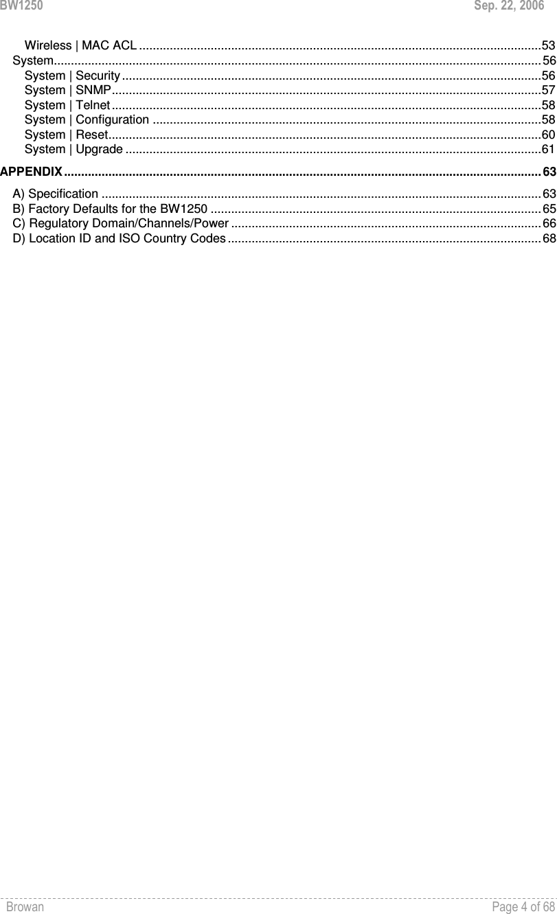
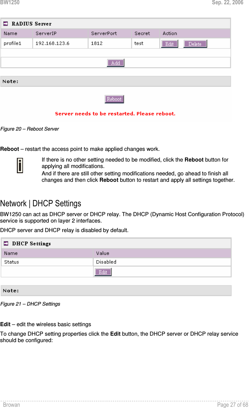
![BW1250 Sep. 22, 2006 Browan Page 26 of 68 Figure 18 – RADIUS Server's Details Name – specify the new RADIUS server name which is used for selecting RADIUS server. Server IP – authentication RADIUS server IP address [dots and digits]. Server Port – specify the network port used to communicate with RADIUS [1-65535]. The default port value for authentication is 1812. The default port value for accounting is 1813. The port specified here must be the same with the one on the RADIUS server. Secret – shared secret string that is used to make sure the integrity of data frames used for authentication server. Save – add new specified RADIUS server. Cancel – restore all previous values. After adding a new RADIUS server or editing an existing one, the following control appears: Figure 19 – Apply or Discard RADIUS Server Changes Edit – edit an existing RADIUS server settings Delete – delete an existing RADIUS server settings Click Apply Change to apply all the changes. Then the follow similar page will appear:](https://usermanual.wiki/GemTek-Technology/A950806AG/User-Guide-720874-Page-27.png)
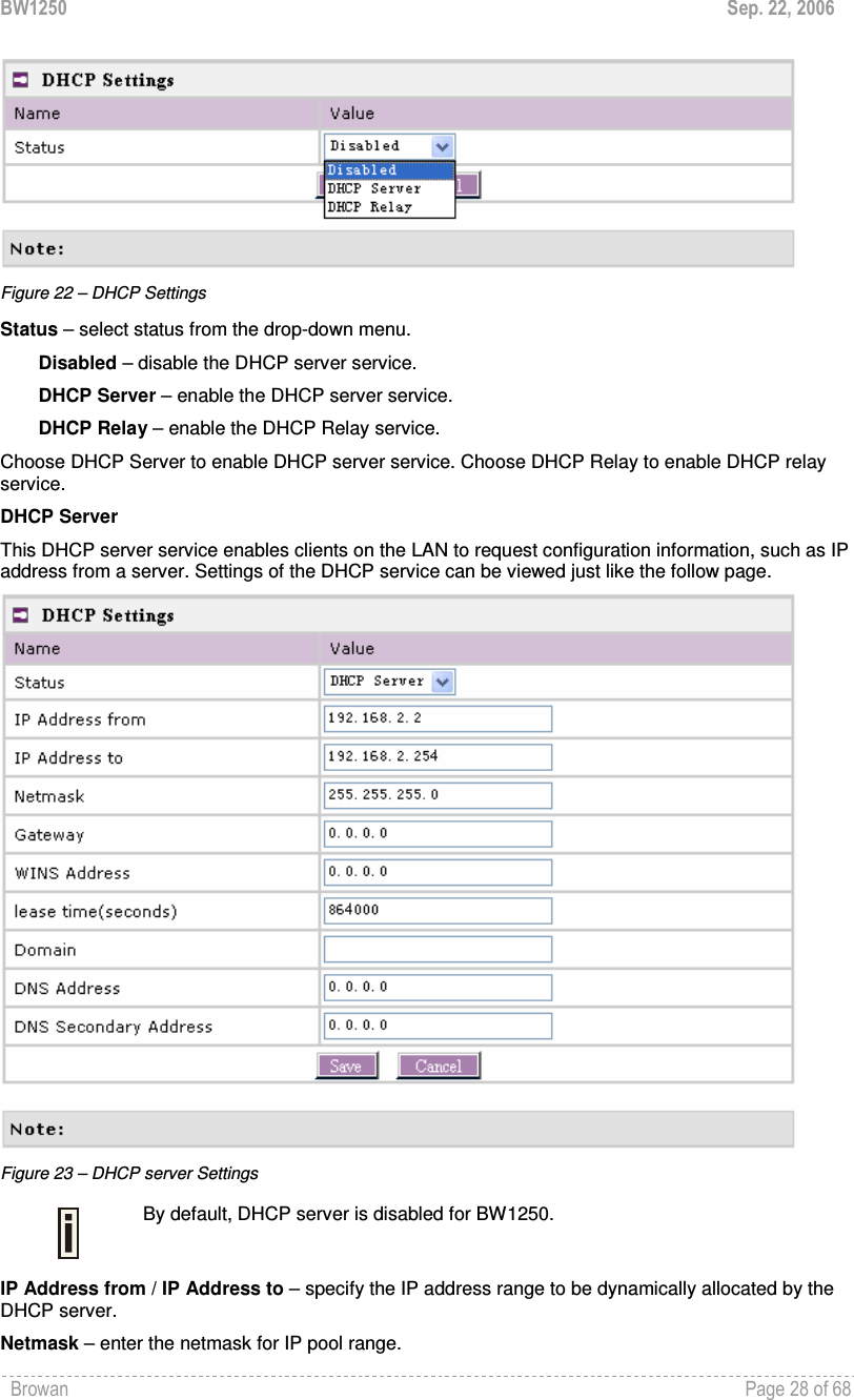
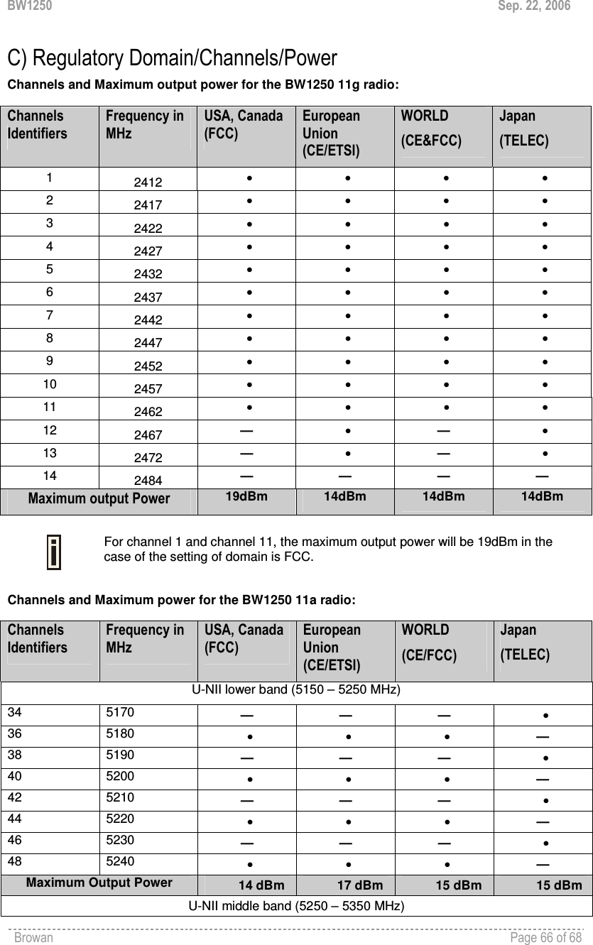
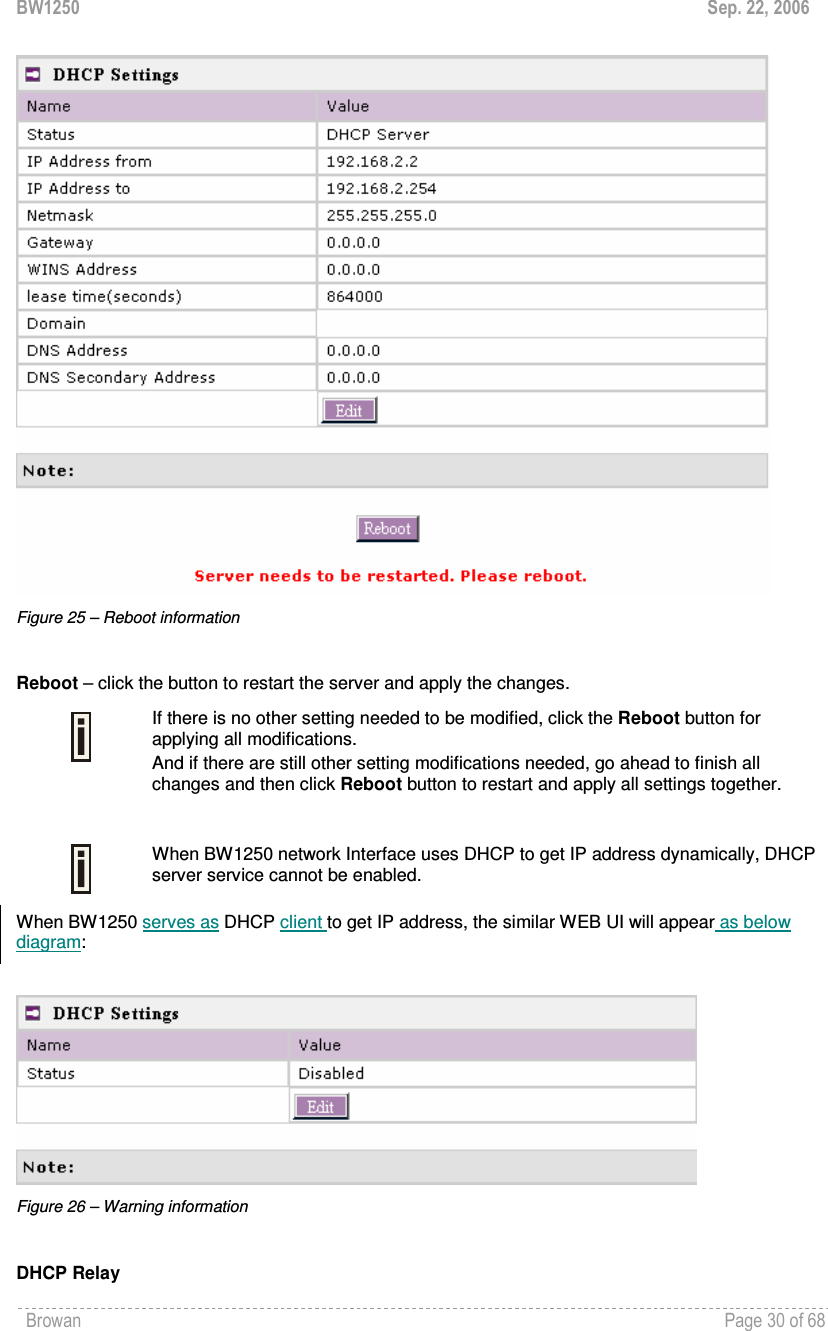
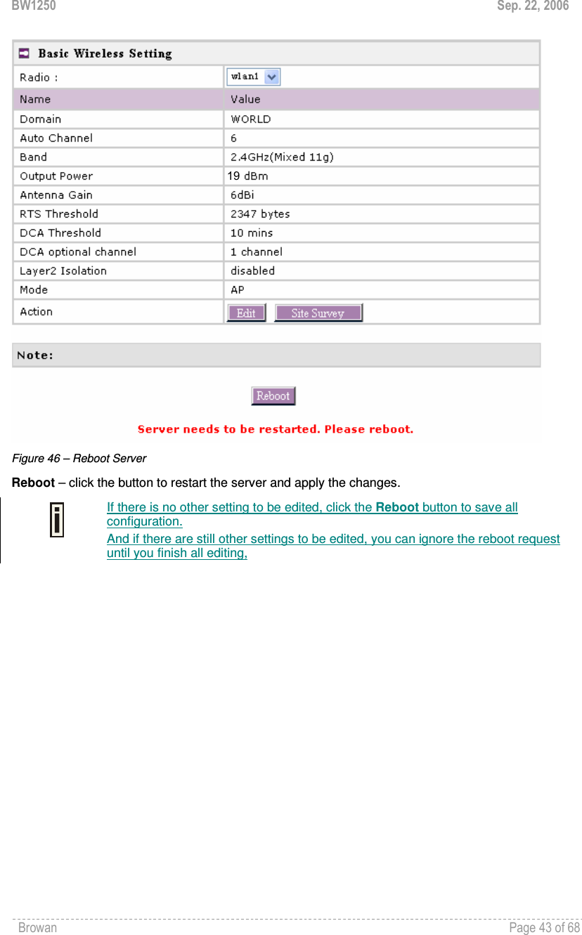
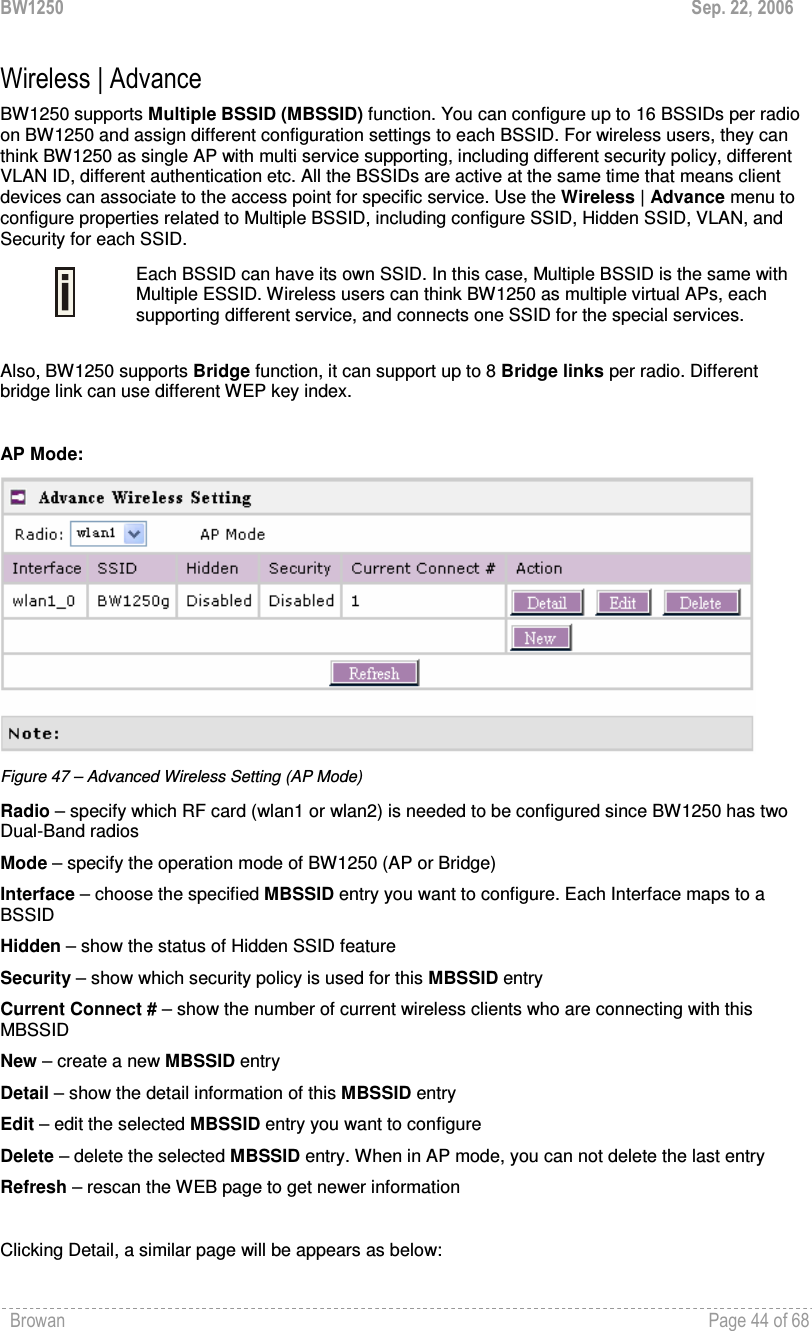
![BW1250 Sep. 22, 2006 Browan Page 29 of 68 Gateway – enter the gateway IP for wireless clients. WINS Address (Windows Internet Naming Service) – specify server IP address if it is available on the network [dots and digits]. Lease Time – specify the IP address lease interval in seconds [1-1000000]. Domain – specify the DHCP domain name [optional, 1-128 sting]. DNS address – specify the DNS server’s IP address [in digits and dots notation]. DNS secondary address – specify the secondary DNS server’s IP address [in digits and dots notation]. Change status or leave in the default state if no editing is necessary and click the Save button. Figure 24 – Apply or Discard DHCP server Settings The DHCP server settings will be automatically adjusted to match the network interface settings. The Gateway of DHCP server settings must be same with the Gateway of BW1250 For each change of settings, the BW1250 needs to be restarted to apply all settings changes when clicking Apply Changes. Request for reboot server appears:](https://usermanual.wiki/GemTek-Technology/A950806AG/User-Guide-720874-Page-30.png)
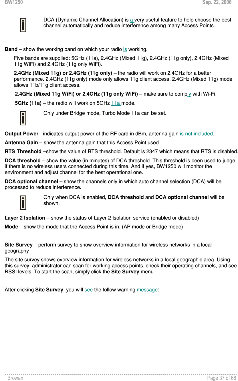
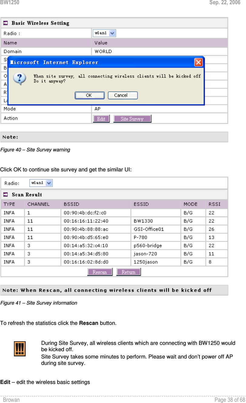
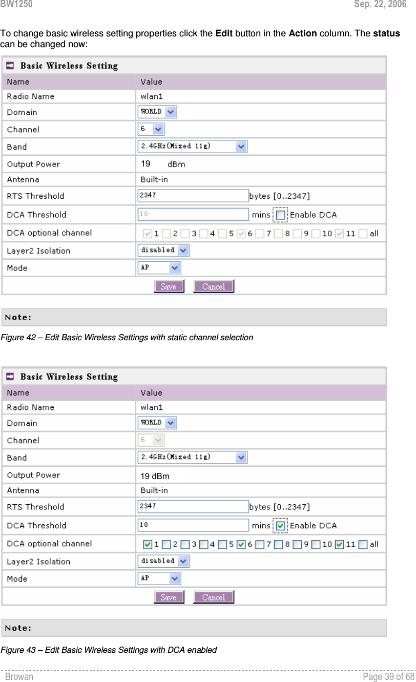
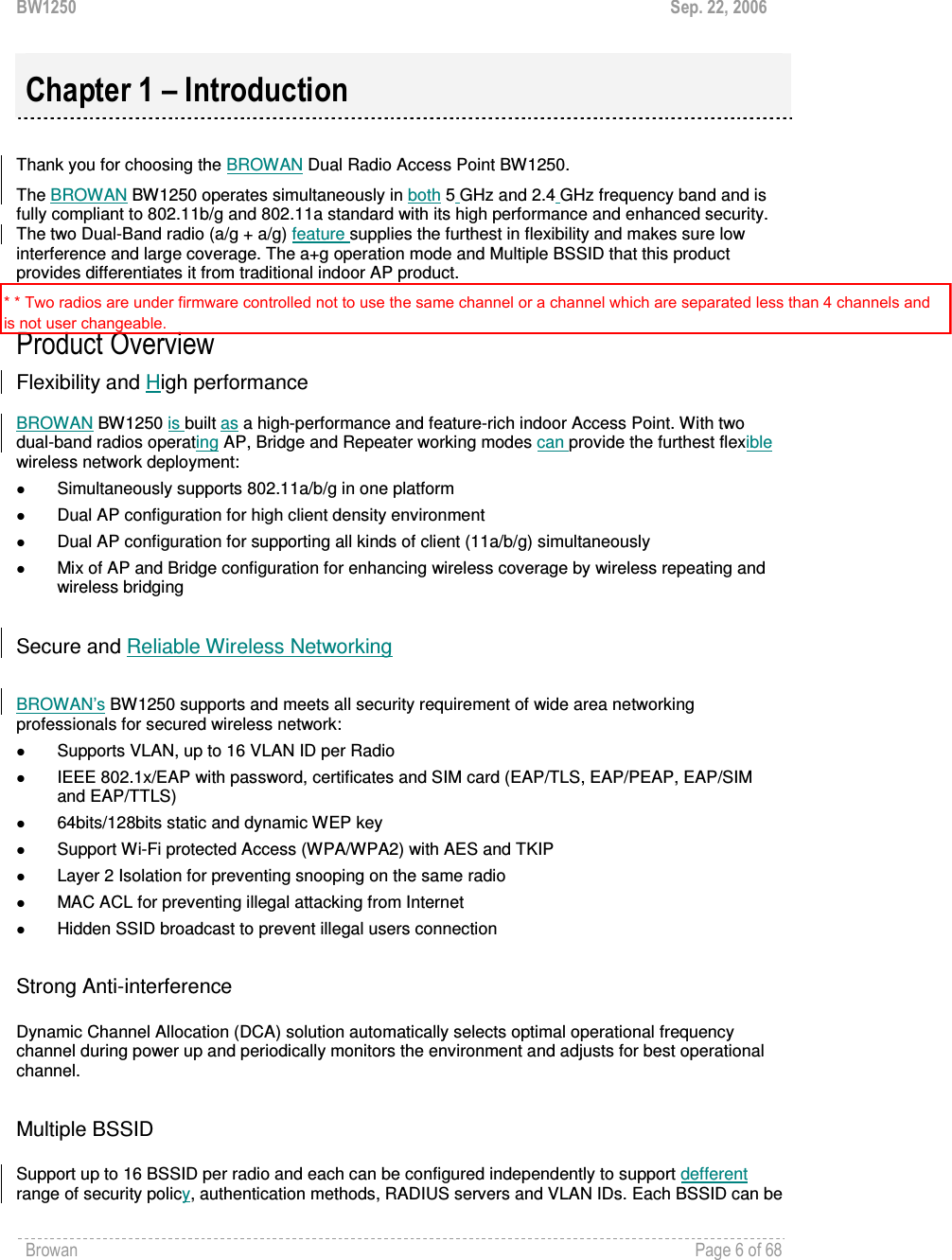
![BW1250 Sep. 22, 2006 Browan Page 40 of 68 Radio Name – specify which wireless interface of BW1250 is shown Domain – select the regulatory domain according to your country The full frequency range of the 2.4 GHz or 5 GHz is not permitted for use in all countries. Depending on your selection of regulatory domains, the available frequency channels will vary. Before changing radio settings manually, make sure that your settings comply with government regulations. At all times, it ‘s the responsibility of the end-user to ensure that the installation complies with local radio regulations. Refer to the Appendix: C) Regulatory Domain/Channels. Channels – select the channel that the access point will use to transmit and receive information. If one channel is defined, it acts as default channel. Channels list will vary depending on selected regulatory domain and selected band. Multiple frequency channels are used to avoid interference between two radios of this AP, and between nearby access points. If you wish to operate more than one access point in overlapping coverage areas, we recommend a distance of at least four channels between the chosen channels. For example, for three Access Points in close proximity choose channels 1, 6 and 11 for 11b/g or channels 36, 40 and 64 for 11a. Band – working band on which your radio is working. Five bands are supplied: 5GHz (11a), , 2.4GHz (Mixed 11g), 2.4GHz (11g only), 2.4GHz (Mixed 11g WiFi) and 2.4GHz (11g only WiFi). If 2.4GHz (Mixed 11g) or 2.4GHz (11g only) is selected, the radio will work on 2.4GHz for a better performance. 2.4GHz (11g only) mode only allows 11g client access. 2.4GHz (Mixed 11g) mode allows 11b/11g client access. 2.4GHz (Mixed 11g WiFi) or 2.4GHz (11g only WiFi) can make sure to compatible with Wi-Fi. If 5GHz (11a) is selected, the radio will work on 5GHz 11a mode. Only under Bridge mode, Turbo Mode 11a can be set. Output Power - indicates output power of the RF card in dBm, antenna gain is not included. Total Output Power (EIRP) = Antenna Gain + RF card output power The range of the EIRP varies with channel and regulatory domain. Antenna – show the type of Antenna. RTS Threshold – when set, this settings specifies the maximum packet size beyond which RTS/CTS mechanism is be invokes. The value range of this is [0 …2347]. Default is 2347 which means that RTS is disabled. Enable DCA – Enable or Disable DCA service. DCA can help to choose the best working channel automatically. And static channel selection will be forbidden if DCA is enabled. DCA(Dynamic Channel Allocation) solution automatically select the optimal operational frequency channel when power up and periodically monitors the environment and adjusts for the best operational frequency channel.](https://usermanual.wiki/GemTek-Technology/A950806AG/User-Guide-720874-Page-41.png)
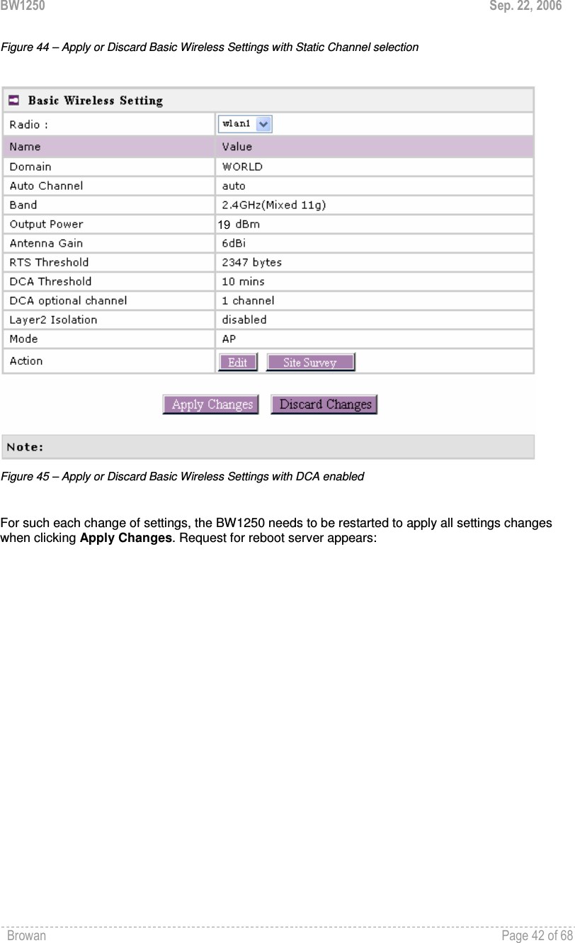
![BW1250 Sep. 22, 2006 Browan Page 41 of 68 DCA service is available only under 2.4GHz band. DCA threshold – specify the value (in minutes) of DCA threshold. This threshold is been used to judge if there is no wireless users connected during this time. And if yes, BW1250 will monitor the environment and adjust channel for the best operational one. If wireless network environment is stable which means auto channel selection needn’t do frequently, set a big value for DCA threshold to gain a stable wireless users’ connection. If wireless network environment changes continually, frequent auto channel selection is needed. So set a relative small value for DCA threshold to let channel change based on wireless environment. Wireless users will be kicked off when DCA is processing (site survey and new operational frequency channel takes effect). DCA optional channel – specify the channels only in which auto channel selection (DCA) will choose for reducing interference reference. Only when DCA is enabled, DCA threshold and DCA optional channel will be shown. Layer 2 Isolation – layer2 wireless client separation. Connected clients with user isolation function enabled cannot access each other directly. The clients are isolated from each other using their MAC addresses [enabled/disabled]. Mode – two modes are supplied: AP mode and Bridge mode. Change status or leave in the default state if no editing is necessary and click the Save button. 19](https://usermanual.wiki/GemTek-Technology/A950806AG/User-Guide-720874-Page-42.png)
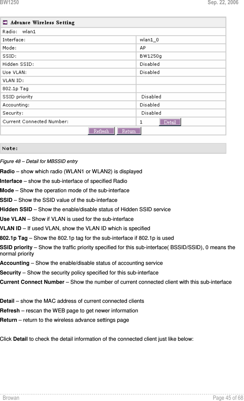
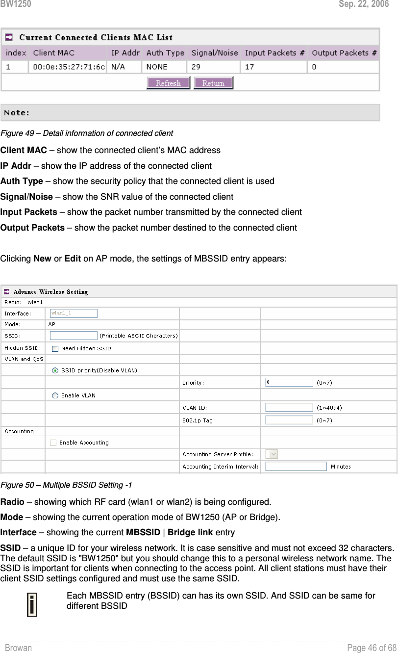
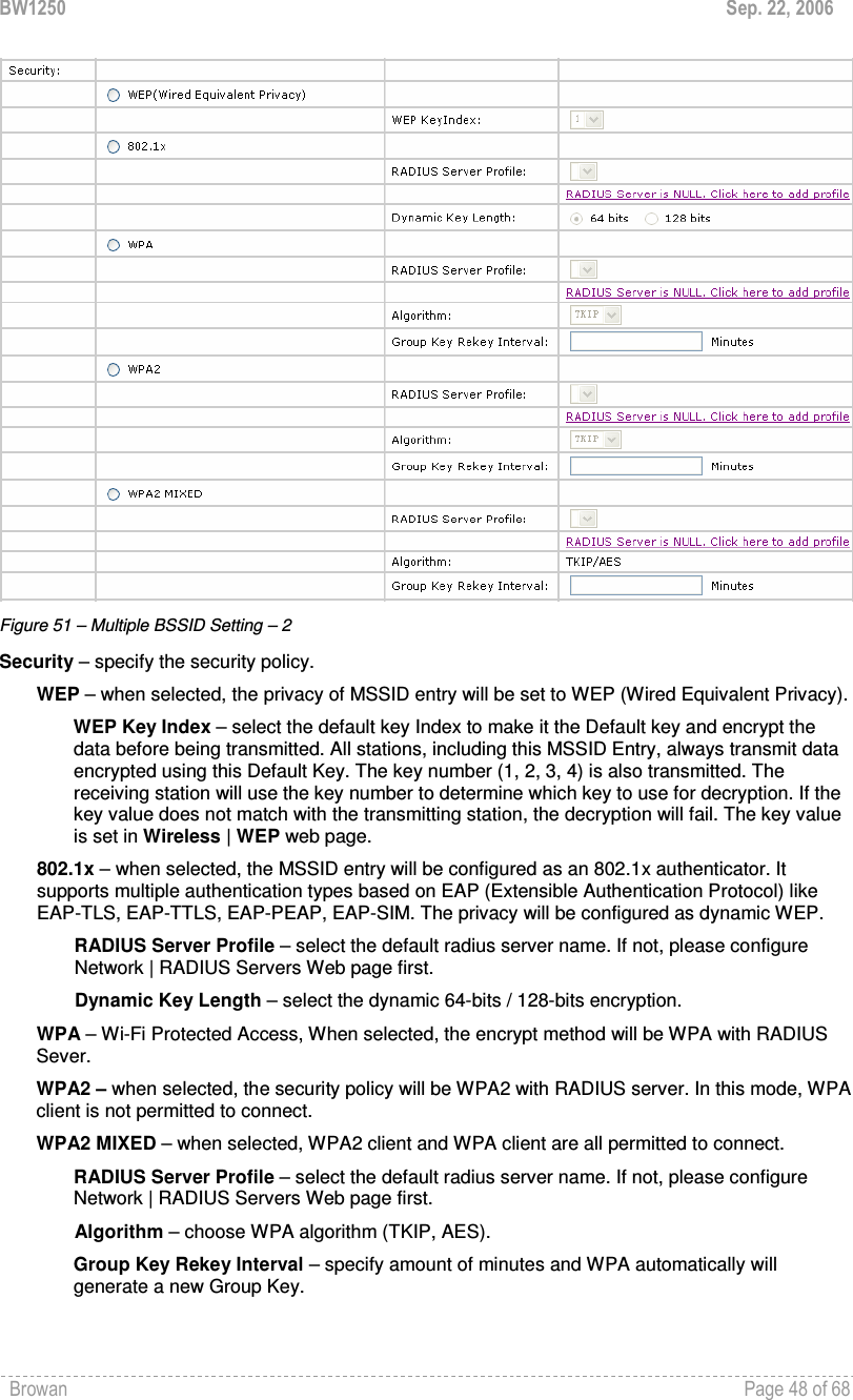
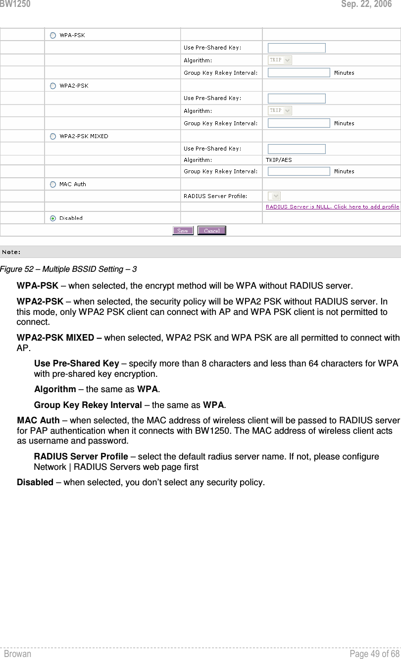
![BW1250 Sep. 22, 2006 Browan Page 47 of 68 Hidden SSID – when enabled, the SSID of this Interface is invisible in the networks list while scanning the available networks for wireless client (SSID is not broadcasted with its Beacons). When disabled, the AP’s SSID is visible in the available network list [enabled/disabled]. By default the Hidden SSID is disabled. VLAN and QoS – specify VLAN policy or QoS policy. Data priority is based on (B)SSID and is implemented by 802.11e EDCA or 802.1p tag. SSID priority (Disable VLAN) – specify the data priority, which is implemented according to 802.11e EDCA and makes sure the wireless downlink QoS. This priority is based on (B)SSID, which means different BSSID can have different data priority and the data of the same BSSID has the same priority. This data priority only makes sure the priority of downlink (from AP to wireless client). 8 levels priorities are supplied. 1, 2, 0, 3, 4, 5, 6, 7 is from lowest priority to highest priority. And if no special QoS is needed, leave priority to default (0). 0 means normal priority. Enable VLAN – when enabled, the outgoing packets from this SSID device will be tagged with VLAN ID and 802.1p tag (If have). VLAN ID – configure VLAN ID for each Multiple SSID devices. Valid numbers are from 1 to 4094. 802.1p Tag – configure 802.1p Tag for remote APC’s or Router’s QoS uses. Valid numbers are from 0 to 7. VLAN ID and 802.1p tag must cooperate with remote Router or APC. Accounting – Control the status of accounting service Enable Accounting – enable or disable the accounting service. Accounting service only can be enabled when the security policy using RADIUS server is chosen. The security policies using RADIUS server include 802.1x, WPA, WPA2, WPA2 MIXED and MAC auth. Accounting Server Profile – specify which RADIUS server is used for accounting service. If not have any RADIUS server, please configure Network | RADIUS Servers Web UI first. Accounting Interim Interval – specify the value (in minutes) which is used for interim-accounting interval, which is helpful for statistics.](https://usermanual.wiki/GemTek-Technology/A950806AG/User-Guide-720874-Page-48.png)
![BW1250 Sep. 22, 2006 Browan Page 56 of 68 System System | Security Use the System | Security service to configure the name and password administrator: Figure 63 – system security settings User Name – administrator username for access to BW1250 (e.g. web interface, CLI mode) [1-32 symbols, spaces not allowed]. Old Password – old password value. New Password – new password value used for user authentication in the system [4-8 characters, spaces not allowed]. Confirm Password – re-enter the new password to verify its accuracy. Save – click to save new administrator settings. Default administrator logon settings are: User Name: admin Password: admin01 Password length is from 4 to 8 characters. After filling in the right Old password and the New Password, clicking the Save button for taking effect immediately. After clicking Save button, the below UI will be shown to notify that the new password setting has been taken place:](https://usermanual.wiki/GemTek-Technology/A950806AG/User-Guide-720874-Page-57.png)
![BW1250 Sep. 22, 2006 Browan Page 57 of 68 Figure 64 – system security settings save and take effect successfully System | SNMP SNMP is the standard protocol that regulates network management over the Internet. To communicate with SNMP manager you must set up the same SNMP communities and identifiers on both ends: manager and agent. Use the System | SNMP menu to change current SNMP configuration. Figure 65 – SNMP settings Readonly community – community name is used in SNMP version 1 and version 2c. Read-only (public) community allows reading values, but denies any attempt to change values [1-32 all ASCII printable characters, no spaces]. Readwrite community – community name is used in SNMP version 1 and version 2c. Read-write (private) community allows to read and (where possible) change values [1-32 all ASCII printable characters, no spaces]. Default Trap community – the default SNMP community name used for traps without specified communities. The default community by most systems is "public". The community string must match the community string used by the SNMP network management system (NMS) [1-32 all ASCII printable characters, no spaces]. Trap Configuration Table:](https://usermanual.wiki/GemTek-Technology/A950806AG/User-Guide-720874-Page-58.png)
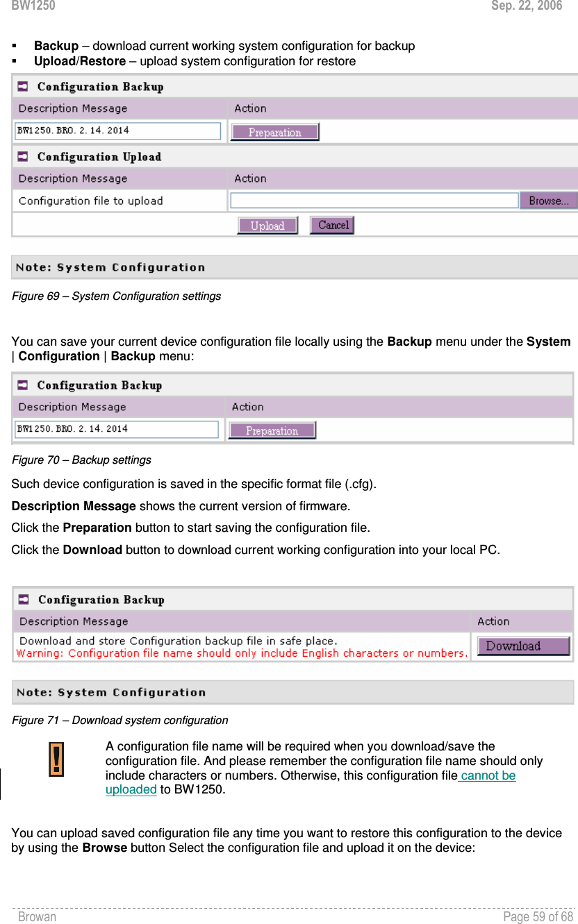
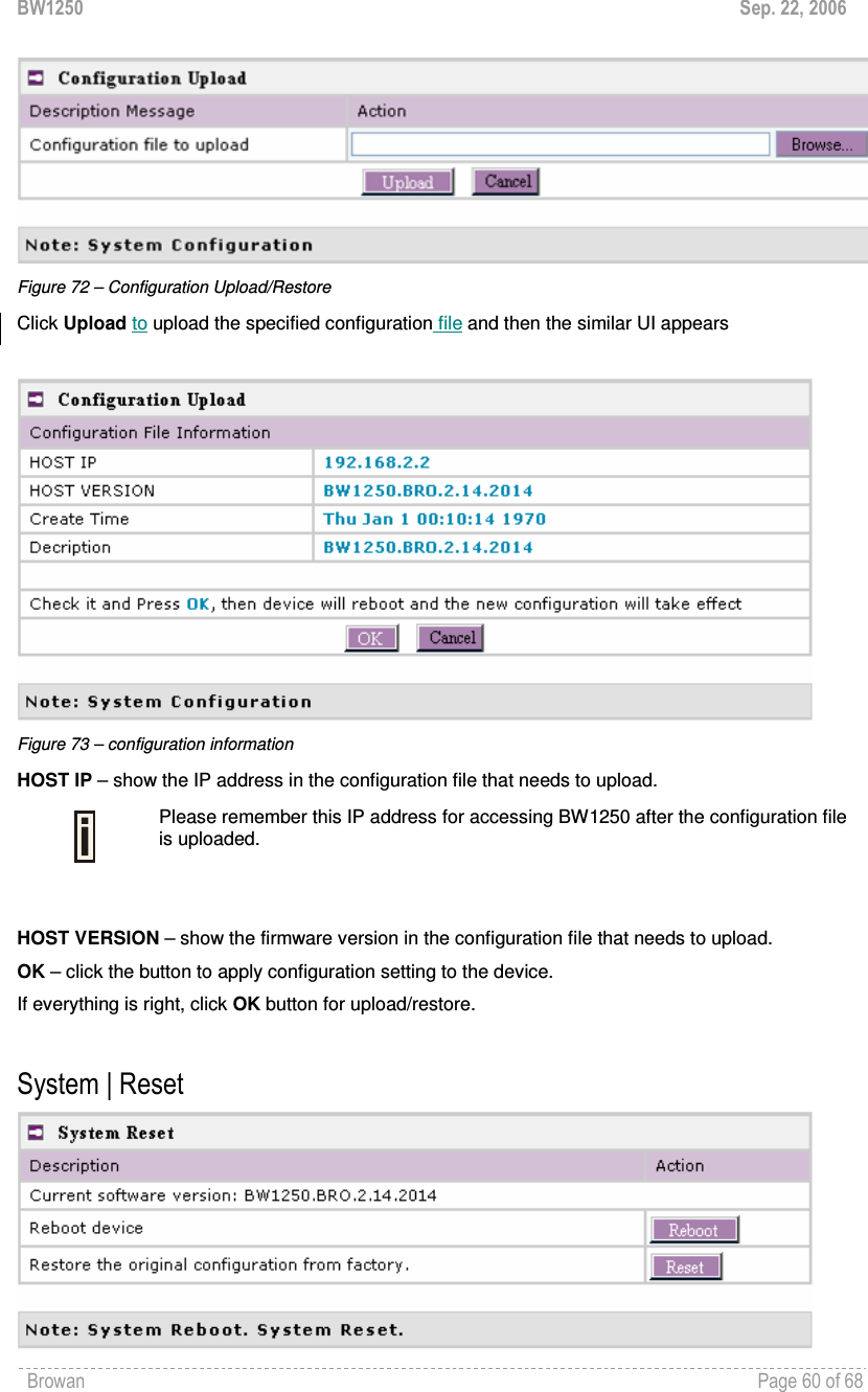
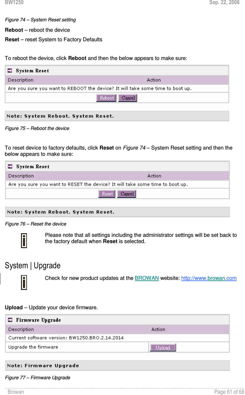
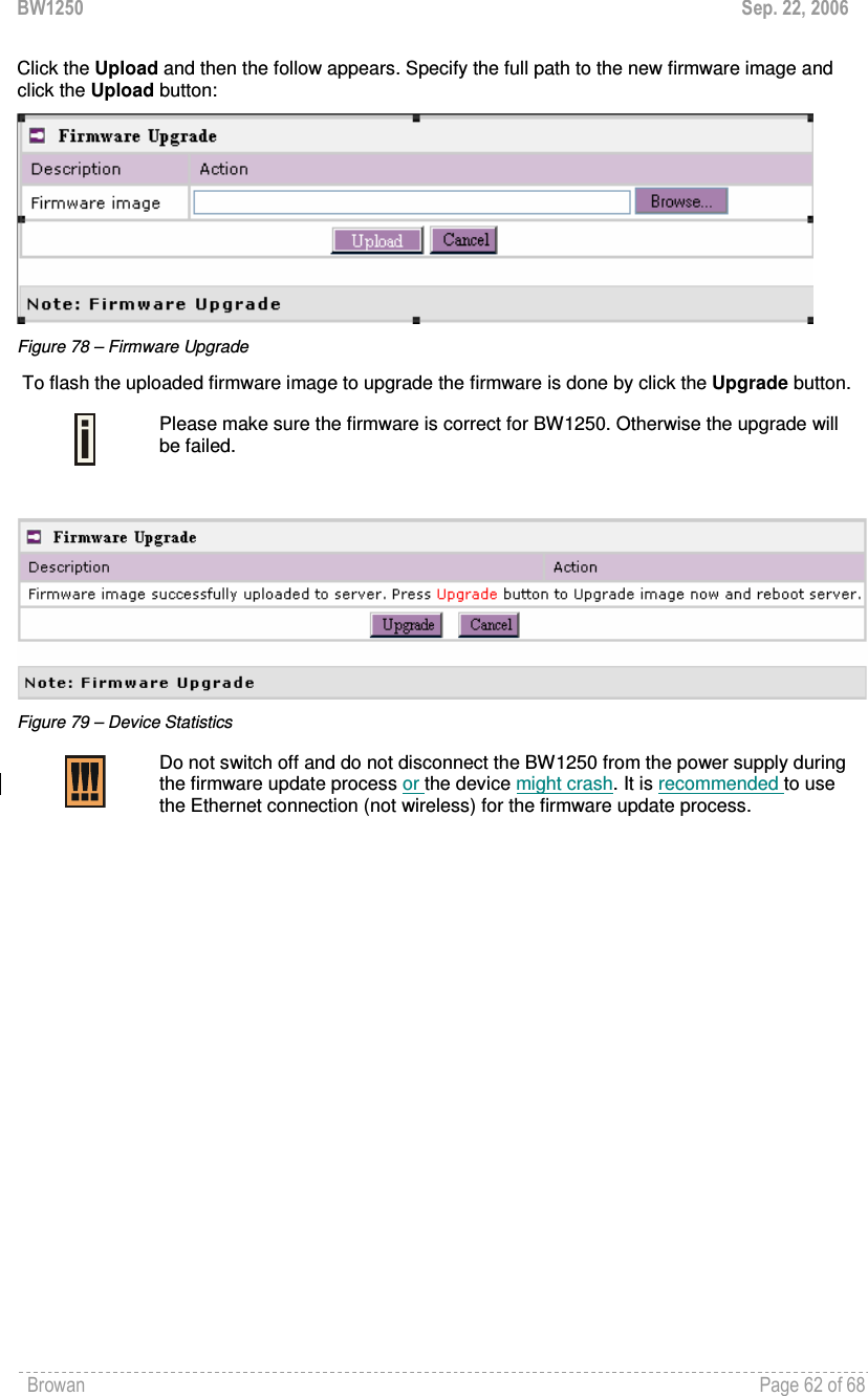
![BW1250 Sep. 22, 2006 Browan Page 58 of 68 You can configure your SNMP agent to send SNMP Traps (and/or inform notifications) under the defined host (SNMP manager) and community name (optional). Figure 66 – SNMP Trap table settings Click Add to add a new SNMP manager or Delete to delete a specific SNMP manager. Clicking Add: Figure 67 – Add SNMP Trap Host IP – enter SNMP manager IP address [dots and digits]. Host Port – enter the port number the trap messages should be send through [number]. Trap Type – select trap message type [v1/v2/inform]. Community – specify the community name at a SNMP trap message. This community will be used in trap messages to authenticate the SNMP manager. If not defined, the default trap community name will be used (specified in the SNMP table) [1-32 all ASCII printable characters, no spaces]. Save – save all current settings Cancel – restore the last settings System | Telnet Use System | Telnet menu to manage the telnet/SSH service of your BW1250. Figure 68 – System Configuration settings Telnet Service – Enable or disable telnet service of BW1250 SSH Service – Enable or disable SSH service of BW1250. The default of these two services are all Enabled. The current IETF SSH (SSHv2) is supported for security of accessing BW1250 via telnet/CLISH. System | Configuration Use the System | Configuration menu to configure such system utilities:](https://usermanual.wiki/GemTek-Technology/A950806AG/User-Guide-720874-Page-59.png)