GemTek Technology AP930621G 54 Mb Hotspot-in-a-Box User Manual Title
Gemtek Technology Co., Ltd. 54 Mb Hotspot-in-a-Box Title
UserManual.wiki
>
GemTek Technology
>
AP930621G User Manual
>
User Manual Part 1
Contents
1.
User Manual Part 1
2.
Users Manual Part 2
User Manual Part 1
Navigation menu
Upload a User Manual
Namespaces
Wiki Guide
HTML
PDF
Info
Views
User Manual
Discussion / Help
Navigation
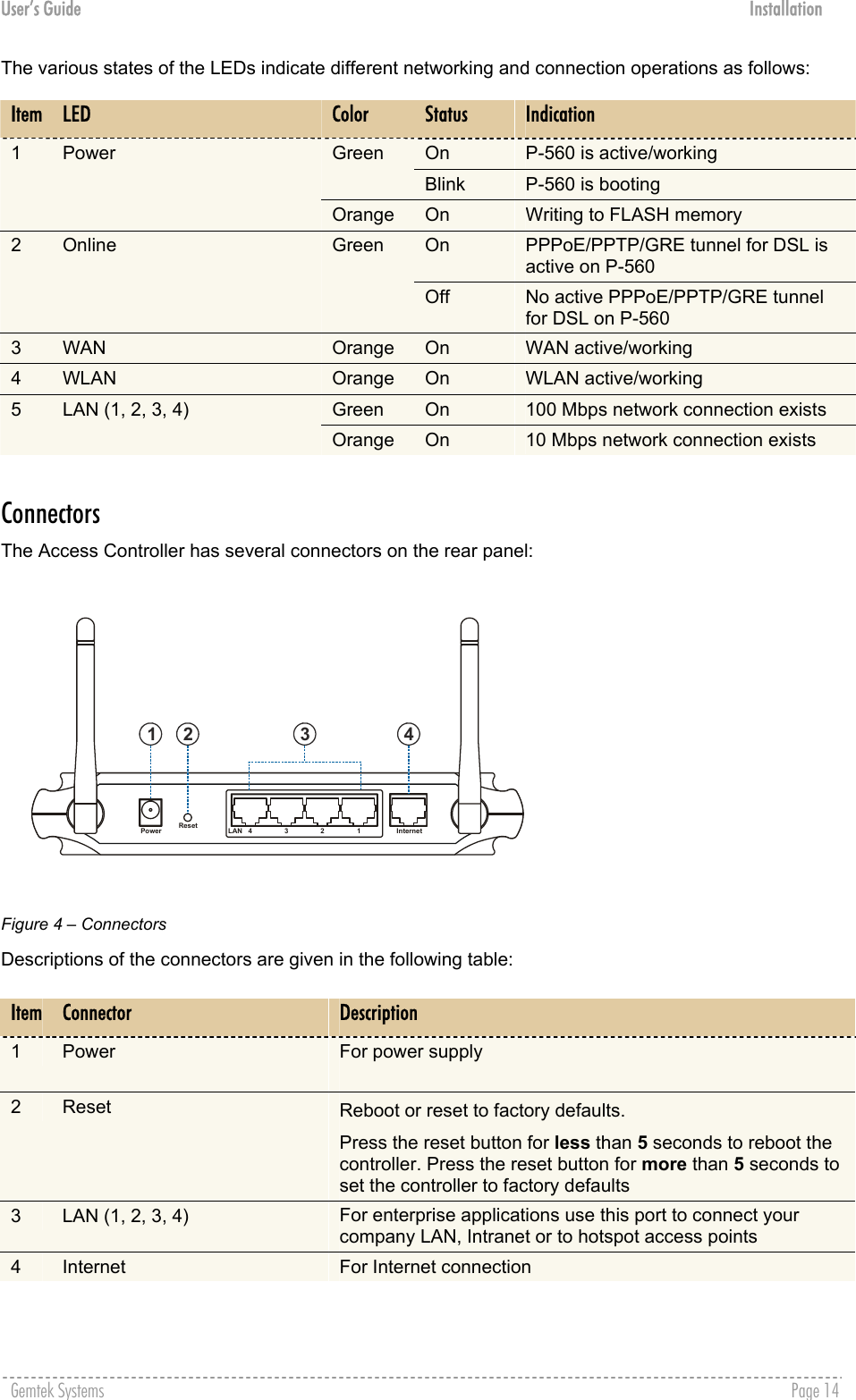
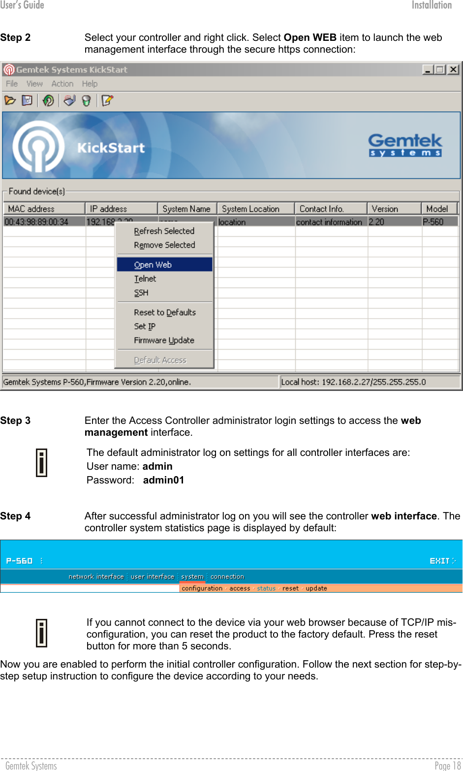
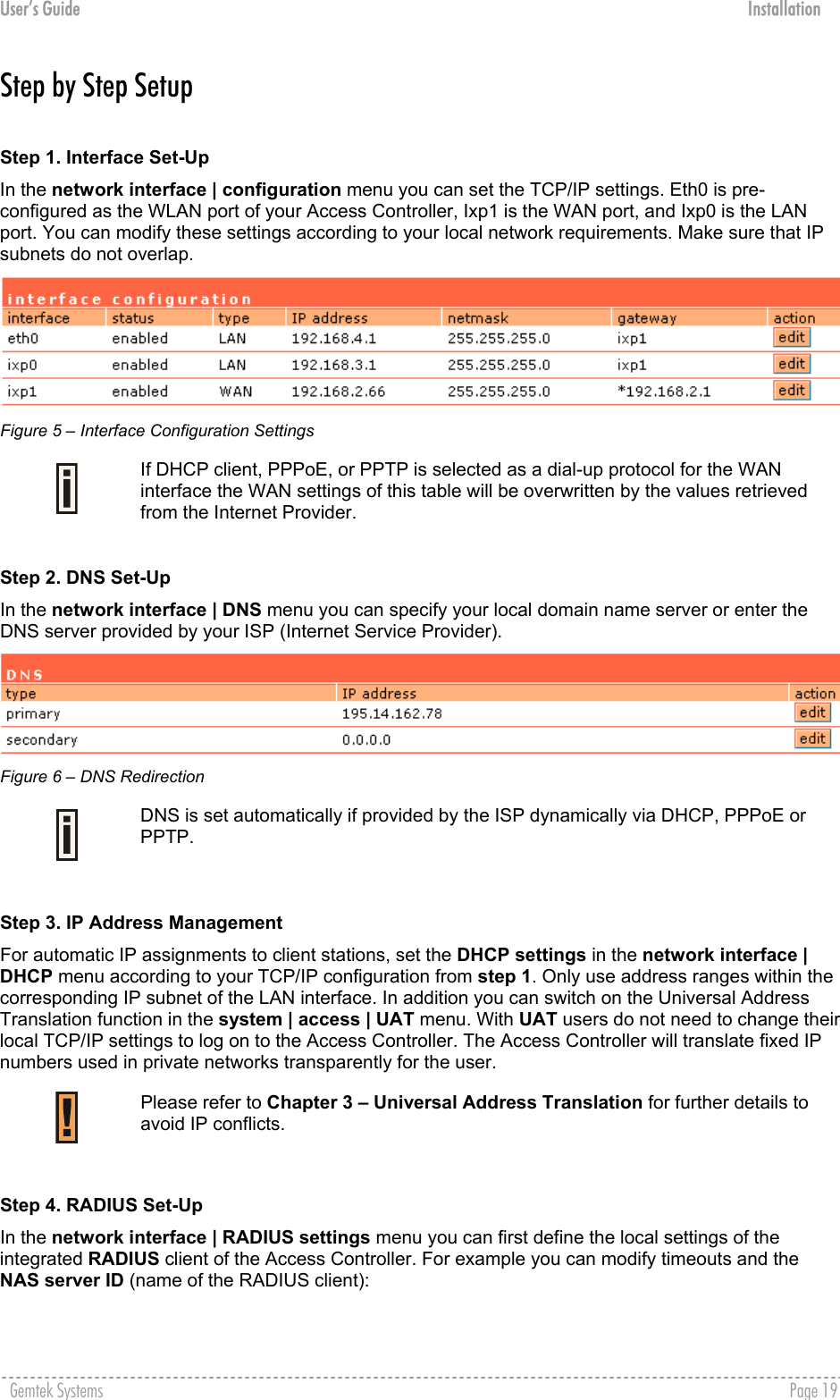
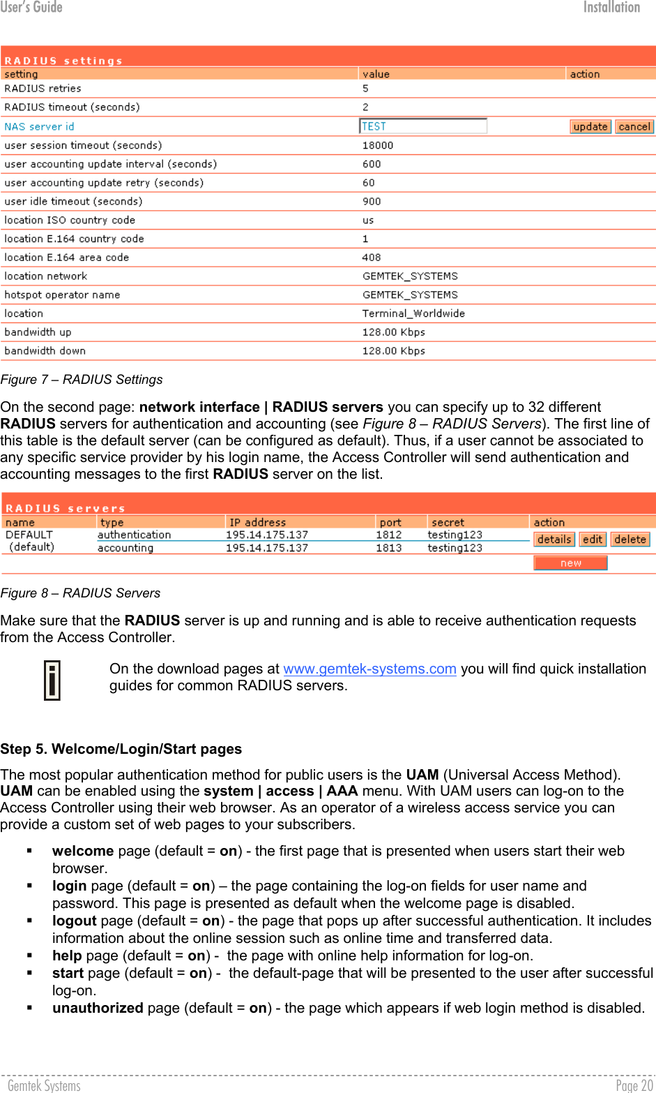
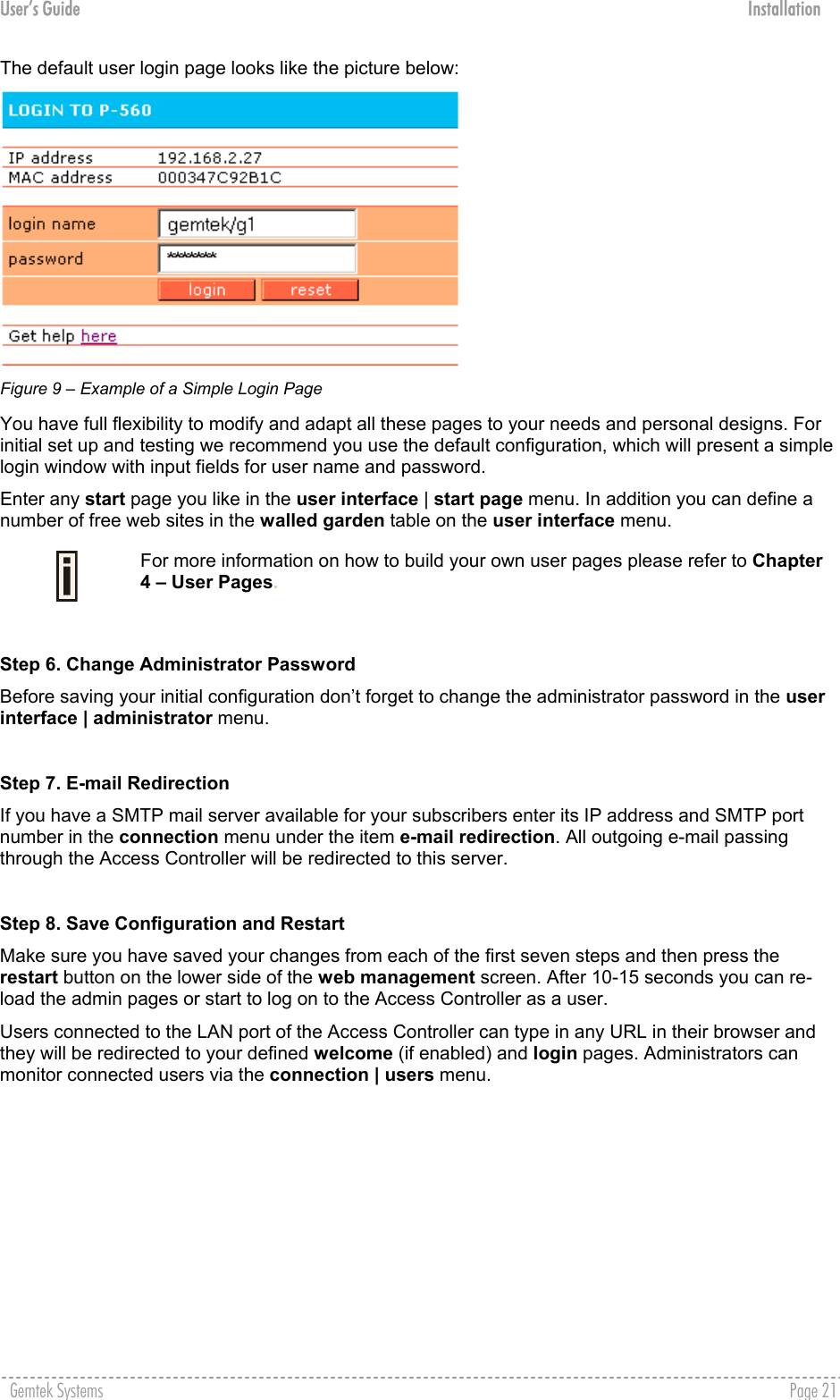
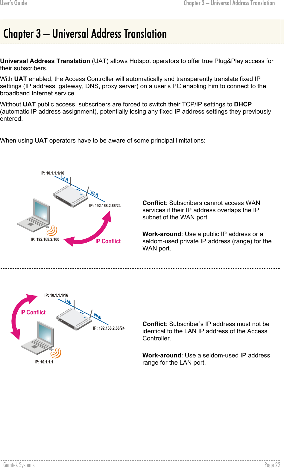
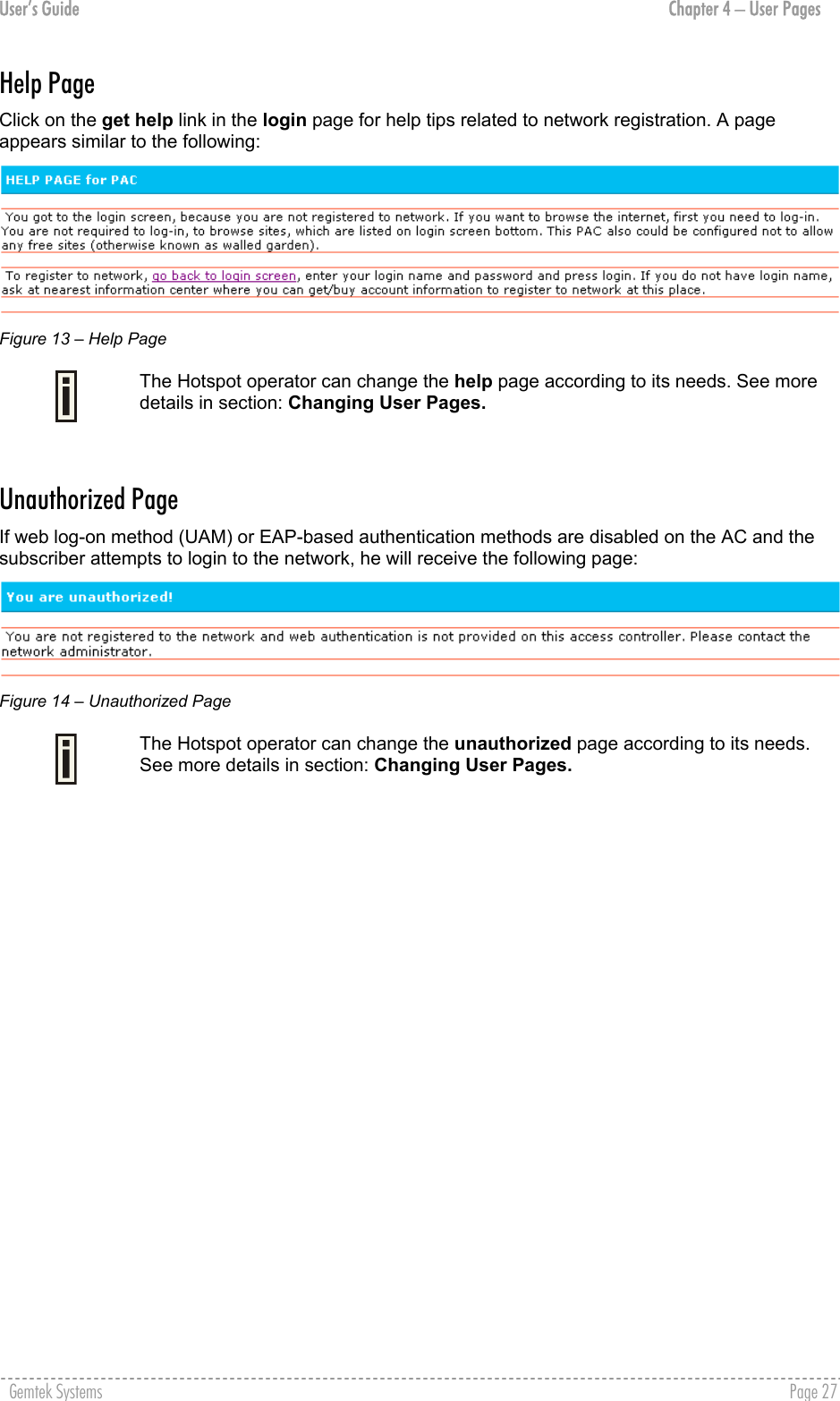
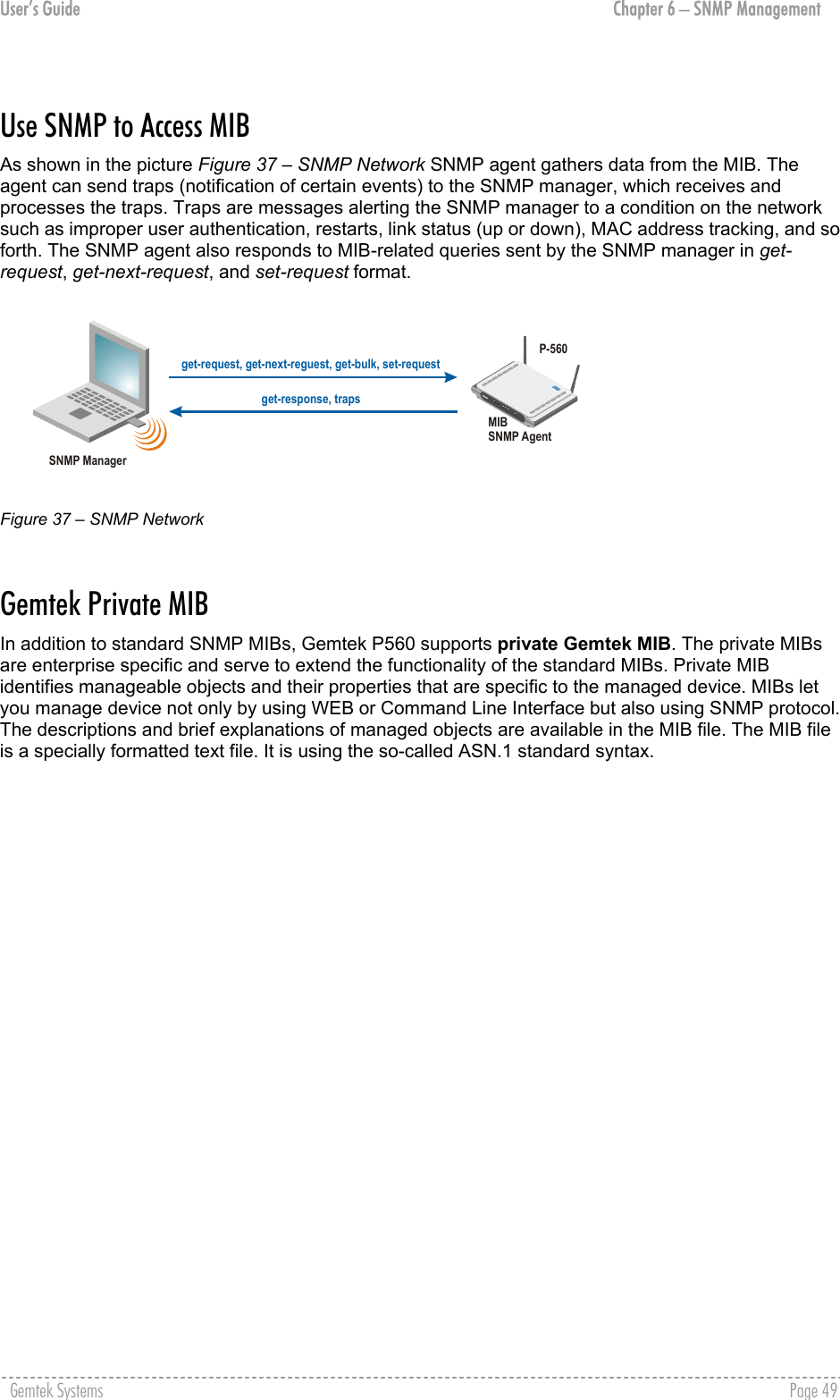
![User’s Guide About this Guide About this Guide Purpose This document provides information and procedures on hardware installation, setup, configuration, and management of the Gemtek Systems high performance 56Mb Hotspot-in-a-Box model P-560. The P-560 is a highly integrated Access Controller for public access areas. We will call it AC later in the manual. Prerequisite Skills and Knowledge To use this document effectively, you should have a working knowledge of Local Area Networking (LAN) concepts and wireless Internet access infrastructures. In addition, you should be familiar with the following: Hardware installers should have a working knowledge of basic electronics and mechanical assembly, and should understand related local building codes. Network administrators should have a solid understanding of software installation procedures for network operating systems under Microsoft Windows 95, 98, Millennium, 2000, NT, and Windows XP and general networking operations and troubleshooting knowledge. Conventions Used in this Document The following typographic conventions and symbols are used throughout this document: Very important information. Failure to observe this may result in damage. Important information that should be observed. Additional information that may be helpful but which is not required. bold Menu commands, buttons and input fields are displayed in bold code File names, directory names, form names, and system-generated output such as error messages are displayed in constant-width type <value> Placeholder for certain values, e.g. user inputs [value] Input field format, limitations, and/or restrictions. Help Us to Improve this Document! If you should encounter mistakes in this document or want to provide comments to improve the manual please send e-mail directly to: manuals@gemtek-systems.com Gemtek Systems Technical Support If you encounter problems when installing or using this product, please consult the Gemtek Systems website at www.gemtek-systems.com for: Direct contact to the Gemtek Systems support centers. Frequently Asked Questions (FAQ). Download area for the latest software, user documentation and product updates. Gemtek Systems Page 7](https://usermanual.wiki/GemTek-Technology/AP930621G.User-Manual-Part-1/User-Guide-451086-Page-7.png)
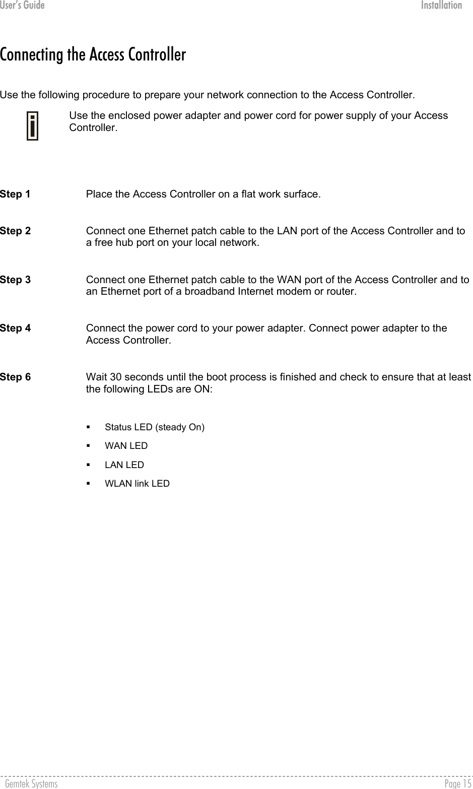
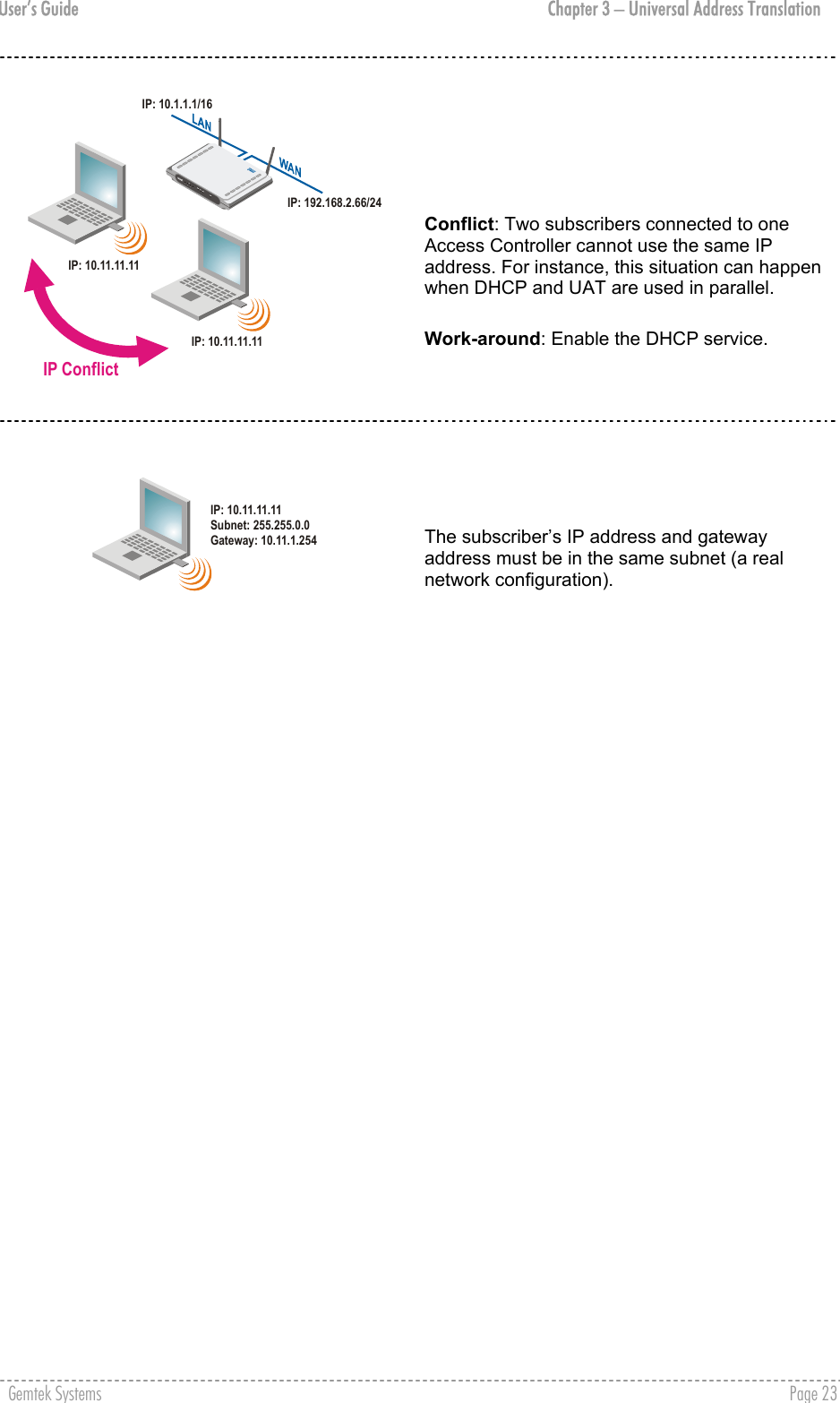
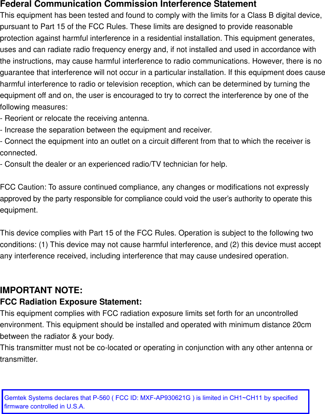
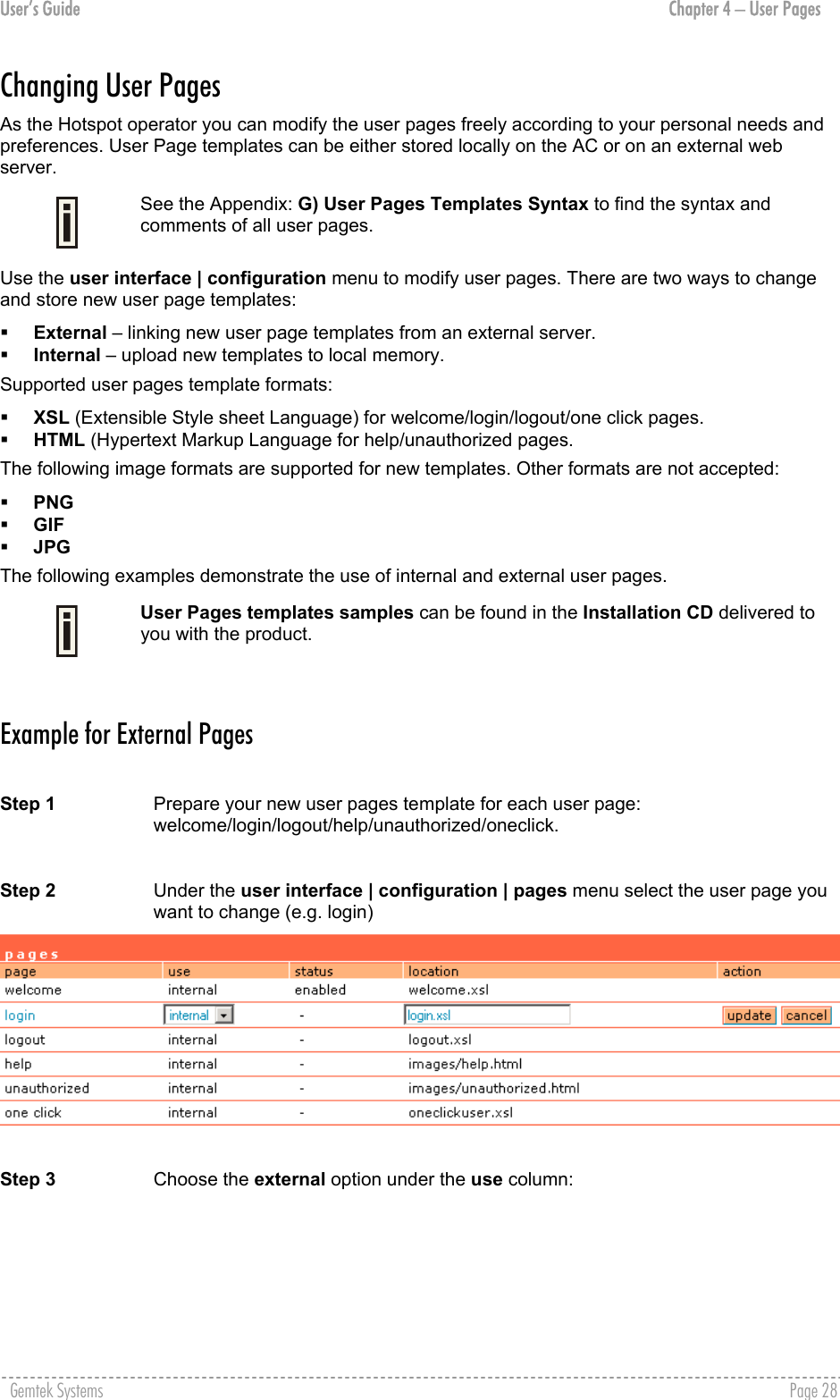
![User’s Guide Chapter 4 – User Pages Logout Page Make sure the JavaScript is enabled on your Web browser; otherwise you will not receive the logout page. The Logout page contains the detailed subscriber’s session information and provides function for logging out of the network: Figure 12 – Logout Page Detailed AC subscriber’s session information includes: User – subscriber’s login name. User IP – subscriber’s logical network name (IP address). MAC Address – subscriber’s physical network address. Session time – subscriber’s session time from client log on in format: [hours: minutes: seconds]. Input/Output bytes – subscriber’s session input and output statistics in bytes. Input/Output bytes left – session input and output bytes left for subscriber limited from RADIUS [in B, KB, MB, GB and unlimited]. Total bytes left – session total (input and output) bytes left for subscriber limited form RADIUS [in B, KB, MB, GB and unlimited]. Session time left – session time left in format: [hours: minutes: seconds]. Bandwidth downstream/upstream – available upstream and downstream bandwidth for subscriber limited from RADIUS [in bps]. Logout button – click the button to logout from the network. The log-out pop-up window closes. Refresh button – click the button to refresh the subscriber session information. The Hotspot operator can change the logout page interface according to its needs. See more details in section: Changing User Pages. All session details are further accessible via the operator XML interface. Gemtek Systems Page 26](https://usermanual.wiki/GemTek-Technology/AP930621G.User-Manual-Part-1/User-Guide-451086-Page-26.png)
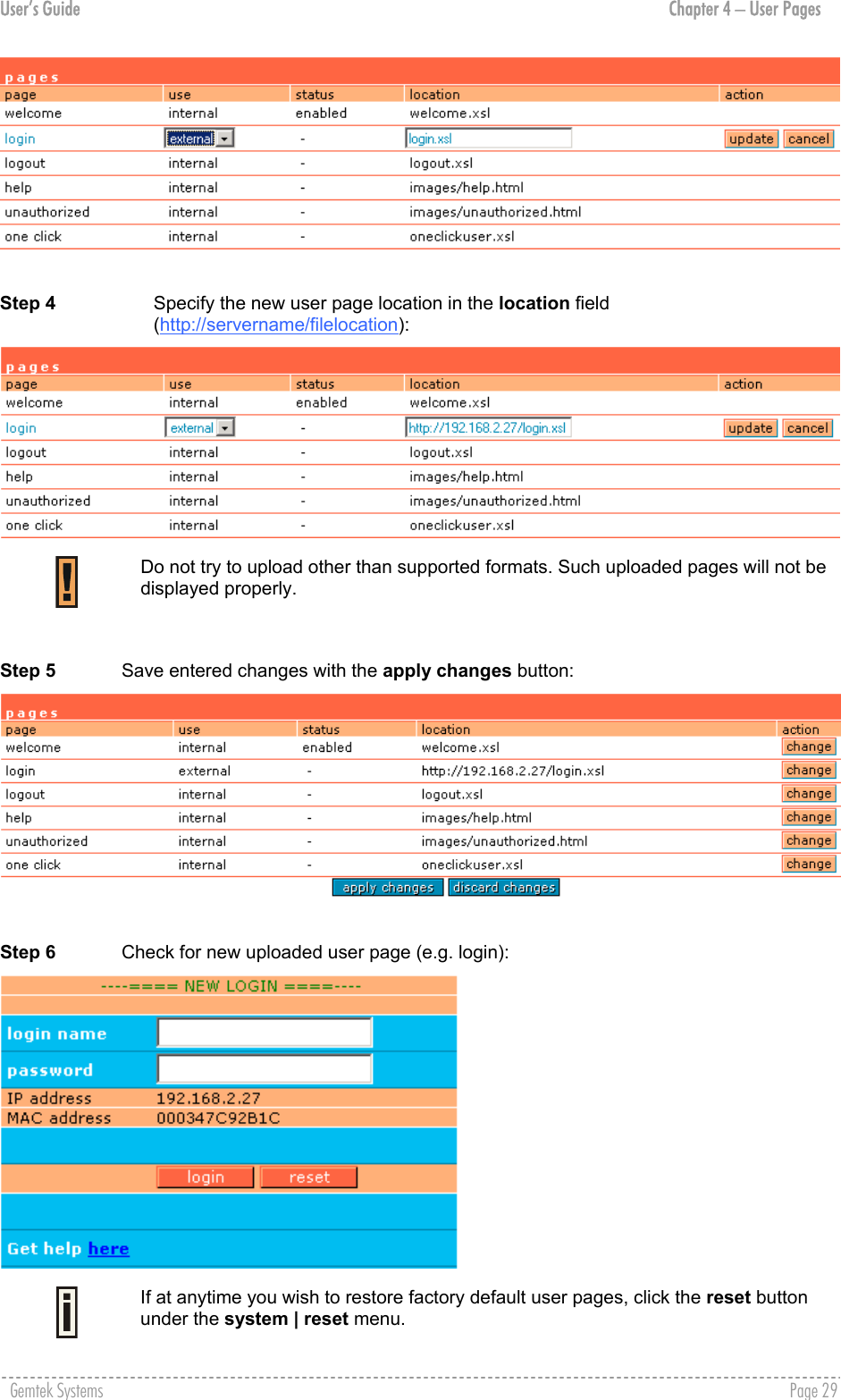

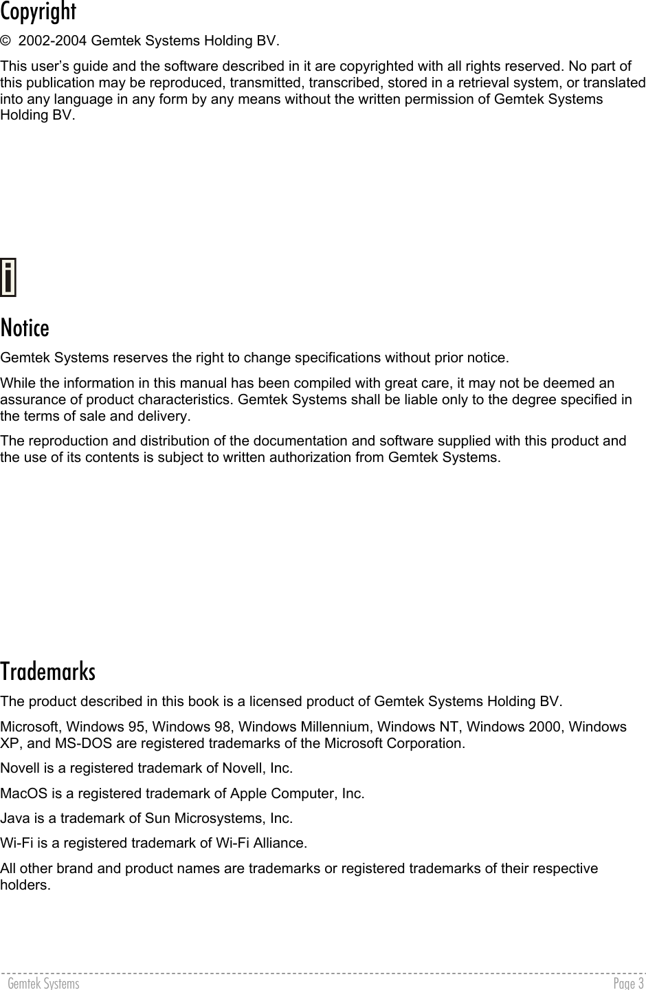
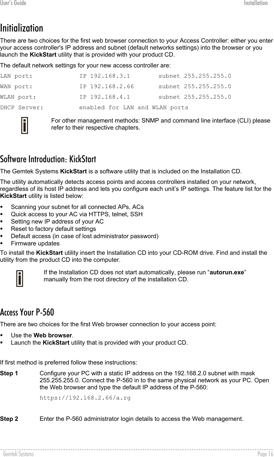
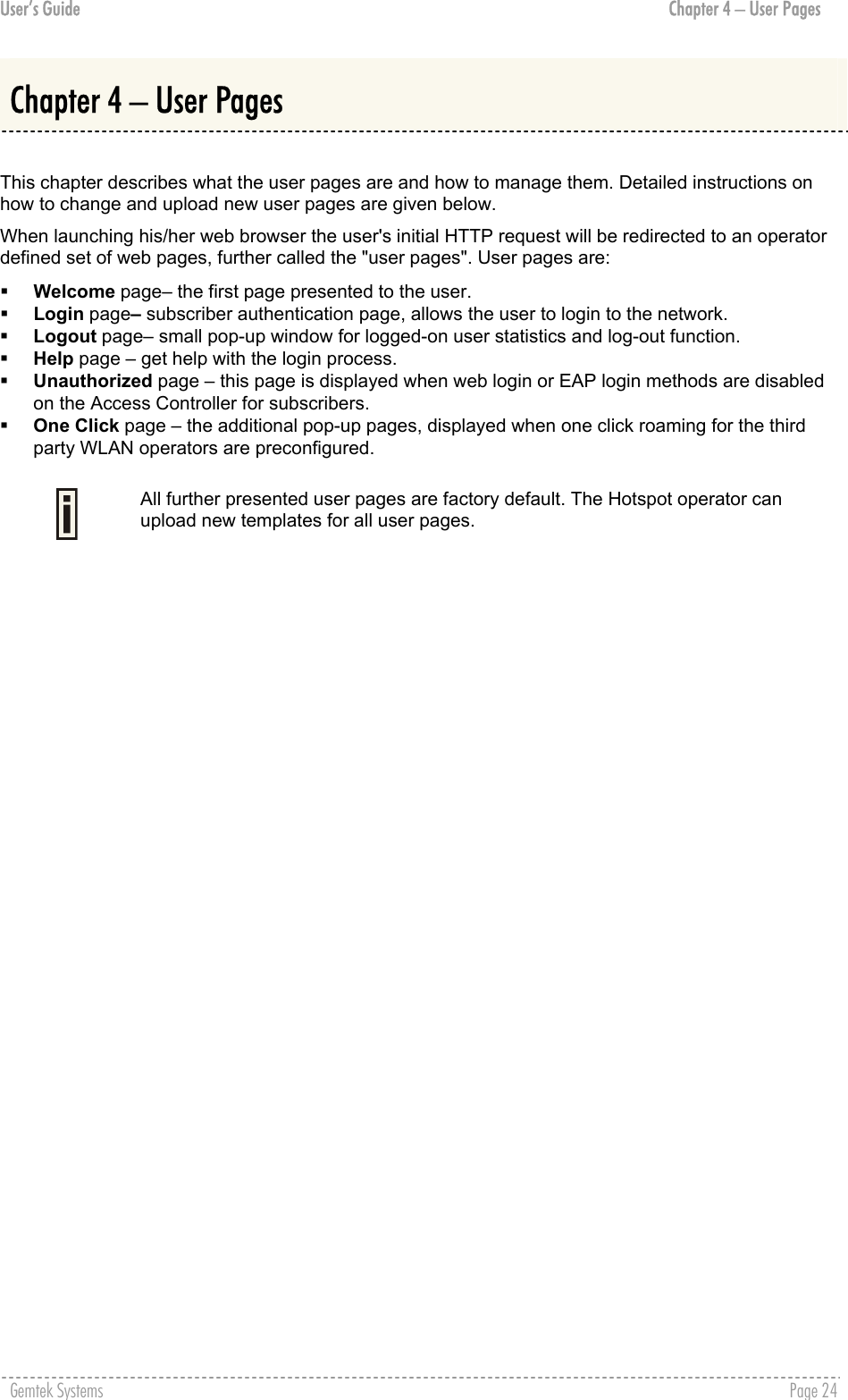
![User’s Guide Chapter 5 – Command Line Interface connection ? Figure 20 – Connection Commands Network Network is a category of commands that configures controller interface settings, DNS, DHCP, UAT and RADIUS settings. A full list of all available network commands/subcommands and its parameters is available in the Appendix section D) CLI Commands and Parameters. The network commands themselves contain several subcommands and the subcommands again contain several parameters. In general, network command usage is as follows: network <command> <subcommand1> <subcommand2> [-parameter] <value> To get a list of all available commands in the configure category, type: network ? Figure 21 – Network Commands List To get a list of all-available subcommands for a specific command, type: network <command> ?, (e.g. network radius ?) All available subcommands for radius are displayed: Figure 22 – Configure Network (1) Specific command contains several subcommands: network <command> <subcommand1> ?, (e.g. network radius servers ?) All available subcommands are displayed: Gemtek Systems Page 41](https://usermanual.wiki/GemTek-Technology/AP930621G.User-Manual-Part-1/User-Guide-451086-Page-41.png)
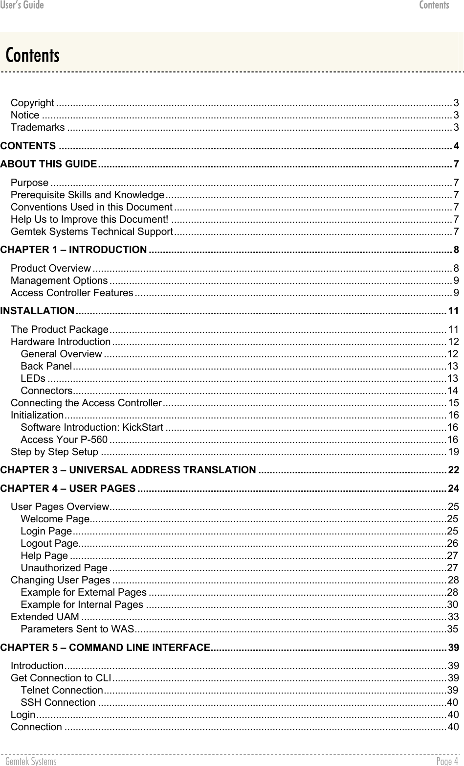
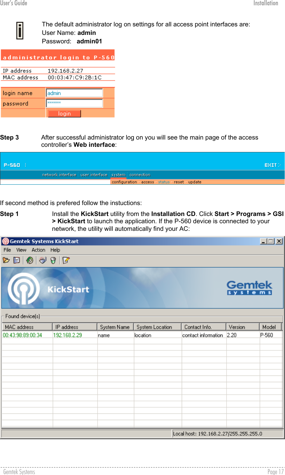
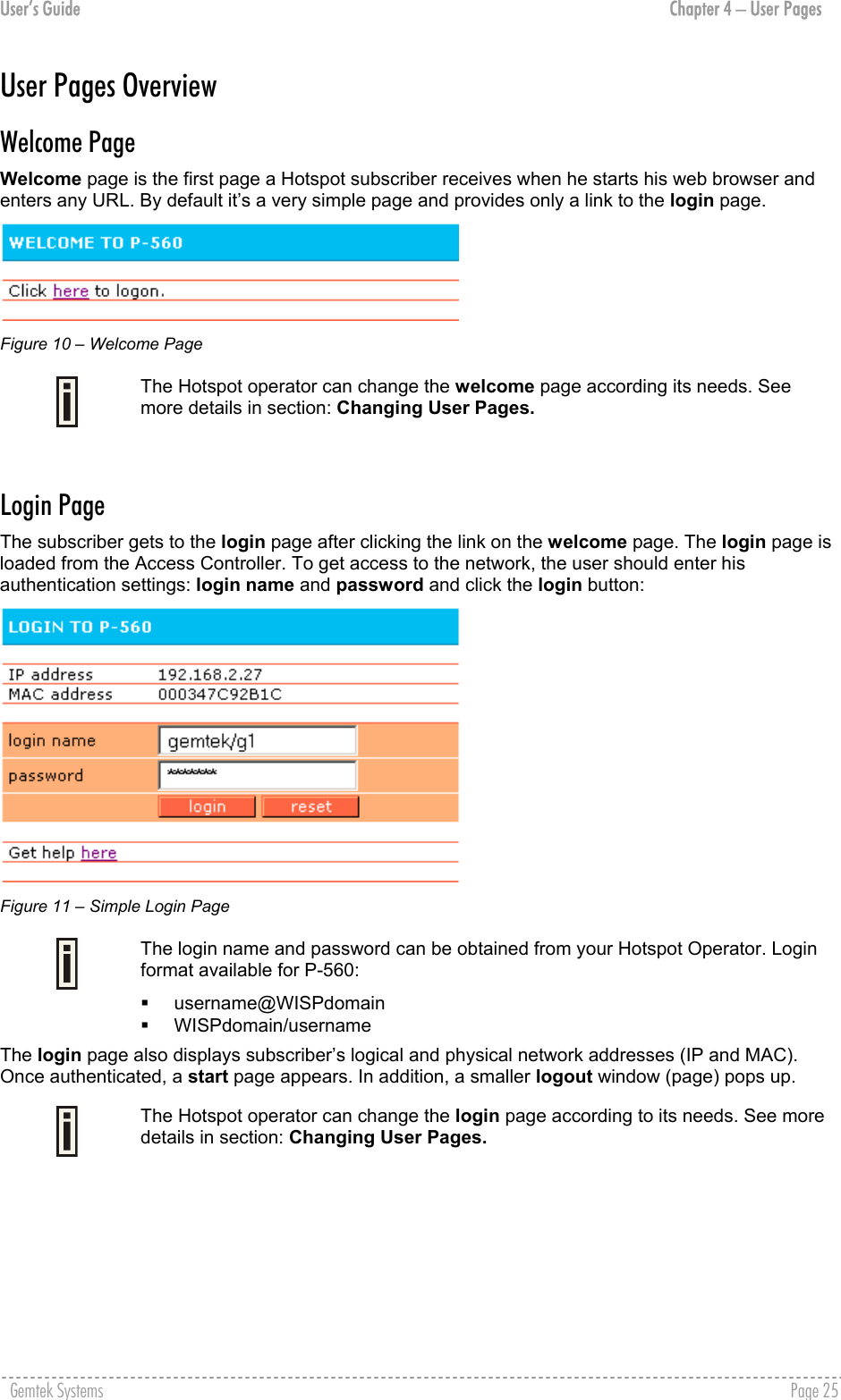
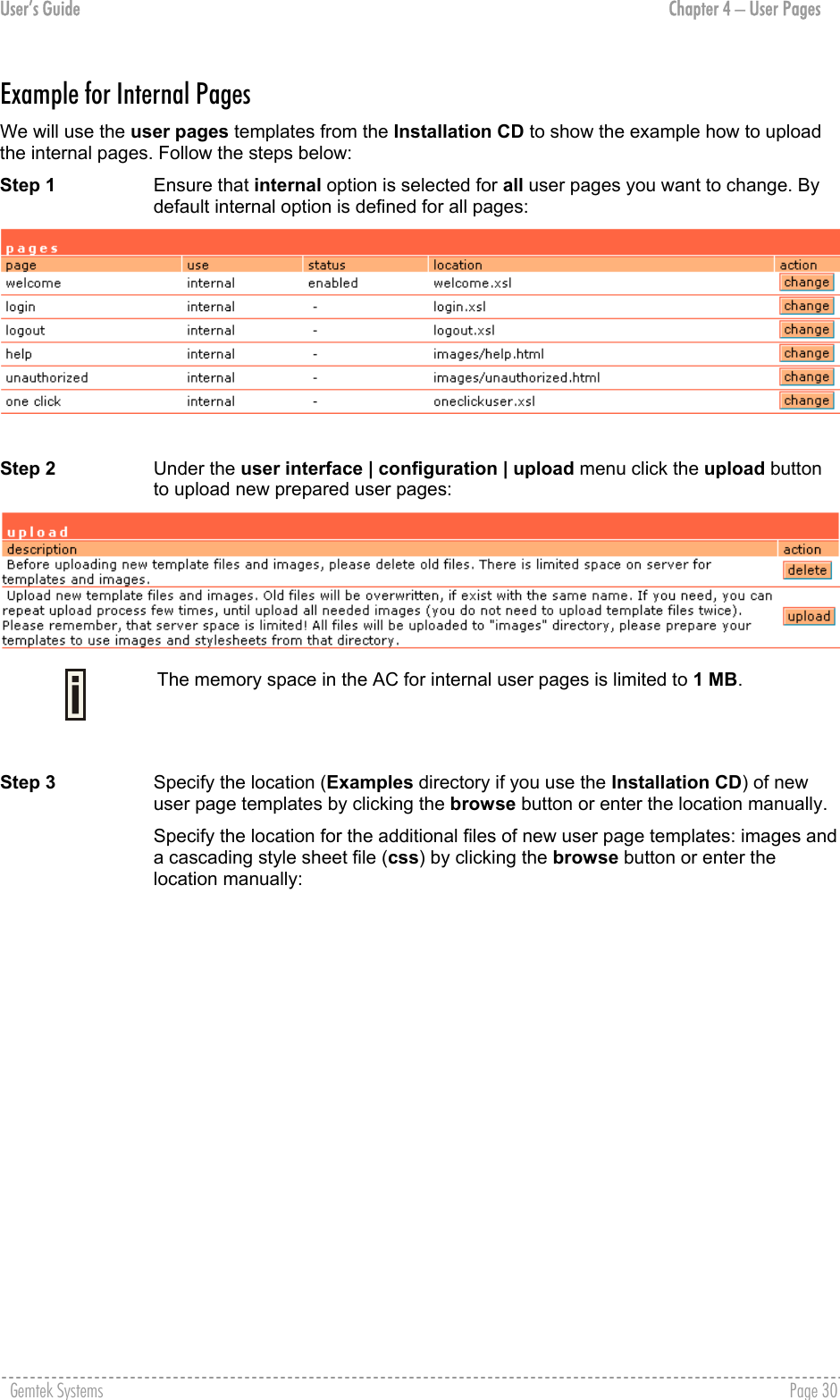
![User’s Guide Chapter 5 – Command Line Interface Figure 23 – Configure Network (2) To get a list for available parameters on selected subcommand, type: network <command> <subcommand1> <subcommand2> ?, (e.g. network radius servers accounting ?) All available parameters on entered subcommand are displayed: Figure 24 – Configure Network (3) To configure the desired controller interface setting, type all required parameters with values and subcommands: network <command> <subcommand1> <subcommand2> [-parameter] <value> (e.g. network radius servers accounting 1 –a 127.0.0.2 –p 1814 –s testing111), where parameters are as follows: -a – RADIUS server IP address used for RADIUS accounting -p – RADIUS server port number used for RADIUS accounting -s – Shared secret key for accounting. Figure 25 – Configure Network (4) If successful, a message regarding the successful completion is displayed; otherwise, an error message is displayed. In some cases, entered commands without parameters display current controller configuration or settings: network <command> <subcommad1> <subcommad2>, (e.g. radius servers accounting), displays available RADIUS servers and its settings list (in this case, the RADIUS accounting server which is already updated): Figure 26 – Configure Network (5) Gemtek Systems Page 42](https://usermanual.wiki/GemTek-Technology/AP930621G.User-Manual-Part-1/User-Guide-451086-Page-42.png)
![User’s Guide Chapter 5 – Command Line Interface Wireless Wireless is a category of commands that configures controller basic and advanced wireless interface settings, access control list (ACL) and WDS. A full list of all available wireless commands/subcommands and its parameters is available in the Appendix section: D) CLI Commands and Parameters. The wireless commands themselves contain several subcommands and the subcommands again contain several parameters. In general, wireless command usage is as follows: wireless <command> <subcommand1> [-parameter] <value> To get a list of all available commands in the configure category, type: wireless ? Figure 27 –Wireless Commands List To get a list of all-available subcommands for a specific command, type: wireless <command> ?, (e.g. wireless basic ?) All available subcommands for radius are displayed: Figure 28 – Configure Wireless Basic To configure the desired controller interface setting, type all required parameters with values and subcommands. Use the samples from previous section. Gemtek Systems Page 43](https://usermanual.wiki/GemTek-Technology/AP930621G.User-Manual-Part-1/User-Guide-451086-Page-43.png)
![User’s Guide Chapter 5 – Command Line Interface User User is a category of commands that configures controller interface settings, affecting the user’s interface: redirection URL, free sites (walled garden), system management access, administrator login/password. A full list of all available user commands/subcommands and their parameters is available in the Appendix section: D) CLI Commands and Parameters. In general, the user command usage is as follows: user <command> <subcommand1> <subcommand2> [-parameter] <value> To get the full list of the user commands, type: user ? Figure 29 – User Commands List To get a list of all-available subcommands for a specific command, type: user <command> ?, (e.g. user walled_garden ?) All available subcommands for walled garden (free sites) are displayed: Figure 30 – Configure User Interface (1) To configure selected user interface settings, type: User <command> <subcommand1> <subcommand2> [-parameter] <value>, (e.g. user walled_garden url A -u www.gemtek.system.com -s gemtek system site), where parameters are as follows: A – action: add URL -u – define URL address -s – define URL description, visible for user: Figure 31 – Configure User Interface (2) If successful, a message regarding the successful completion is displayed; otherwise, an error message is displayed. Gemtek Systems Page 44](https://usermanual.wiki/GemTek-Technology/AP930621G.User-Manual-Part-1/User-Guide-451086-Page-44.png)
![User’s Guide Chapter 5 – Command Line Interface Status Status is a category of commands that’s displays: General devices status (model, firmware version, uptime, memory) All interface network settings (IP address/netmask, MAC address, gateway, RX/TX statistics) Currently running services (DHCP, routes, port forward, telnet, SNMP, UAT, ..). A full list of all available status commands/subcommands and their parameters is available in the Appendix section: D) CLI Commands and Parameters. In general the status command usage is as follows: Status <command> To get the full list of the status commands, type: status ? Figure 32 – System Status Commands List To get the general device status information, type: status device : Figure 33 – Device Status Here you can find the current firmware version of your AC. This is important information for support requests and for preparing firmware uploads. System System is a category of commands that configures access to controller (telnet, AAA methods, L2 isolation, SNMP, UAT) and configuration: clock, NTP, syslog, trace. A list of all available system commands/subcommands and their parameters are available in the Appendix section: D) CLI Commands and Parameters. In general, the system command usage is as follows: system <command> <subcommand1> <subcommand2> [-parameter] <value> To get the full list of the system commands, type: system ? Gemtek Systems Page 45](https://usermanual.wiki/GemTek-Technology/AP930621G.User-Manual-Part-1/User-Guide-451086-Page-45.png)
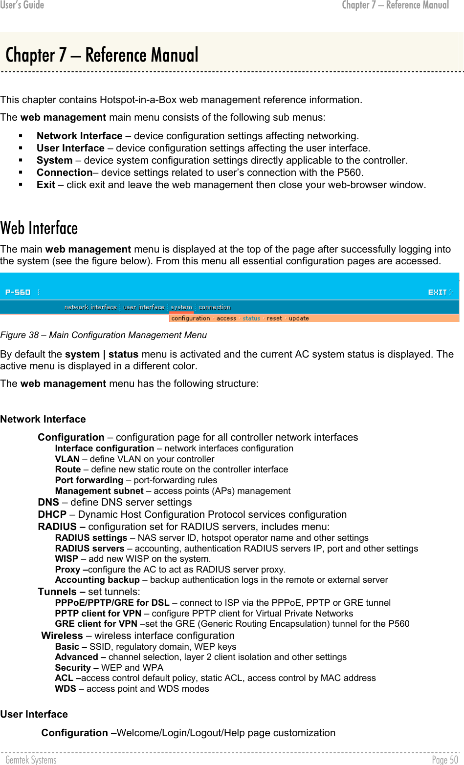
![User’s Guide Chapter 7 – Reference Manual Network Interface Network Interface | Configuration | Interface Configuration The interfaces eth0 and ixp0 on 2.21 firmware are bridged therefore they will be displayed as one eth0. The screen shots in this manual will not match with ones on your device. The Hotspot-in-a-Box contains up to three multi-purpose network interfaces: eth0, ixp0 and ixp1. These interfaces can be configured to work as either local area network (LAN) or wide area network (WAN) interfaces for Access Points. LAN is used to connect hubs, switches, Access Points and subscribers. The WAN port connects to the Internet or the service provider’s backbone network. All these interfaces are listed in the interface configuration page. All network interfaces available in the Hotspot-in-a-Box are shown in the following table: Figure 39 – Interface Configuration Table To change network interface configuration properties click the edit button in the action column. The status can be changed now: Figure 40 – Edit Interface Configuration Settings part.1 Interface - standard interface name. This name cannot be edited and is assigned by the operating system during startup. Interface name cannot be changed because the hardware drivers define it. Status – select the status of interface: [enabled/disabled]. Do not disable the interface through which you are connected to the P-560. Disabling such interface will lose your connection to the device. Type – network type cannot be changed. There are two possible networking types: LAN – interface is used as local area network (LAN) gateway, and is connected to a LAN; WAN – interface is used to access the ISP network; Change status or leave in the default state if no editing is necessary and click the continue button. Then the following parameters can be changed: Figure 41 – Edit Interface Configuration Settings part.2 IP Address – specify new interface IP address [in digits and dots notation, e.g. 192.168.5.1]. Gemtek Systems Page 52](https://usermanual.wiki/GemTek-Technology/AP930621G.User-Manual-Part-1/User-Guide-451086-Page-52.png)
![User’s Guide Chapter 7 – Reference Manual IP address of each interface should be from a different subnet; otherwise, you will receive an error message. Netmask – specify the subnet mask [[0-255].[0-255].[0-255].[0-255]].These numbers are a binary mask of the IP address, which defines IP address order and the number of IP addresses in the subnet. Gateway – interface gateway. For LAN type interfaces, the gateway can only be defined as WAN interface gateway. The gateway of the WAN interface is usually the gateway router of the ISP or other WAN network. [Default gateway is marked with ‘*’]. Update – update old values with entered ones. The DHCP server settings will be automatically adjusted to match the new network settings. Figure 42 – Apply or Discard Interface Configuration Changes Apply changes – to save all changes made in the interface configuration table at once. Discard changes – restore all previous values. For such general changes as interface settings change, the Hotspot-in-a-Box server needs to be restarted. Request for restart server appears: Figure 43 – Restart Server Restart – Click the button to restart the server and apply the changes. Gemtek Systems Page 53](https://usermanual.wiki/GemTek-Technology/AP930621G.User-Manual-Part-1/User-Guide-451086-Page-53.png)
![User’s Guide Chapter 7 – Reference Manual Network Interface | Configuration | VLAN Up to 4094 VLANs can be created in the system. Virtual Local Area Networks (VLANs) are logical groupings of network resources. You can create your own VLANs on your AC using the network interface | configuration | VLAN menu. By default no VLANS are defined on the system: Figure 44 – VLAN To create a VLAN on the AC click the new button and enter following parameters: Figure 45 – Create New VLAN Interface – select interface for your VLAN network [eth0/ixp0]. Status – non-editable, by default is disabled. ID – assign ID for your VLAN network [1 to 4094]. Client devices that associate using the ID are grouped into this VLAN. Other VLAN settings cannot be changed. Click on the disabled link to continue specifying settings for your VLAN. The network interface configuration page is opened and VLAN settings are ready for editing: Figure 46 – Configure VLAN Status – enable/disable your VLAN network. Select [enable] and click the continue button to configure the VLAN settings: Figure 47 – Configure VLAN Type – cannot be edited, depends on selected interface for VLAN [ixp0/eth0]. IP Address – enter the network address of your VLAN [format: digits and dots]. Netmask – enter the netmask for your VLAN network [format: digits and dots]. Gateway – select gateway for VLAN network [default: ixp1]. Gemtek Systems Page 54](https://usermanual.wiki/GemTek-Technology/AP930621G.User-Manual-Part-1/User-Guide-451086-Page-54.png)
![User’s Guide Chapter 7 – Reference Manual Click the update and restart and apply changes to save your new VLAN. Check the interface | configuration | VLAN menu for new created VLAN: Figure 48 – Enable New VLAN Network Interface | Configuration | Route Under the network interface | configuration | route menu, static routes for the Ethernet interfaces can be set. By default no static routes are defined on the system: Figure 49 – Route A routing rule is defined by the target subnet (target IP address and subnet mask), interface and/or gateway where to route the target traffic. A data packet that is directed to the target network is routed to the specified AC interface or to another gateway router. To add a new static route for the system, click the new button under the action column and specify the following parameters: Figure 50 – Add New Route Status – set new static route status: [enabled/disabled]. Interface – choose device interface for the route: [eth0/ixp0/ixp1/vlan[n]]. Gateway – enter the gateway address for the route. 0.0.0.0 stands for the default gateway of the selected interface [IP address]. Target IP Address – enter network address or host IP to be routed to [IP address]. Netmask – enter the target network netmask [dots and digits]. Save – save the new route. Cancel – restore all previous values. Figure 51 – Save New Route Up to 255 static routes can be set between each interface. Gemtek Systems Page 55](https://usermanual.wiki/GemTek-Technology/AP930621G.User-Manual-Part-1/User-Guide-451086-Page-55.png)
![User’s Guide Chapter 7 – Reference Manual Network Interface | Configuration | Port Forwarding Port Forwarding is required when NAT is configured. NAT translates all internal addresses to one official IP address (WAN IP address). With port forwarding enabled it is possible to access internal services and workstations from the WAN interface. Port forwarding forwards TCP or UDP traffic trough the P560 controller’s local port to the specified remote port. Use the network interface | configuration | port forwarding menu to specify such a port forwarding rule. By default no port forwards are defined on the controller: Figure 52 – Port Forwarding Rules Click the new button to add a port-forwarding rule: Figure 53 – Add Port Forwarding Rule. Status – select status: [enabled/disabled]. Type – select type of forwarding traffic: [TCP/UDP]. Local IP Address – P560 device interface address from which the selected traffic should be forwarded. Local Port – P560 device interface port from which the selected traffic should be forwarded. Remote IP Address/Port – internal IP address and port no (LAN ports) to which the selected traffic shall be forwarded. Example: Create rule as follow: Type = TCP, local IP address/port = 192.168.2.248:8080 remote IP address/port = 1.2.3.4:8080. With such a rule all traffic coming to port 8080 on the P560 interface local address 192.168.2.248 will be forwarded to port 8080 on the server (host) 1.2.3.4. Port forwarding is limited to 255 rules. Gemtek Systems Page 56](https://usermanual.wiki/GemTek-Technology/AP930621G.User-Manual-Part-1/User-Guide-451086-Page-56.png)
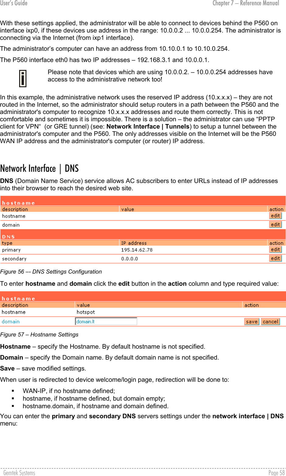
![User’s Guide Chapter 7 – Reference Manual Network Interface | Configuration | Management Subnet Each network interface can have a management subnet. Use the network interface | configuration | management subnet menu to configure this feature on selected interface. When management subnet is enabled, port forwarding will NOT WORK when connecting from IP addresses that are in the management subnet's remote administrator's network. This is because the management subnet allows connecting to the client computer without using port forwarding. The administrator can enable or disable management subnet for each interface. By default no management subnet is enabled on the controller: Figure 54 – Management Subnet To specify new subnet management click the edit button on the selected interface: Figure 55 – Add Management Subnet IP Address and Netmask – specify the IP address and netmask of the management subnet. IP address will be set on the network interface as an alias, so you can connect to the P560 using this address. This IP address should be used on access points as the gateway address. Remote Network and Netmask –specify the remote network that is allowed to access the local management subnet. Only addresses that are from the remote network will be accepted [dots and digits]. If you do not specify any remote network all stations with IP addresses from the management LAN are routed to the WAN port even without being authenticated. Clients using an IP address from the management subnet can browse the Internet without authorization, and no accounting will be done. Thus, it is strongly recommended to allow traffic only from the administrative remote network (no 0.0.0.0/0.0.0.0 in remote specification). Example: Interface configuration for ixp0: type: LAN IP address: 192.168.3.1 netmask: 255.255.255.0 gateway: ixp1 Management subnet on ixp0: IP address: 10.0.0.1 netmask: 255.255.255.0 remote network: 10.10.0.1 remote netmask: 255.255.255.0 Gemtek Systems Page 57](https://usermanual.wiki/GemTek-Technology/AP930621G.User-Manual-Part-1/User-Guide-451086-Page-57.png)
![User’s Guide Chapter 7 – Reference Manual Figure 58 – DNS Redirection Settings The DNS server or DNS address can be obtained dynamically if DHCP, PPPoE and/or PPTP (for DSL) service is enabled. To add DNS server manually click the edit button in the action column and type in the DNS server’s IP address: Figure 59 – Edit DNS Redirection Settings IP address – enter the primary or secondary DNS server’s IP address [in digits and dots notation]. Save – click to save the new DNS server’s settings. Network Interface | DHCP The P560 controller can act as a DHCP server and/or as a DHCP relay gateway. The DHCP (Dynamic Host Configuration Protocol) service is supported on the LAN interfaces [eth0/ixp0/vlan[n]]. This service enables clients on the LAN to request configuration information, such as an IP address, from a server. This service can be viewed in the following table: Figure 60 – DHCP Configuration By default the AC is configured to act as a DHCP server. Each LAN interface runs a different instance of the DHCP service. This service is configured by defining an IP address range and WINS address for client workstations. Other settings, such as the default gateway and DNS server address are configured automatically according to the interface settings. To see the complete DHCP service configuration, click the details button in the action column: Figure 61 – DHCP Settings Details Gemtek Systems Page 59](https://usermanual.wiki/GemTek-Technology/AP930621G.User-Manual-Part-1/User-Guide-451086-Page-59.png)
![User’s Guide Chapter 7 – Reference Manual To edit the DHCP service configuration [DHCP server/DHCP relay], click the edit button in the action column: Figure 62 – Edit DHCP Configuration Settings Status – select status from drop-down menu: Disabled – disable the DHCP service on the selected interface DHCP Server – enabled by default DHCP Relay – to route DHCP through the external server, enable relay service Case 1 Configure the DHCP server Select the interface on which you want to configure the DHCP service [eth0/ixp0/vlan[n]]. Select the DHCP server and click the update button specify the DHCP server parameters: Figure 63 – Edit DHCP Server Settings IP Address from/IP Address to – specify the IP address range supported for the DHCP service [mandatory fields]. WINS Address (Windows Internet Naming Service) – specify service IP address if it is available on the network [dots and digits]. Lease Time – specify the IP address renewal in seconds [1-1000000]. Domain – specify DHCP domain name [optional, 1-128 sting]. DNS address – specify the DNS server’s IP address [in digits and dots notation]. DNS secondary address – specify the secondary DNS server’s IP address [in digits and dots notation]. Case 2 Configure the DHCP relay Select the interface on which you want to configure the DHCP service [eth0/ixp0/vlan[n]]. Select the DHCP relay and click the update button specify the DHCP relay parameters: Gemtek Systems Page 60](https://usermanual.wiki/GemTek-Technology/AP930621G.User-Manual-Part-1/User-Guide-451086-Page-60.png)
![User’s Guide Chapter 7 – Reference Manual Figure 64 – Edit DHCP Relay Settings Circuit ID – the unique DHCP relay parameter [optional, by default the MAC address of the device WAN interface is used]. If DHCP relay service is selected, the default WAN gateway is used automatically. Update – to update entered values, the following screen appears: Figure 65 – Apply or Discard DHCP Server Settings Apply Changes – to save entered new DHCP settings. Discard Changes – to restore previous values. Gemtek Systems Page 61](https://usermanual.wiki/GemTek-Technology/AP930621G.User-Manual-Part-1/User-Guide-451086-Page-61.png)
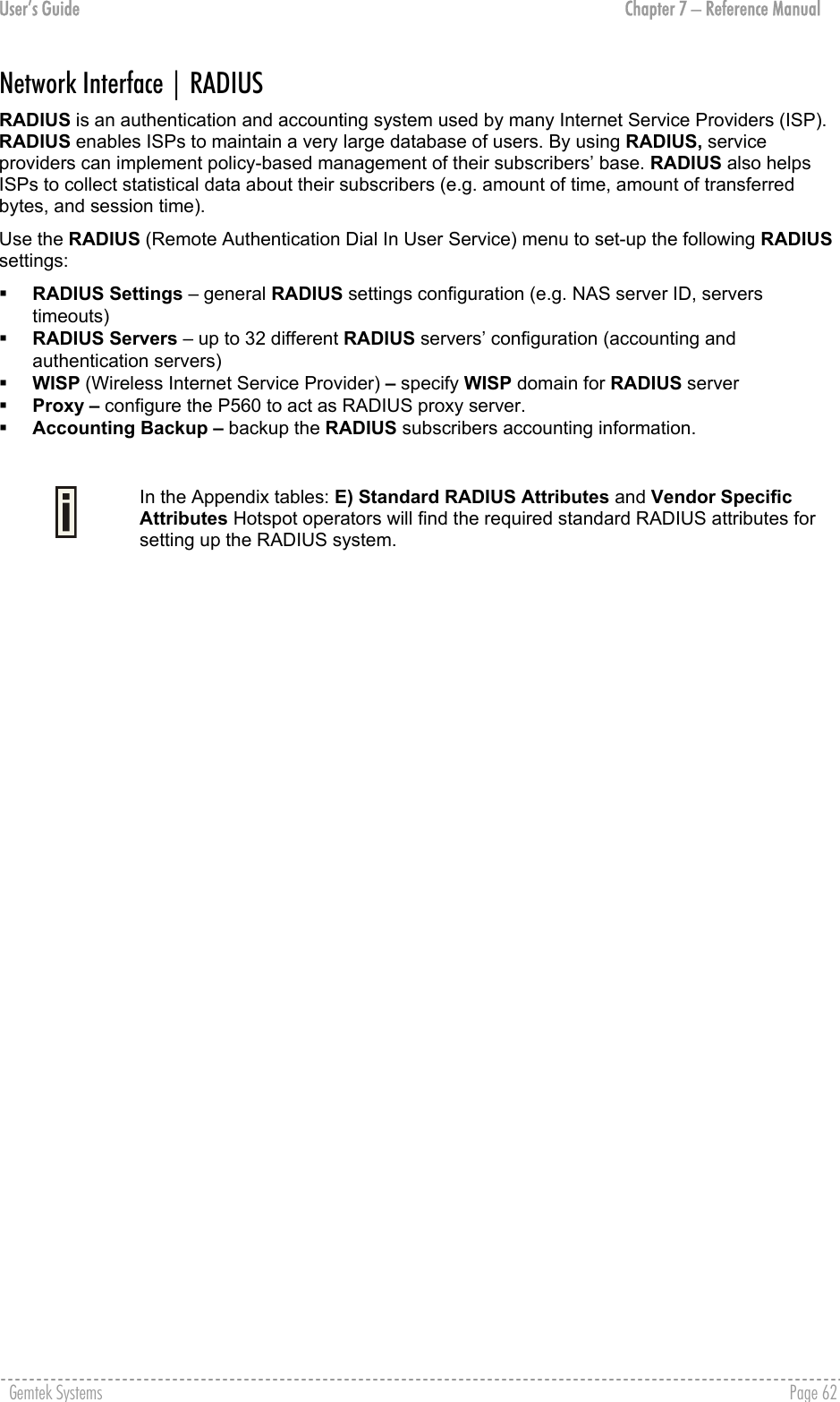
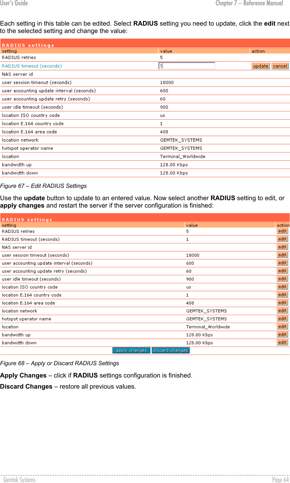
![User’s Guide Chapter 7 – Reference Manual Network Interface | RADIUS | RADIUS Settings General RADIUS settings are configured using the RADIUS settings menu under the network interface: Figure 66 – RADIUS Settings Configuration RADIUS Retries – retry count of sending RADIUS packets before giving up. RADIUS Timeout – maximum amount of time before retrying RADIUS packets [sec]. NAS Server ID – name of the RADIUS client. User Session Timeout - amount of time from the user side (no network carrier) before closing the connection [sec]. User Accounting Update - period after which server should update accounting information [sec]. User Accounting Update Retry – retry time period in which server should try to update accounting information before giving up [sec]. User Idle Timeout - amount of user inactivity time, before automatically disconnecting user from the network [sec]. Location ISO Country code – location ID attribute, country code according ISO standards [string]. Location E.164 Country code – location ID attribute, country code according E.164 specification. Location E.164 Area code – location ID attribute, area code according E.164 specification. See the Location ID and ISO Country codes for your country in the Appendix: F) Location ID and ISO Country Codes. Location Network – location ID attribute, network name [string]. Hotspot Operator Name – location name attribute, operator’s name [string]. Location – location name attribute, textual description of the location [string]. Bandwidth Up – maximum bandwidth up at which corresponding user is allowed to transmit [bps]. Bandwidth Down – maximum bandwidth down at which corresponding user is allowed to receive [bps]. User can check its available bandwidth in the logout page statistics. Gemtek Systems Page 63](https://usermanual.wiki/GemTek-Technology/AP930621G.User-Manual-Part-1/User-Guide-451086-Page-63.png)
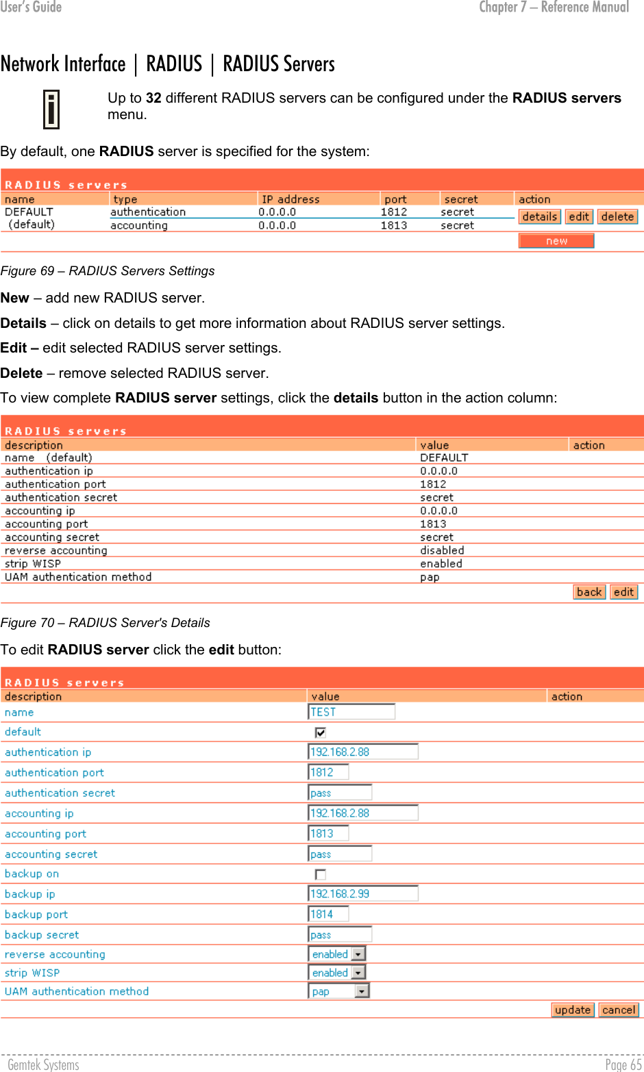
![User’s Guide Chapter 7 – Reference Manual Figure 71 – Add New RADIUS Server Name – specify the new RADIUS server name. Default – check the check box to make the selected RADIUS the default server. Authentication IP – authentication RADIUS server IP address [dots and digits]. Authentication Port – specify the network port used to communicate with RADIUS [1-65535]. The port default value of 1812 is based on RFC 2138 "Remote Authentication Dial-in User Service (RADIUS)". Authentication Secret – shared secret string that is used to encrypt data frames used for authentication server. Accounting IP – accounting RADIUS server IP address [dots and digits]. Accounting Port – specify the network port used to communicate with RADIUS [1-65535]. Accounting Secret – shared secret string that is used to encrypt data frames used for accounting server. Backup IP – backup RADIUS server IP address [dots and digits]. Backup Port – specify the network port used to communicate with RADIUS [1-65535]. Backup Secret – shared secret string that is used to encrypt data frames used for backup server. Shared secret must be the same on RADIUS server and RADIUS client. Reverse Accounting – [enabled/disabled]. The RADIUS accounting request contains Acc-Input-Octets and Acc-Output-Octets attributes. The interpretation of these attributes according the RFC2866 is relative to the point of view. If this point is at the AC - Acct-Input* attributes should contain the bytes/packets received at AC port from the client and Acct-Output* attributes should contain bytes/packets sent from AC port to the client. If we move this point to the client - we will get the reversing of Acct-Input* and Acct-Output* attributes values. The Acct-Input* then should contain bytes/packets received from AC, what is bytes/packets that AC sent to the user in AC point of view and what was Acct-Output*. The AC implementation of RADIUS accounting request is at the client point of view (reverse accounting is disabled). The value "disabled" means that Acct-Input* RADIUS attributes will contain bytes/packets sent to the client and Acct-Output* RADIUS attributes will contain bytes/packets received from the client during the curse of service being provided. The value "enabled" means that info in the Acct-Input* and Acct-Output* RADIUS attributes will be swapped (reversed). That is the Acct-Input* will contain bytes/packets received from the client and the Acct-Output* will contain bytes/packets sent to the client. Strip WISP – [enabled/disabled] select ‘enabled' if you want to strip WISP domain name before sending it to the RADIUS server. Stripping means removing everything before the “/” character including character itself for such user name login format like: “WISPdomain/username”. Select “disabled” if you need to send the user login name to RADIUS server unmodified. Some RADIUS servers can be configured in such way that requires full-unmodified user name to be sent. UAM authentication method – select authentication method from drop-down menu: PAP – Password Authentication Protocol CHAP – Challenge Handshake Authentication Protocol MSCHAP1 – Microsoft Challenge Handshake Authentication Protocol version 1 MSCHAP2 – Microsoft Challenge Handshake Authentication Protocol version 2 Gemtek Systems Page 66](https://usermanual.wiki/GemTek-Technology/AP930621G.User-Manual-Part-1/User-Guide-451086-Page-66.png)
![User’s Guide Chapter 7 – Reference Manual Update – add new specified RADIUS server. Cancel – restore all previous values. After adding a new RADIUS server or editing an existing one, the following controls appears: Apply Changes – save changed configuration. Discard Changes – discard all changes. Restart – after applying changes to the system, you should restart the controller to make applied changes work. Network Interface | RADIUS | WISP Up to 32 WISP entries can be defined using the network interface | RADIUS | WISP menu. Different WISPs (Wireless Internet Service Providers) can be associated with appropriate RADIUS servers and device interfaces using the network interface | RADIUS | WISP menu: Figure 72 – WISP Menu Hotspot subscribers user name format from WISP table is as follows: username@WISPdomain WISPdomain/username New – click to define WISP for RADIUS server. Figure 73 – Define New WISP Name – new WISP domain name [string, up to 256 symbols, no space, dot or dash allowed]. RADIUS Name – select RADIUS for new WISP from list box [non editable]. Bound To – select the WISP binder interface [none/eixp0/ixp1/ixp2/vlan[n]]. The WISP can be associated with appropriate device interface. Update – system with new WISP. Cancel – restore all previous values. Network Interface | RADIUS | Proxy The P560 (AC) can forward the RADIUS authentication and accounting requests from Access Point (AP) to the real RADIUS server. To configure the RADIUS proxy, follow the steps: Step 1 Connect the Access Point to any LAN port available on the Access Controller (P560). The AP should be in the bridge mode. Step 2 Using the network interface | RADIUS | proxy menu configure the RADIUS proxy parameters: RADIUS authentication port (UDP), RADIUS accounting port (UDP) - different from authentication port and Accounting detection timeout: Gemtek Systems Page 67](https://usermanual.wiki/GemTek-Technology/AP930621G.User-Manual-Part-1/User-Guide-451086-Page-67.png)
![User’s Guide Chapter 7 – Reference Manual Figure 74 – RADIUS Proxy Settings RADIUS Proxy Status – select [enabled] to enable the RADIUS proxy feature [enabled/disabled]. Authentication Port – specify the port on AC for listening the RADIUS authentication packets. The AC RADIUS proxy authentication port will accept only RADIUS authentication packets [1-65535, default: 1812]. Accounting Port – specify the port on AC for listening the RADIUS accounting packets. The AC RADIUS proxy accounting port will accept only RADIUS accounting packets [1-65535, default: 1813]. Detection Timeout – specify the RADIUS proxy accounting detection timeout in seconds. The AC will wait the specified period for accounting packet after the authentication request was got [0-3600]. The authentication RADIUS proxy port should differ from the accounting port. Step 3 Configure the AP to send the RADIUS authentication and accounting packets to the AC LAN IP address and UDP ports which are configured on AC RADIUS proxy configuration. Step 4 The RADIUS secrets on AC should be set to value, which is good at the real RADIUS server for which the following packet will be forwarded. Such preconfigured AC will act as RADIUS proxy and will forward the RADIUS authentication and accounting packets from AP according WISP and RADIUS server settings in the AC configuration without any modification. Gemtek Systems Page 68](https://usermanual.wiki/GemTek-Technology/AP930621G.User-Manual-Part-1/User-Guide-451086-Page-68.png)
![User’s Guide Chapter 7 – Reference Manual Network Interface | RADIUS | Accounting Backup The administrator can backup the hotspot subscribers’ RADIUS accounting information in two ways: Via syslog protocol to the specified host Download to the selected location (e.g. on your PC) Use the network interface | RADIUS | accounting backup menu: Figure 75 – Accounting Backup Backup via syslog – enable this type to send the RADIUS accounting information via syslog protocol to the specified host [enable/disable] and note that the Host IP specification is obligatory. Host – enter host IP address where to send accounting backup messages. Backup to local file – enable this option, and the download button appears: Download – click the button to download the accounting information file to your selected location. Both types of accounting backup can be enabled. Gemtek Systems Page 69](https://usermanual.wiki/GemTek-Technology/AP930621G.User-Manual-Part-1/User-Guide-451086-Page-69.png)
![User’s Guide Chapter 7 – Reference Manual Network Interface | Tunnels This chapter describes the configuration of VPN tunnels. VPN tunnels can be used to secure management and AAA traffic between the hotspot network and the network operation center of the operator. The Gemtek Systems Access Controllers support PPTP and GRE tunnels. Furthermore PPP (Point-to-Point Protocol) can be use to authenticate the AC to a authentication server and to assign IP settings to the WAN port of the AC. Network Interface | Tunnels | PPPoE/PPTP/GRE Use the network interface | tunnels | PPPoE/PPTP/GRE menu to connect to ISP via PPTP, PPPoE or GRE tunnel. All traffic will be sent via this tunnel. Default gateway specified in network interface | configuration page will not be used, because all Internet traffic will be sent/received via the specified PPTP, PPPoE or GRE server (tunnel). By default no services are available on the controller: Figure 76 – PPPoE/PPTP/GRE for DSL To specify PPTP tunnel for your controller click the edit button and enter the following: Figure 77 – Specify PPTP Tunnel Service – select service PPTP. Username – enter username to connect to the server [text string, can not be empty]. The same username should be configured on the PPTP server. Password – enter password by which user should be authenticated [text string, can not be empty]. Encryption – enables use of MPPE encryption. Server IP – PPTP server IP address. To specify PPPoE tunnel for your controller click the edit button and enter the following: Figure 78 – Specify PPPoE Tunnel Service – select service PPPoE. Username – enter username to connect to the server [text string, can not be empty]. The same username should be configured on the PPPoE server. Password – enter password by which user should be authenticated [text string, can not be empty]. Gemtek Systems Page 70](https://usermanual.wiki/GemTek-Technology/AP930621G.User-Manual-Part-1/User-Guide-451086-Page-70.png)
![User’s Guide Chapter 7 – Reference Manual Encryption – enables use of MPPE encryption. When PPPoE tunnel is used, then no server IP is required - broadcast address will be used. To specify GRE tunnel for your controller click the edit button and enter the following: Figure 79 – Specify GRE Tunnel Service – select service GRE. Remote IP – IP address of GRE tunnel endpoint [IP address]. Interface IP – enter the IP address of GRE interface [IP address]. Interface Netmask – enter the netmask of GRE interface [netmask]. Network Interface | Tunnels | PPTP Client for VPN PPTP Client for Virtual Private Network (VPN) is designed to secure the management and AAA traffic as well as to establish a VPN tunnel connection to the network operation center, for example when the administrator needs to reach access points behind the P560 from his workstation. Should be used with Management Subnet feature, otherwise the firewall will not be enabled to reach anything behind the P560. Only specific traffic will be sent to the tunnel with everything else sent using the default gateway specified on network interface | configuration page. By default no PPTP clients are defined for the controller: Figure 80 – PPTP Client for VPN To specify new tunnel for your AC, click the new button: Figure 81 – Add PPTP Client Channel Name – enter free form string for tunnel identification (for user only). Server IP Address - IP address [can not be empty]. Username – enter username to connect to the PPTP server [text string, can not be empty]. Password – enter password by which user should be authenticated [text string, can not be empty]. Encryption – enables use of MPPE encryption. Network/Netmask – enter remote network settings [format: dots and digits]. Up to 16 VPN entries can be set. Gemtek Systems Page 71](https://usermanual.wiki/GemTek-Technology/AP930621G.User-Manual-Part-1/User-Guide-451086-Page-71.png)
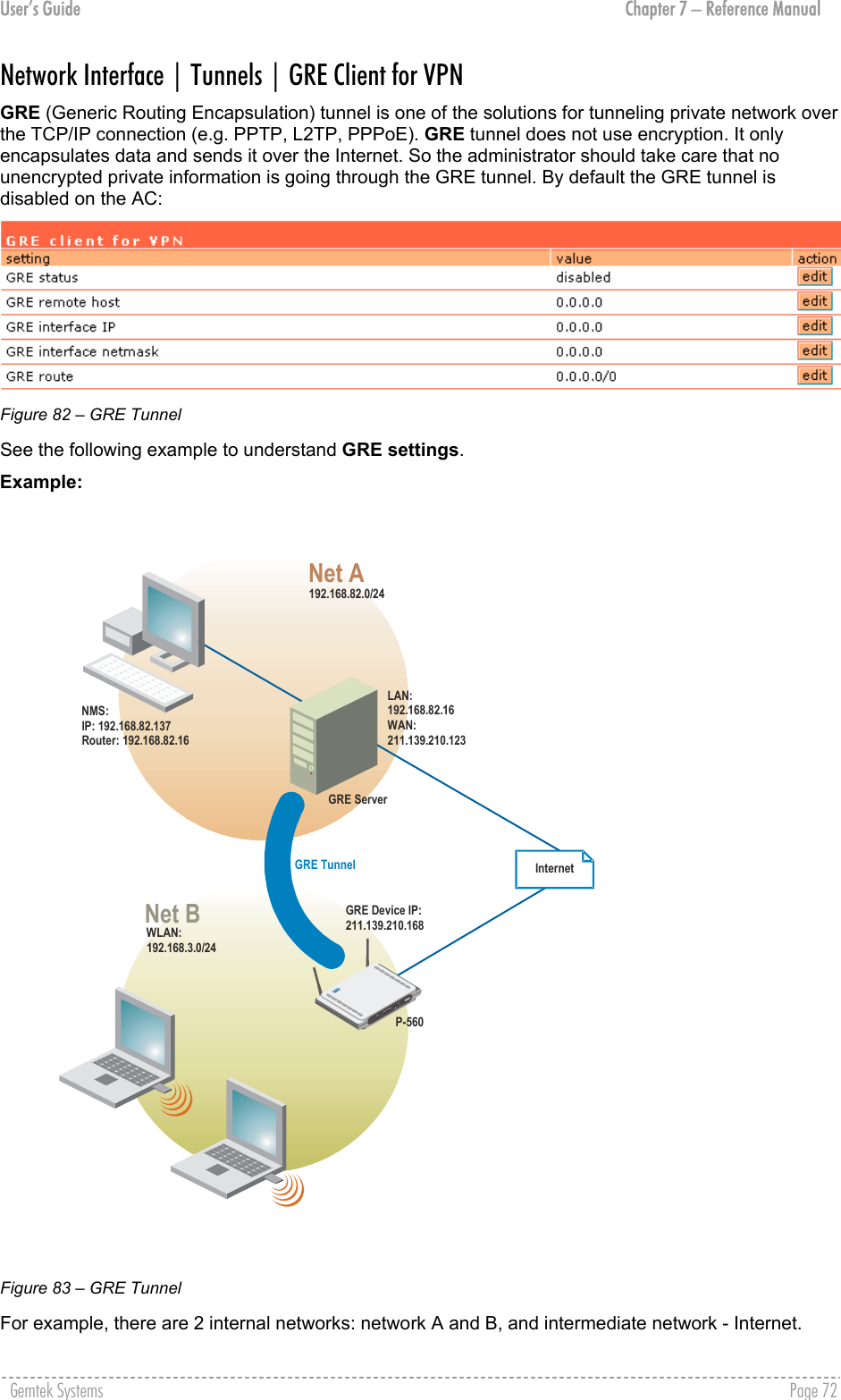
![User’s Guide Chapter 7 – Reference Manual Network A (administrator's computer with Network Management System); we shall call this network (192.168.82.0/24) “Net A”. Network: 192.168.82.0 Netmask: 255.255.255.0 Router: 192.168.82.16 GRE server has two interfaces, LAN and WAN: LAN IP: 192.168.82.16 WAN IP: 211.139.210.123 Settings in GRE tunnel page: GRE Remote Host: 211.139.210.123 GRE Route: 192.168.82.0/24 Network B has subscribers on wireless P-560 interface (eth0) we shall call this network (192.168.3.0/24) “Net B”: Network: 192.168.3.0 Netmask: 255.255.255.0 Router: 192.168.3.1 Where GRE interface (WAN IP of AC) is 211.139.210.168. Settings in GRE tunnel page: GRE Device IP: 211.139.210.168 GRE Device Netmask: 255.255.255.0 Settings in Management Subnet page on eth0 interface (network interface | configuration | management subnet menu) of AC: IP Address: 192.168.3.1 Netmask: 255.255.255.0 Remote Network: 192.168.82.1 Remote Netmask: 255.255.255.0 Figure 84 – Management Subnet Settings As far as the Internet is concerned, we assume that it will pass any packet sent from A to B and vice versa. With settings from above, the administrator from Net A will be able to access clients on Net B through the GRE tunnel between the GRE server and the GRE interface of AC. Use the edit button next to a setting to change its value: Figure 85 – GRE Settings GRE Status – select one: [enabled or disabled]. Remote Host – IP address of GRE tunnel endpoint [IP address]. GRE Interface IP – enter the IP address of GRE interface [IP address]. Gemtek Systems Page 73](https://usermanual.wiki/GemTek-Technology/AP930621G.User-Manual-Part-1/User-Guide-451086-Page-73.png)
![User’s Guide Chapter 7 – Reference Manual GRE Interface Netmask – enter the netmask of GRE interface [dots and digits]. GRE interface IP/Netmask settings is important when configuring the GRE server. GRE Route – this is the destination network for the GRE tunnel in the combined node/subnet format [IP address/N]. The /N stands for the number of bits that are in the network address. There are 32 bits, so we have 32-N bits left that are part of our network. The first N bits of x.x.x.x correspond to x.0.0.0 when N=8, our network address, and the netmask is 255.0.0.0 (when N=8). bits netmask /32 255.255.255.255 /31 255.255.255.252 /30 255.255.255.248 … … /26 255.255.255.192 /25 255.255.255.128 /24 255.255.255.0 … … /16 255.255.0.0 … … /8 255.0.0.0 … … /0 0.0.0.0 Gemtek Systems Page 74](https://usermanual.wiki/GemTek-Technology/AP930621G.User-Manual-Part-1/User-Guide-451086-Page-74.png)
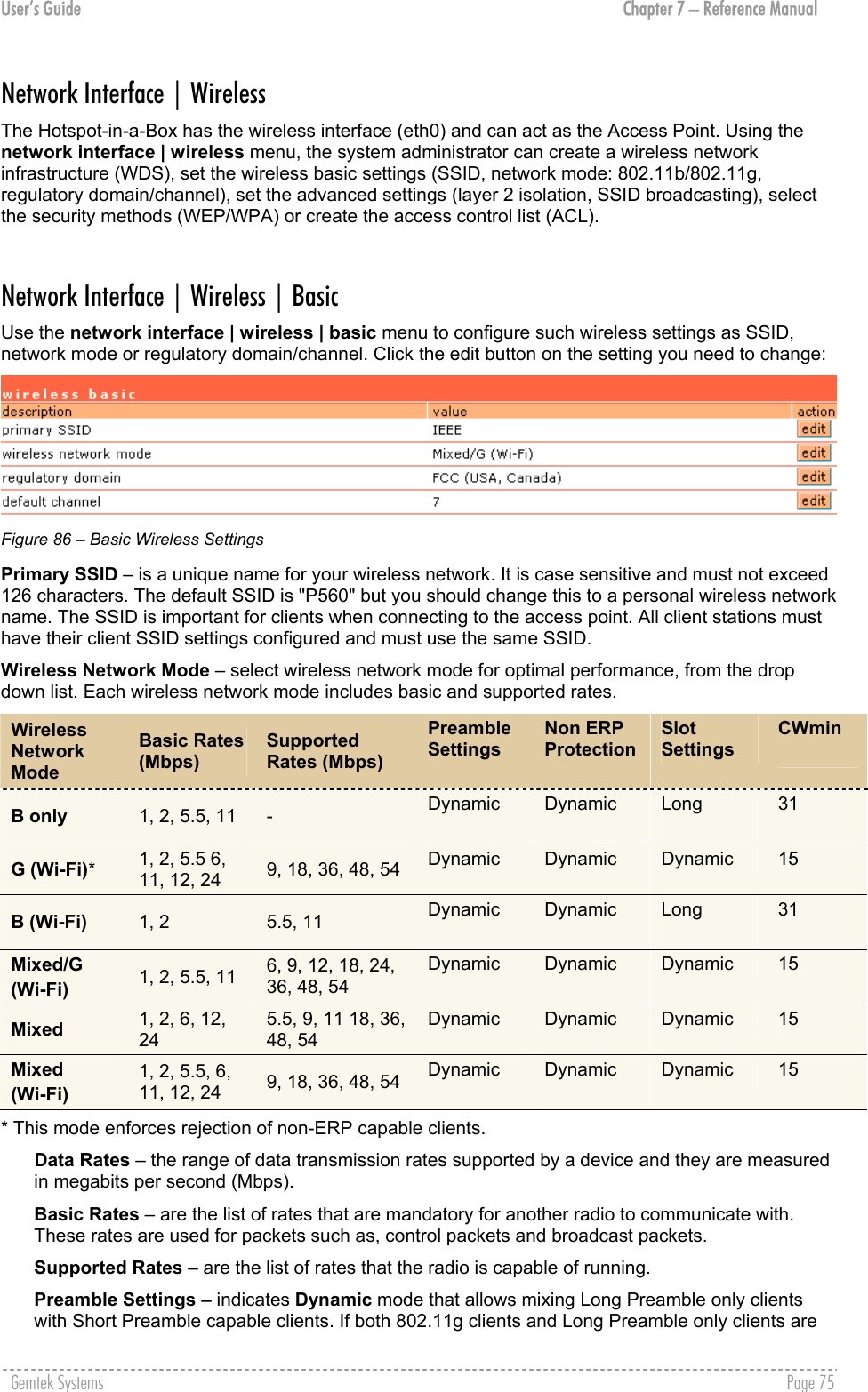
![User’s Guide Chapter 7 – Reference Manual Network Interface | Wireless | Advanced Use the network interface | wireless | advanced menu to configure the layer 2 client isolation, SSID broadcasting or threshold values or wireless card output power: Figure 87 – Advanced Wireless Setting Layer 2 Isolation – Layer 2 wireless client separation. Connected clients with user isolation function enabled cannot access each other directly. The clients are isolated from each other using their MAC addresses [enabled/disabled]. SSID Broadcasting – when enabled, your AP’s SSID is visible in the networks list while scanning the available networks for wireless client. When disabled, the AP’s SSID is not visible in the available network list (SSID is not broadcasted with its Beacons) [enabled/disabled]. By default the SSID broadcasting is enabled. Fragmentation Threshold –the fragmentation threshold, specified in bytes, determines whether packets will be fragmented and at what size. On an 802.11 wireless LAN, packets exceeding the fragmentation threshold are fragmented, i.e., split into, smaller units suitable for the circuit size. Packets smaller than the specified fragmentation threshold value are not fragmented [[256-2346] default: 2346 (2346 means that fragmentation is disabled)]. RTS Threshold – when set, this setting specifies the maximum packet size beyond which the Wireless LAN Card invokes its RTS/CTS mechanism. Packets that exceed the specified RTS threshold trigger the RTS/CTS mechanism. The NIC transmits packets smaller than this threshold without using RTS/CTS [[0-2347] default: 2347 (2347 means that RTS is disabled)]. Output Power – the wireless card transmission output power in dBm [0-31]. Antenna Gain (dBi)– is the gain of the connected antenna in relation to an isotropic radiated power. Total output power (wireless output power plus antenna gain) should comply with local radio regulations. Refer to the Appendix: C) Regulatory Domain/Channels. Network Interface | Wireless | Security Secure your wireless network use one of the available encryption methods: WEP (Wired Equivalent Privacy) with 64-bit/128-bit encryption WPA (Wi-Fi Protected Access) with pre shared key or with RADIUS server The WPA is a far stronger protocol and fixes the weaknesses in WEP. To enable the WPA security for your WLAN you will need: An access point that has WPA support (e.g. Gemtek Systems P-560) A wireless network card that has WPA drivers available A mobile client that supports WPA and your operating system To configure the WPA with pre-shared key security on the P-560 use the network interface | wireless | security menu, select the WPA with pre-shared key security method and enter the pre-shared key: Gemtek Systems Page 77](https://usermanual.wiki/GemTek-Technology/AP930621G.User-Manual-Part-1/User-Guide-451086-Page-77.png)
![User’s Guide Chapter 7 – Reference Manual Figure 88 – WPA with Pre-shared Key Security Settings Pre-shared Key – specify the pre-shared key for WPA security [8-64 characters]. The encryption pre-shared key must also be entered into the WLAN card configuration of the mobile clients. Update – click the button to apply security setting to your wireless network. WPA with RADIUS server makes use of external AAA (RADIUS) server to generate and exchange dynamic WPA keys between P-560 and user station. To configure the WPA with RADIUS server security on the P-560 use the network interface | wireless | security menu and select the WPA with RADIUS server security method: Figure 89 – WPA with RADIUS Server Security Settings To configure the WEP encryption, select the WEP key algorithm and enter the pre-shared key: Figure 90 – WEP Security Settings WEP keys are entered as a series of colon-separated HEX (0-9, A-F, and a-f) pairs: 5 pairs for 64-bit (e.g. 00:AC:01:35:FF) 13 pairs for 128-bit (e.g. 00:11:22:33:44:55:66:77:88:99:AA:BB:CC) The encryption pre-shared key must also be entered into the WLAN card configuration of the mobile clients. Network Interface | Wireless | ACL Use the ACL service to control the default access to the wireless interface (eth0) of the AC or define special access rules for mobile clients. Configure the ACL using the network interface | wireless | ACL menu: Gemtek Systems Page 78](https://usermanual.wiki/GemTek-Technology/AP930621G.User-Manual-Part-1/User-Guide-451086-Page-78.png)
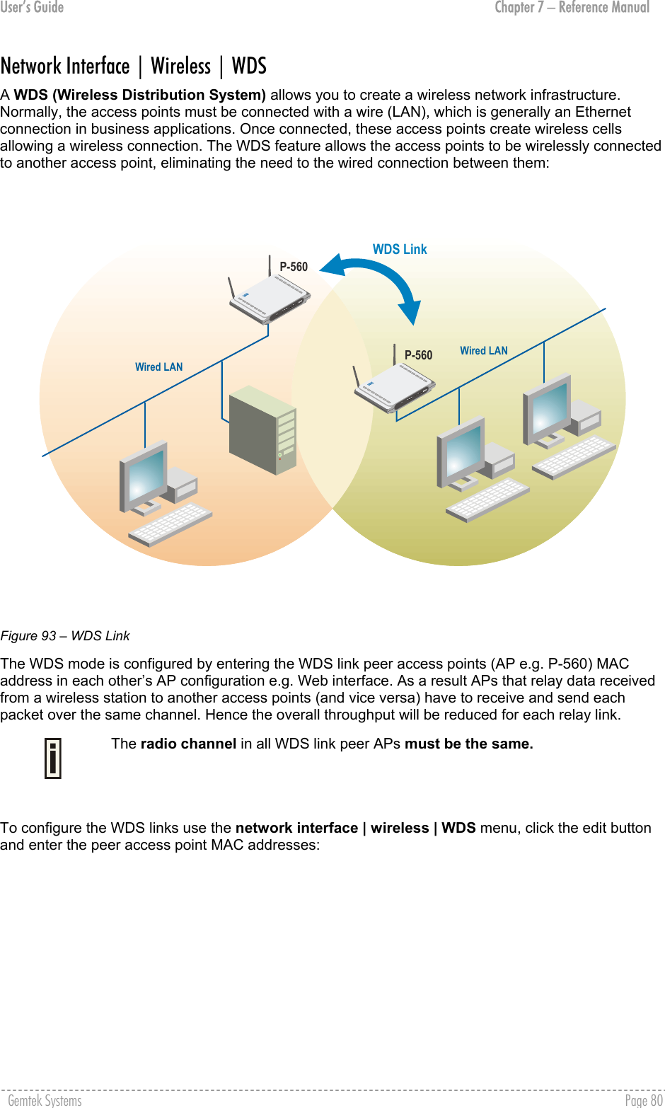
![User’s Guide Chapter 7 – Reference Manual Figure 91 – ACL Service ACL service – click the edit button to enable or disable the access control service on device. By default the ACL service is disabled and all mobile clients connections to the AC are allowed (no ACL rules are applied to the mobile clients). Default ACL policy – click the edit button to change the default ACL policy [allow/deny]. Select allow to allow all mobile clients to access this access point or deny to prevent all mobile clients from accessing your access point. Clients may also be subject to rules in the MAC addresses and policies table. You can create your own access list if you need to define special access rules for specific network devices. The access control list is based on the network device's MAC address. In the MAC addresses and policies table, you need only specify the network device MAC address and its access policy (accept/deny) with the new rule. Click the new button to define the ACL rule: Figure 92 – Add ACL Rule MAC Address – enter the physical address of the network device you need to (MAC address) The format is a list of colon separated hexadecimal numbers (for example: 00:AA:A2:5C:89:56). Policy – select the permission of the rule to determine whether the specified network device should be allowed or denied as an access point client [allow/deny]. The special ACL rule policy should differ from the default ACL policy otherwise the ACL rule does not work. Update – click the button to add new ACL rule. Gemtek Systems Page 79](https://usermanual.wiki/GemTek-Technology/AP930621G.User-Manual-Part-1/User-Guide-451086-Page-79.png)
![User’s Guide Chapter 7 – Reference Manual Figure 94 – Add WDS Link MAC for Per AP [1-8] – enter wireless interface (eth0) MAC address of the peer AP for the WDS link [6-HEX pairs separated by colon [1-9] [A-F] [a-f]]. You can discover the wireless interface (eth0) MAC address of your P-560 in the system | status page. Update – click the button to update you system with WDS links. Gemtek Systems Page 81](https://usermanual.wiki/GemTek-Technology/AP930621G.User-Manual-Part-1/User-Guide-451086-Page-81.png)
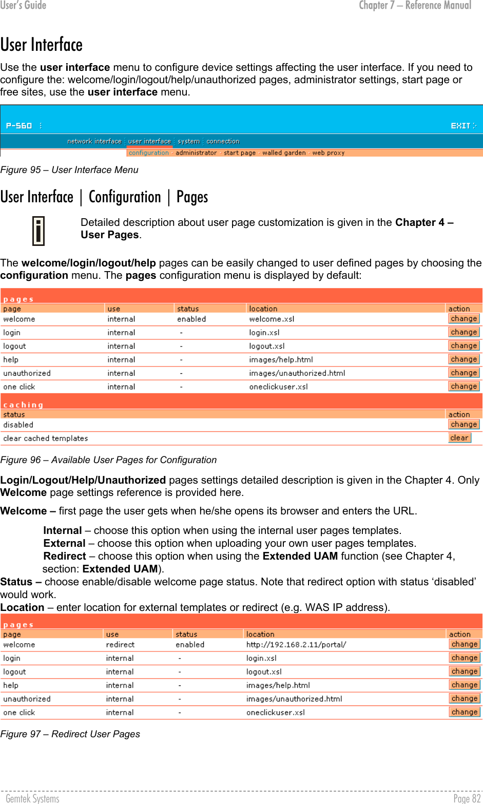
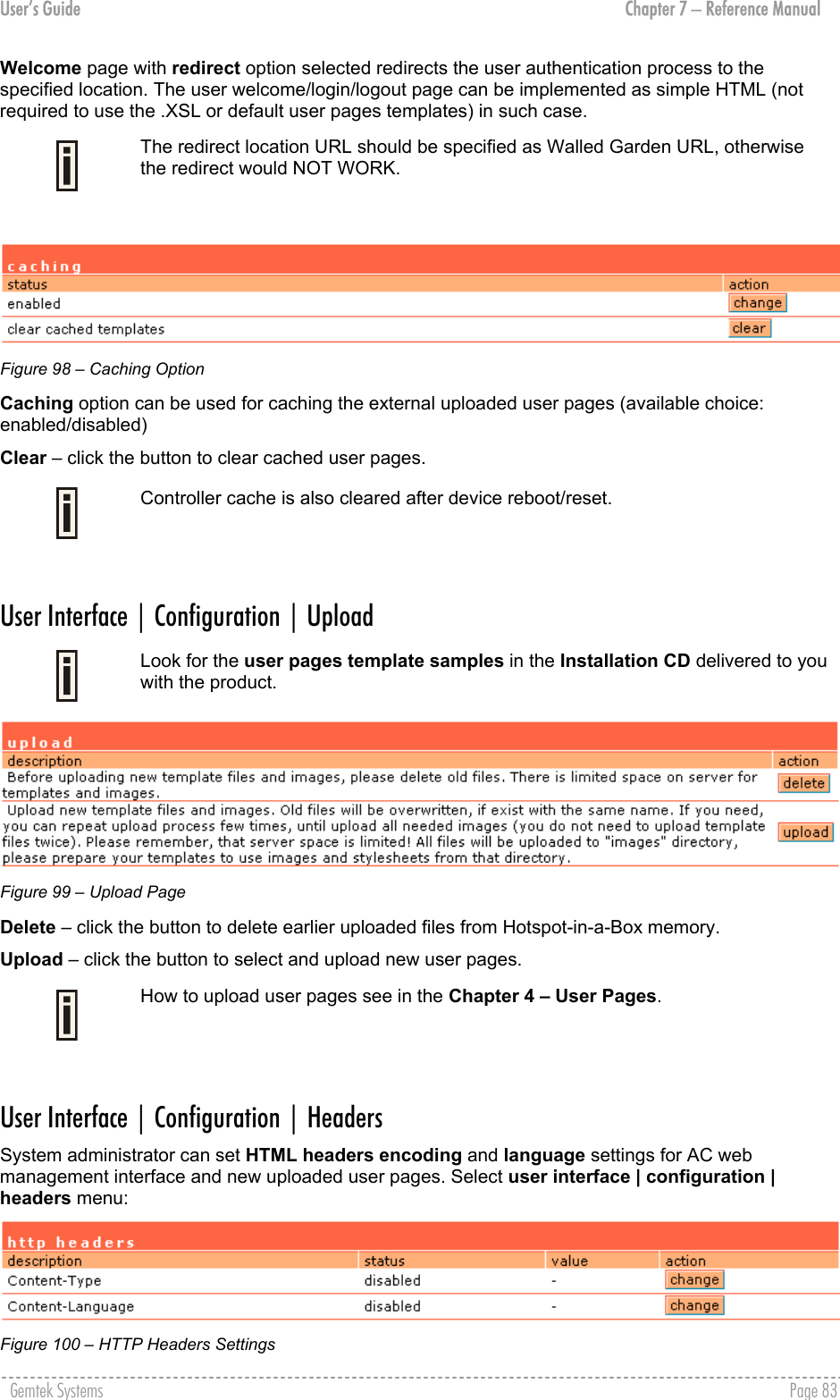
![User’s Guide Chapter 7 – Reference Manual P560 device supports some http META tags. Syntax of such META tags: <META HTTP-EQUIV="name" CONTENT="content"> Currently P560 supports Content-Type and Content-Language tags: Content-Type is used to define document char set (used, when text has non-Latin letters, like language letters). Content-Language may be used to declare the natural language of the document. P560 automatically adds defined content-type and content-language to generated XML. Then user pages (.XSL) templates will use these parameters to generate the output HTML. Click the change button to define new headers of the web management interface on user pages templates. The default HTML encoding is ISO-8859-1, language = English. Enable the HTTP header status and default values appear: Figure 101 – Set HTTP Headers The system administrator can set his own header encoding and language settings. Use the HTML 4.01 specification to define the header encoding and language. User Interface | Configuration | Remote Authentication Read more about extensions feature in Chapter 4, section: Extended UAM. The Remote Authentication feature under the user interface | configuration menu allows an external Web Application Server (WAS) to intercept/take part in the user authentication process, externally log on and log off the user as necessary. It provides means to query user session information as well. By default such remote authentication is disabled: Figure 102 – Remote Authentication Click the edit button next to appropriate settings to specify remote authentication parameters: Figure 103 – Enable Remote Authentication Remote Authentication – select status: [enabled/disabled]. Shared Secret – enter password for WAS to communicate with AC [sting (4-32), no spaces allowed]. Gemtek Systems Page 84](https://usermanual.wiki/GemTek-Technology/AP930621G.User-Manual-Part-1/User-Guide-451086-Page-84.png)
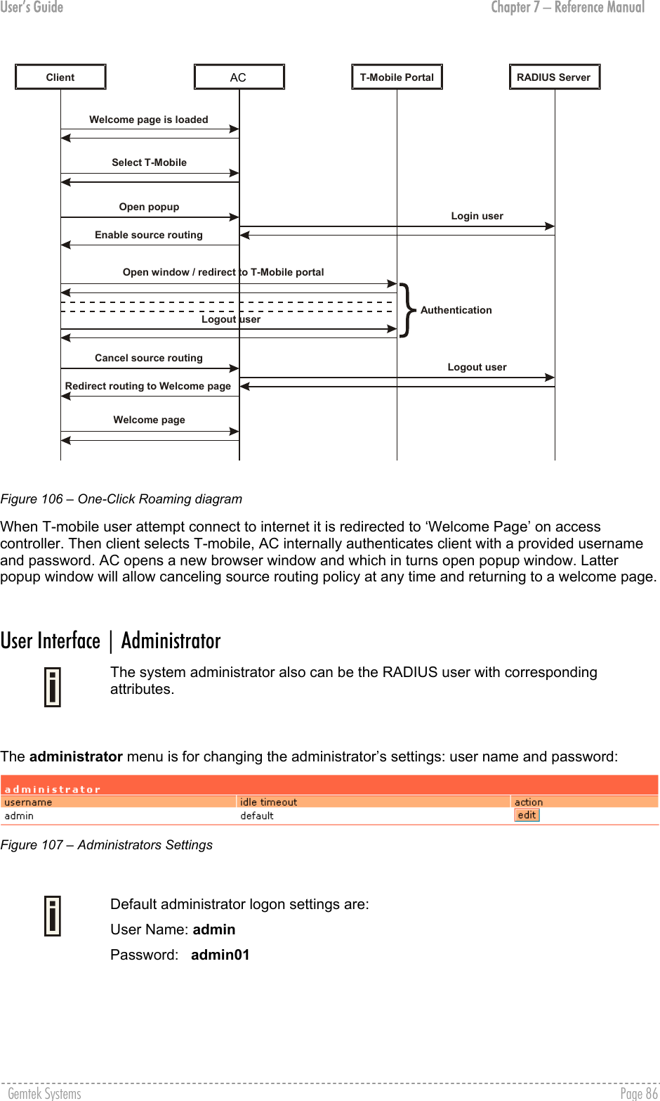
![User’s Guide Chapter 7 – Reference Manual User Interface | Configuration | One-Click Roaming One-Click roaming is the ability of T-mobile customers to use the T-mobile Hotspot service in Third Part Hotspots, while the authentication and billing is entirely realized through T-mobile. The Third Part Hotspot only provides the access to the T-mobile WLAN platform. Use the network interface | configuration | one click menu to configure this feature. By default One-Click roaming is disabled. Click the edit button to change roaming status. Figure 104 – One-click Roaming Settings To add a new One-Click partner, click the new button: Figure 105 – Add new One-Click partner Name – enter One-Click roaming partner’s name. Status – select status: [enabled/disabled]. Username – enter username that is valid user name on RADIUS server [text string, can not be empty]. Password – enter password by which user should be authenticated [text string, can not be empty]. Portal URL – enter T-mobile portal URL to redirect user when One-Click roaming is enabled (optional parameter). Type – choose source routing policy: clients’ traffic can be either routed directly via secondary router or via PPTP tunnel. Choose gateway to route clients’ traffic via specified router’s IP address. Or choose PPTP- [name] tunnel that was created for t-mobile users’ traffic to route through. IP address – enter One-Click roaming gateway IP address that is reachable via WAN interface [can not be empty if gateway type is selected]. Update – click to update One-Click roaming settings. Welcome Pages are stored on Portal. Every user, even T-mobile and Netcheckin will see Welcome pages loaded from Portal server. The Welcome page with portal URL should be entered on network interface | configuration | page. See the following diagram to understand One-Click roaming: Gemtek Systems Page 85](https://usermanual.wiki/GemTek-Technology/AP930621G.User-Manual-Part-1/User-Guide-451086-Page-85.png)
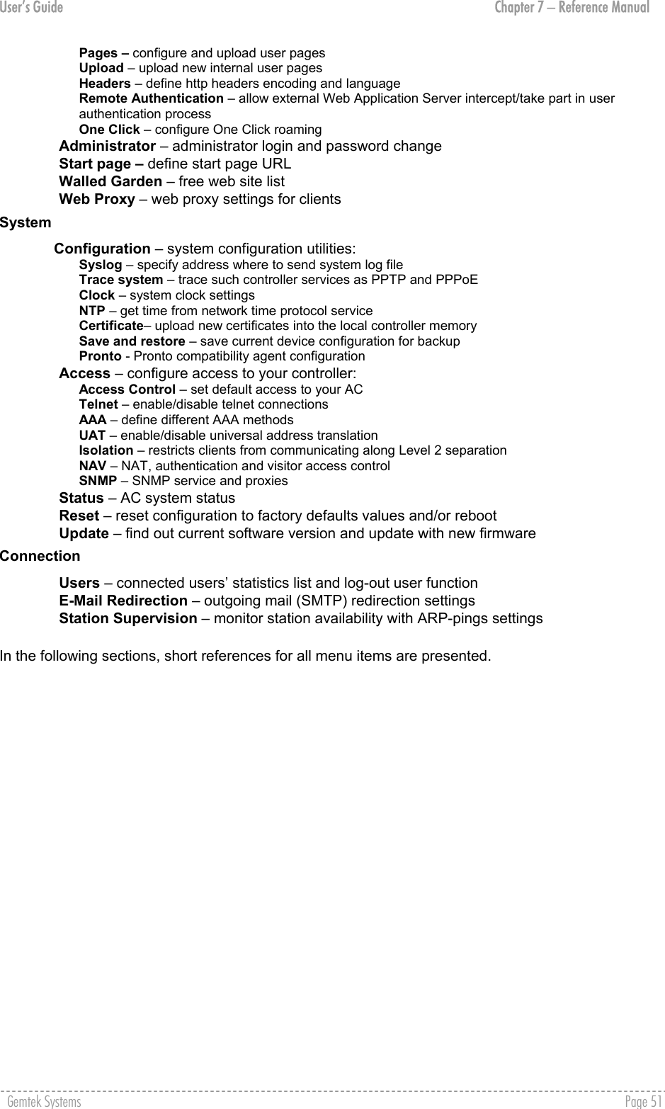
![User’s Guide Chapter 7 – Reference Manual To edit or change the administrator settings simply click the edit button: Figure 108 – Change Administrator Settings Username – administrator username for access to Access Controller (e.g. web interface, CLI mode) [1-32 symbols, spaces not allowed]. Idle Timeout – amount of administrator inactivity time, before automatically disconnecting administrator from the web interface [300-3600 seconds]. The default idle time: 10minutes (600 seconds). Old Password – old password value. New Password –new password value used for user authentication in the system [4-32 symbols, spaces not allowed]. Confirm Password – re-enter the new password to verify its accuracy. Save – click to save new administrator settings. User Interface | Start Page The start page is the default web page where users will be redirected after log-on. This value will be overwritten by the WISP RADIUS attribute no.4 "Redirection-URL" if provided in the authentication response message. Use the user interface | start page menu to view or change the start page URL: Figure 109 – Start Page The administrator can change the start page by clicking the edit button. The value entry field will change into an editable field: Figure 110 – Edit Start Page Value – enter new redirection URL of start page in valid format [http://www.startpageurl.com]. Save – to save new settings. Cancel – restores all previous values. User Interface | Walled Garden The walled garden is an environment that controls the user's access to Web content and services. This feature gives the ability to define a free, restricted service set for a user not yet logged into the system. Use the user interface | walled garden menu to view or change the free URLs or hosts: Gemtek Systems Page 87](https://usermanual.wiki/GemTek-Technology/AP930621G.User-Manual-Part-1/User-Guide-451086-Page-87.png)
![User’s Guide Chapter 7 – Reference Manual Figure 111 – Walled Garden Edit – edit the selected URL or host. All settings become available for editing. New URL – click the new URL button and enter the new URL and its description. Save entered information by clicking the update button: URL for User – define full URL address [www.gemtek-systems.com]. String to Display – site description visible to user as link on the welcome and login page: Figure 113 – Walled Garden link in the Welcome Page New Host – If you need to define hosts (web servers) for walled garden, specify hosts by clicking the new host button and click the update button: Figure 114 – Walled Garden Host Type –select the data traffic protocol for host server [TCP/UDP]. Netmask – enter the network mask to specify the host servers network. Port – network port, which is used to reach the host [1-65535]. For standard protocols use the default ports: Port Delete – delete the selected URL or host. Figure 112 – Add New URL part 1 Host – Web server address [IP address or host name]. Protocol HTTP 80 HTTPS 443 FTP 21 Gemtek Systems Page 88](https://usermanual.wiki/GemTek-Technology/AP930621G.User-Manual-Part-1/User-Guide-451086-Page-88.png)
![User’s Guide Chapter 7 – Reference Manual User Interface | Web Proxy The enabled web proxy allows any clients’ connections with configured proxy settings on their browsers. The AC accepts any client proxy configurations and grants the access to the Internet. The system administrator should list only ports the AC is listening on for proxy requests. Figure 115 – Web Proxy Web proxy is enabled by default and the port numbers are: 3128 and 8080. To add more port number for web proxy, click the new button: Figure 116 – Add Web Proxy Port Port – add port number for web proxy to listen to [1-65535]. Save – click the button to save new proxy port number. Gemtek Systems Page 89](https://usermanual.wiki/GemTek-Technology/AP930621G.User-Manual-Part-1/User-Guide-451086-Page-89.png)
![User’s Guide Chapter 7 – Reference Manual System Use the system menu to configure such system utilities: Syslog – for sending system and debug messages via the syslog protocol. Trace system – trace such controller services as PPTP and PPPoE. Clock – manual setting of internal device clock. NTP – set the Network Time Protocol service on the AC. Certificates – upload your own SSL certificate and private key files for server. Save and Restore – save current AC configuration and restore. Use the system menu to define default access/visitor access to the device via or using: Telnet – enable telnet connections to AC. AAA – enable different AAA methods. UAT – enable the service. SNMP – enable/configure SNMP management. Use the system menu to check the system status, reset the device, or update with new firmware. Figure 117 – System Menu System | Configuration | Syslog You can trace your AC system processes and get the system log messages remotely using the system | configuration | syslog menu (by default the syslog utility is disabled): Figure 118 – Syslog Settings To enable the syslog remote sending function, click the edit button and choose the enabled option: Figure 119 – Configure Syslog Messages Remote Log Status – choose disable/enable remote log [enabled/disabled]. Host – specify the host IP address where to send the syslog messages [host IP address]. Be sure the remote host is configured properly to receive the syslog protocol messages. Level – select the messages level you need to trace. The level determines the importance of the message. The levels are, in order of increasing importance: Debug – debug messages including more important level messages: [info/warning/error/fatal]. Informational – informational messages including [warning/error/fatal] Warning – warning condition messages including [error/fatal] Error – error and critical condition messages including [fatal] Fatal – critical and fatal condition for device messages. Actions should be taken immediately. Gemtek Systems Page 90](https://usermanual.wiki/GemTek-Technology/AP930621G.User-Manual-Part-1/User-Guide-451086-Page-90.png)
![User’s Guide Chapter 7 – Reference Manual Save – save changes. The syslog messages will be started to send to the specified host. Cancel – restore the previous values. System | Configuration | Trace System The trace system utility debugs system services and protocols if malfunction occur. Trace system works with started services as DHCP, PPTP, PPPoE, telnet and SNMP and shows number of system messages according to the selected history size. The trace system can help operators to locate mis-configurations and system errors. Select system | configuration | trace system menu to view current syslog messages in case of troubleshooting of one of the services: Figure 120 – Trace System By default, trace system utility is switched on. The latest messages are displayed at the end of the message list. History Size – select the message history size to display [102400-512000 bytes]. Level – select the messages level you need to trace. The level determines the importance of the message. The levels are, in order of increasing importance: Debug – debug messages including more important level messages: [info/warning/error/fatal]. Informational – informational messages including [warning/error/fatal] Warning – warning condition messages including [error/fatal] Error – error and critical condition messages including [fatal] Fatal – critical and fatal condition for device messages. Actions should be taken immediately. Change – click the change button to apply new history size or selected message level. Trace system will start to sort by selected level at once you click the change button. Clear – delete all displayed messages. Refresh – click to refresh trace system messages. System | Configuration | Clock To set the Hotspot-in-a-Box internal clock, use the clock utility, accessed by selecting the system | configuration | clock menu link: Figure 121 – Clock Utility Gemtek Systems Page 91](https://usermanual.wiki/GemTek-Technology/AP930621G.User-Manual-Part-1/User-Guide-451086-Page-91.png)
![User’s Guide Chapter 7 – Reference Manual To adjust the clock settings, click the change button: Figure 122 – Set Clock Settings Date – specify new date value [year/month/day]. Time – specify time [hours: minutes]. Time Zone – select the time zone [-12.00 – 14.00]. If the NTP service is enabled the selected time zone will be applied to the clock settings also. If the NTP server (see the next section for reference) is enabled on the system, no manual clock setting is available except time zone. Figure 123 – Clock and NTP Only time zone change is available when NTP server is used. System | Configuration | NTP The NTP (Network Time Protocol) is used to synchronize the clock of the AC to a selected time reference. You can synchronize the system clock settings using the system | configuration | NTP menu: Figure 124 – NTP Service By default NTP service is disabled. To start the service, click the edit button: Figure 125 – Enable NTP Status – select appropriate status for NTP service [enabled/disabled]. Host – specify the trusted NTP server IP on the field. It works only with enabled NTP function. The NTP synchronize the device clock with GMT + 0 time. If you need to set the time zone, use the system | configuration | clock menu. You may want to add more than one NTP host, for example, in the case where the first host fails to connect. Click the new button to add additional host settings: Gemtek Systems Page 92](https://usermanual.wiki/GemTek-Technology/AP930621G.User-Manual-Part-1/User-Guide-451086-Page-92.png)
![User’s Guide Chapter 7 – Reference Manual Figure 126 – Add New NTP Host Host – add additional NTP service hosts [1-128]. This NTP server will be used, if connection to the first defined NTP server is lost. System | Configuration | Certificate You can upload your own SSL certificates files for HTTP connection using the certificate menu under the system | configuration menu: Figure 127 – Certificate Upload Only these certificate files are accepted: Server PEM-encoded X.509 certificate file Server PEM-encoded private key file Click the upload to upload your own SSL certificates and private key files: Figure 128 – Upload New Certificate Certificate File – the PEM-encoded certificate file for the server. Corresponding RSA or DSA private keys SHOULD NOT be included. Private Key File – the PEM-encoded private key file for the server. Private key SHOULD NOT be encrypted with a password. This private key should correspond to the certificate above. Upload – upload new certificates. Depending on the public key infrastructure implementation, the certificate includes the owner's public key, the expiration date of the certificate, the owner's name, and other information about the public key owner. The default certificate implemented in the AC includes the following: Gemtek Systems Page 93](https://usermanual.wiki/GemTek-Technology/AP930621G.User-Manual-Part-1/User-Guide-451086-Page-93.png)
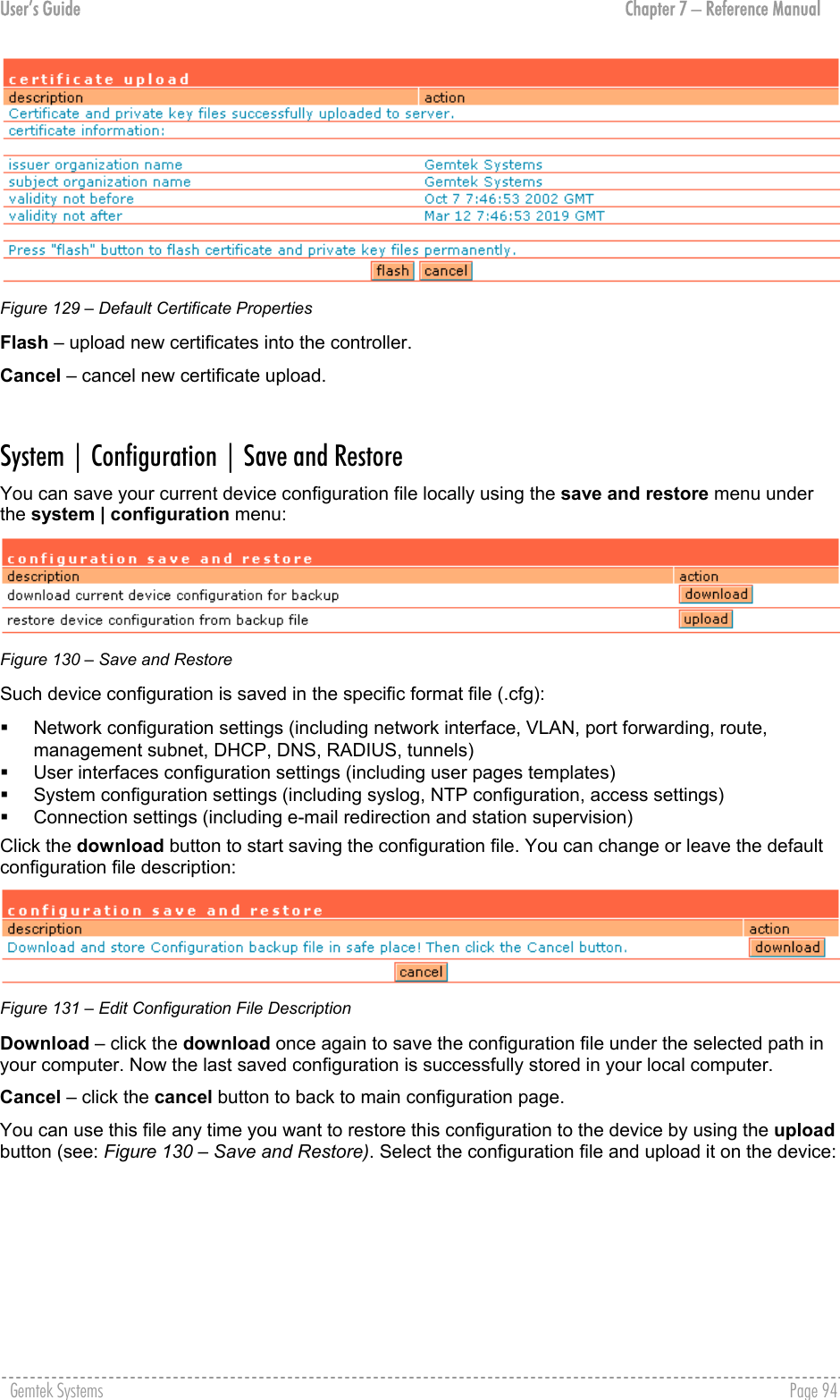
![User’s Guide Chapter 7 – Reference Manual Figure 132 – Upload Configuration File Flash – click the button to apply configuration setting to the device. System | Configuration | Pronto The goal of the pronto-compatible agent program is to ensure that a partner’s hotspot is interoperable with Pronto’s Hotspot OSS. Pronto compatibility agent is used to download and overwrite current configuration (only some parameters which are listed below) from pronto server using WEB proxy. On device boot only these parameters will be overwritten: LAN IP. WLAN (wireless LAN) IP. LAN DHCP range, DHCP default lease time, max lease time. WLAN DHCP range, DHCP default lease time, max lease time. WLAN channel. WLAN SSID. WEP key length (64-bit or 128-bit). WEP key format (HEX). SMTP server IP and port. Location name. Walled garden entries. Default RADIUS authentication, accounting and accounting backup servers IP. Default RADIUS authentication, accounting and accounting backup shared secrets. SNMP Read-Only and Read-Write communities. SNMP traps host. There will be created 3 traps with different trap types (v1, v2, inform) on the same host. By default Pronto feature is disabled: Figure 133 – Default Pronto Settings Gold pronto status – select pronto compatibility agent status [enable/disable]. HNS server URL – specify HNS server URL. Heartbeat interval – specify interval between heartbeat messages in seconds: 1-4 numbers [0-3600], no spaces allowed. ‘0’ means that heartbeat is disabled. No heartbeat value specified - system will use external server value. Heartbeat messages are sending between the nodes that indicate a node is up and running. Remote host – specify remote host [IP address or host name]. Remote port – specify remote host port number: 1-5 numbers, no spaces allowed, [1-65535]. Gemtek Systems Page 95](https://usermanual.wiki/GemTek-Technology/AP930621G.User-Manual-Part-1/User-Guide-451086-Page-95.png)
![User’s Guide Chapter 7 – Reference Manual Edit – click to edit required parameter. Change Pronto status to enable and configure the rest Pronto settings. To configure Pronto settings, click the edit button next to appropriate parameter and specify value. Reboot the device. Figure 134 – Configure Pronto Settings Update – click the button to apply pronto agent settings. Cancel – restore the previous value. After reboot device’s configuration will be changed automatically. Note that if Pronto agent is enabled, after reboot existing configuration will be overwritten with Pronto server parameters’ values. System | Access | Access Control Use the access control menu to control the access management to your AC and to specific services. Access control to your device includes access to these services: Telnet SSH SNMP Thus, the administrator can control the access of a single or every user to the controller via telnet, SSH or SNMP. This can be done by creating the access control list in the AC and checking the incoming user’s IP address. Default access status is used to deny all connections except the SNMP service to the controller. SNMP service is used to access your device via the KickStart utility. Figure 135 – Access Control Edit – click to edit the default access status [allow/deny]. New – click to create new access control rule for specific network to specific service(s) [all/ /ssh/telnet/snmp]. To configure the access control, click the edit button and specify the network address and select services to allow/deny: Figure 136 –Modify Access Control Gemtek Systems Page 96](https://usermanual.wiki/GemTek-Technology/AP930621G.User-Manual-Part-1/User-Guide-451086-Page-96.png)
![User’s Guide Chapter 7 – Reference Manual Service – select services that access you need to control [all/ssh/telnet/snmp]. Telnet service should be also enabled in the system | access | telnet to allow the telnet access to the controller. Otherwise, the client or network will not get telnet access. Network Address – specify the network or host address with netmask in bit format separated by dash. The /N stands for the number of bits that are in the network address. There are 32 bits, so we have 32-N bits left that are part of the network. The first N bits of x.x.x.x correspond to x.0.0.0 when N=8, our network address, and the netmask is 255.0.0.0 (when N=8). bits netmask /32 255.255.255.255 /31 255.255.255.252 /30 255.255.255.248 … … /26 255.255.255.192 /25 255.255.255.128 /24 255.255.255.0 … … /16 255.255.0.0 … … /8 255.0.0.0 … … /0 0.0.0.0 Access – select the access policy: [allow/deny]. Up to 255 different access control rules can be set. System | Access | Telnet When the telnet function is switched on, telnet connection to the Hotspot-in-a-Box is enabled and the administrator can connect to the CLI interface via telnet. Make sure that default access status to the administrator PC appears as ‘allow’ under the system | access | access control menu. Otherwise, you will not be able to connect via telnet, even though the telnet function is enabled. By default telnet is disabled: Figure 137 – Default Telnet Status To switch the telnet function on, click the edit button and change the status: Gemtek Systems Page 97](https://usermanual.wiki/GemTek-Technology/AP930621G.User-Manual-Part-1/User-Guide-451086-Page-97.png)
![User’s Guide Chapter 7 – Reference Manual Figure 138 – Change Telnet Status Enabled – connection via telnet to AC is enabled. Disabled – connection via telnet to AC is disabled. Save – click the button to save the configuration. Cancel – restore the previous value. System | Access | AAA It is recommended to use the Gemtek Systems product Smart Client Manager (S-200) for EAP authentication methods. Such multimode Authentication, Authorization and Accounting (AAA) methods are supported on the AC: UAM – Universal Access Method (web-login) method EAP/802.1x are: EAPMD5 – 802.1x authenticator with MD-5 method EAPSIM – 802.1x authenticator with SIM authentication method EAPTLS – 802.1x authenticator with TLS authentication method EAPTTLS – 802.1x authenticator with TTLS authentication method MAC – user is authenticated from RADIUS server by its MAC address and password. Use the user interface | configuration | AAA menu to enable/disable appropriate authentication method on your controller: Figure 139 – AAA Settings If UAM (web-login) method is disabled the subscriber will not be able to login through the web interface. Status – change status of selected AAA method [enabled/disabled]. For MAC authentication the following settings are required: Figure 140 – MAC Authentication Use Password – select [RADIUS secret] or [User defined] password for user authenticating by its MAC address. Password – enter password with user-defined option selected. Password will be one for all users authenticated by MAC address [string, 4-32 characters, no spaces allowed]. Gemtek Systems Page 98](https://usermanual.wiki/GemTek-Technology/AP930621G.User-Manual-Part-1/User-Guide-451086-Page-98.png)
![User’s Guide Chapter 7 – Reference Manual Current RADIUS secret value is only displayed and CANNOT be changed under the AAA menu. To change the RADIUS secret value use the network interface | RADIUS | servers menu. System | Access | UAT With Universal Address Translation (UAT) enabled, the Hotspot-in-a-Box will automatically and transparently translate fixed IP settings (IP address, gateway, DNS, proxy server) on a user’s PC so that he can connect to the broadband Internet service. There is no need for end-users to reset their corporate IP or web settings. Also outgoing subscriber e-mails can be redirected to the operator's e-mail server in order to facilitate e-mail forwarding for foreign subscribers. Universal address translation works only on LAN and VLAN interfaces with authentication setting enabled (see more about these settings in the System | Access | NAV). The Universal Address Translation (UAT) function can be enabled using the system | access | UAT menu. UAT can be configured separately for each interface. All available interfaces are listed: Figure 141 – Universal Address Translation Settings VLAN interface will not appear in list if it is not enabled in Network Interface | Configuration | Interface Configuration page. To change UAT settings on interface click the edit button in the action column. The status can be changed now: Figure 142 – Change Universal Address Translation Status Interface – standard interface name on which UAT can be configured. UAT Status –universal address translation status [enabled/disabled]. Change status or leave in the default state if no editing is necessary and click the continue button. Then the IP address and Netmask can be changed: Figure 143 – Change Universal Address Translation Settings IP address – specify network IP of UAT address pool. Netmask – specify UAT address pool network mask. Update – update old values with entered ones. Gemtek Systems Page 99](https://usermanual.wiki/GemTek-Technology/AP930621G.User-Manual-Part-1/User-Guide-451086-Page-99.png)
![User’s Guide Chapter 7 – Reference Manual IP address and netmask should be combined and used as pool for users on this interface. Note that count of available IP addresses will become maximum user count on this interface - if there will be no free IP addresses, access will be rejected because of lack of IP addresses. System | Access | Isolation Isolation mechanism under the system | access | isolation menu increases the security of the AC users. Figure 144 – Isolation Bindmac – with bindmac function enabled, the AC binds the user’s MAC and IP addresses together after a successful logon by the wireless client and thereby preventing Internet access to a new user who uses the same client IP address, although be it with a different MAC address [enabled/disabled]. Isolation – enable this function to prevent users on the same LAN to communicate with each other. Users can communicate only through the AC [enabled/disabled]. System | Access | NAV To change visitor access on different LANs or VLANs, authentication or NAT attributes for AC users, go to the system | access | NAV menu: Figure 145 – NAT, Authentication and Visitor Access Interface – interface on which the changes will be done [ixp0, non editable]. IP Address – IP address of interface [non editable]. NAT – network address translation service status [enabled/disabled]. If enabled, users can access the Internet under its network gateway address. Authentication – with disabled authentication, the user from his LAN gets access to the Internet without any authentication. If enabled, authentication for Internet access is required for all users [enabled/disabled]. This setting is important when configuring the UAT. See section: System | Access | UAT for more details. Visitor Access – client with specific WISPr attribute can reach the LAN with enabled visitor access [enabled/disabled] (see more details about visitor access below). Only one selected interface can have the visitor access enabled. Attempting to enable an additional interface for visitor access will disable the previous interface. Visitor Access Users can be grouped in two logical groups: employees and visitors. By default, all users belong to the visitors group without access to servers in the LAN. Employees have access to the Intranet (servers that are running in the LAN), meanwhile visitors have access only to the Internet with no way to connect and use services from servers running in the LAN. By default, clients connected on the WLAN and LAN cannot communicate among them-selves. This is prevented by default firewall rules. See the picture below to view the difference between employee and visitor traffic: Gemtek Systems Page 100](https://usermanual.wiki/GemTek-Technology/AP930621G.User-Manual-Part-1/User-Guide-451086-Page-100.png)