GemTek Technology HR930819G Home Plug Wireless 802.11g Router User Manual
Gemtek Technology Co., Ltd. Home Plug Wireless 802.11g Router Users Manual
UserManual.wiki
>
GemTek Technology
>
HR930819G User Manual
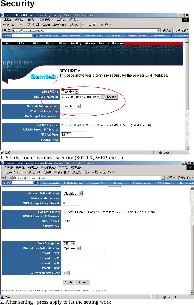
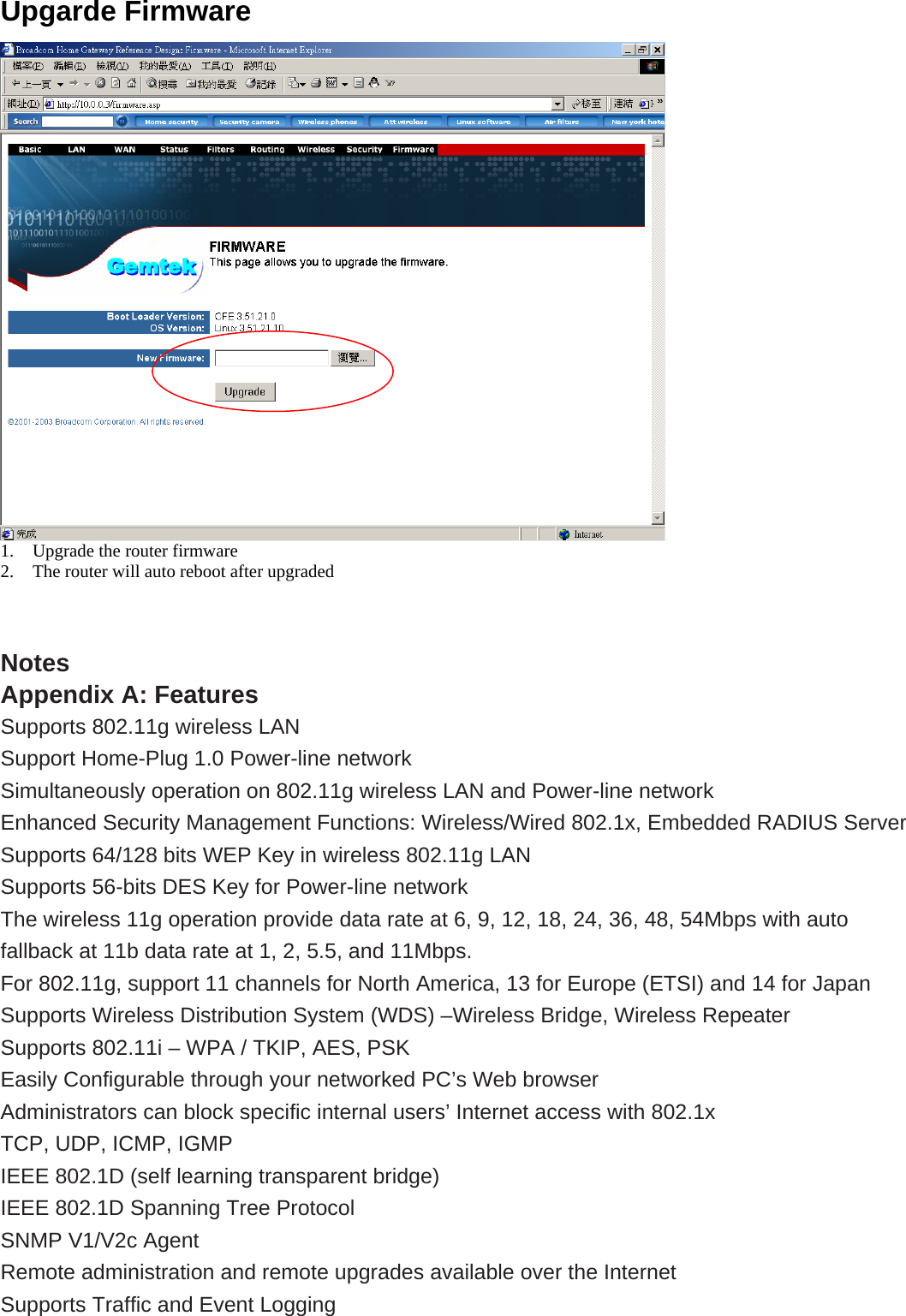
Users Manual
Navigation menu
Upload a User Manual
Namespaces
Wiki Guide
HTML
PDF
Info
Views
User Manual
Discussion / Help
Navigation