GemTek Technology ISA570 Cisco ISA570 Integrated Security Appliance with WiFi User Manual shiner admin guide
Gemtek Technology Co., Ltd. Cisco ISA570 Integrated Security Appliance with WiFi shiner admin guide
UserManual.wiki
>
GemTek Technology
>
ISA570 User Manual
User Manual
Navigation menu
Upload a User Manual
Namespaces
Wiki Guide
HTML
PDF
Info
Views
User Manual
Discussion / Help
Navigation


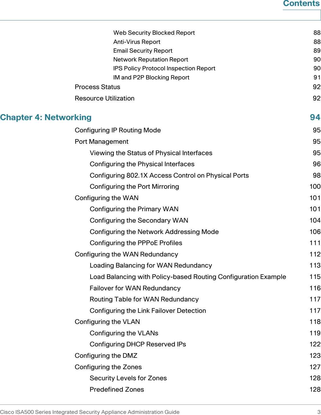
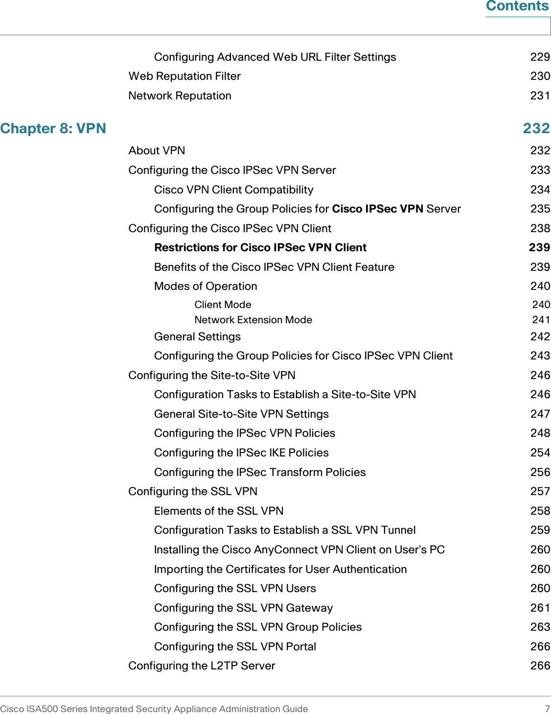
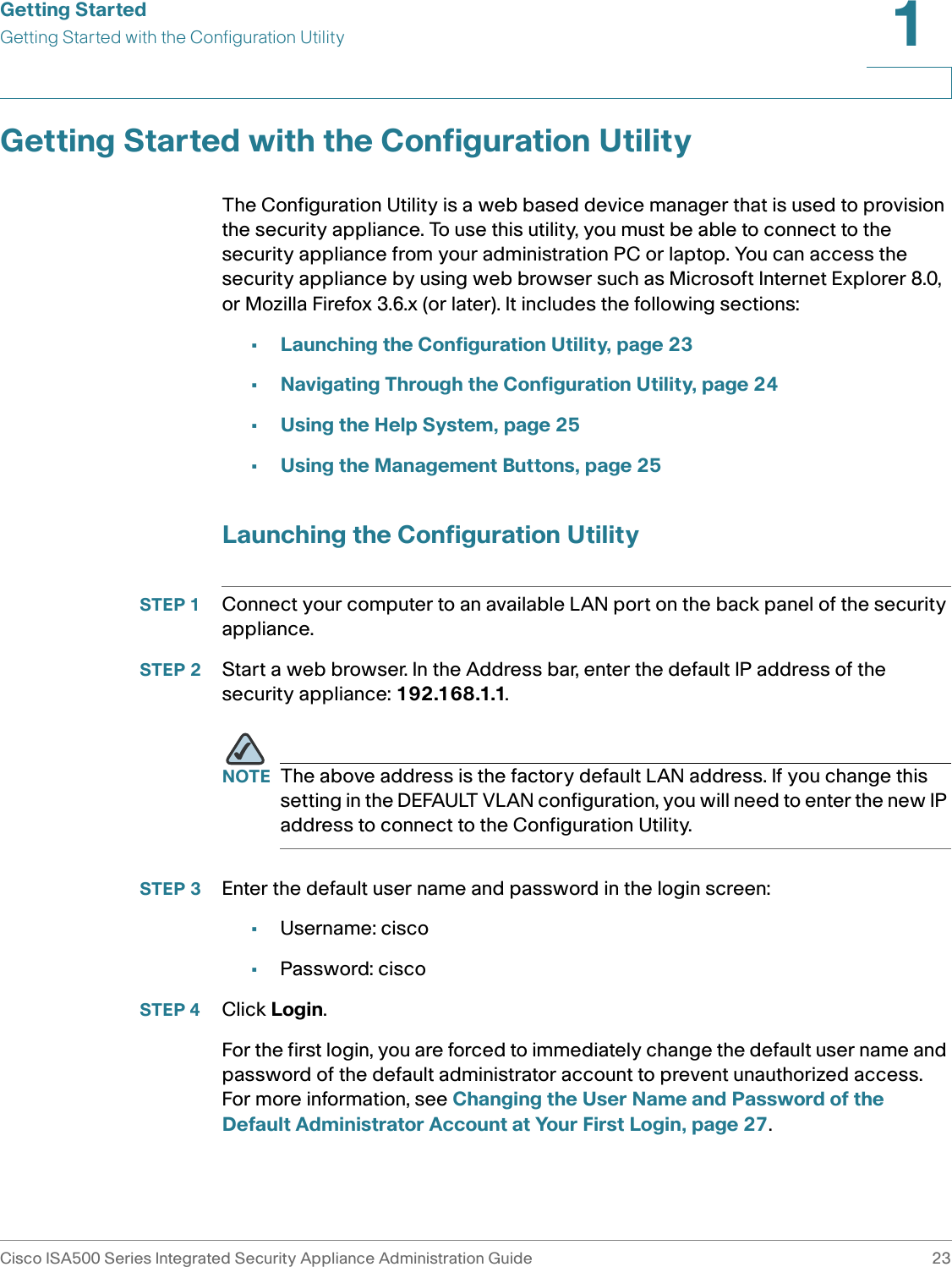
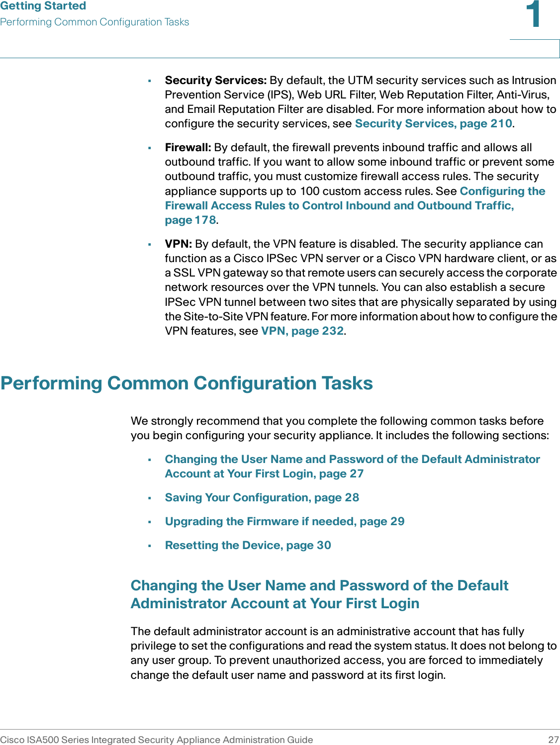
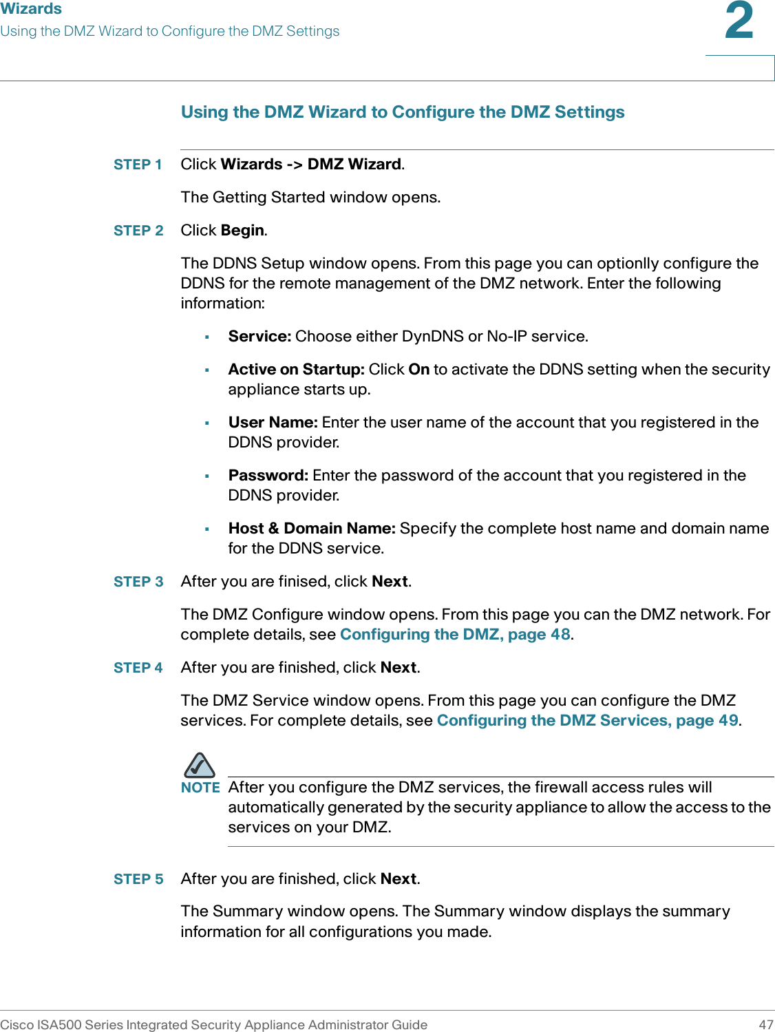
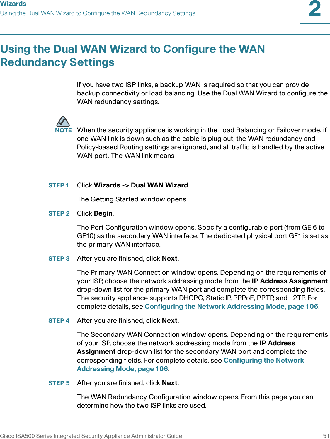
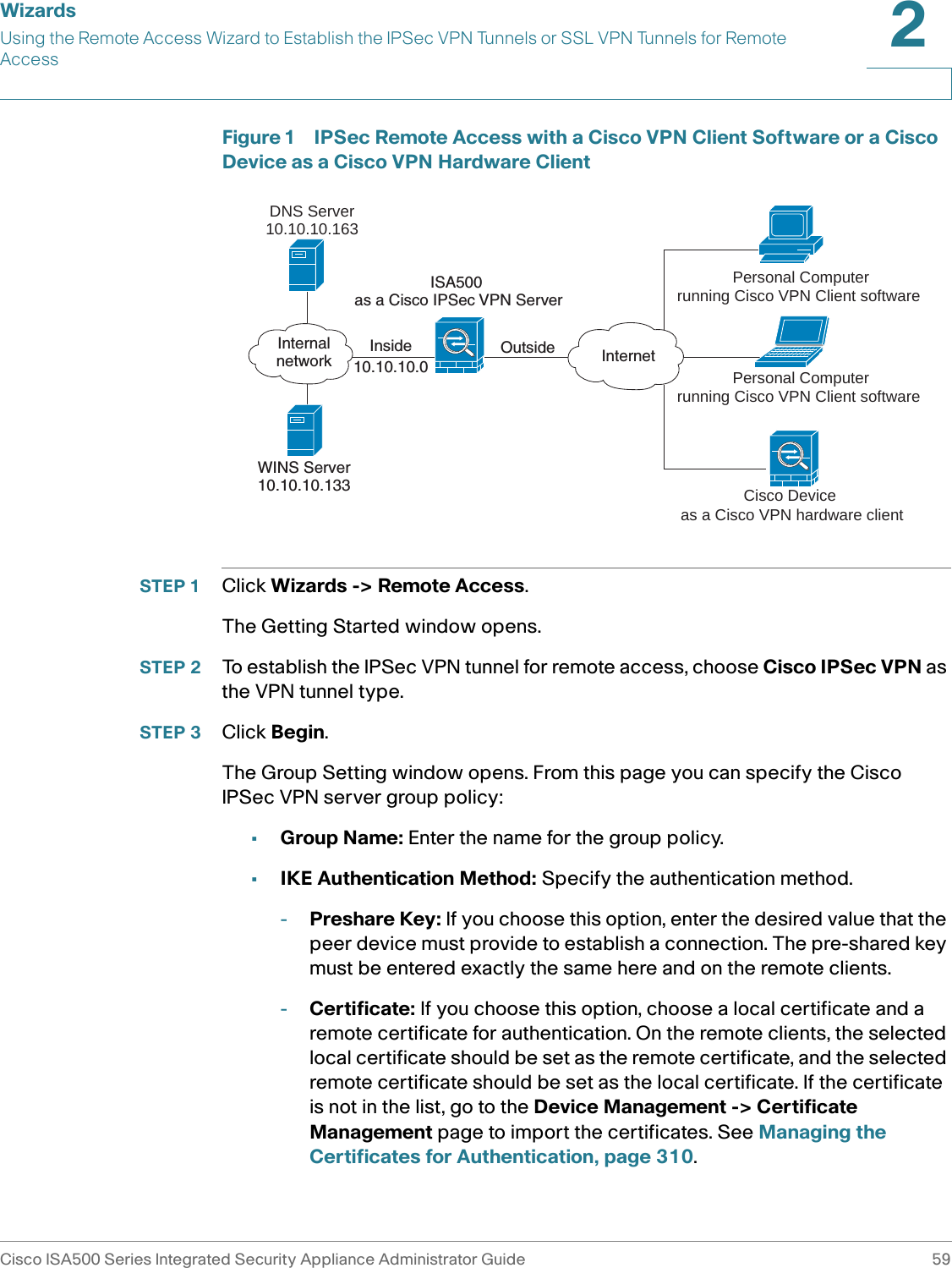
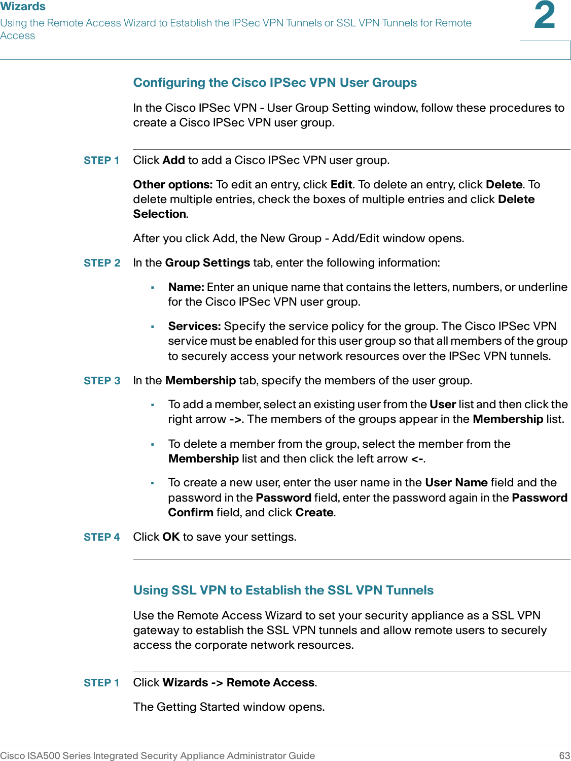


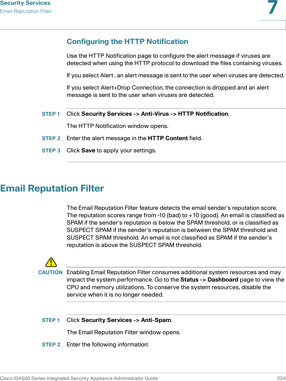
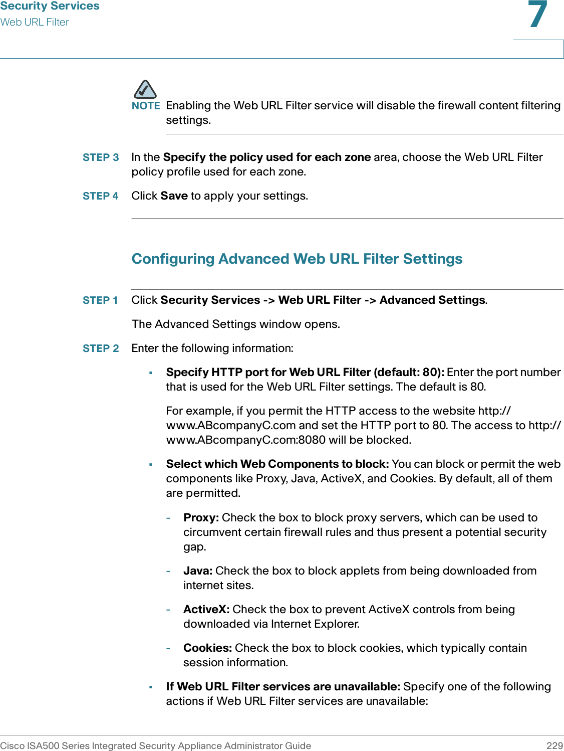
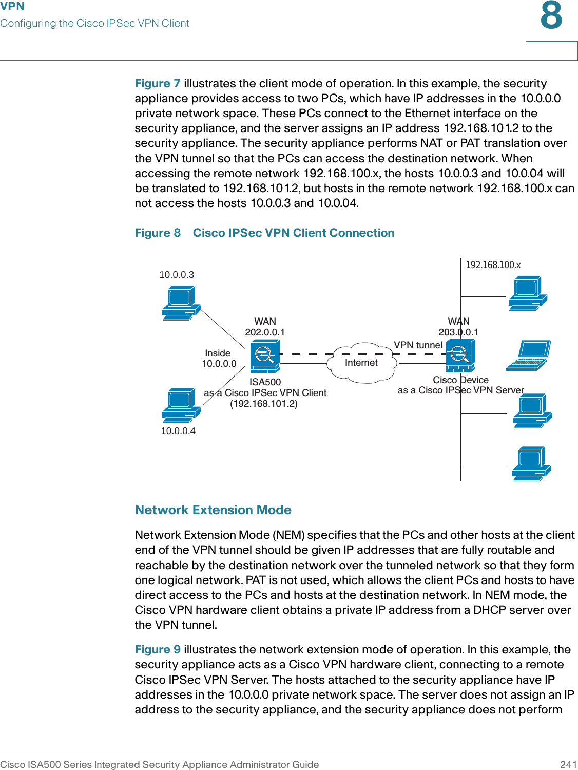
![Security ServicesAnti-VirusCisco ISA500 Series Integrated Security Appliance Administrator Guide 2237 Configuring the Email NotificationUse the Email Notification page to configure the tag and content message that are displayed in the alert email. The subject of the alert email will be tagged such as [Virus] Email Subject. If you select Alert for SMTP or POP3 protocol, when viruses are detected in the email, the original email and an alert email are sent to the email receiver. If you select Alert + Descruct File for SMTP or POP3 protocol, when viruses are detected in the email, the original email is destructed and an alert email is sent to the email receiver. STEP 1 Click Security Services -> Anti-Virus -> Email Notification. The Email Notification window opens. STEP 2 Enter the following information: •Email Alert Status: Shows if the Alert or Alert+Destruct File action is selected or not for SMTP or POP3 protocol.•From Email Address: The email address of the SMTP email account to send the alert email. •SMTP Server: The IP address or Internet name of the SMTP server. •SMTP Authentication: Shows if the SMTP authentication is enabled or disabled. NOTE The above email account settings are read only. They are used to send the alert emails to the original email receiver. Click the Email Alert Setting link to configure the email account settings. For more information, see Configuring the Email Alert Settings, page 316. •Mail Tag: Enter the tag that shows in the alert email ’s subject. The tag will insert to the alert email subject in the [Tag] Email Subject format. •Mail Content: Enter the content that appears in the alert email. STEP 3 Click Save to apply your settings.](https://usermanual.wiki/GemTek-Technology/ISA570/User-Guide-1477211-Page-229.png)
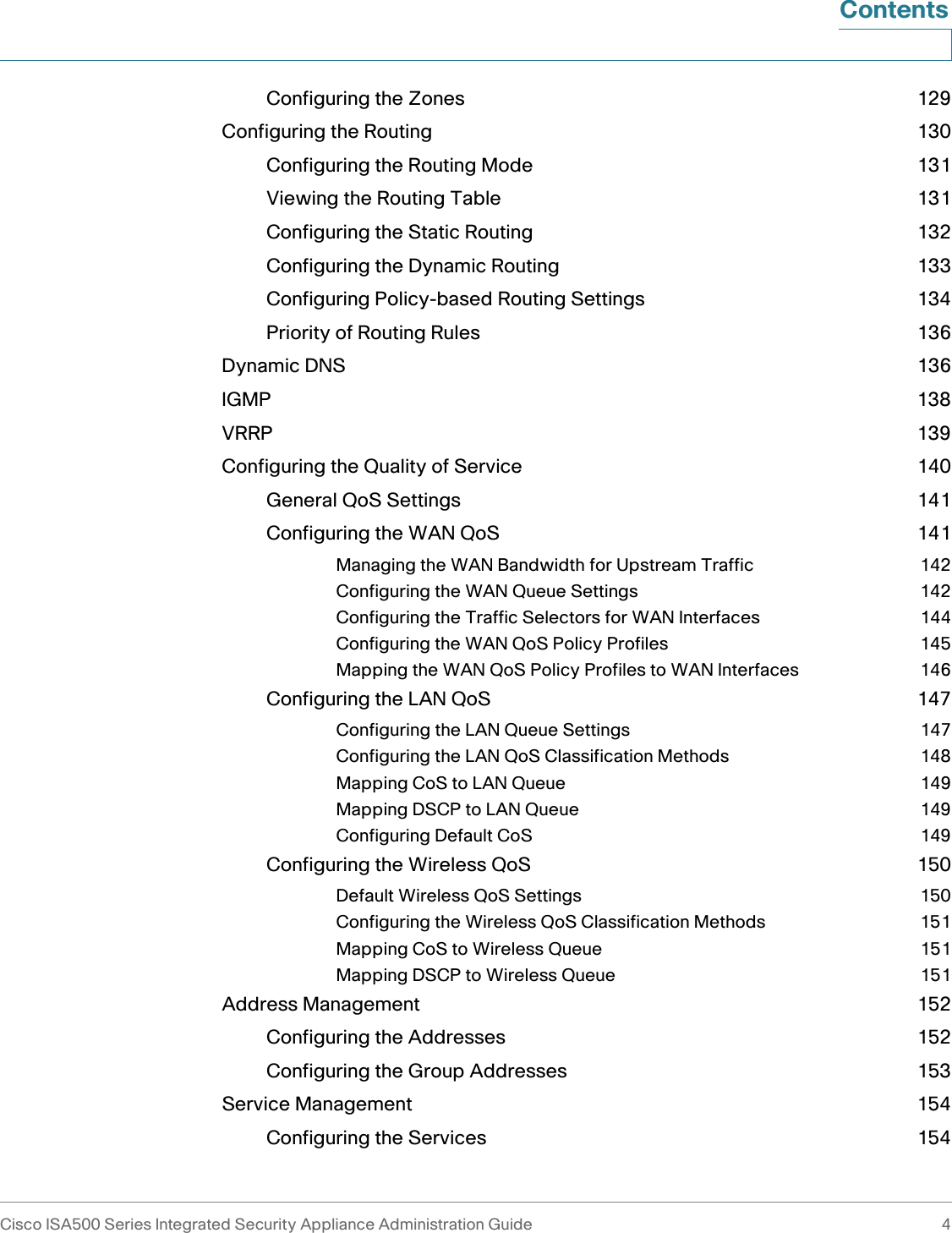
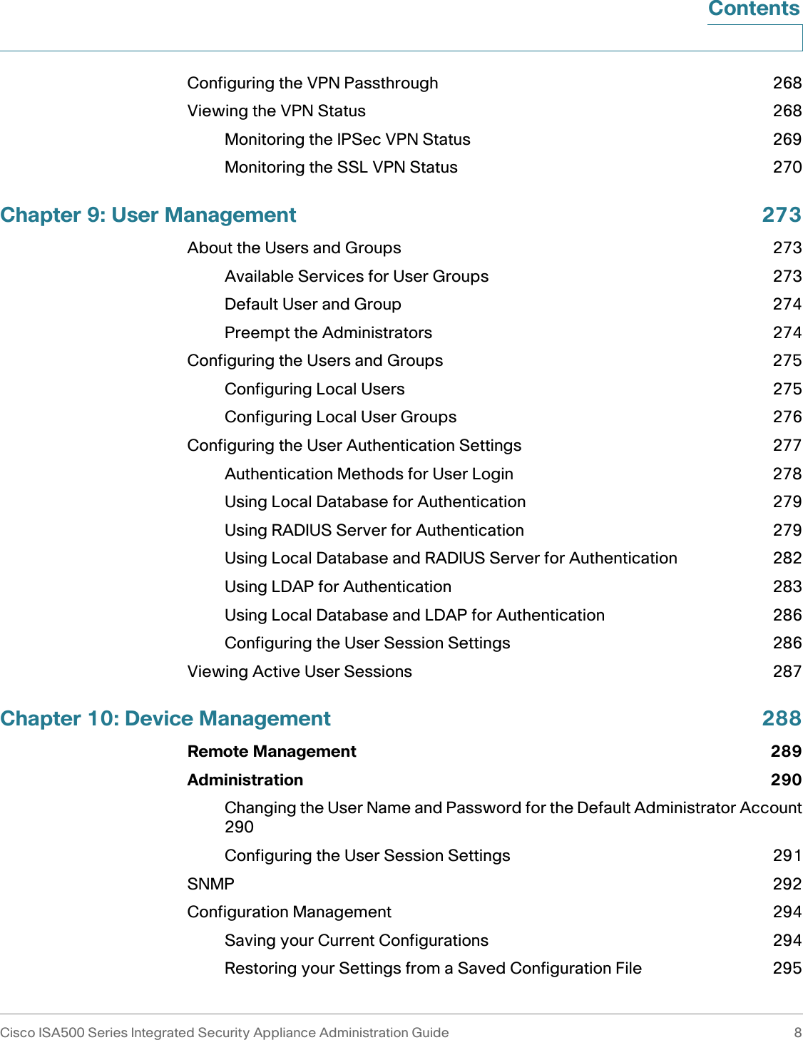
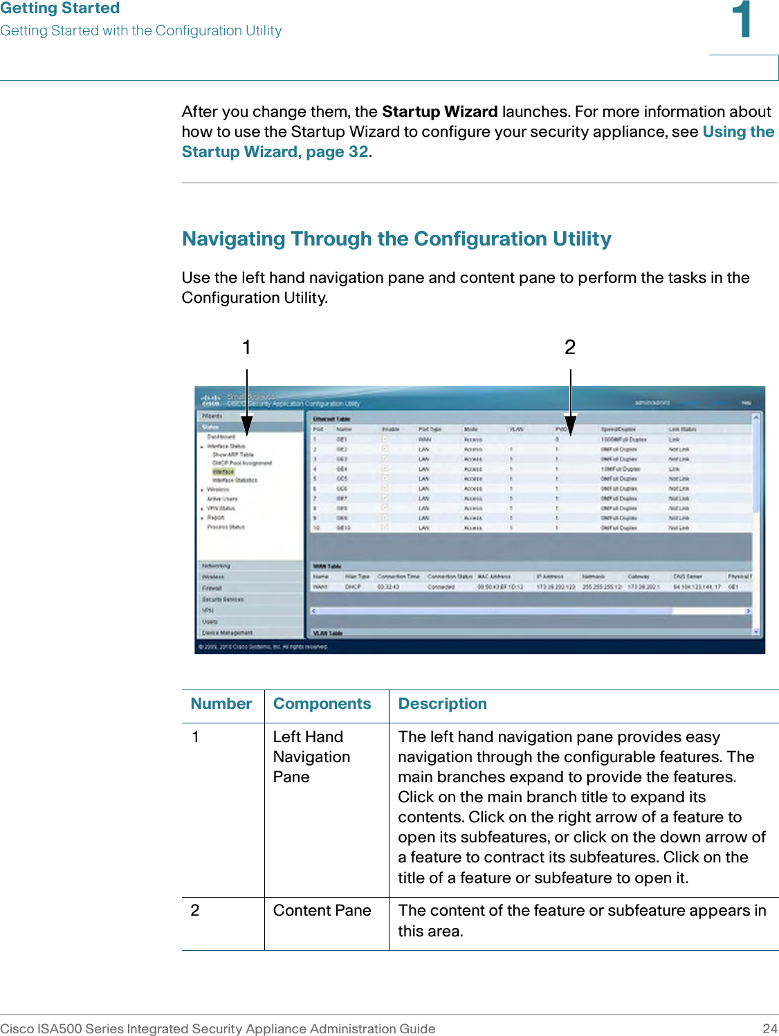
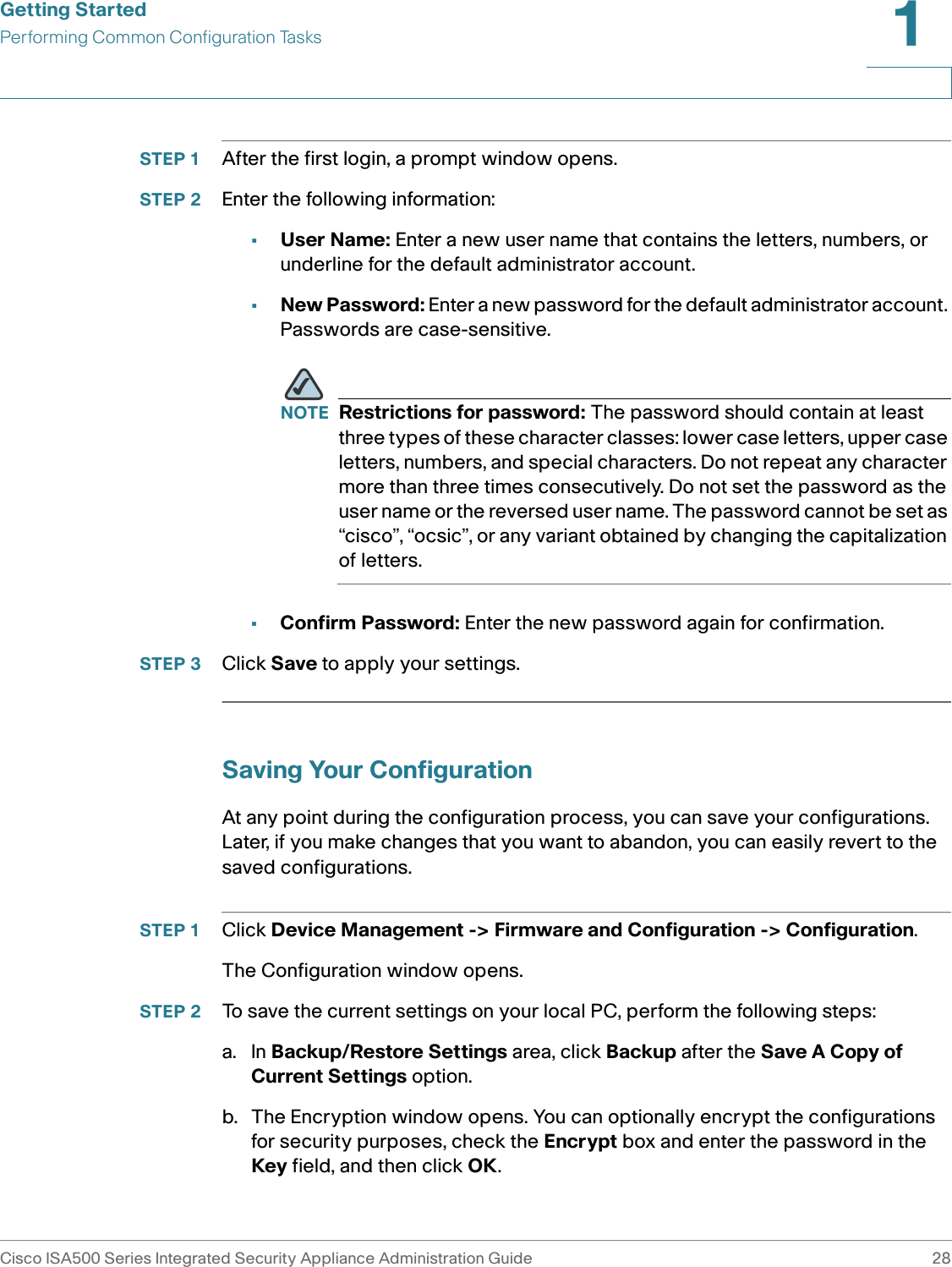
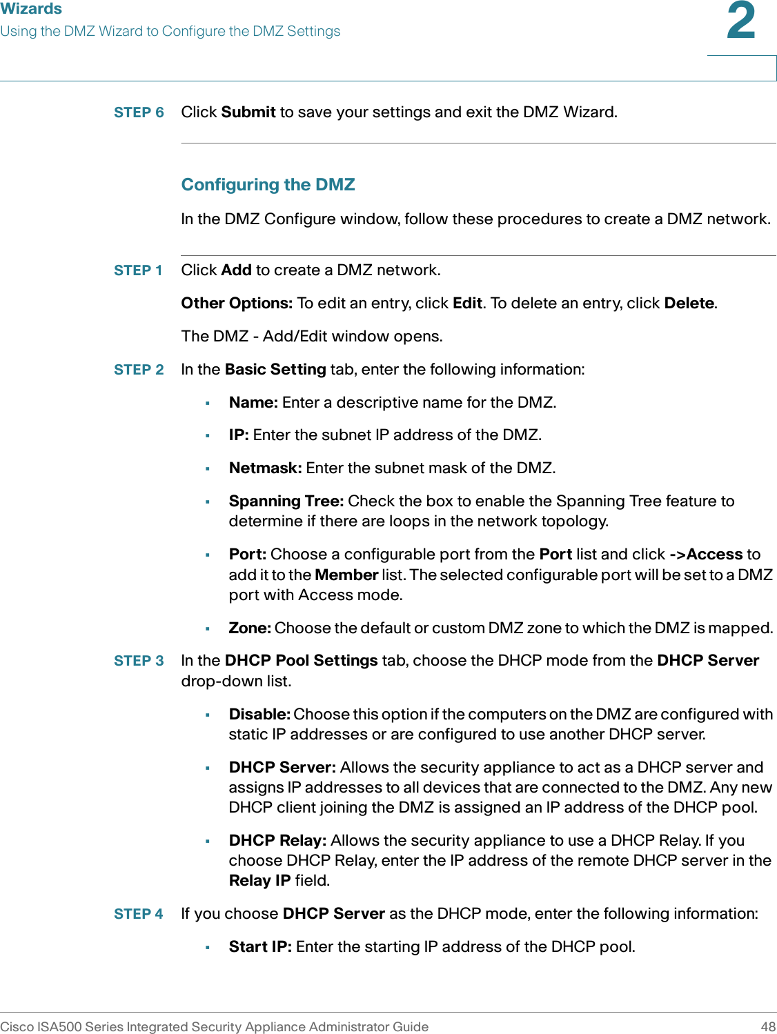
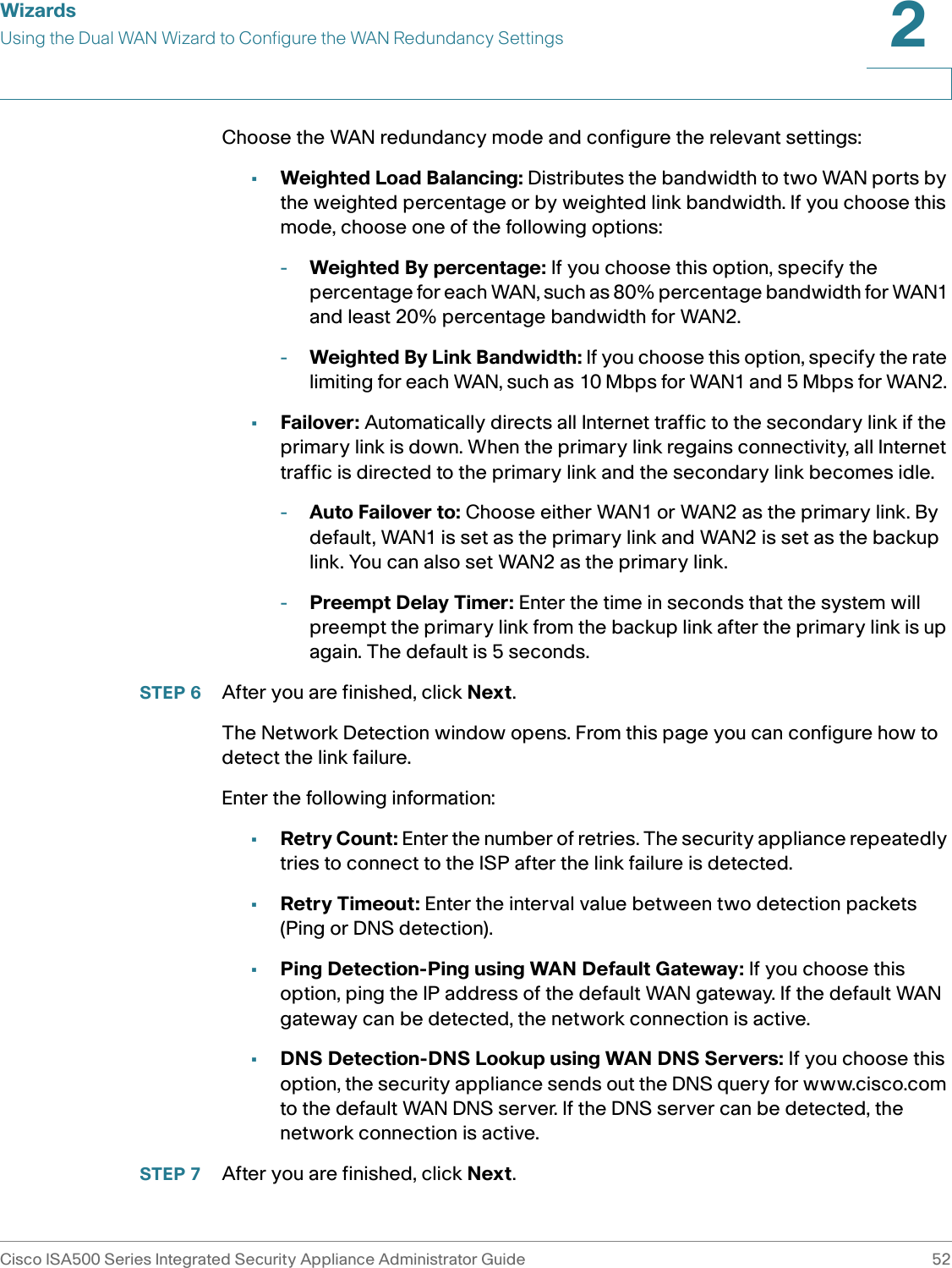
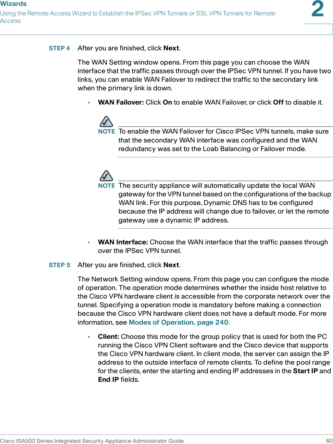
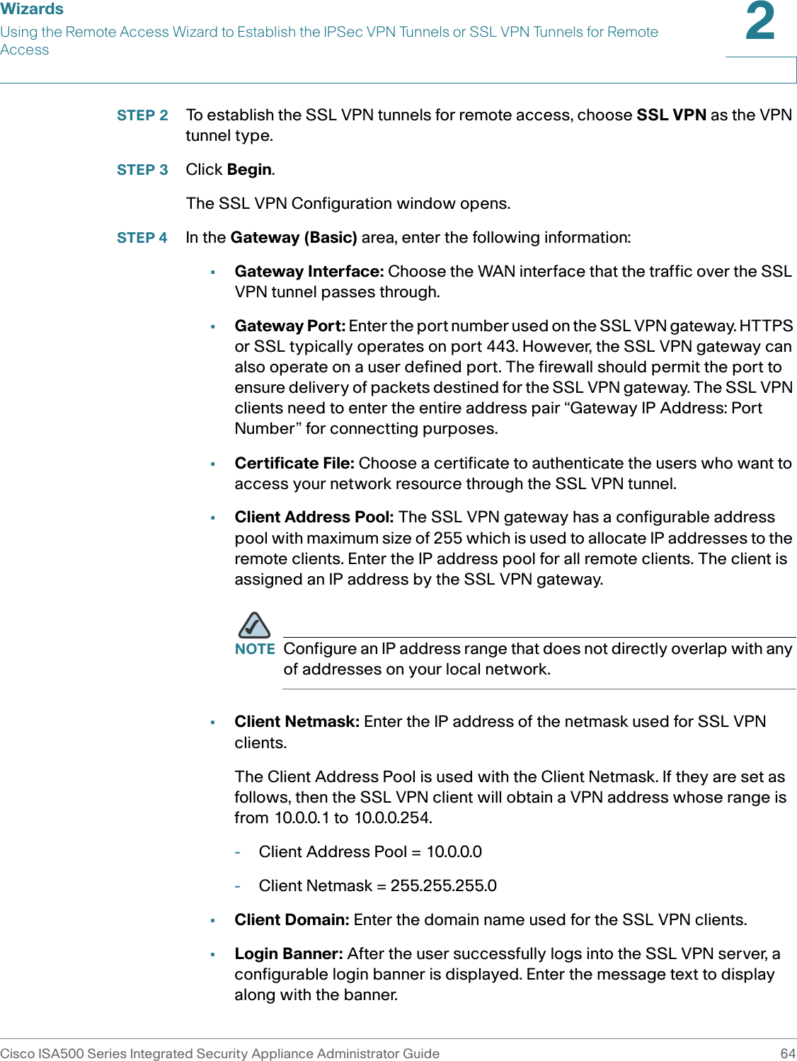
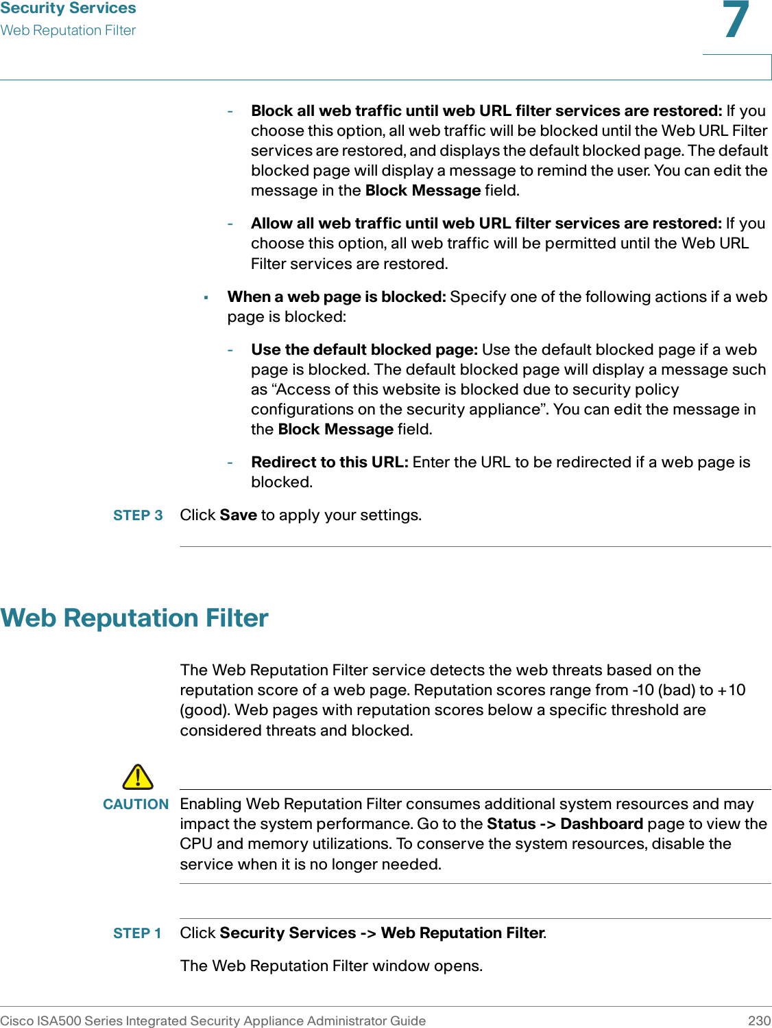
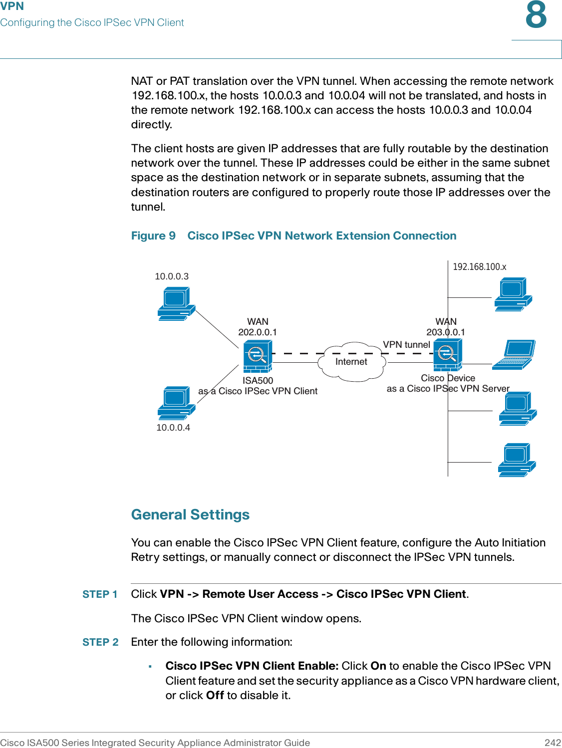
![Security ServicesEmail Reputation FilterCisco ISA500 Series Integrated Security Appliance Administrator Guide 2257 •Enable Anti-Spam Filter: Click On to enable Email Reputation Filter, or check Off to disable it. •SMTP Server Address: Enter the address of the SMTP server. •Choose Reputation Threshold: Specify the block sensitivity as either Conservative, Moderate or Aggressive, or as a numerical threshold (Custom). When the Custom radio button is selected, the drop-down lists next to it are enabled allowing the threshold values to be entered. The allowable values for the threshold are integers from -10 to -1 and the value -0.5.The Email Reputation Filter detects spam emails based on the reputation score of the sender’s IP address. The sender’s address is the address that initiated the connection to the SMTP server, not an address within the email header. STEP 3 Specify the actions for SPAM and SUSPECT SPAM emails: •Action for SPAM Is: Choose Block to block the email, or choose TAG to get the email tagged with [SPAM].•Action for SUSPECT SPAM Is: Choose Block to block the email, or choose TAG to get the email tagged with [SUSPECT SPAM].STEP 4 Choose one of the following actions if the Email Reputation Filter service is unavailable: •Do not accept any emails until reputation services are restored (emails will be delayed): If you choose this option, all emails will be delayed until the Email Reputation Filter service is restrored.•Deliver all emails without checking for spam: If you choose this option, you can deliver all emails without checking for spam. This is the default setting if Email Reputation Filter service is unavailable.STEP 5 Click Save to apply your settings.](https://usermanual.wiki/GemTek-Technology/ISA570/User-Guide-1477211-Page-231.png)
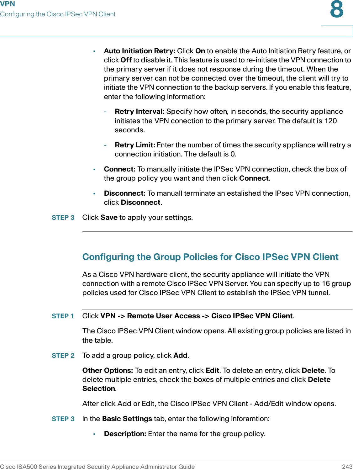
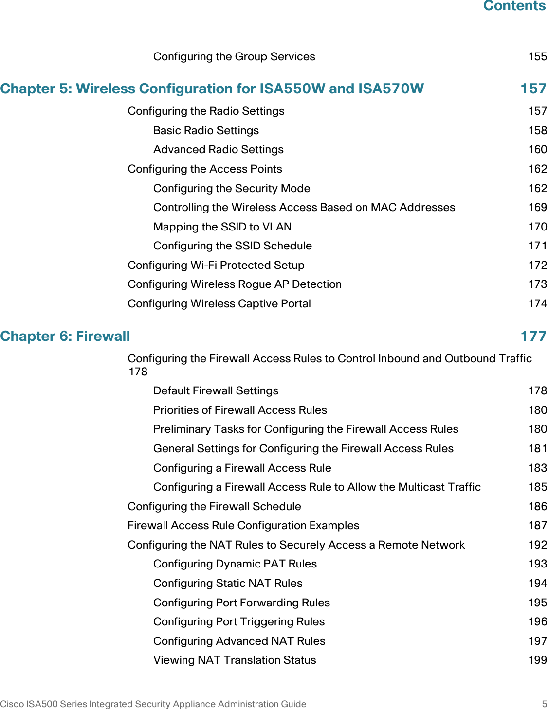
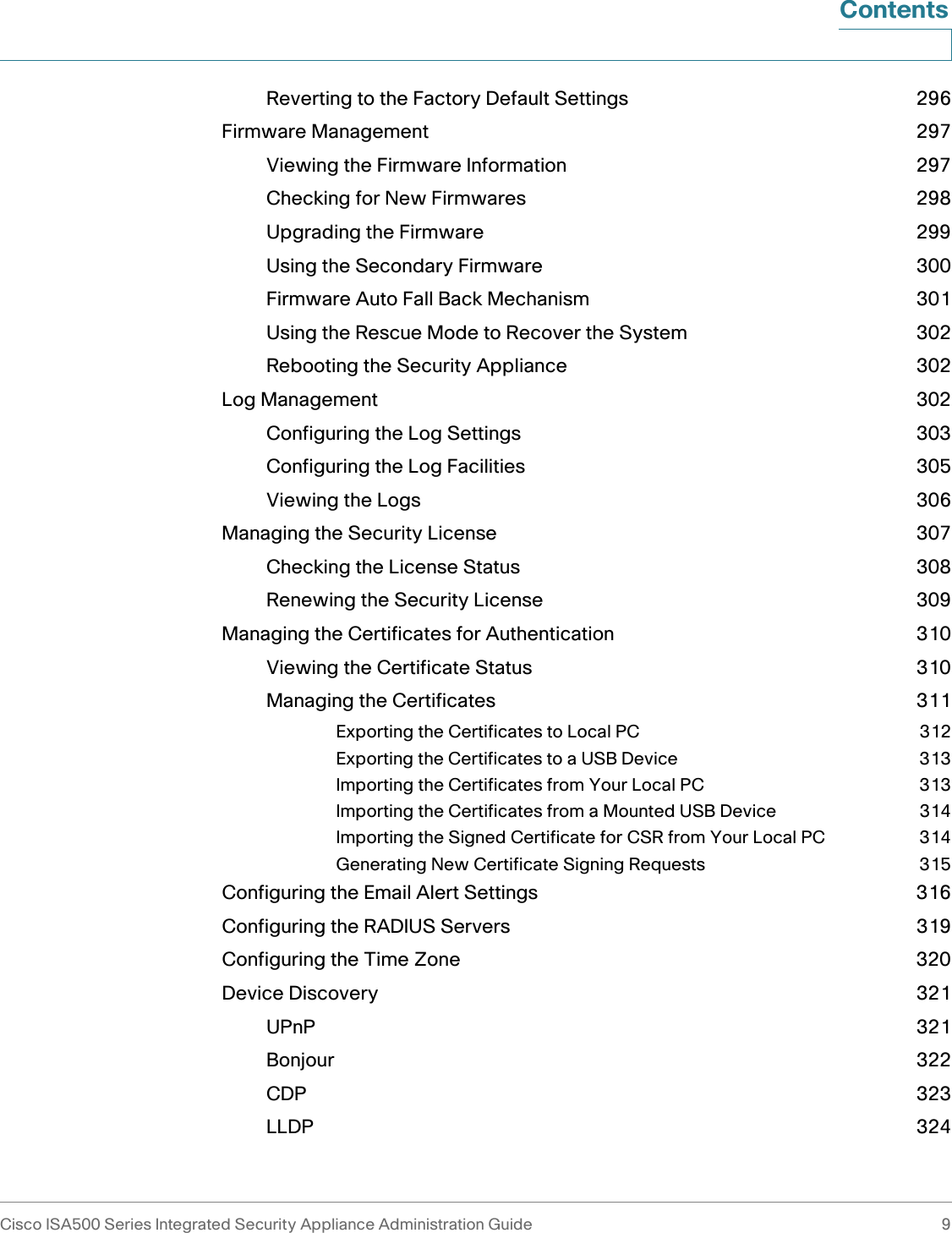
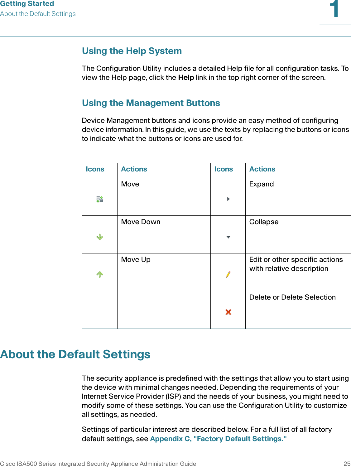
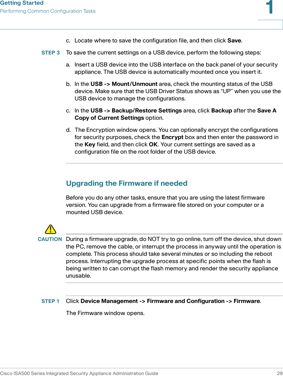
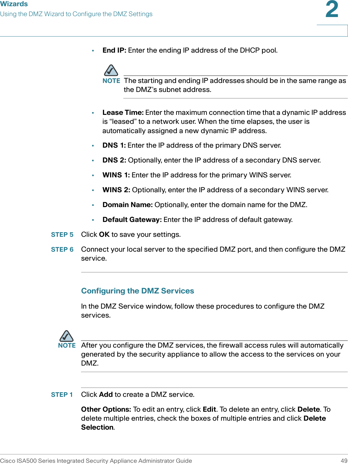
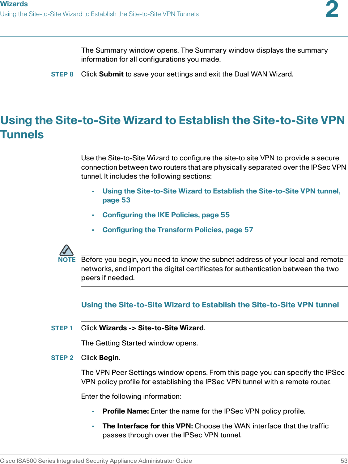
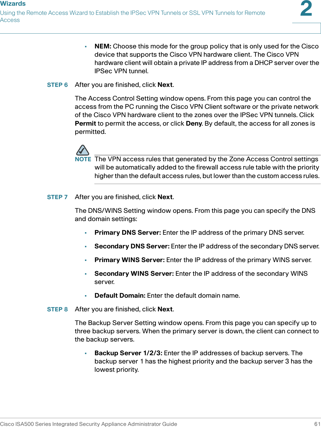
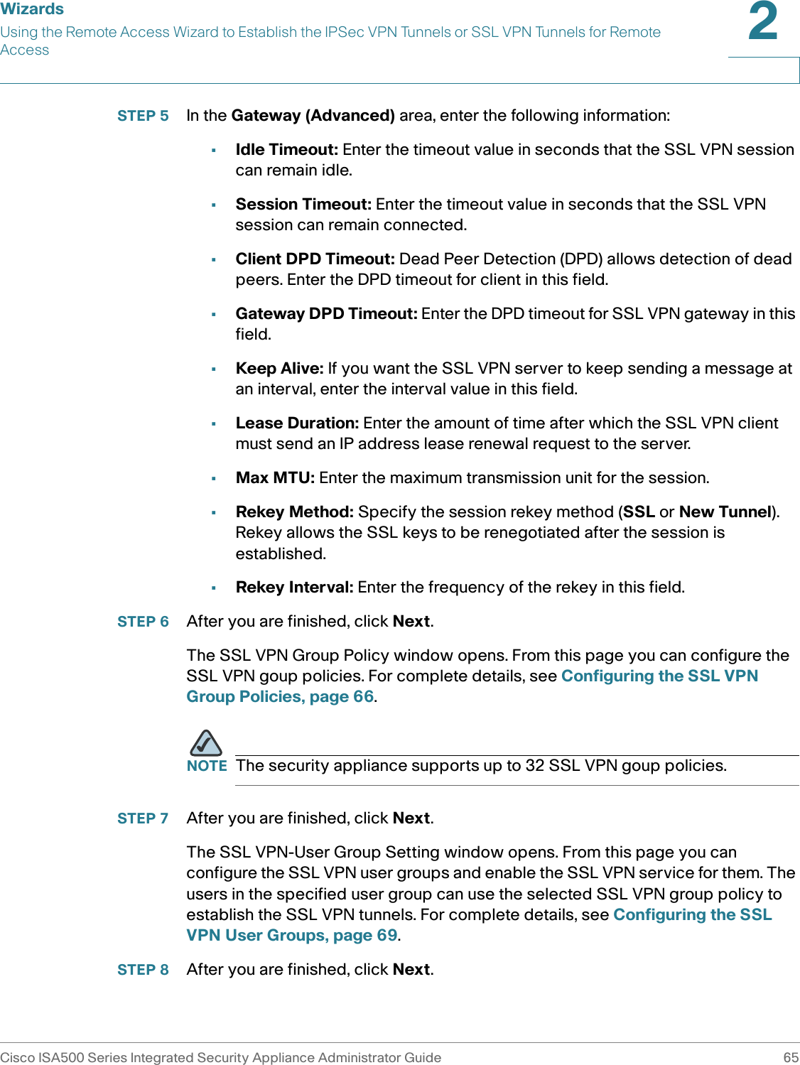
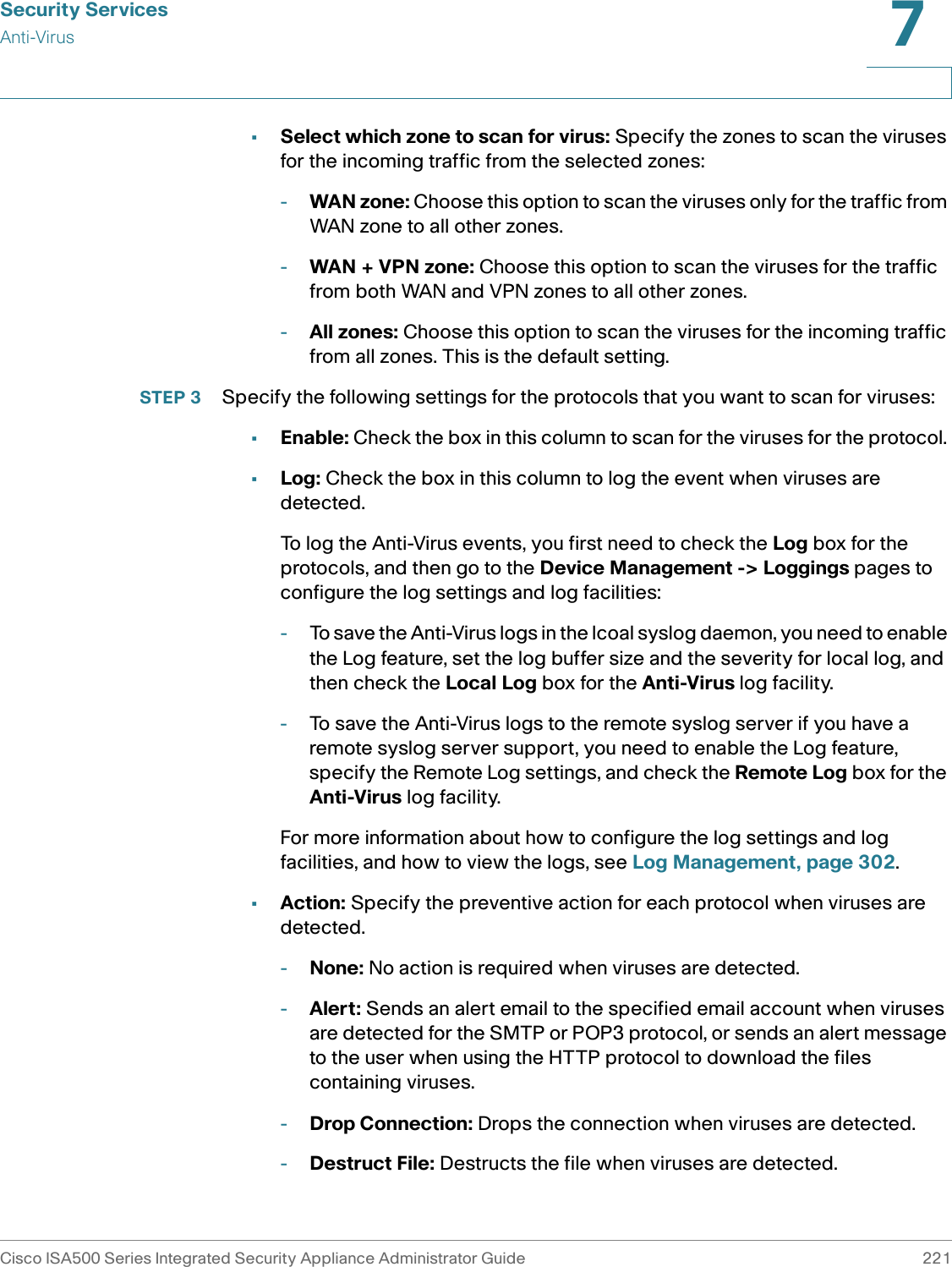
![Factory Default SettingsFirewallCisco ISA500 Series Integrated Security Appliance Administrator Guide 358C Maximum number of custom firewall rules100NATDynamic PAT enableMaximum number of Static NAT rules128Maximum number of Port Forwarding rules15Maximum number of Port Triggering rules15 Maximum number of Advanced NAT rules16Session SettingsMaximum number of Connections60000 (1000 to 60000)TCP Timeout 1200 (5 to 3600)UDP Timeout 180 (5 to 3600)Attack ProtectionBlock Ping WAN interface enableEnable Stealth Mode disableBlock TCP Flood (Threshold: 200 per seconds)disableBlock UDP Flood (Threshold: 200 per seconds)disableBlock ICMP Notification enableBlock Fragmented Packets disableBlock Muticast Packets disableSYN Flood Detect Rate [max/sec]0 (0 to 65535)Features Settings](https://usermanual.wiki/GemTek-Technology/ISA570/User-Guide-1477211-Page-364.png)
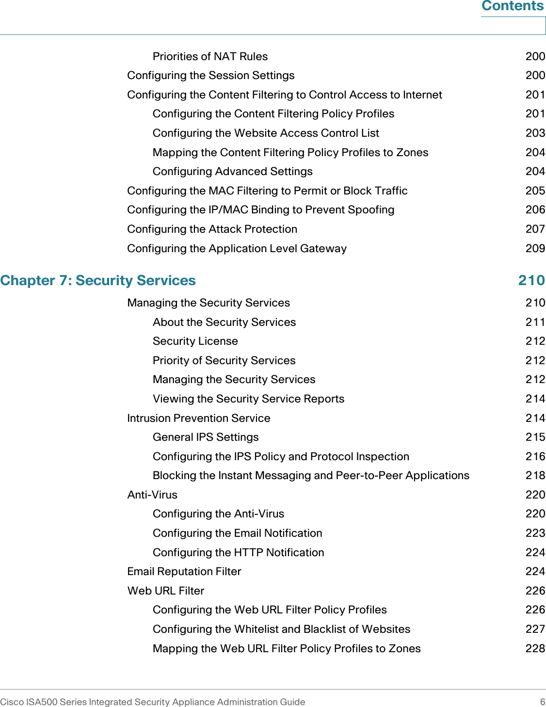
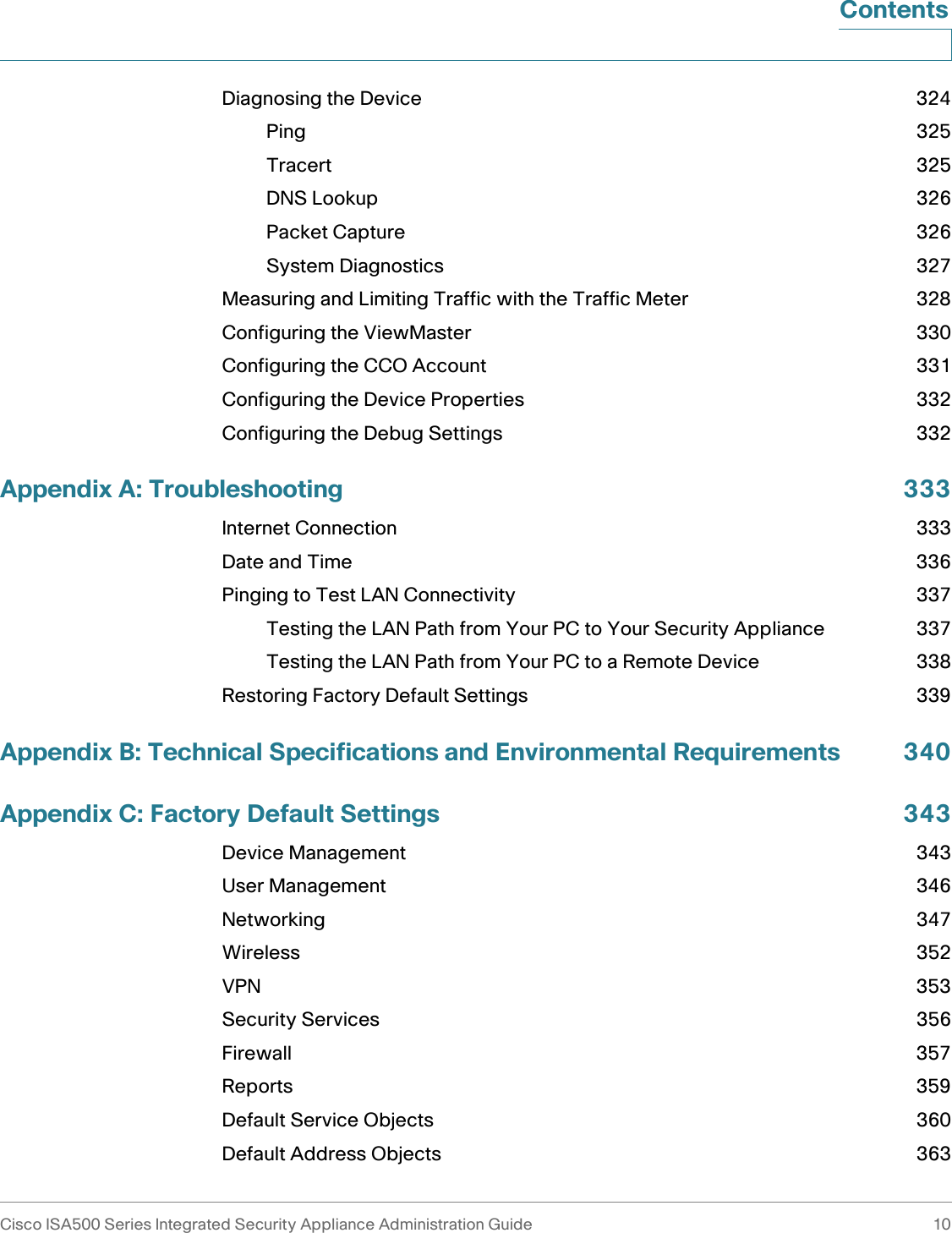
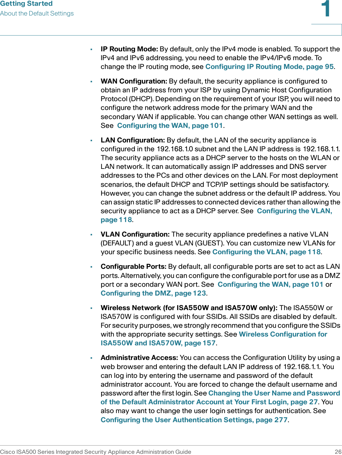
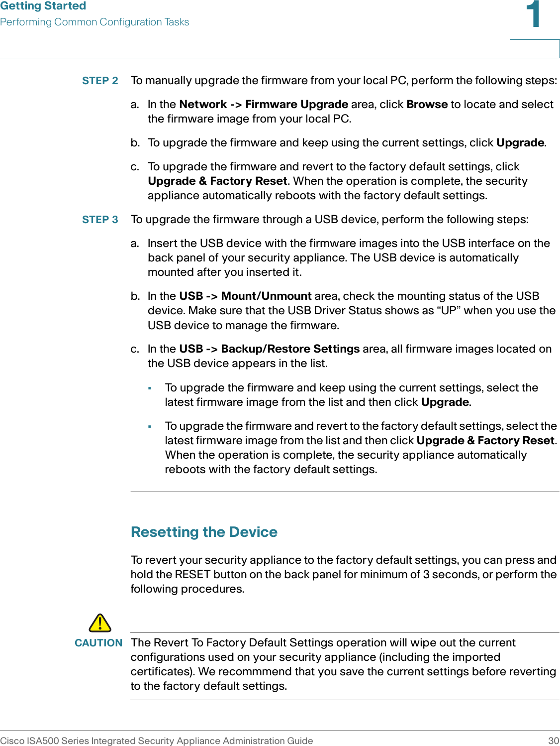
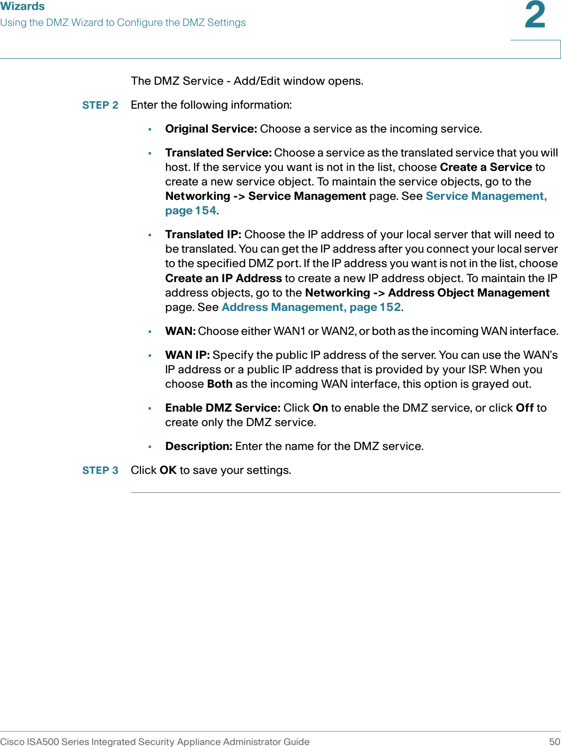
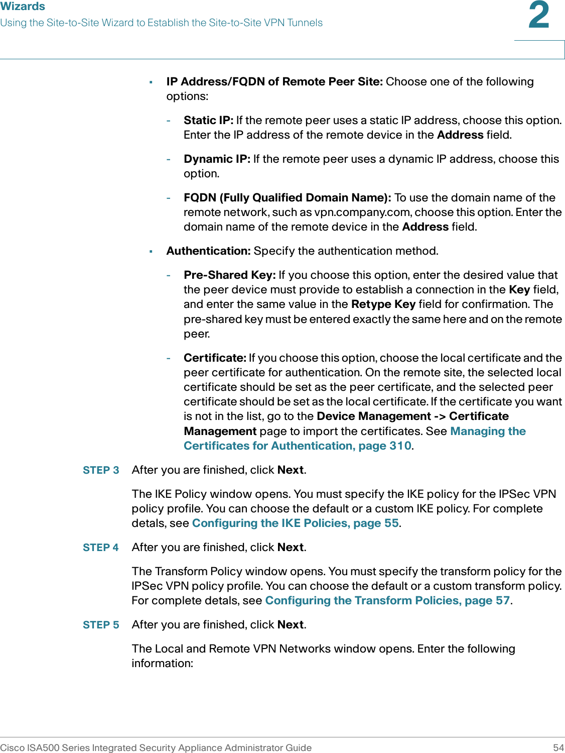
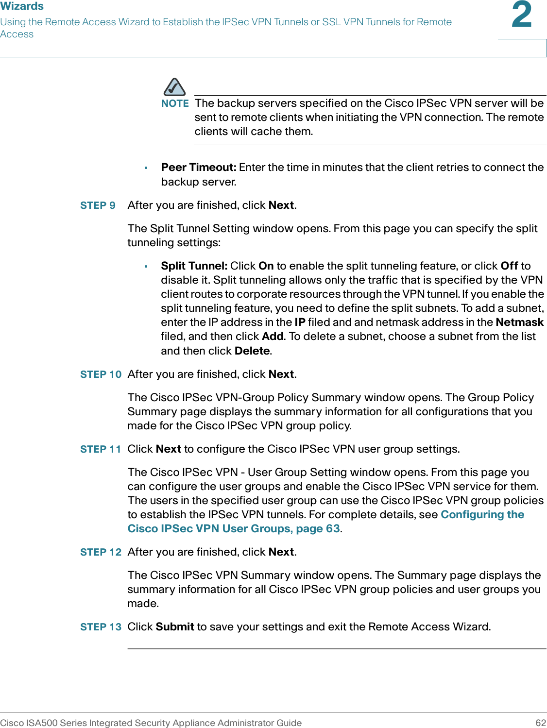
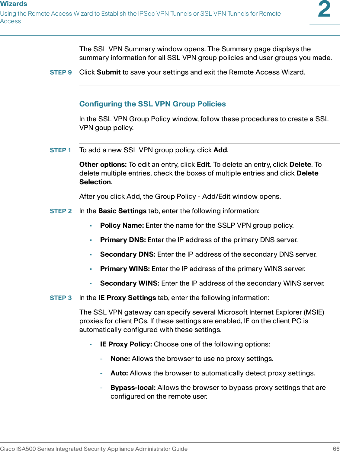
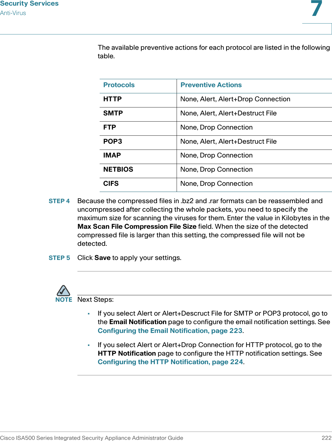
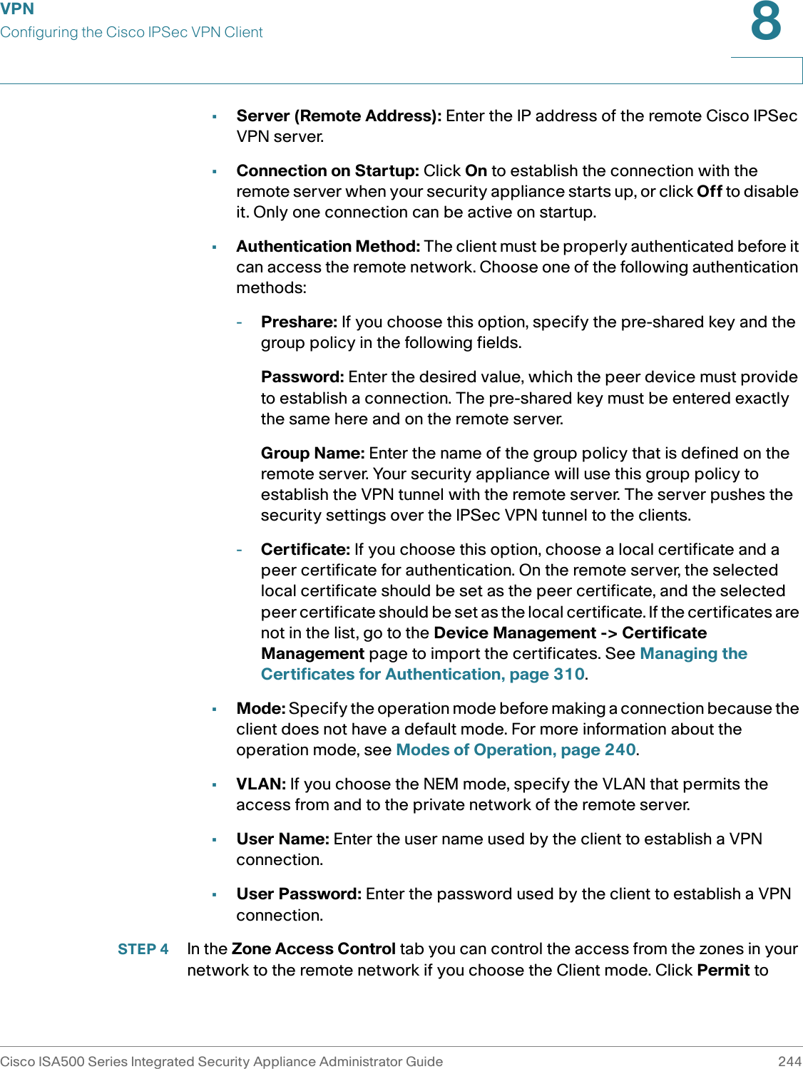
![Factory Default SettingsReportsCisco ISA500 Series Integrated Security Appliance Administrator Guide 359C ReportsEcho Storm [ping pkts./sec] 0 (0 to 65535)ICMP Flood [ICMP pkts./sec] 0 (0 to 65535)Application Level Gateway enableSIP ALG enableH.323 ALG enableContent Filtering disableHTTP port for content filtering80Permit or block web components (Proxy, Java, ActiveX, Cookies)permitMAC Filtering disableMaximum number of MAC Filtering rules100Maximum number of IP&MAC Binding rules100Features SettingsFeature SettingsIP Bandwidth Report disableService Bandwidth Report disableTopN Web Report disableWAN Bandwidth Report disableSecurity Service ReportsNetwork Reputation Report enable](https://usermanual.wiki/GemTek-Technology/ISA570/User-Guide-1477211-Page-365.png)