GemTek Technology P980430N 7130 Residential Gateway 6Ve.A2130 User Manual 6Ve A2130 UM
Gemtek Technology Co., Ltd. 7130 Residential Gateway 6Ve.A2130 6Ve A2130 UM
UserManual.wiki
>
GemTek Technology
>
P980430N User Manual
>
Manual 1
Contents
1.
Manual 1
2.
Manual 2
Manual 1
Navigation menu
Upload a User Manual
Namespaces
Wiki Guide
HTML
PDF
Info
Views
User Manual
Discussion / Help
Navigation

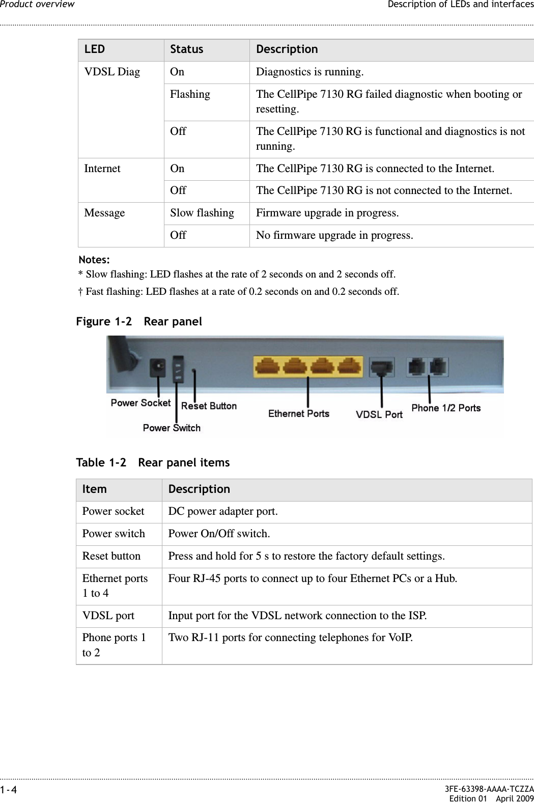
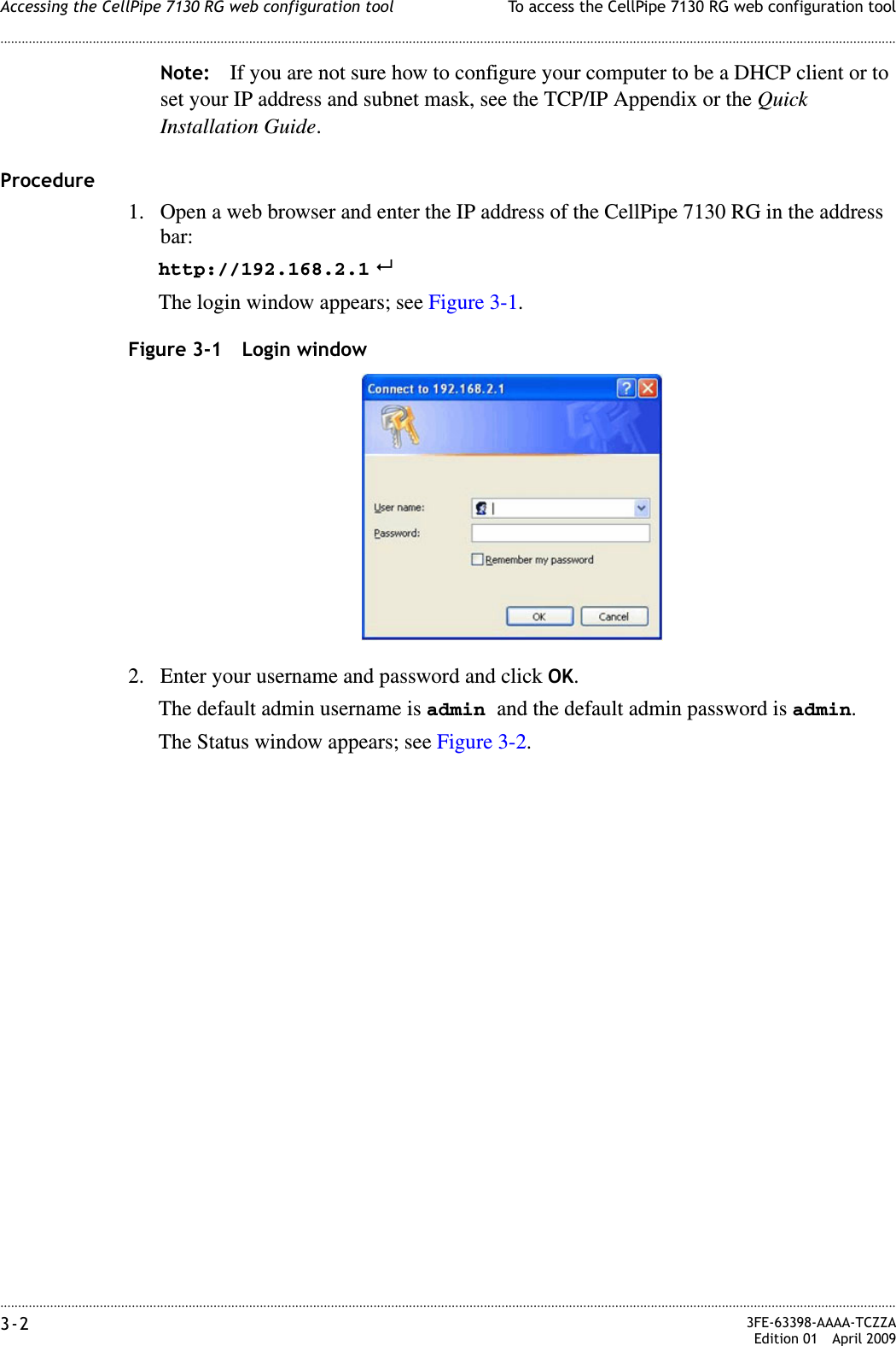


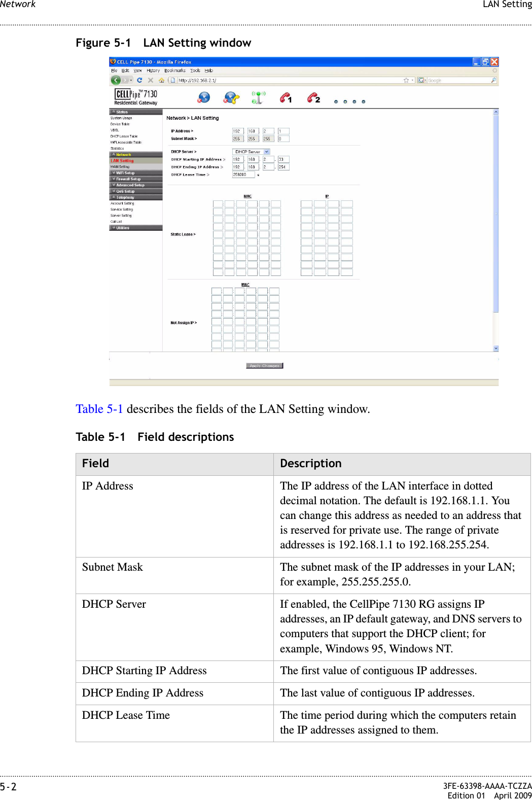
![............................................................................................................................................................................................................................................................WAN Settin gNetwork5-6 3FE-63398-AAAA-TCZZAEdition 01 April 2009............................................................................................................................................................................................................................................................Table 5-3 Field descriptions Fields Description[PPPoE#1] to [PPPoE#2] Enable one or both of the supported VLAN over PPPoE.VLANUntagged Enable if a VLAN ID is not being used.Always Use ID Enable if a VLAN ID is being used and enter the ID number (between 2 to 4094).Priority Enter a priority level from 0 to 7 to define user priority.User Name Enter the user name for the PPPoE connection.Password Enter the password for the PPPoE connection.Access Concentrator The access concentrator is optional. Consult with your ISP for information.Service Name The service name is optional. Consult with your ISP for information.ModeConnect on demand: Max idle time Select to have the router connect to the Internet only when you choose to do so. Enter a max idle time to specify the maximum number of idle seconds after which the connection is dropped.Always on Select to always have the router connect to the Internet.Manual Select and then click Connect to manually connect the router to the internet. Click Disconnect to end the connection.OptionsAuthentication Mode Select the authentication mode from the drop-down menu. Options include:•CHAP + PAP•CHAP•PAPThis is optional. Your ISP will provide this information if it is necessary.MTU (bytes) Enable Auto to set the maximum transfer unit to the default (1492), or enable Manual to manually enter a unit.Apply Changes Click to save your changes.](https://usermanual.wiki/GemTek-Technology/P980430N.Manual-1/User-Guide-1127882-Page-34.png)