GemTek Technology P980430N 7130 Residential Gateway 6Ve.A2130 User Manual 6Ve A2130 UM
Gemtek Technology Co., Ltd. 7130 Residential Gateway 6Ve.A2130 6Ve A2130 UM
Contents
- 1. Manual 1
- 2. Manual 2
Manual 1

CellPipe® 7130
Residential Gateway
6Ve.A2130, 6Ve.B2130 | Release 01
USER MANUAL
3FE-63398-AAAA-TCZZA
EDITION 01
APRIL 2009
Alcatel, Lucent, Alcatel-Lucent, the Alcatel-Lucent logo, and CellPipe are trademarks of Alcatel-Lucent. All other trademarks are the property of their
respective owners.
The information presented is subject to change without notice. Alcatel-Lucent assumes no responsibility for inaccuracies contained herein.
Alcatel-Lucent provides this documentation without warranty of any kind, implied or expressed, including, but not limited to, the implied warranties of
merchantability and fitness for a particular purpose.
Copyright © 2009 Alcatel-Lucent. All rights reserved.
Conformance statements
The equipment has been tested in the regulation lab and complied with the limits for SHDSL device, pursuant to Europe CE/CB, Australia A-Trick and China
CCC. These limits of different regulations are designed provide reasonable protection against harmful interference or damage in a residential installation.
Security statement
In rare instances, unauthorized individuals make connections to the telecommunications network through the use of remote access features. In such an event,
applicable tariffs require the customer to pay all network charges for traffic. Alcatel-Lucent cannot be responsible for such charges and will not make any
allowance or give any credit for charges that result from unauthorized access.
IMPORTANT NOTICE: This document contains confidential information that is proprietary to Alcatel-Lucent. No part of its contents may be used, copied,
disclosed or conveyed to any party in any manner whatsoever without prior written permission from Alcatel-Lucent.
www.alcatel-lucent.com

i
3FE-63398-AAAA-TCZZA
Edition 01 April 2009
............................................................................................................................................................................................................................................................
About this document
Purpose
This document provides information on the hardware setup, software configuration, and
administration necessary to operate the CellPipe 7130 Residential Gateway 6Ve.A2130
and 6Ve.B2130.
Reason for revision
The following table shows the revision history of this document.
Intended audience
This document is intended for users and administrators of the CellPipe 7130 RG
6Ve.A2130 and 6Ve.B2130.
How to use this document
This document introduces the CellPipe 7130 RG 6Ve.A2130 and 6Ve.B2130 hardware,
connections, and setup. It also covers the Web configuration interface and provides
parameter definitions for the fields on those screens.
Conventions used
This guide uses the following typographical conventions:
Revision Date Reason for reissue
Edition 01 April 2009 First release of this document
Appearance Description
Italicized text •File and directory names.
•Emphasized information.
•Titles of publications.
•A value that the user supplies.
graphical user interface text or
key name
•Text that is displayed in a graphical user
interface or in a hardware label.
•The name of a key on the keyboard.
............................................................................................................................................................................................................................................................
About this document
ii 3FE-63398-AAAA-TCZZA
Edition 01 April 2009
............................................................................................................................................................................................................................................................
Structure of hazard statements
Overview
For the safety of you and your equipment, this document contains hazard statements.
Hazard statements are given at points where there may be a risk of damage to personnel,
equipment, or operation. Failure to follow the directions in a hazard statement may result
in personal harm, equipment damage, or network loss.
General structure
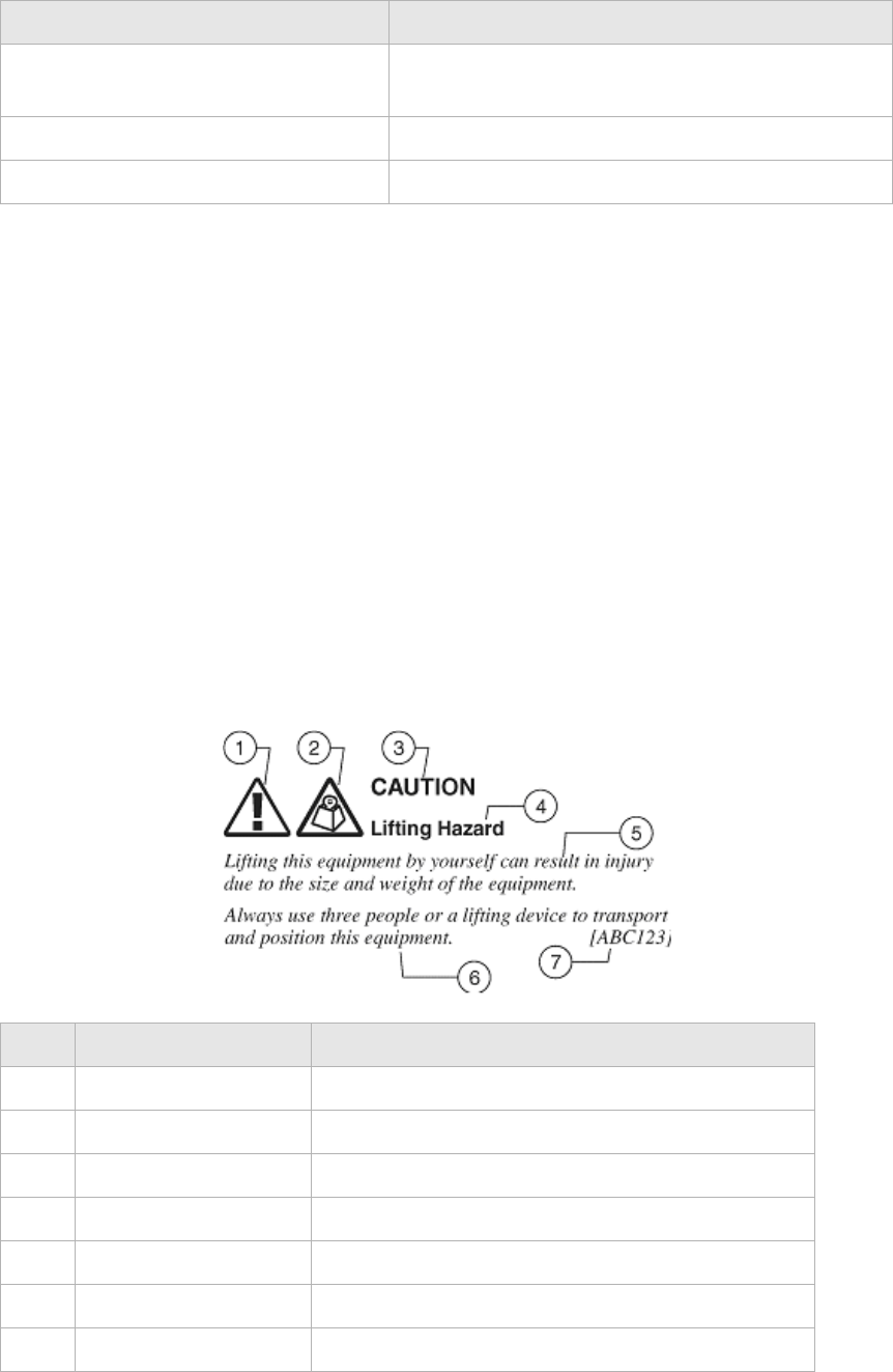
Hazard statements include the structural elements shown in the figure below.
Structure of hazard statements
input text Command names and text that the user types or
selects as input to a system.
output text Text that a system displays or prints.
!Press the Return or Enter key on the keyboard.
Appearance Description
Item Structure element Purpose
1 Personal injury symbol Indicates the potential for personal injury (optional).
2 Hazard type symbol Indicates hazard type (optional).
3 Signal word Indicates the severity of the hazard.
4 Hazard type Describes the source of the risk of damage or injury.
5 Damage statement Consequences if protective measures fail.
6 Avoidance message Protective measures to take to avoid the hazard.
7 Identifier The reference ID of the hazard statement (optional).

About this document
............................................................................................................................................................................................................................................................
3FE-63398-AAAA-TCZZA
Edition 01 April 2009 iii
............................................................................................................................................................................................................................................................
Signal words
The following table defines signal words that identify the hazard severity levels.
Signal words for hazard severity
Related information
The documentation set accompanying this family of routers includes this User Manual, a
CLI Command Reference Guide and a Quick Installation Guide.
Technical support
For technical support, contact your local Alcatel-Lucent customer support team. See the
Alcatel-Lucent Support website for contact information: https://service.esd.alcatel-
lucent.com/portal/page/portal/EService/customer_support
Signal word Meaning
DANGER Indicates an imminently hazardous situation (high
risk) which, if not avoided, will result in death or
serious injury.
WARNING Indicates a potentially hazardous situation (medium
risk) which, if not avoided, could result in death or
serious injury.
CAUTION When used with the personal injury symbol:
Indicates a potentially hazardous situation (low risk)
which, if not avoided, may result in personal injury.
When used without the personal injury symbol:
Indicates a potentially hazardous situation (low risk)
which, if not avoided, may result in property
damage, such as service interruption or damage to
equipment or other materials.
............................................................................................................................................................................................................................................................
About this document
iv 3FE-63398-AAAA-TCZZA
Edition 01 April 2009
............................................................................................................................................................................................................................................................

1
3FE-63398-AAAA-TCZZA
Edition 01 April 2009
............................................................................................................................................................................................................................................................
Contents
1Product overview
Hardware introduction ............................................................................................................................... 1-1
Safety precautions ..................................................................................................................................... 1-2
Prerequisites .............................................................................................................................................. 1-2
Description of LEDs and interfaces .......................................................................................................... 1-3
2 Hardware installation
To install the CellPipe 7130 RG ................................................................................................................ 2-1
3 Accessing the CellPipe 7130 RG web configuration tool
To access the CellPipe 7130 RG web configuration tool ..........................................................................3-1
4 Status
System Info ................................................................................................................................................ 4-1
Device Table .............................................................................................................................................. 4-3
VDSL ......................................................................................................................................................... 4-4
DHCP Lease Table .................................................................................................................................... 4-6
WiFi Associate Table ................................................................................................................................. 4-7
Statistics ..................................................................................................................................................... 4-8
5Network
LAN Setting .............................................................................................................................................. 5-1
WAN Setting .............................................................................................................................................. 5-3
6 WiFi Setup
WiFi Setting ............................................................................................................................................... 6-1
WiFi Security ............................................................................................................................................. 6-3
WiFi Access ............................................................................................................................................... 6-5
7 Firewall Setup
Port Range Forwarding .............................................................................................................................. 7-1
Virtual Server Basic ................................................................................................................................... 7-3
Virtual Server Advance ............................................................................................................................. 7-4
Demilitarized Zone .................................................................................................................................... 7-6
UPnP .......................................................................................................................................................... 7-7
Filter .......................................................................................................................................................... 7-8
NAT Passthrough ..................................................................................................................................... 7-10
............................................................................................................................................................................................................................................................
Contents
2 3FE-63398-AAAA-TCZZA
Edition 01 April 2009
............................................................................................................................................................................................................................................................
URL Filter ............................................................................................................................................... 7-11
8 Advanced Setup
Route Setting ............................................................................................................................................. 8-1
Bridge MAC Filter .................................................................................................................................... 8-3
Dynamic DNS ........................................................................................................................................... 8-4
System Log ................................................................................................................................................ 8-5
9QoS Setup
QoS Scheduler ........................................................................................................................................... 9-1
QoS IP Policy ............................................................................................................................................ 9-2
QoS ALG .................................................................................................................................................. 9-4
10 Telephony
Account Setting ....................................................................................................................................... 10-1
Service Setting ........................................................................................................................................ 10-2
Server Setting .......................................................................................................................................... 10-4
Call List ................................................................................................................................................... 10-6
11 Utilities
Restore Factory Defaults ......................................................................................................................... 11-1
Configuration Backup ............................................................................................................................. 11-2
Configuration Restore ............................................................................................................................. 11-3
Web Firmware Upload ............................................................................................................................ 11-4
Remote Management .............................................................................................................................. 11-5
System Setting ......................................................................................................................................... 11-7
Management Access ................................................................................................................................ 11-8
Reboot Gateway ...................................................................................................................................... 11-9
Connection Test ..................................................................................................................................... 11-10
A Troubleshooting
B TCP/IP configuration
C Product conformance
EU declaration of conformity ....................................................................................................................C-1
GL Glossary

1-1
3FE-63398-AAAA-TCZZA
Edition 01 April 2009
............................................................................................................................................................................................................................................................
1Product overview
Overview
Purpose
This chapter provides an introduction to the physical aspects of the CellPipe 7130 RG
6Ve.A2130 and 6Ve.B2130, including safety precautions, prerequisites, and descriptions.
The CellPipe 7130 RG 6Ve.A2130 and 6Ve.B2130 will be referred to as CellPipe 7130
RG throughout the rest of this document.
Contents
This chapter covers the following topics:
Hardware introduction
This CellPipe 7130 RG supports Ethernet-over-VDSL2 using one Ethernet data link that is
rated up to 100 Mb/s symmetrically. With its bridge functionality, it connects any device
equipped with a 10BASE-T or 100BASE-TX network interface card with a standard
telephone cable to a VDSL switch. For this purpose, it provides:
•one VDSL port
•one Ethernet LAN port (10/100BASE-TX)
The CellPipe 7130 RG also includes router and firewall functionality.
Hardware introduction 1-1
Safety precautions 1-2
Prerequisites 1-2
Description of LEDs and interfaces 1-3
............................................................................................................................................................................................................................................................
Safety precautionsProduct overview
1-2 3FE-63398-AAAA-TCZZA
Edition 01 April 2009
............................................................................................................................................................................................................................................................
Safety precautions
Follow these recommendations to protect yourself and the CellPipe 7130 RG from harm:
•Use volume labels to mark the type of power.
•Use the power adapter provided with the CellPipe 7130 RG.
•Pay attention to the power load of the electrical outlet or extension cord. An
overburdened power outlet or damaged cords and plugs may cause electric shock or
fire. Check the power cords regularly. If you find any damage, replace the cord
immediately.
•Leave adequate space for heat dissipation to avoid any damage caused by overheating
the CellPipe 7130 RG. Do not cover the ventilation holes.
•Do not put the CellPipe 7130 RG near a heat source. Avoid placing the CellPipe 7130
RG in direct sunlight.
•Do not put the CellPipe 7130 RG in damp or wet locations. Do not spill any liquid on
the CellPipe 7130 RG.
•Do not connect the CellPipe 7130 RG to any PC or electronic product unless our
customer engineers or your ISP instructs you to do so; incorrect connections may
cause fires.
•Do not place the CellPipe 7130 RG on an unstable surface or support.
•Do not place heavy objects on top of the CellPipe 7130 RG.
•Do not use liquid or aerosol cleaners; use a soft, dry cloth for cleaning.
Prerequisites
Ensure that you have the following items before attempting to use the CellPipe 7130 RG:
•Internet services subscription (connection type, account information, and addresses)
•10/100Base-T Ethernet NIC installed in your PC
•Operating system: Windows 98SE, Windows 2000, Windows NT, Windows ME,
Windows XP, Microsoft Vista, or Mac OS
•Internet Explorer v4.0 or higher, Netscape v4.0 or higher, or Mozilla Firefox v1.5 or
higher
Note: For optimal display quality, use Internet Explorer v5.0 or Netscape v6.1.

Description of LEDs and interfacesProduct overview
............................................................................................................................................................................................................................................................
3FE-63398-AAAA-TCZZA
Edition 01 April 2009 1-3
............................................................................................................................................................................................................................................................
Description of LEDs and interfaces
Figure 1-1 Front panel
Table 1-1 Front panel LEDs
LED Status Description
WPS (push-
button)
N/A If the WPS LED is off, press the push-button to turn on the
WPS. If the WPS LED is on, press the push-button once to
turn off the WPS.
WLAN (push-
button)
N/A If the WLAN LED is off, press the push-button to turn on
the WLAN. If the WLAN LED is on, press the push-
button once to turn off the WLAN.
Power On CellPipe 7130 RG is powered on.
Off Power is disconnected or there is a power failure.
Lan 1 to 4 On Ethernet LAN port 1 to 4 is connected and active.
Flashing Ethernet LAN port 1 to 4 has data traffic.
Off Ethernet LAN port 1 to 4 is not active.
WPS On WPS is enabled.
Off WPS is disabled.
WLAN On Wireless function is enabled.
Off Wireless function is disabled.
Phone 1 to 2 On Phone 1 to 2 is connected.
Off No phones are connected.
VDSL Link On VDSL is operating.
Slow flashing*VDSL is training.
Off VDSL is disconnected.
VDSL Data Slow flashing VDSL is enabled.
Fast flashing†VDSL is transmitting data.
Off VDSL is disabled.
............................................................................................................................................................................................................................................................
Description of LEDs and interfacesProduct overview
1-4 3FE-63398-AAAA-TCZZA
Edition 01 April 2009
............................................................................................................................................................................................................................................................
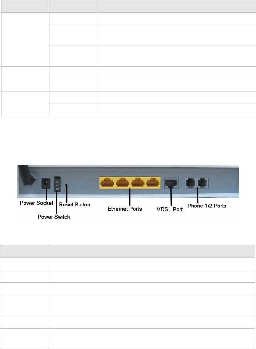
Figure 1-2 Rear panel
Table 1-2 Rear panel items
VDSL Diag On Diagnostics is running.
Flashing The CellPipe 7130 RG failed diagnostic when booting or
resetting.
Off The CellPipe 7130 RG is functional and diagnostics is not
running.
Internet On The CellPipe 7130 RG is connected to the Internet.
Off The CellPipe 7130 RG is not connected to the Internet.
Message Slow flashing Firmware upgrade in progress.
Off No firmware upgrade in progress.
Notes:
* Slow flashing: LED flashes at the rate of 2 seconds on and 2 seconds off.
† Fast flashing: LED flashes at a rate of 0.2 seconds on and 0.2 seconds off.
Item Description
Power socket DC power adapter port.
Power switch Power On/Off switch.
Reset button Press and hold for 5 s to restore the factory default settings.
Ethernet ports
1 to 4
Four RJ-45 ports to connect up to four Ethernet PCs or a Hub.
VDSL port Input port for the VDSL network connection to the ISP.
Phone ports 1
to 2
Two RJ-11 ports for connecting telephones for VoIP.
LED Status Description

2-1
3FE-63398-AAAA-TCZZA
Edition 01 April 2009
............................................................................................................................................................................................................................................................
2 Hardware installation
Overview
Purpose
This chapter provides the instructions to install the CellPipe 7130 RG hardware.
Contents
This chapter covers the following topic:
To install the CellPipe 7130 RG
Supplies
•CellPipe 7130 RG
•RJ-11 telephone cable
•two RJ-45 category 5 Ethernet cable
•power adapter
Before you begin
CAUTION
Potential for equipment damage and personal harm
Before installing the CellPipe 7130 RG, ensure you have thoroughly read the Safety
precautions and Prerequisites in chapter 1.
Turn off all devices (computer, hub, CellPipe 7130 RG) before beginning this procedure.
To install the CellPipe 7130 RG 2-1
............................................................................................................................................................................................................................................................
To install the CellPipe 7130 RGHardware installation
2-2 3FE-63398-AAAA-TCZZA
Edition 01 April 2009
............................................................................................................................................................................................................................................................
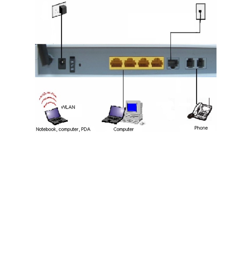
Figure 2-1 Cable connections
Procedure
1. Connect the power adapter jack into the power socket on the CellPipe 7130 RG and
plug the power adapter plug into an outlet.
2. Connect one end of the RJ-45 cable into the VDSL port on the CellPipe 7130 RG and
the other end to your telephone/DSL service connection.
3. If you have VoIP, connect your phone(s) to the phone port(s) on the CellPipe 7130 RG.
4. Connect one end of the RJ-45 Ethernet cable to the Ethernet LAN port (1 to 4) on the
CellPipe 7130 RG and the other end to your Ethernet PC (or LAN hub if you are
setting up an intranet).
5. Turn the power switch on.
........................................................................................................................................................
END OF STEPS
You must also configure the Internet properties on your Ethernet PC; see the TCP/IP
Appendix or Quick Installation Guide for detailed instructions.
After setting up and configuring the CellPipe 7130 RG and your PC(s), you can access the
web configuration tool.

3-1
3FE-63398-AAAA-TCZZA
Edition 01 April 2009
............................................................................................................................................................................................................................................................
3 Accessing the CellPipe
7130 RG web
configuration tool
Overview
Purpose
This chapter explains how to access the CellPipe 7130 RG web configuration tool by
entering the IP address and the default passwords.
The management interface software is HTML-based and can be accessed using a web
browser.
Contents
This chapter covers the following topic:
To access the CellPipe 7130 RG web configuration tool
When to use
Use this procedure to access the web configuration interface of the CellPipe 7130 RG. The
configuration interface enables you to secure the CellPipe 7130 RG, limit access, set
traffic routes, modify passwords, and change advanced settings.
Before you begin
Before you can configure the CellPipe 7130 RG, it must be installed, connected to a web-
enabled PC, and turned on.
Management IP settings
To establish the initial connection, either use a computer configured to be a DHCP client,
or use a computer with IP settings in the 192.168.1.0 subnet. The default IP address of the
CellPipe 7130 RG for the first LAN port is 192.168.1.1 with a subnet 255.255.255.0.
To access the CellPipe 7130 RG web configuration tool 3-1
............................................................................................................................................................................................................................................................
To access the CellPipe 7130 RG web configuration toolAccessing the CellPipe 7130 RG web configuration tool
3-2 3FE-63398-AAAA-TCZZA
Edition 01 April 2009
............................................................................................................................................................................................................................................................
Note: If you are not sure how to configure your computer to be a DHCP client or to
set your IP address and subnet mask, see the TCP/IP Appendix or the Quick
Installation Guide.
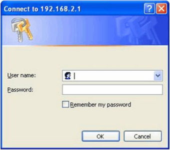
Procedure
1. Open a web browser and enter the IP address of the CellPipe 7130 RG in the address
bar:
http://192.168.2.1 !
The login window appears; see Figure 3-1.
Figure 3-1 Login window
2. Enter your username and password and click OK.
The default admin username is admin and the default admin password is admin.
The Status window appears; see Figure 3-2.
To access the CellPipe 7130 RG web configuration toolAccessing the CellPipe 7130 RG web configuration tool
............................................................................................................................................................................................................................................................
3FE-63398-AAAA-TCZZA
Edition 01 April 2009 3-3
............................................................................................................................................................................................................................................................
Figure 3-2 Status window
The status window is described in Chapter 4, “Status”.
Note: Once you have logged in for the first time, you should change your login
password. See the System Setting section in the Utilities chapter for instructions.
........................................................................................................................................................
END OF STEPS
Configuration menus
All configuration and management of the CellPipe 7130 RG is done using the web
configuration tool. Click on the Status, Network, WiFi Setup, Firewall, Advanced Setup,
QoS and Utilities tabs to view the configuration menus or information located in each
directory.
The menus used to configure basic settings are located in the Status menu of the web page
used for management; for more information, see the Status chapter.
............................................................................................................................................................................................................................................................
To access the CellPipe 7130 RG web configuration toolAccessing the CellPipe 7130 RG web configuration tool
3-4 3FE-63398-AAAA-TCZZA
Edition 01 April 2009
............................................................................................................................................................................................................................................................

4-1
3FE-63398-AAAA-TCZZA
Edition 01 April 2009
............................................................................................................................................................................................................................................................
4 Status
Overview
Purpose
This chapter describes the contents of the Status menu, which contains the status
information for the CellPipe 7130 RG, its connections, and the connected hardware.
Click the Status drop-down menu to open the Status menu.
Contents
This chapter covers the following topics:
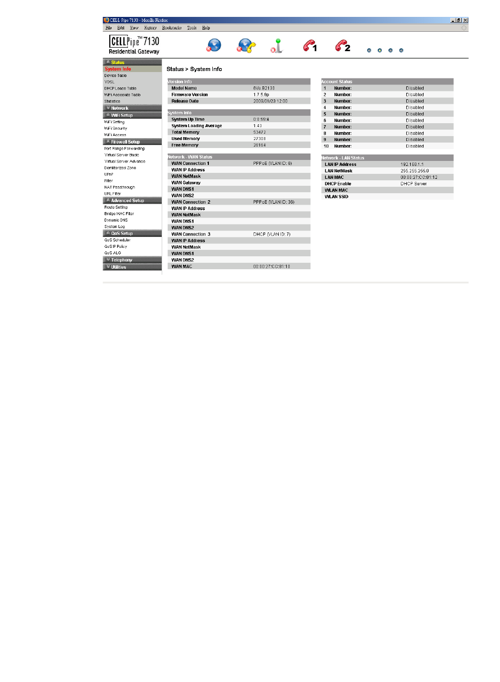
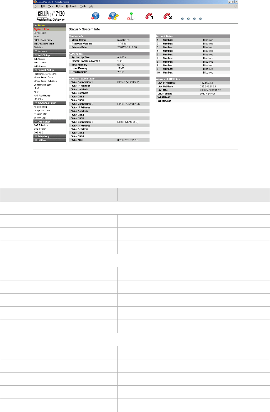
System Info
The System Info window displays the current status of the software, system time, memory,
and WAN connection.
Select System Info in the Status menu to access the System Info window; see Figure 4-1.
The System Info window is the home page of the configuration menus.
System Info 4-1
Device Table 4-3
VDSL 4-4
DHCP Lease Table 4-6
WiFi Associate Table 4-7
Statistics 4-8
............................................................................................................................................................................................................................................................
System InfoStatus
4-2 3FE-63398-AAAA-TCZZA
Edition 01 April 2009
............................................................................................................................................................................................................................................................
Figure 4-1 System Info window
Table 4-1 describes the fields of the System Info window.
Table 4-1 Field descriptions
Field Description
Version Info
Model Name The model name of the modem.
Firmware Version The current version of the firmware.
Release Date The release date of the firmware.
System Info
System Up Time The amount of time the system has been operational.
System Loading Average The average time for the system to load.
Total Memory The memory capacity of the system in kb/s.
Used Memory The memory used in the system.
Free Memory The free memory in the system.
Network - WAN Status
WAN Connection 1 to 3 The WAN connection method.
WAN IP Address The IP address of the WAN interface.
WAN NetMask The subnet mask of the WAN interface.
WAN Gateway The gateway IP address for the WAN interface.
WAN DNS1 The primary DNS for the WAN connection.

Device TableStatus
............................................................................................................................................................................................................................................................
3FE-63398-AAAA-TCZZA
Edition 01 April 2009 4-3
............................................................................................................................................................................................................................................................
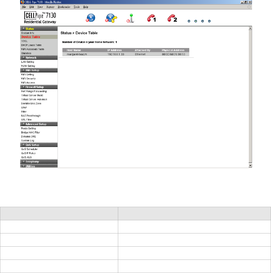
Device Table
The Device Table displays information about the hardware connected to the CellPipe 7130
RG.
Select Device Table in the Status menu to access the Device Table; see Figure 4-2.
WAN DNS2 The secondary DNS for the WAN connection.
WAN MAC The MAC address of the WAN connections.
Account Status
1 to 10 Number: The status (Enabled or Disabled) of accounts 1 to
10.
Network - LAN Status
LAN IP Address The IP address of the LAN interface.
LAN NetMask The subnet mask of the LAN interface.
LAN MAC The MAC address of the LAN interface.
DHCP Enable The status of the LAN DHCP.
WLAN MAC The WLAN MAC address of the WLAN interface.
WLAN SSID The service set identifier used to identify the
particular WLAN connection.
Field Description
............................................................................................................................................................................................................................................................
VDSLStatus
4-4 3FE-63398-AAAA-TCZZA
Edition 01 April 2009
............................................................................................................................................................................................................................................................
Figure 4-2 Device Table
Table 4-2 describes the fields of the Device Table.
Table 4-2 Field descriptions
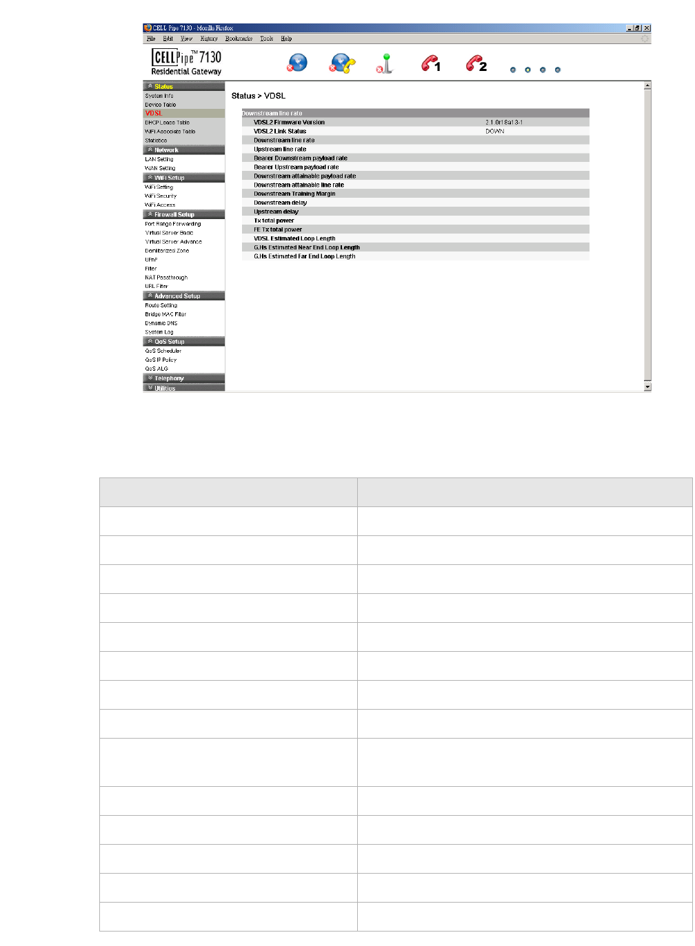
VDSL
The VDSL window displays the VDSL connection status and data.
Select VDSL in the Status menu to access the VDSL window; see Figure 4-3.
Field Description
Host Name The name of the device connected to the gateway.
IP Address The IP address of the client device.
Attached By The type of connection.
Physical Address The MAC address of the client adapter.
VDSLStatus
............................................................................................................................................................................................................................................................
3FE-63398-AAAA-TCZZA
Edition 01 April 2009 4-5
............................................................................................................................................................................................................................................................
Figure 4-3 VDSL window
Table 4-3 describes the fields of the VDSL window.
Table 4-3 Field descriptions
Field Description
VDSL2 Firmware Version The version of firmware in use.
VDSL2 Link Status The status of VDSL2 link.
Downstream line rate The rate of the downstream data transfer in kb/s.
Upstream line rate The rate of the upstream data transfer in kb/s.
Bearer Downstream payload rate The estimated downstream payload rate in kb/s.
Bearer Upload payload rate The estimated upload payload rate in kb/s.
Downstream attainable payload rate The achievable downstream payload rate in kb/s.
Upstream attainable line rate The achievable upstream payload rate in kb/s.
Downstream Training Margin The downstream margin used for training DSL in
dBm.
Downstream delay The downstream delay in s.
Upstream delay The upstream delay in s.
Tx total power Total power used in transmission.
FE Tx total power Total power used in Fast Ethernet 100BASE-TX.
VDSL Estimated Loop Length The estimated VDSL loop length in m.
............................................................................................................................................................................................................................................................
DHCP Lease TableStatus
4-6 3FE-63398-AAAA-TCZZA
Edition 01 April 2009
............................................................................................................................................................................................................................................................
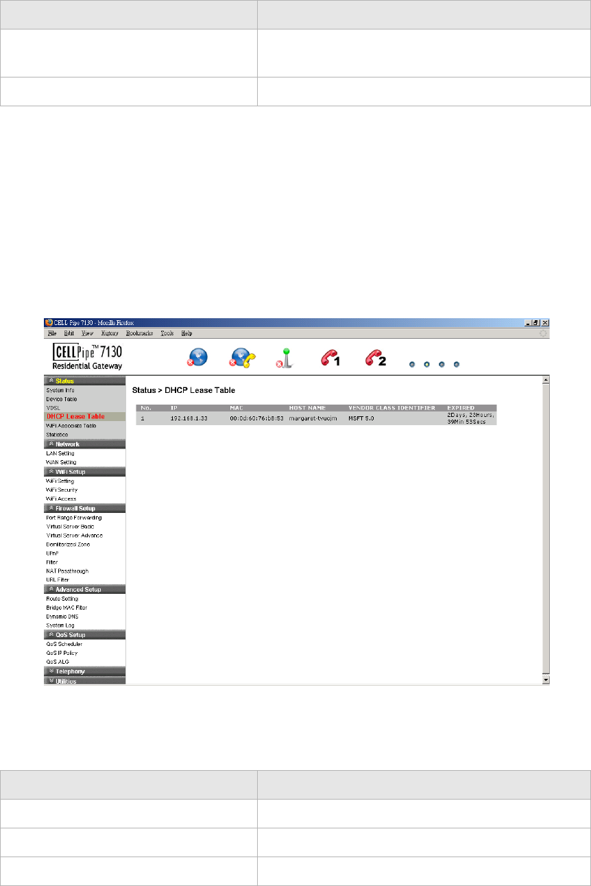
DHCP Lease Table
The DHCP Lease Table displays the DHCP settings.
Select DHCP Lease Table in the Status menu to access the DHCP Lease Table; see
Figure 4-4.
Figure 4-4 DHCP Lease Table
Table 4-4 describes the fields of the DHCP Lease Table.
Table 4-4 Field descriptions
G.Hs Estimated Near End Loop Length The estimated G.handshake (ITU G.994.1) near end
loop length.
G.Hs Estimated Far End Loop Length The estimated G.handshake far end loop length.
Field Description
Field Description
IP Address The IP address of the DHCP client computer.
MAC Address The MAC address of the DHCP client computer.
Host Name The host name of the DHCP client computer.
WiFi Associate TableStatus
............................................................................................................................................................................................................................................................
3FE-63398-AAAA-TCZZA
Edition 01 April 2009 4-7
............................................................................................................................................................................................................................................................
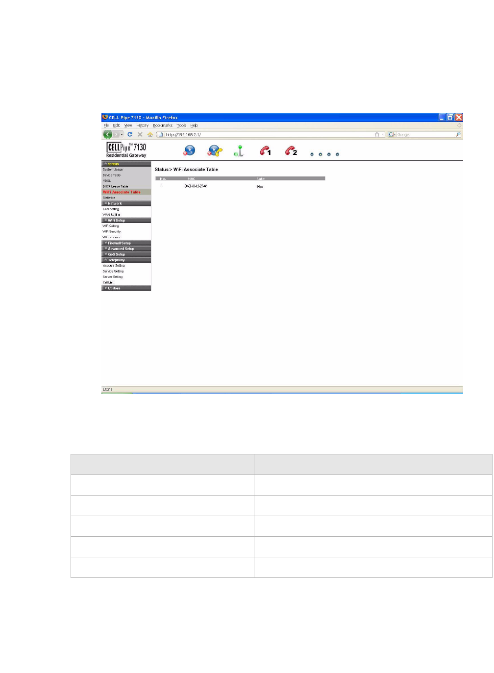
WiFi Associate Table
The WiFi Associate Table displays the connected clients.
Select WiFi Associate Table in the Status menu to access the WiFi Associate Table; see
Figure 4-5.
Figure 4-5 WiFi Associate Table
Table 4-5 describes the fields of the WiFi Associate Table.
Table 4-5 Field descriptions
Field Description
NO. The number index of the client computer.
MAC The MAC address of the client computer.
Rate The connection mode of the wireless network.
Vendor Class Identifier Identifies the client's platform for the DHCP lease.
Expired The period of time that the DHCP lease will expire.
............................................................................................................................................................................................................................................................
StatisticsStatus
4-8 3FE-63398-AAAA-TCZZA
Edition 01 April 2009
............................................................................................................................................................................................................................................................
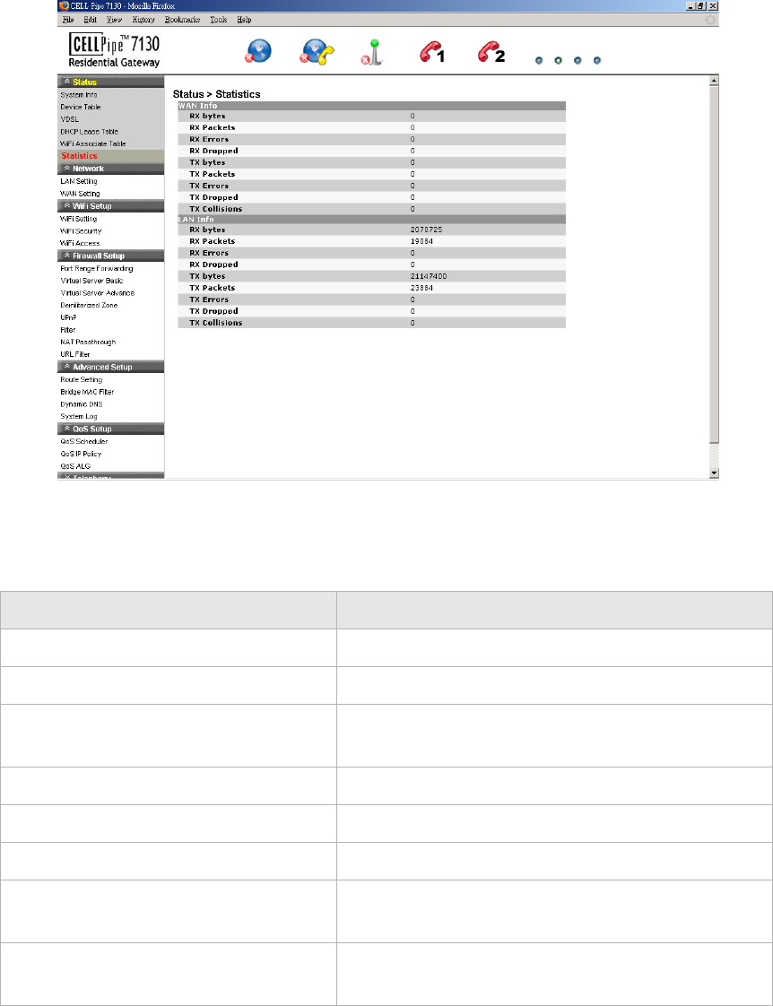
Statistics
The Statistics window displays the number of bytes that have been received and
transmitted by the LAN and WAN interfaces.
Select Statistics in the Status menu to access the Statistics window; see Figure 4-6.
Figure 4-6 Statistics window
Table 4-6 describes the WAN and LAN fields of the Statistics window.
Table 4-6 Field descriptions
Field Description
RX bytes The number of bytes that have been received.
RX Packets The number of packets that have been received.
RX Errors The number of packets that have been received with
errors.
RX Dropped The number of packets dropped after being received.
TX bytes The number of bytes that have been transmitted.
TX Packets The number of packets that have been transmitted.
TX Errors The number of packets that have been transmitted
with errors.
TX Dropped The number of packets dropped after being
transmitted.

StatisticsStatus
............................................................................................................................................................................................................................................................
3FE-63398-AAAA-TCZZA
Edition 01 April 2009 4-9
............................................................................................................................................................................................................................................................
TX Collisions The number of packets collided when transmitted.
Field Description
............................................................................................................................................................................................................................................................
StatisticsStatus
4-10 3FE-63398-AAAA-TCZZA
Edition 01 April 2009
............................................................................................................................................................................................................................................................

5-1
3FE-63398-AAAA-TCZZA
Edition 01 April 2009
............................................................................................................................................................................................................................................................
5Network
Overview
Purpose
This chapter explains how to configure the network settings for the CellPipe 7130 RG
from the Network menu.
Click the Network drop-down menu to open the Network menu.
Contents
This chapter covers the following topics:
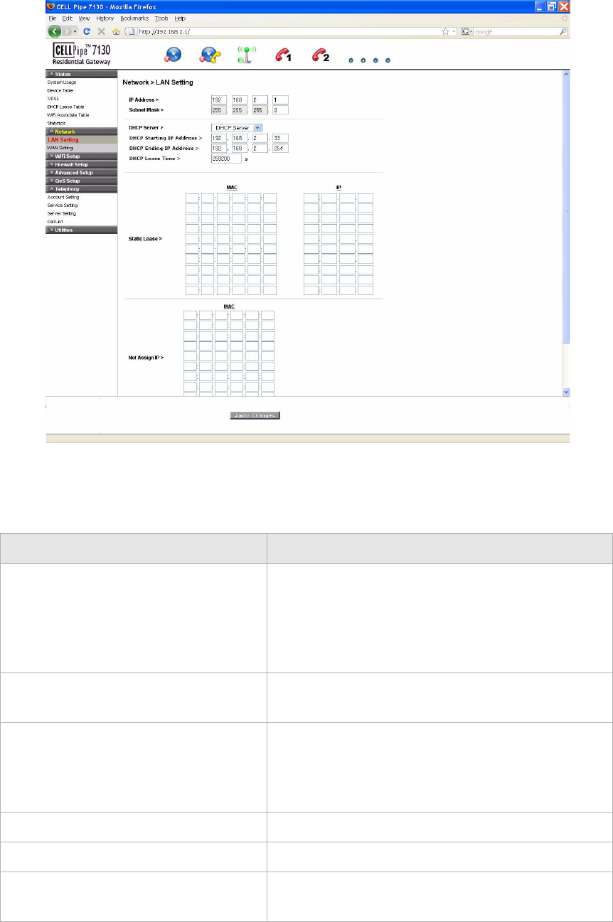
LAN Setting
The LAN Settings include the IP address, subnet mask, DHCP settings, DHCP relay, and
static IP lease.
Select LAN Setting in the Network menu to access the LAN Setting window; see
Figure 5-1.
LAN Setting 5-1
WAN Setting 5-3
............................................................................................................................................................................................................................................................
LAN SettingNetwork
5-2 3FE-63398-AAAA-TCZZA
Edition 01 April 2009
............................................................................................................................................................................................................................................................
Figure 5-1 LAN Setting window
Table 5-1 describes the fields of the LAN Setting window.
Table 5-1 Field descriptions
Field Description
IP Address The IP address of the LAN interface in dotted
decimal notation. The default is 192.168.1.1. You
can change this address as needed to an address that
is reserved for private use. The range of private
addresses is 192.168.1.1 to 192.168.255.254.
Subnet Mask The subnet mask of the IP addresses in your LAN;
for example, 255.255.255.0.
DHCP Server If enabled, the CellPipe 7130 RG assigns IP
addresses, an IP default gateway, and DNS servers to
computers that support the DHCP client; for
example, Windows 95, Windows NT.
DHCP Starting IP Address The first value of contiguous IP addresses.
DHCP Ending IP Address The last value of contiguous IP addresses.
DHCP Lease Time The time period during which the computers retain
the IP addresses assigned to them.

WAN SettingNetwork
............................................................................................................................................................................................................................................................
3FE-63398-AAAA-TCZZA
Edition 01 April 2009 5-3
............................................................................................................................................................................................................................................................
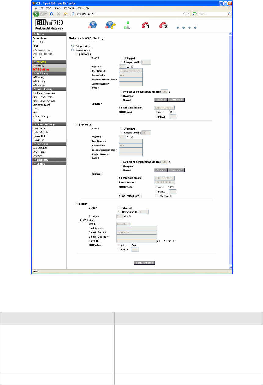
WAN Setting
The WAN settings include the configuration for both the Bridge Mode and Routed Mode.
Select WAN Setting in the Network menu to access the WAN setting window. You can
configure the WAN in Bridged Mode (see Figure 5-2) or Routed Mode (see Figure 5-3).
Bridged Mode
When bridge mode is selected, the basic functions of the router, such as the firewall, route
setting, DHCP server, DDNS, QoS, and UPnP, are disabled.
Select the Bridged Mode option from the WAN>Hybrid setting window to enable the
Bridged Mode WAN setting; see Figure 5-2.
Static Lease The set MAC associations and IP addresses. Assign
the static IP lease to the designated client's adaptor.
Not Assign IP The client's MAC address to be filtered from the
DHCP lease.
Apply Changes Click to save your changes.
Field Description
............................................................................................................................................................................................................................................................
WAN Settin gNetwork
5-4 3FE-63398-AAAA-TCZZA
Edition 01 April 2009
............................................................................................................................................................................................................................................................
Figure 5-2 Bridged mode WAN settings window
Table 5-2 describes the fields of the Bridged Mode WAN setting window.
Table 5-2 Field descriptions
Field Description
Bridged Mode When the bridged mode radio button is selected, the
CellPipe 7130 RG only uses MAC addresses. The
basic functions of the router such as the Firewall,
Route, DHCP Server, DDNS, and UPnP will be
disabled.
Apply Changes Click to save your changes.
WAN SettingNetwork
............................................................................................................................................................................................................................................................
3FE-63398-AAAA-TCZZA
Edition 01 April 2009 5-5
............................................................................................................................................................................................................................................................
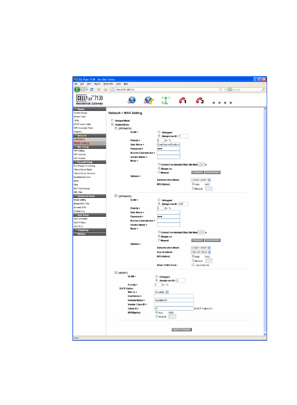
Routed Mode
If the Routed Mode option is selected the CellPipe 7130 RG uses IP addresses and subnet
masks. The functions of the router such as the Firewall, Route, DHCP Server, DDNS, and
UPnP can be enabled.
Select the Routed Mode option from the WAN>Hybrid setting window to enable the routed
mode WAN setting; see Figure 5-3.
Figure 5-3 Routed Mode WAN setting window
Table 5-3 describes the fields of the Routed Mode WAN setting window.

............................................................................................................................................................................................................................................................
WAN Settin gNetwork
5-6 3FE-63398-AAAA-TCZZA
Edition 01 April 2009
............................................................................................................................................................................................................................................................
Table 5-3 Field descriptions
Fields Description
[PPPoE#1] to [PPPoE#2] Enable one or both of the supported VLAN over
PPPoE.
VLAN
Untagged Enable if a VLAN ID is not being used.
Always Use ID Enable if a VLAN ID is being used and enter the ID
number (between 2 to 4094).
Priority Enter a priority level from 0 to 7 to define user
priority.
User Name Enter the user name for the PPPoE connection.
Password Enter the password for the PPPoE connection.
Access Concentrator The access concentrator is optional. Consult with
your ISP for information.
Service Name The service name is optional. Consult with your ISP
for information.
Mode
Connect on demand: Max idle time Select to have the router connect to the Internet only
when you choose to do so. Enter a max idle time to
specify the maximum number of idle seconds after
which the connection is dropped.
Always on Select to always have the router connect to the
Internet.
Manual Select and then click Connect to manually connect
the router to the internet. Click Disconnect to end
the connection.
Options
Authentication Mode Select the authentication mode from the drop-down
menu. Options include:
•CHAP + PAP
•CHAP
•PAP
This is optional. Your ISP will provide this
information if it is necessary.
MTU (bytes) Enable Auto to set the maximum transfer unit to
the default (1492), or enable Manual to manually
enter a unit.
Apply Changes Click to save your changes.

6-1
3FE-63398-AAAA-TCZZA
Edition 01 April 2009
............................................................................................................................................................................................................................................................
6 WiFi Setup
Overview
Purpose
This chapter explains how to configure the WiFi settings for the CellPipe 7130 RG from
the WiFi setup menu.
Click the WiFi Setup drop-down menu to open the WiFi Setup menu.
Contents
This chapter covers the following topics:
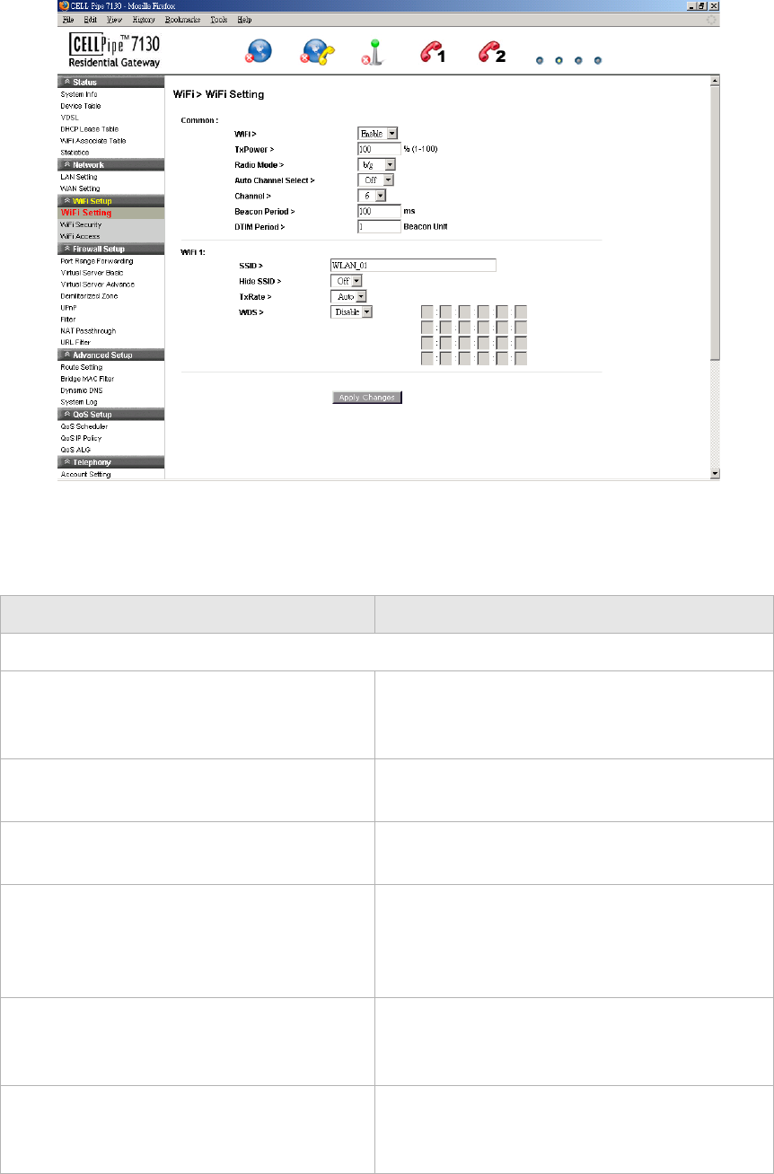
WiFi Setting
The WiFi Setting window enables you to configure the common wireless and WiFi 1
settings.
Click on WiFi Setting in the WiFi Setup menu to access the WiFi Setting window; see
Figure 6-1.
WiFi Setting 6-1
WiFi Security 6-3
WiFi Access 6-5
............................................................................................................................................................................................................................................................
WiFi SettingWiFi Setup
6-2 3FE-63398-AAAA-TCZZA
Edition 01 April 2009
............................................................................................................................................................................................................................................................
Figure 6-1 WiFi Setting window
Table 6-1 describes the fields of the WiFi Setting window.
Table 6-1 Field descriptions
Field Description
Common
WiFi To configure the wireless LAN settings, click
the drop-down menu and select Enable. Select
Disable to end the wireless LAN.
TxPower Enter a percentage to set the parameter of your
transmission power consumption.
Radio Mode Click the drop-down menu and select either
b/g, b, or g for the wireless mode.
Auto Channel Select Click the drop-down menu and select On to
have the wireless access point automatically
select the channel with the least interference.
Select Off to configure manually.
Channel If the auto channel select is off, you can
manually select the wireless access point. The
default is 6.
Beacon Period Enter a beacon period in ms to determine the
frequency of the beacon to keep the network
synchronized. This is optional.

WiFi SecurityWiFi Setup
............................................................................................................................................................................................................................................................
3FE-63398-AAAA-TCZZA
Edition 01 April 2009 6-3
............................................................................................................................................................................................................................................................
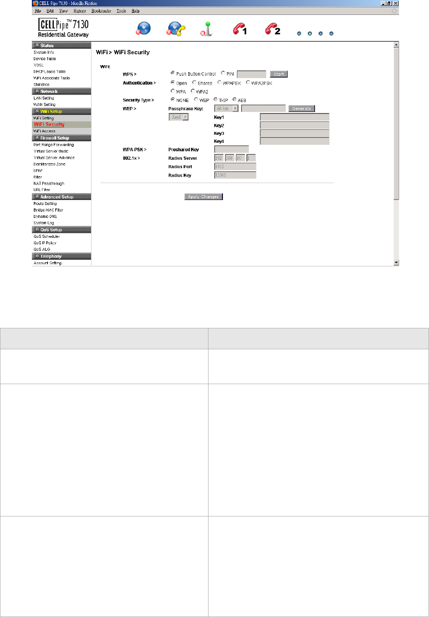
WiFi Security
WiFi security enables you to configure the WEP, WPA, or WPA2 security settings.
Select WiFi Security in the WiFi Setup menu to access the WiFi security window; see
Figure 6-2.
DTIM Period Enter a value to set the delivery traffic
indication message. The DTIM field is a
countdown field informing clients of the next
window for listening to broadcast and multicast
messages.
WiFi 1
SSID Enter an SSID name (max. 32 characters). The
SSID is an alphanumeric name shared by
devices on the wireless network.
Hide SSID Click the drop-down menu and selct On to hide
the SSID or Off to allow others to see your
SSID.
TxRate Click the drop-down menu and select Auto to
automatically determine the transmission rate
or select a transmission rate (max. 54Mbps).
WDS1Click the drop-down menu and select Enable if
you would like to enter the wireless MAC of
other wireless access points or routers that are
in the same WDS.
Apply Changes Click to save your changes.
Notes:
1 If you enable WDS, check that all other WDS APs are enabled, configured with the same
channel, SSID, and encryption keys, and that each AP has a different LAN port IP
address.
Field Description
............................................................................................................................................................................................................................................................
WiFi SecurityWiFi Setup
6-4 3FE-63398-AAAA-TCZZA
Edition 01 April 2009
............................................................................................................................................................................................................................................................
Figure 6-2 WiFi Security window
Table 6-2 describes the fields of the WiFi Security settings window.
Table 6-2 Field descriptions
Field Description
WPS Enable Push Button Control or enable PIN
and enter your PIN number and click Start.
Authentication Select one of the following encryption methods
for the wireless network:
•Open
•Shared
•WPAPSK
•WPA2PSK
•WPA
•WPA2
Security Type Select one of the following for the security
type:
•NONE
•WEP
•TKIP
•AES

WiFi AccessWiFi Setup
............................................................................................................................................................................................................................................................
3FE-63398-AAAA-TCZZA
Edition 01 April 2009 6-5
............................................................................................................................................................................................................................................................
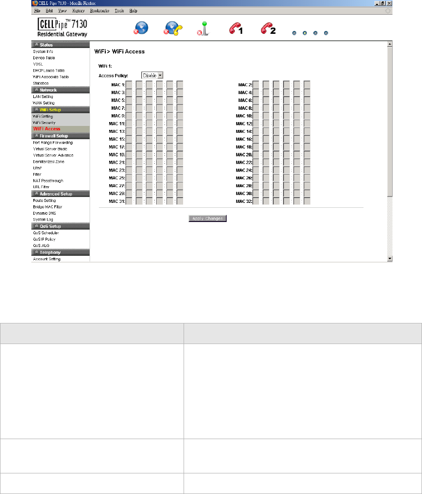
WiFi Access
The WiFi Access window enables you to configure restrictions on some of the clients
associated with the gateway.
Select WiFi Access in the WiFi Setup menu to access the WiFi Access window; see
Figure 6-3 below.
WEP
Passphrase Key Select a level of encryption (64 bits or 128
bits). Enter a passphrase key consisting of 8 to
63 alphanumeric characters and click
Generate.
Key 1 to 4 Select either Key1, Key2, Key3, Key4. Enter
a WEP key in the respective field. The WEP
key must:
•contain letters from A to F and numbers
from 1 to 9
•contain 10 characters for 64 bit and 26
characters for 128 bit encryption
WPA-PSK
Preshared Key Enter a preshared key consisting of 8 to 63
alphanumeric characters.
802.1x
Radius Server Enter the IP address of the RADIUS server.
Radius Port Enter the port number of the RADIUS server.
Radius Key Enter the key of the RADIUS server.
Apply Changes Click to save your changes.
Field Description
............................................................................................................................................................................................................................................................
WiFi AccessWiFi Setup
6-6 3FE-63398-AAAA-TCZZA
Edition 01 April 2009
............................................................................................................................................................................................................................................................
Figure 6-3 WiFi Access window
Table 6-3 describes the fields of the WiFi Access window.
Table 6-3 Field descriptions
Field Description
Access Policy Select one of the following:
•Disable to turn off WiFi filtering
•Allow to permit access from the specified MAC
address.
•Deny to deny access from the specified MAC
address.
MAC 1 to 32 Enter up to 32 MAC addresses to control access for
these addresses.
Apply Changes Click to save your changes.