GemTek Technology P980430N 7130 Residential Gateway 6Ve.A2130 User Manual 6Ve A2130 UM
Gemtek Technology Co., Ltd. 7130 Residential Gateway 6Ve.A2130 6Ve A2130 UM
Contents
- 1. Manual 1
- 2. Manual 2
Manual 2

7-1
3FE-63398-AAAA-TCZZA
Edition 01 April 2009
............................................................................................................................................................................................................................................................
7Firewall Setup
Overview
Purpose
This chapter explains how to configure the firewall for the CellPipe 7130 RG.
Click the Firewall drop-down menu to open the Firewall Setup menu.
Contents
This chapter covers the following topics:
Port Range Forwarding
The Port Range Forwarding window enables you to control the traffic passing through the
ports.
Note: It is recommended that port range forwarding be configured with the
assistance of your ISP.
Select Port Range Forwarding in the Firewall Setup menu to access the Port Range
Forwarding window; see Figure 7-1.
Port Range Forwarding 7-1
Virtual Server Basic 7-3
Virtual Server Advance 7-4
Demilitarized Zone 7-6
UPnP 7-7
Filter 7-8
NAT Passthrough 7-10
URL Filter 7-11
............................................................................................................................................................................................................................................................
Port Range ForwardingFirewall Setup
7-2 3FE-63398-AAAA-TCZZA
Edition 01 April 2009
............................................................................................................................................................................................................................................................
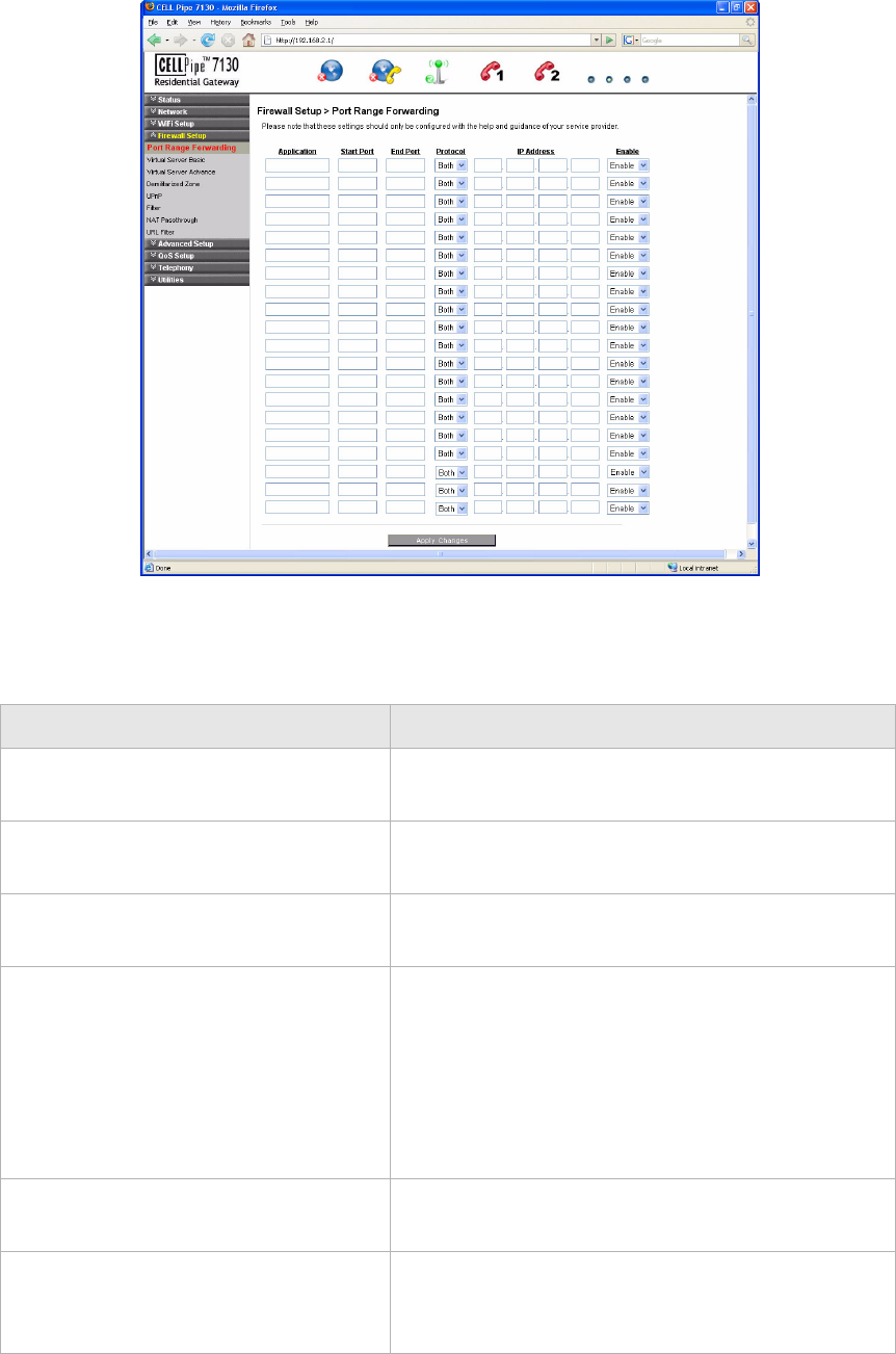
Figure 7-1 Port Range Forwarding window
Table 7-1 describes the fields of the Port Range Forwarding window.
Table 7-1 Field descriptions
Field Description
Application Enter the name of an application you are hosting on
your LAN PC; for example, Real Audio.
Start Port Enter the starting number of the port range used for
the application.
End Port Enter the ending number of the port range used for
the application.
Protocol Select one of:
•TCP
•UDP
•Both
The type of application determines what protocol is
required.
IP Address Enter the IP address of the LAN PC that is running
the application.
Enable Select Enable to allow port forwarding for the
application. Select Disable to stop port forwarding
for the application.
Virtual Server BasicFirewall Setup
............................................................................................................................................................................................................................................................
3FE-63398-AAAA-TCZZA
Edition 01 April 2009 7-3
............................................................................................................................................................................................................................................................
Virtual Server Basic
The virtual server acts as a gateway to pass your service request from the Internet client to
your LAN servers.
Select Virtual Server Basic in the Firewall Setup menu to access the Virtual Server Basic
window; see Figure 7-2.
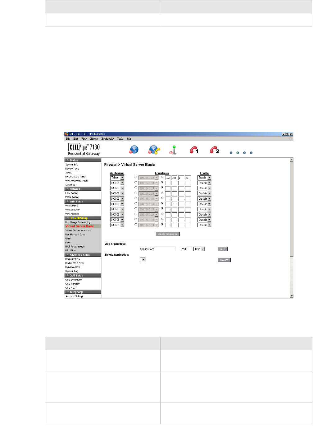
Figure 7-2 Virtual Server Basic window
Table 7-2 describes the fields of the Virtual Server Basic window.
Table 7-2 Field descriptions
Apply Changes Click to save your changes.
Field Description
Field Description
Application Select the application to be served by the virtual
server.
IP Address Select the radio button in the left column to select a
pre-configured LAN host or select the radio button in
the right column and enter an IP address manually.
Enable Select Enable to connect the virtual server. Select
Disable to end the connection.

............................................................................................................................................................................................................................................................
Virtual Server AdvanceFirewall Setup
7-4 3FE-63398-AAAA-TCZZA
Edition 01 April 2009
............................................................................................................................................................................................................................................................
Virtual Server Advance
Advanced settings enable you to use a different port other than the standard port for your
service/server. The router conducts the port-level translation.
Select Virtual Server Advance in the Firewall Setup menu to access the Virtual Server
Advance window; see Figure 7-3.
Apply Changes Click to save your changes.
Add Application
Application Enter the name of an application you are hosting on
your LAN PC.
Port Enter the desired port in the Port field and then
select the required protocol.
Add Click to add the application to the virtual server.
Your added application is now available in the
application list for configuration.
Delete Application Click the drop-down menu and select the application
to delete.
Delete Click to remove the application from the application
list.
Field Description
Virtual Server AdvanceFirewall Setup
............................................................................................................................................................................................................................................................
3FE-63398-AAAA-TCZZA
Edition 01 April 2009 7-5
............................................................................................................................................................................................................................................................
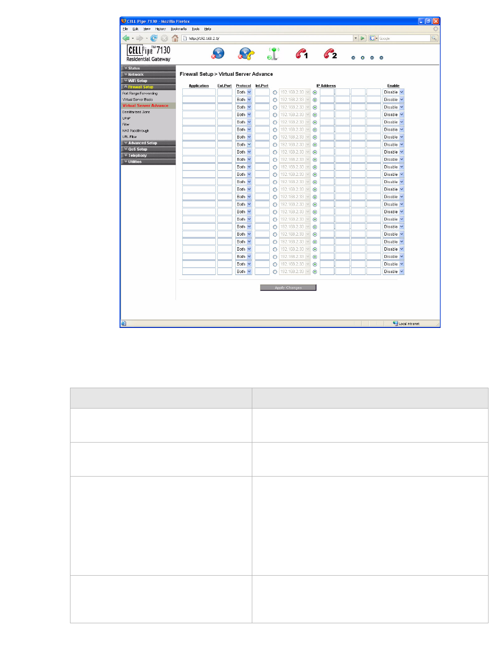
Figure 7-3 Virtual Server Advance window
Table 7-3 describes the fields of the Virtual Server Advance window.
Table 7-3 Field descriptions
Field Description
Application Enter the name of an application to be hosted on the
virtual server.
Ext.Port Enter the external port that will be forwarded for the
WAN traffic.
Protocol Select one of the following:
•TCP
•UDP
•Both
The type of application determines what protocol is
required.
Int.Port Enter the number of the internal port for the
application. The internal port is the port used by
your LAN server.
............................................................................................................................................................................................................................................................
Demilitarized ZoneFirewall Setup
7-6 3FE-63398-AAAA-TCZZA
Edition 01 April 2009
............................................................................................................................................................................................................................................................
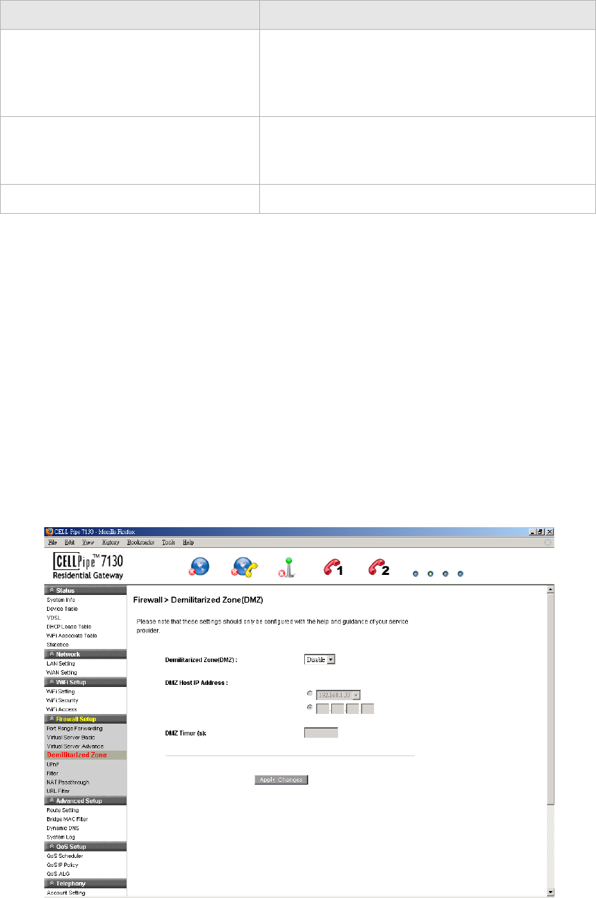
Demilitarized Zone
The Demilitarized Zone window enables you to configure a single computer to be exposed
to an unrestricted two-way communication from outside of your network; see Table 7-4.
Note: Use the demilitarized zone setting only if the virtual server or port range
forwarding options do not provide the level of access required for certain applications.
It is recommended that you contact your ISP for assistance.
Select Demilitarized Zone in the Firewall Setup menu to access the demilitarized zone
window; see Figure 7-4.
Figure 7-4 Demilitarized Zone window
Table 7-4 describes the fields of the Demilitarized Zone window.
IP Address Enable the radio button in the left column to select a
pre-configured LAN host or enable the radio button
in the right column and enter an IP address
manually.
Enable Select Enable to apply this virtual server
configuration rule or Disable to turn off this virtual
server configuration rule.
Apply Changes Click to save your changes.
Field Description
UPnPFirewall Setup
............................................................................................................................................................................................................................................................
3FE-63398-AAAA-TCZZA
Edition 01 April 2009 7-7
............................................................................................................................................................................................................................................................
Table 7-4 Field descriptions
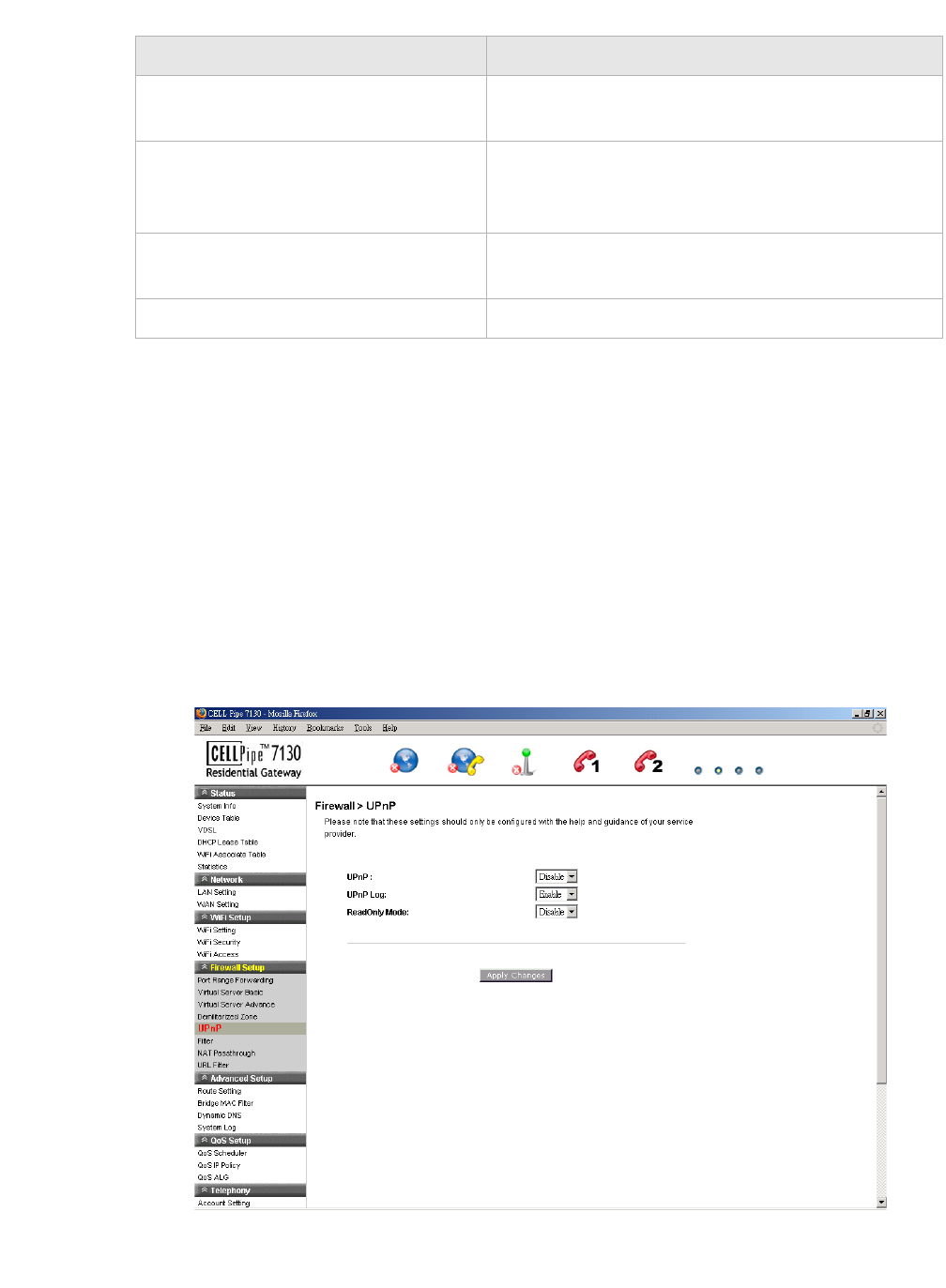
UPnP
UPnP is an open networking standard that allows peer-to-peer network connectivity
between devices. It enables software or devices, such as video game consoles, to function
properly using NAT. See Table 7-5 below.
Note: It is recommended that you contact your ISP for assistance.
Select UPnP in the Firewall Setup menu to access the UPnP window; see Figure 7-5.
Figure 7-5 UPnP window
Table 7-5 describes the fields of the UPnP window.
Field Description
Demilitarized Zone (DMZ) Select Enable to turn on the demilitarized zone
function. Select Disable to turn it off.
DMZ Host IP Address Select the first radio button and choose a pre-
existing (or preset) LAN host or select the second
radio button and enter an IP address manually.
DMZ Timer To improve security, specify the length of time (in
seconds) during which the DMZ is active.
Apply Changes Click to save your changes.

............................................................................................................................................................................................................................................................
FilterFirewall Setup
7-8 3FE-63398-AAAA-TCZZA
Edition 01 April 2009
............................................................................................................................................................................................................................................................
Table 7-5 Field descriptions
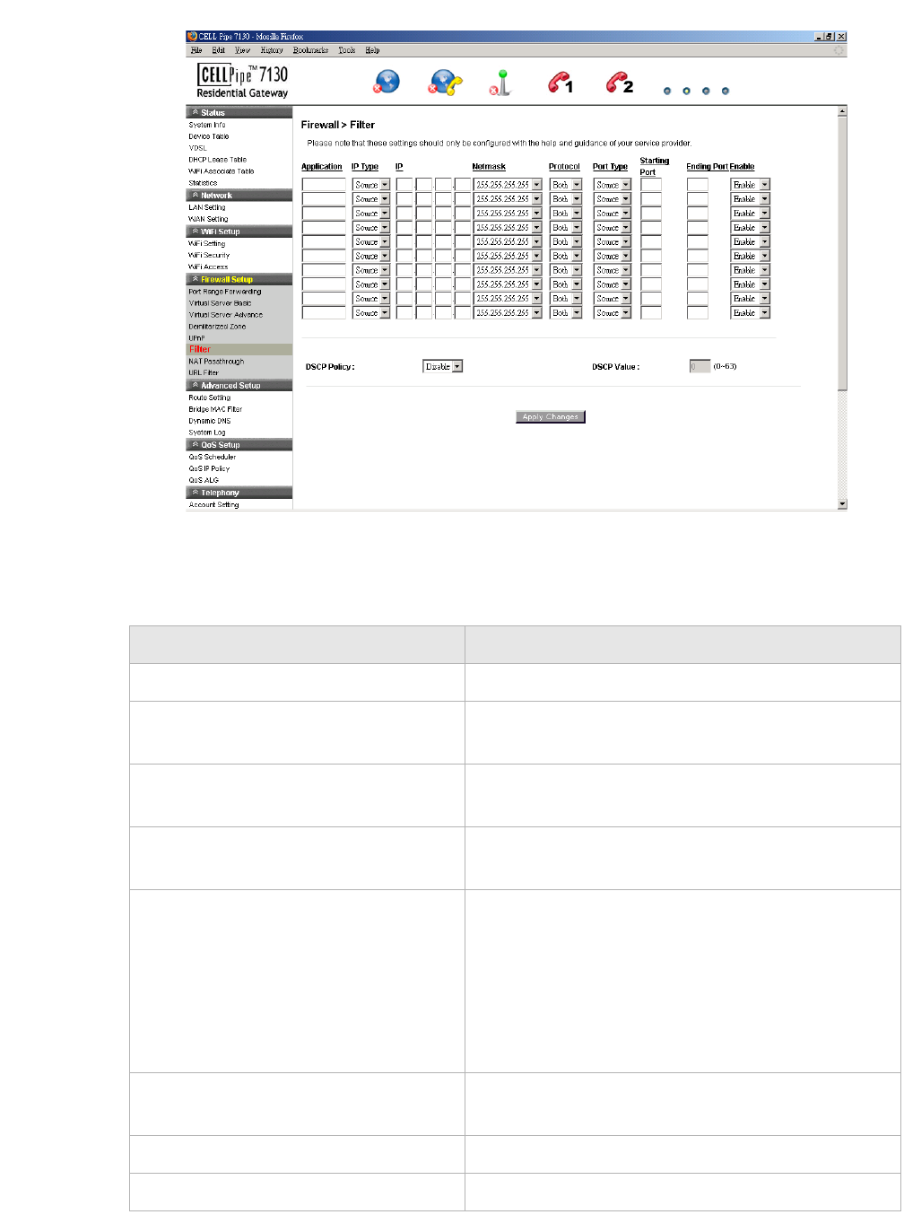
Filter
The filter enables you to disable applications and their associated service ports for specific
clients.
Note: It is recommended that you contact your ISP for assistance configuring the
filter.
Select Filter in the Firewall Setup menu to access the Filter window; see Figure 7-6.
Field Description
UPnP Select Enable to connect the UPnP function. Select
Disable to disconnect the UPnP function.
UPnP Log Select Enable to enable the logging activities.
Select Disable to disable the logging activities.
ReadOnly Mode Select Enable to turn on the read-only mode. Select
Disable to turn off the read-only mode.
Note: In read-only mode, users are unable to
change port forwarding settings or any other UPnP
enabled application settings.
Apply Changes Click to save your changes.
FilterFirewall Setup
............................................................................................................................................................................................................................................................
3FE-63398-AAAA-TCZZA
Edition 01 April 2009 7-9
............................................................................................................................................................................................................................................................
Figure 7-6 Filter window
Table 7-6 describes the fields of the Filter window.
Table 7-6 Field descriptions
Field Description
Application Enter the name of the application to be filtered.
IP Type Select Dest (destination) or Source depending on
the how the rule has been defined.
IP Enter the IP address of the host you are blocking
from the application.
Netmask Select the Netmask of the host you are blocking
from the application.
Protocol Select one of the following:
•TCP
•UDP
•Both
The type of application determines what protocol is
required.
Port Type Select Dest (destination) or Source depending on
the type of application.
Starting Port Enter the starting port number of the application.
Ending Port Enter the ending port number of the application.
............................................................................................................................................................................................................................................................
NAT PassthroughFirewall Setup
7-10 3FE-63398-AAAA-TCZZA
Edition 01 April 2009
............................................................................................................................................................................................................................................................
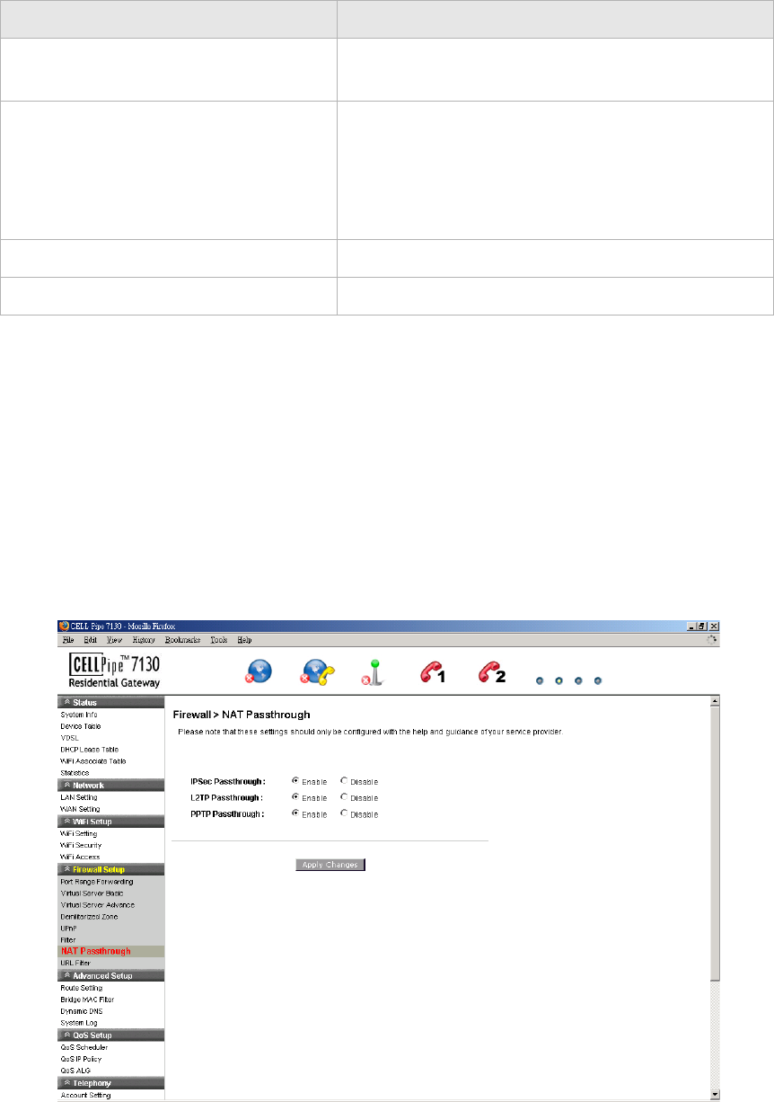
NAT Passthrough
The NAT Passthrough window allows you to enable and disable specific protocols from
passing through the gateway.
Select NAT Passthrough in the Firewall Setup menu to access the NAT Passthrough
window; see Figure 7-7.
Figure 7-7 NAT Passthrough window
Table 7-7 describes the fields of the NAT Passthrough window.
Enable Select Enable to apply this filter configuration rule
or Disable to turn off this filter configuration rule.
DSCP Policy Select Disable to disable the DSCP policy. Select
Deny to deny packets with the specified IP header
DSCP value to access the internet or select Allow to
allow packets with the specified IP header DSCP
value to access the internet.
DSCP Value Enter your DSCP value between 0 to 63.
Apply Changes Click to save your changes.
Field Description
URL FilterFirewall Setup
............................................................................................................................................................................................................................................................
3FE-63398-AAAA-TCZZA
Edition 01 April 2009 7-11
............................................................................................................................................................................................................................................................
Table 7-7 Field descriptions
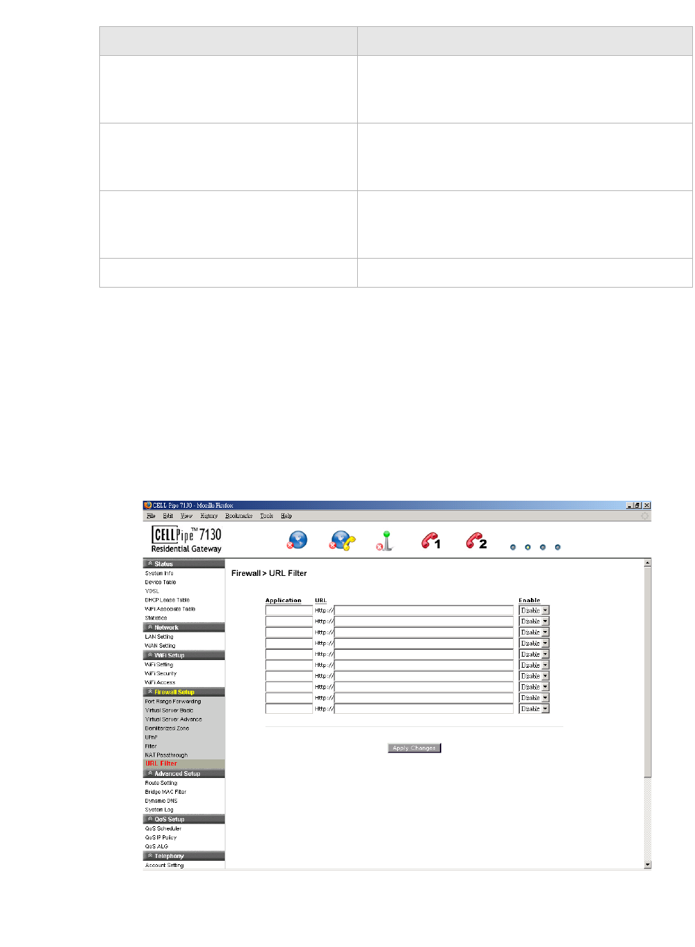
URL Filter
The URL Filter window enables you to block access to specific websites.
Select URL Filter in the Firewall Setup menu to access the URL Filter window; see
Figure 7-8.
Figure 7-8 URL Filter window
Table 7-8 describes the fields for the URL Filter window.
Field Description
IPSec Passthrough Select the Enable radio button to allow IPSec
passthrough. Select Disable to not allow the IPSec
passthrough.
L2TP Passthrough Select the Enable radio button to allow L2TP
passthrough. Select Disable to not allow L2TP
passthrough.
PPTP Passthrough Select the Enable radio button to allow PPTP
passthrough. Select Disable to not allow PPTP
passthrough.
Apply Changes Click to save your changes.

............................................................................................................................................................................................................................................................
URL FilterFirewall Setup
7-12 3FE-63398-AAAA-TCZZA
Edition 01 April 2009
............................................................................................................................................................................................................................................................
Table 7-8 Field descriptions
Field Description
Application Enter a name for the URL filter.
URL Enter a URL or keyword of the URL you are
blocking. If the keyword is too general, you might
inadvertently block other websites. You can enter
multiple URLs and keywords.
Enable Select Enable to apply the URL filter. Select
Disable to turn off the URL filter.
Apply Changes Click to save your changes.

8-1
3FE-63398-AAAA-TCZZA
Edition 01 April 2009
............................................................................................................................................................................................................................................................
8 Advanced Setup
Overview
This chapter explains how to configure the advanced settings of the CellPipe 7130 RG
such as the route setting, bridge MAC filter, dynamic DNS, and system log.
Click the Advanced Setup drop-down menu to open the Advanced Setup menu.
Contents
This chapter covers the following topics:
Route Setting
The Route Setting window enables you to configure static and dynamic routes for routing
packets from one network to another network.
Select Route Setting in the Advanced Setup menu to access the Route Setting window;
see Figure 8-1.
Route Setting 8-1
Bridge MAC Filter 8-3
Dynamic DNS 8-4
System Log 8-5
............................................................................................................................................................................................................................................................
Route SettingAdvanced Setup
8-2 3FE-63398-AAAA-TCZZA
Edition 01 April 2009
............................................................................................................................................................................................................................................................
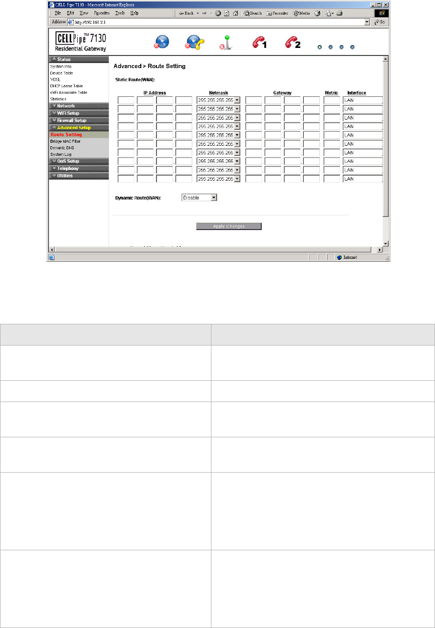
Figure 8-1 Route Setting window
Table 8-1 describes the fields of the Route Setting window.
Table 8-1 Field descriptions
Field Description
Static Route (WAN) Static routing enables you to choose a fixed
path to another network.
IP Address Enter the IP address of the destination network.
Netmask Select and the subnet mask of the destination
network.
Gateway Enter the IP address of the gateway for the
destination network.
Metric In order to determine the best route, a value is
used to specify the cost of the route (the metric
value). Enter the metric value in the metric
field. IP routing uses hop count as measurement
of the metric.
Interface Select the LAN or WAN interface. The packets
sent to the addresses of the destination IP
address are reached through the interface,
however, for the WAN interface it depends on
the WAN configuration.
Bridge MAC FilterAdvanced Setup
............................................................................................................................................................................................................................................................
3FE-63398-AAAA-TCZZA
Edition 01 April 2009 8-3
............................................................................................................................................................................................................................................................
Bridge MAC Filter
The Bridge MAC Filter enables you to control access to and from specific MAC
addresses.
Select Bridge MAC filter in the Advanced Setup menu to access the bridge MAC filter
window; see Figure 8-2.
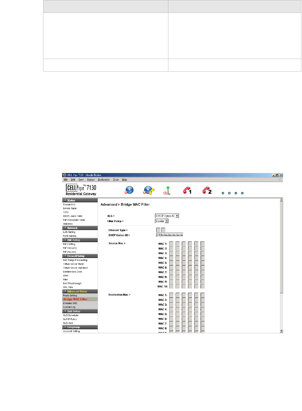
Figure 8-2 Bridge MAC Filter window
Table 8-2 describes the fields of the Bridge MAC Filter window.
Dynamic Route (WAN) Select Enable to use dynamic routing instead
of static. Dynamic routing enables the router to
adapt to changes in the path to the other
network. Select Disable to turn off dynamic
routing.
Apply Changes Click to save your changes.
Field Description

............................................................................................................................................................................................................................................................
Dynamic DNSAdvanced Setup
8-4 3FE-63398-AAAA-TCZZA
Edition 01 April 2009
............................................................................................................................................................................................................................................................
Table 8-2 Field descriptions
Dynamic DNS
The Dynamic DNS (DDNS) window enables you to configure your registered domain
name with a dynamic IP address.
Note: Before you can use this feature, you need to sign up for DDNS service at one
of two DDNS service providers; see DynDNS.org or ChangeIP.com.
Click on Dynamic DNS in the Advanced Setup menu to access the dynamic DNS window;
see Figure 8-3.
Field Description
ALG Select the filtering algorithm:
•Source MAC
•Destination MAC
•DHCP Option 60
•Ethernet Type
Filter Policy Select the filter:
•Allow
•Deny
•Disable
Ethernet Type If you selected Ethernet Type as the filtering
algorithm, enter the applicable Ethernet Type code.
DHCP Option 60 If you selected DHCP Option 60 as the filtering
algorithm, enter the alphanumeric identification.
Source MAC (MAC 1 to 10) Enter the source MAC address of the filter.
Destination MAC (MAC 1 to 10) Enter the destination MAC address of the filter.
Apply Changes Click to save your changes.
System LogAdvanced Setup
............................................................................................................................................................................................................................................................
3FE-63398-AAAA-TCZZA
Edition 01 April 2009 8-5
............................................................................................................................................................................................................................................................
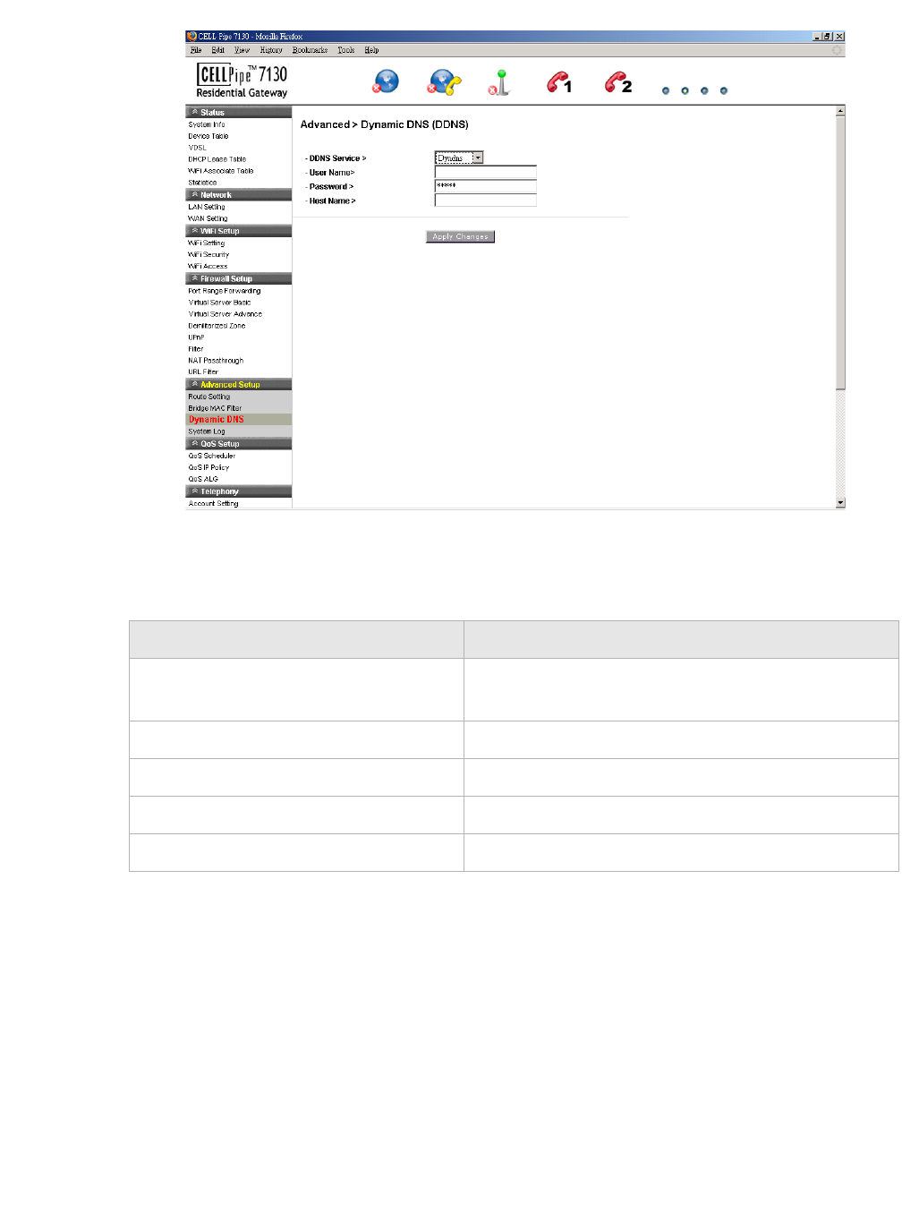
Figure 8-3 Dynamic DNS window
Table 8-3 describes the fields of the Dynamic DNS window.
Table 8-3 Field descriptions
System Log
The System Log window enables you to view the system logs and to send them to a
remote system log server.
Click on System Log in the Advanced Setup menu to access the system log window; see
Figure 8-4.
Field Description
DDNS Service If you have enabled your DDNS, select your DDNS
service.
User Name Enter the username for your DDNS account.
Password Enter the password for your DDNS account.
Host Name Enter the host name.
Apply Changes Click to save your changes.
............................................................................................................................................................................................................................................................
System LogAdvanced Setup
8-6 3FE-63398-AAAA-TCZZA
Edition 01 April 2009
............................................................................................................................................................................................................................................................
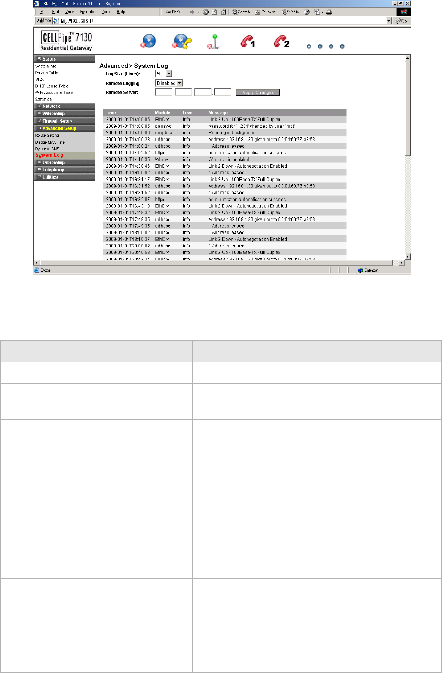
Figure 8-4 System Log window
Table 8-4 describes the fields of the System Log window.
Table 8-4 Field descriptions
Field Description
Log Size (Lines) Select the number of lines to display in your log.
Remote Logging Select LAN or WAN for the remote logging server.
Select Disable to turn off remote logging.
Remote Server Enter the IP address of the remote logging server.
Apply Changes Click to save your changes and to view the log.
Note: You can click Apply Changes to see your
report in the section of the window below the system
log fields (this is optional).
If you are configuring remote logging, click Apply
Changes after configuring the remote logging and
remote server fields.
Time The time that the action was performed.
Module The type of module the action involved.
Level Select the level of logging activity:
•Info
•Error
•Debug

System LogAdvanced Setup
............................................................................................................................................................................................................................................................
3FE-63398-AAAA-TCZZA
Edition 01 April 2009 8-7
............................................................................................................................................................................................................................................................
Message The details of the action that was performed.
Field Description
............................................................................................................................................................................................................................................................
System LogAdvanced Setup
8-8 3FE-63398-AAAA-TCZZA
Edition 01 April 2009
............................................................................................................................................................................................................................................................

9-1
3FE-63398-AAAA-TCZZA
Edition 01 April 2009
............................................................................................................................................................................................................................................................
9QoS Setup
Overview
This chapter explains how to configure the quality of service (QoS) settings of the
CellPipe 7130 RG. QoS is the ability to provide better service to selected applications and
data flows.
Click the QoS Setup drop-down menu to open the QoS Setup menu.
Contents
This chapter covers the following topics:
QoS Scheduler
The QoS Scheduler window allows you to enable and disable the scheduler protocol and
to determine the upstream bandwidth.
Select QoS Scheduler in the QoS Setup menu to access the QoS scheduler window; see
Figure 9-1.
QoS Scheduler 9-1
QoS IP Policy 9-2
QoS ALG 9-4
............................................................................................................................................................................................................................................................
QoS IP PolicyQoS Setup
9-2 3FE-63398-AAAA-TCZZA
Edition 01 April 2009
............................................................................................................................................................................................................................................................
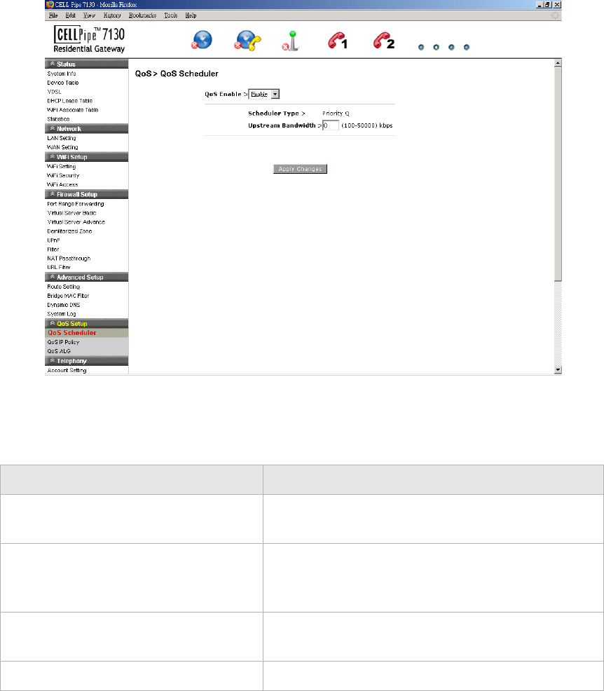
Figure 9-1 QoS Scheduler window
Table 9-1 describes the fields of the QoS Scheduler window.
Table 9-1 Field descriptions
QoS IP Policy
The QoS IP Policy window enables you to group upstream traffic into data flows
according to the source address, destination address, source port, and destination port.
Select QoS IP Policy in the QoS Setup menu to access the QoS IP Policy window; see
Figure 9-2.
Field Description
QoS Enable Select Enable to activate the QoS scheduler. Select
Disable to turn off the QoS scheduler.
Scheduler Type The QoS scheduler type is set to Priority Q. Priority
Q scheduling delivers high priority traffic first and
lower priority traffic when the queue is empty.
Upstream Bandwidth Enter an upstream bandwidth value from 100 to
50000 kb/s.
Apply Changes Click to save your changes.
QoS IP PolicyQoS Setup
............................................................................................................................................................................................................................................................
3FE-63398-AAAA-TCZZA
Edition 01 April 2009 9-3
............................................................................................................................................................................................................................................................
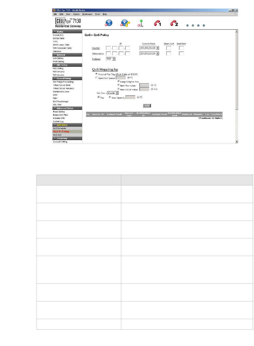
Figure 9-2 QoS IP Policy window
Table 9-2 describes the fields of the QoS IP Policy window.
Table 9-2 Field descriptions
Field Description
IP Enter the IP address of the source host and the
destination host.
Subnet Mask Select the subnet mask of the source host and the
destination host.
Start Port Enter the start port of the source host and the destination
host.
End Port Enter the end port of the source host and the destination
host.
Protocol Select the necessary protocol:
•TCP
•UDP
Original Tos Tag (First 3 bits of
DSCP)
Enable Original Tos Tag (type of service) to assign the
queue according to the incoming Tos value.
Specified Queue Enable Specified Queue and enter a queue number (0
to 7) to assign to the incoming traffic.
Keep Original Tos Enable Keep Original Tos to retain the original value.

............................................................................................................................................................................................................................................................
QoS ALGQoS Setup
9-4 3FE-63398-AAAA-TCZZA
Edition 01 April 2009
............................................................................................................................................................................................................................................................
QoS ALG
The QoS application level gateway (ALG) window enables you to configure the session
initiated protocol (SIP) and the real-time transport protocol (RTP). SIP is used for the
implementation of VoIP, and RTP is the protocol for data with real-time features (such as
interactive audio and video).
Select QoS ALG in the QoS Setup menu to access the QoS ALG window; see Figure 9-3.
New Tos Value Enable New Tos Value and enter a queue number (0 to
7) to assign to the incoming traffic.
New DSCP Value Enable New DSCP Value and enter a DSCP value (0 to
63).
Set Cos Select Enable to apply the set CoS (class of service).
Select Disable to turn off CoS.
Tos Enable To s to assign the queue according to the
incoming traffic.
User Specify Enable User Specify and enter a queue number (0 to 7)
to assign to the incoming traffic.
Add Click to save your changes.
Field Description
QoS ALGQoS Setup
............................................................................................................................................................................................................................................................
3FE-63398-AAAA-TCZZA
Edition 01 April 2009 9-5
............................................................................................................................................................................................................................................................
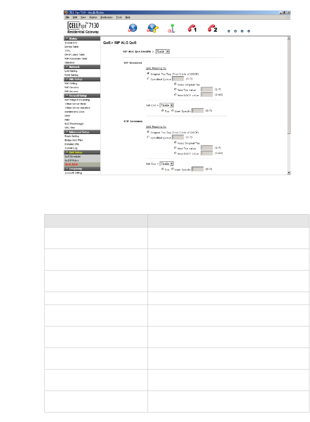
Figure 9-3 QoS ALG window
Table 9-3 describes the fields of the QoS ALG window.
Table 9-3 Field descriptions
Field Description
SIP ALG QoS Enable Select Enable to turn on the SIP and ALG QoS. Select
Disable to turn off the SIP and ALG QoS.
Original Tos Tag (First 3 bits of
DSCP)
Enable Original Tos Tag (type of service) to assign the
queue according to the incoming Tos value.
Specified Queue Enable Specified Queue and enter a queue number (0
to 7) to assign to the incoming traffic.
Keep Original Tos Enable Keep Original Tos to retain the original value.
New Tos Value Enable New Tos Value and enter a queue number (0 to
7) to assign to the incoming traffic.
New DSCP Value Enable New DSCP Value and enter a DSCP value (0 to
63).
Set Cos Select Enable to apply the set CoS (class of service).
Select Disable to turn off the set CoS.
Tos Enable To s to assign the queue according to the
incoming traffic.
User Specify Enable User Specify and enter a queue number (0 to 7)
to assign to the incoming traffic.

............................................................................................................................................................................................................................................................
QoS ALGQoS Setup
9-6 3FE-63398-AAAA-TCZZA
Edition 01 April 2009
............................................................................................................................................................................................................................................................
Apply Changes Click to save your changes.
Field Description

10-1
3FE-63398-AAAA-TCZZA
Edition 01 April 2009
............................................................................................................................................................................................................................................................
10 Telephony
Overview
The CellPipe 7130 RG Telephony menu enables you to configure the settings for your
VoIP account, service, server, and call list.
Click the Tel e p h o n y drop-down menu to open the Tel epho n y menu.
Contents
This chapter covers the following topics.
Account Setting
The VoIP account settings can be configured from the account setting section of the
telephony menu.
Note: Some account information, such as the phone number and username, is
provided by your VoIP service provider. Please have all provided information readily
available when configuring your accounts.
Select Account Setting in the Telep h ony menu to access the Account Setting window;
see Figure 10-1.
Account Setting 10-1
Service Setting 10-2
Server Setting 10-4
Call List 10-6
............................................................................................................................................................................................................................................................
Service SettingTelephony
10-2 3FE-63398-AAAA-TCZZA
Edition 01 April 2009
............................................................................................................................................................................................................................................................
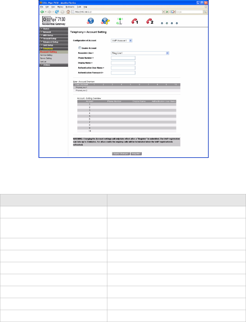
Figure 10-1 Account setting window
Table 10-1 describes the fields of the Account Setting window.
Table 10-1 Field descriptions
Service Setting
The Service Settings window enables you to configure advanced settings for the VoIP
accounts such as call waiting and three-way conference call.
Field Description
Configuration of Account Select a VoIP account to configure.
Enable Account Enable the check box to enable the account
registered to the SIP of the VoIP service provider.
Associate Line Select the phone line for the account.
Phone Number Enter the account phone number.
Display Name Enter the display name for the account.
Authentication User Name Enter the account username.
Authentication Password Enter the account password.
Apply Changes Click to save your changes.
Register Click to register your account.
Service SettingTelephony
............................................................................................................................................................................................................................................................
3FE-63398-AAAA-TCZZA
Edition 01 April 2009 10-3
............................................................................................................................................................................................................................................................
Note: Changes made to the service settings apply to all VoIP accounts.
It is recommended that you contact your VoIP service provider for assistance with
configuring the service settings. Depending on your account, some features might not
be included.
Select Service Setting in the Te leph o ny menu to access the Service Setting window; see
Figure 10-2.
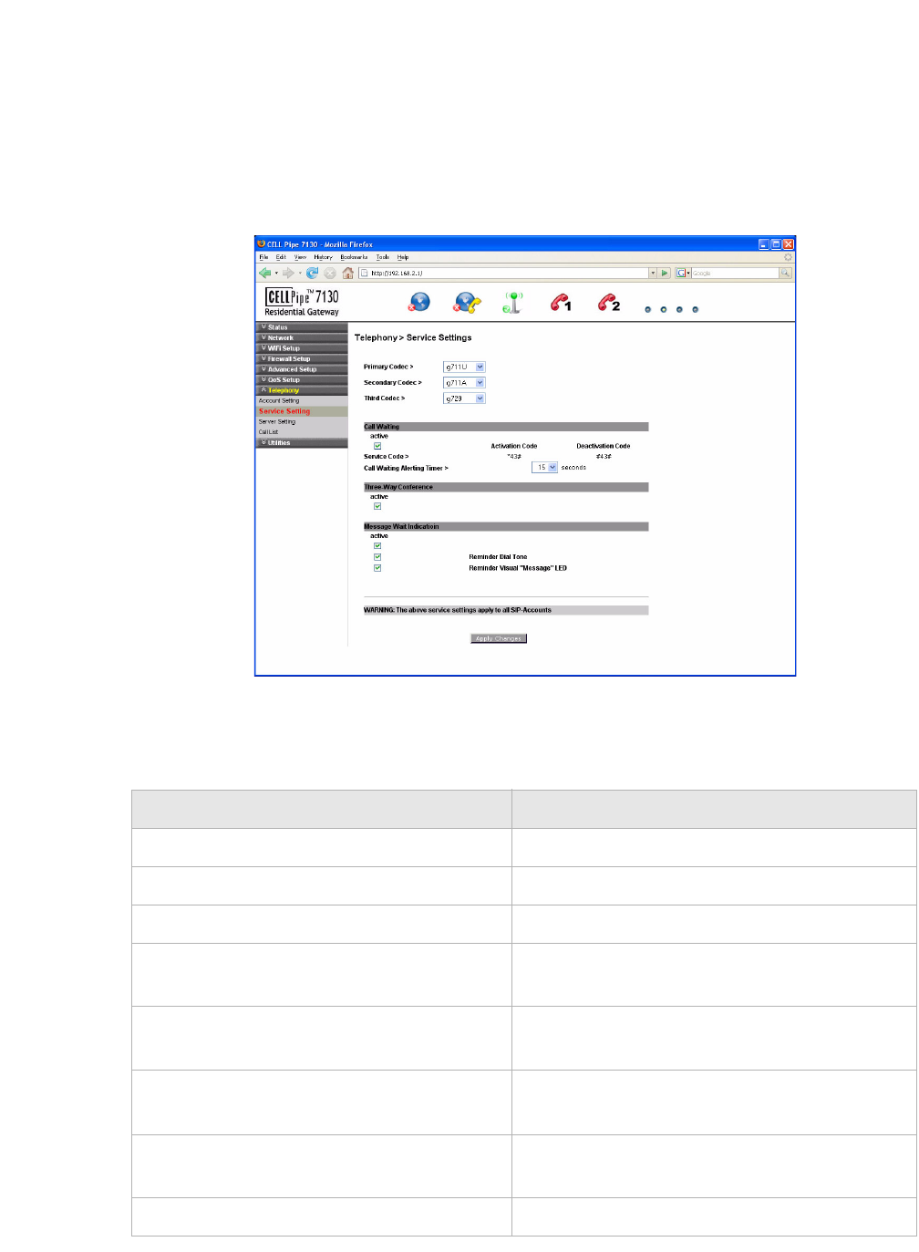
Figure 10-2 Service Setting window
Table 10-2 describes the fields of the Service Setting window.
Table 10-2 Field descriptions
Field Description
Primary Codec Select a voice coding mechanism.
Secondary Codec Select a voice coding mechanism.
Third Codec Select a voice coding mechanism.
Call Waiting Enable Active to enable the call waiting
feature.
Service Code The service codes for activation and
deactivation.
Activation Code The activation code for your call waiting
service.
Deactivation Code The deactivation code for your call waiting
service.
Call Waiting Alerting Timer Select a time interval for the call waiting alert.

............................................................................................................................................................................................................................................................
Server SettingTelephony
10-4 3FE-63398-AAAA-TCZZA
Edition 01 April 2009
............................................................................................................................................................................................................................................................
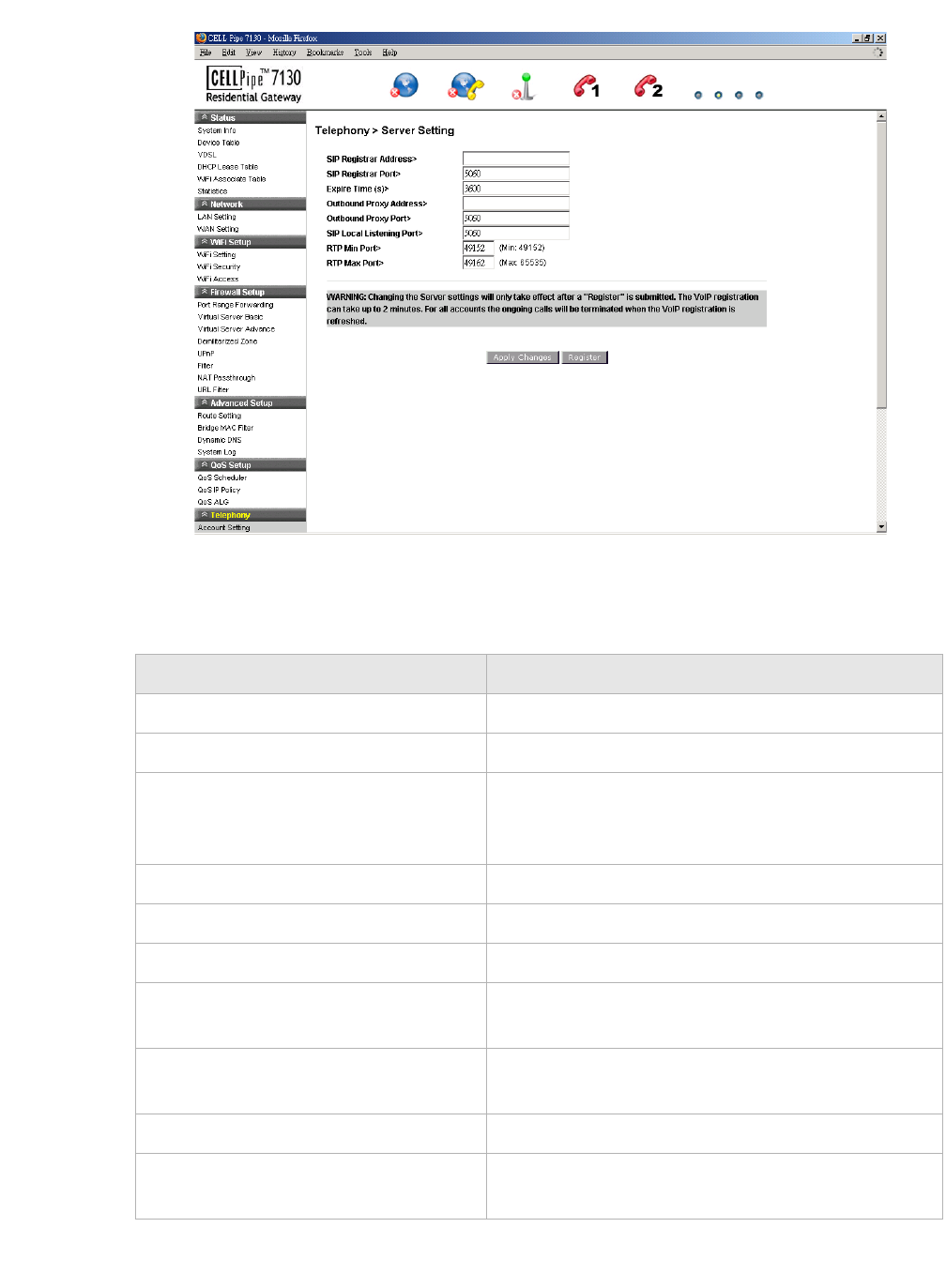
Server Setting
The Server Setting window enables you to configure the session initiated protocol (SIP)
settings for the VoIP accounts.
Note: It is recommended that you contact your VoIP service provider for assistance
with configuring the server settings.
Select Server Setting in the Tel epho n y menu to access the Server Setting window; see
Figure 10-3.
Three-Way Conference Enable Active to enable the conference call.
Message Wait Indication Enable Active to turn on the message wait
indicator. Enable one of the following as the
message wait indication:
•Reminder Dial Tone
•Reminder Visual “Message” LED
If Reminder Dial Tone is selected, the alert is
set as a dial tone. If Reminder Visual Message
LED is selected, the alert is set as an LED.
Apply Changes Click to save your changes.
Field Description
Server SettingTelephony
............................................................................................................................................................................................................................................................
3FE-63398-AAAA-TCZZA
Edition 01 April 2009 10-5
............................................................................................................................................................................................................................................................
Figure 10-3 Server Setting window
Table 10-3 describes the fields of the Server Setting window.
Table 10-3 Field descriptions
Field Description
SIP Registrar Address Enter the IP address of the SIP registration server.
SIP Registrar Port Enter the port number of the SIP registration server.
Expire Time (s) Enter the number of seconds that your SIP account is
registered with the SIP register server before it is
deleted. The default value is 3600.
Outbound Proxy Address Enter the IP address of the outbound proxy server.
Outbound Proxy Port Enter the port number of the outbound proxy server.
SIP Local Listening Port Enter the local port to listen for SIP message.
RTP Min Port Enter the minimum port range of the RTP listening
port.
RTP Max Port Enter the maximum port range of the RTP listening
port.
Apply Changes Click to save your changes.
Register Click to register the changes with your service
provider.
............................................................................................................................................................................................................................................................
Call ListTelephony
10-6 3FE-63398-AAAA-TCZZA
Edition 01 April 2009
............................................................................................................................................................................................................................................................
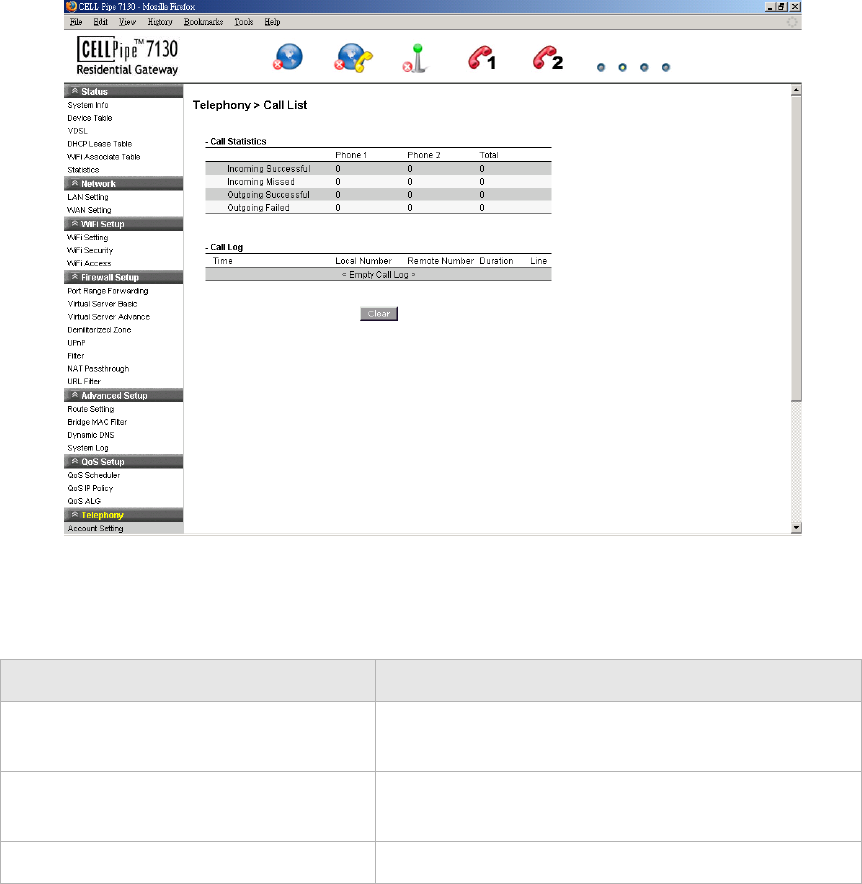
Call List
The Call List window displays the call statistics and call log of your VoIP accounts.
Select Call List in the Te leph o ny menu to access the Call List window; see Figure 10-4.
Figure 10-4 Call List window
Table 10-4 describes the fields of the Call List window.
Table 10-4 Field descriptions
Field Description
Call Statistics Displays the statistics for the incoming and outgoing
calls for VoIP accounts.
Call Log Displays the information of individual incoming and
outgoing calls.
Clear Click to clear the call statistics and call log.

11-1
3FE-63398-AAAA-TCZZA
Edition 01 April 2009
............................................................................................................................................................................................................................................................
11 Utilities
Overview
This chapter explains how to configure the utilities of the CellPipe 7130 RG.
Click the Utilities drop-down menu to open the Utilities menu.
Contents
This chapter covers the following topics:
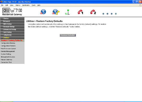
Restore Factory Defaults
The Restore Factory Defaults window enables you to restore the default settings of the
CellPipe 7130 RG.
Select Restore Factory Defaults in the Utilities menu to access the Restore Factory
Defaults window; see Figure 11-1.
Restore Factory Defaults 11-1
Configuration Backup 11-2
Configuration Restore 11-3
Web Firmware Upload 11-4
Remote Management 11-5
System Setting 11-7
Management Access 11-8
Reboot Gateway 11-9
Connection Test 11-10
............................................................................................................................................................................................................................................................
Configuration BackupUtilities
11-2 3FE-63398-AAAA-TCZZA
Edition 01 April 2009
............................................................................................................................................................................................................................................................
Figure 11-1 Restore Factory Defaults window
Click on Restore Defaults to restore the CellPipe 7130 RG to the factory default settings.
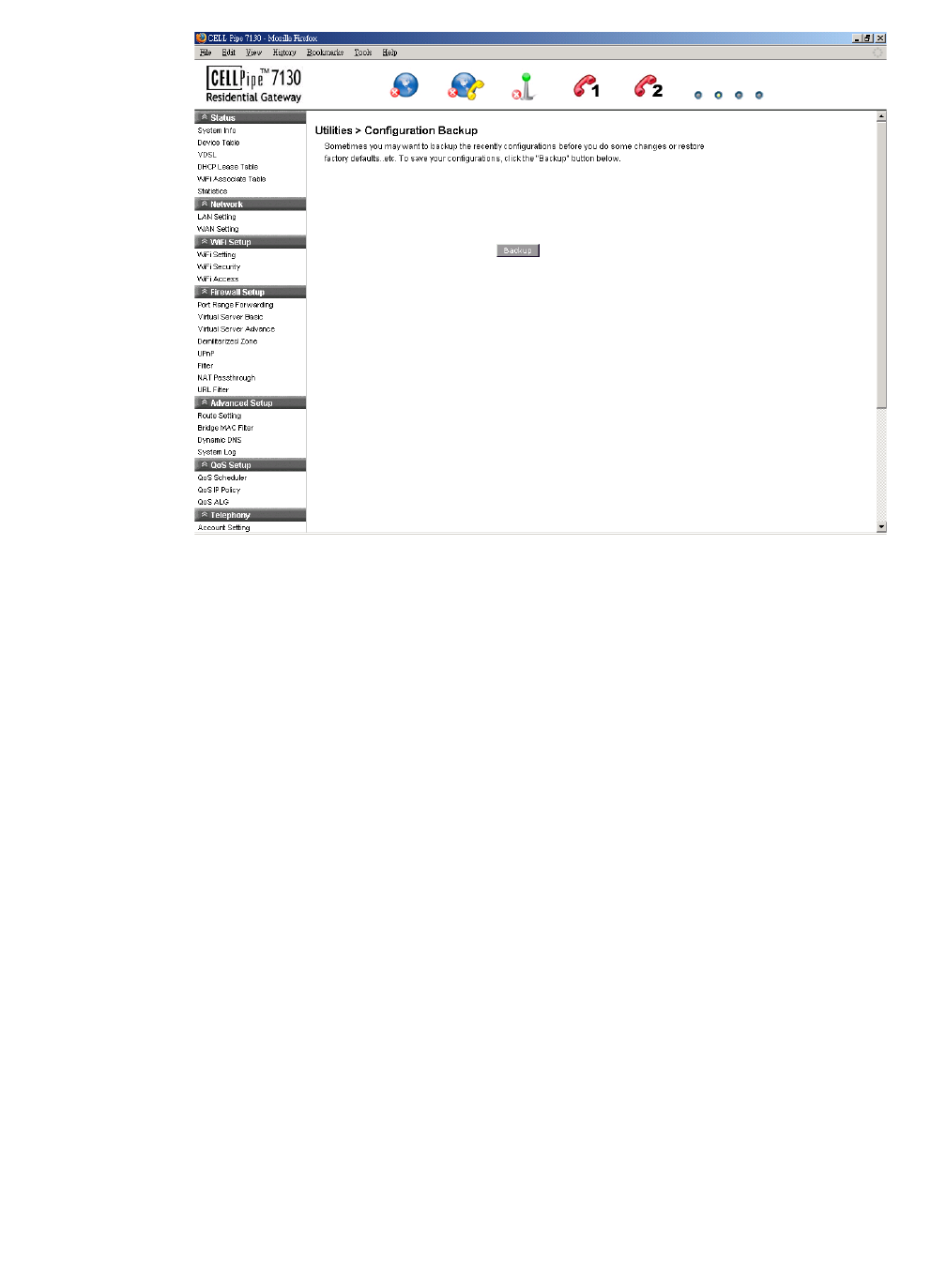
Configuration Backup
The Configuration Backup window enables you to backup your configuration of the
CellPipe 7130 RG.
Select Configuration Backup in the Utilities menu to access the Configuration Backup
window; see Figure 11-2.
Configuration RestoreUtilities
............................................................................................................................................................................................................................................................
3FE-63398-AAAA-TCZZA
Edition 01 April 2009 11-3
............................................................................................................................................................................................................................................................
Figure 11-2 Configuration Backup window
Click on Backup to save your system configuration.
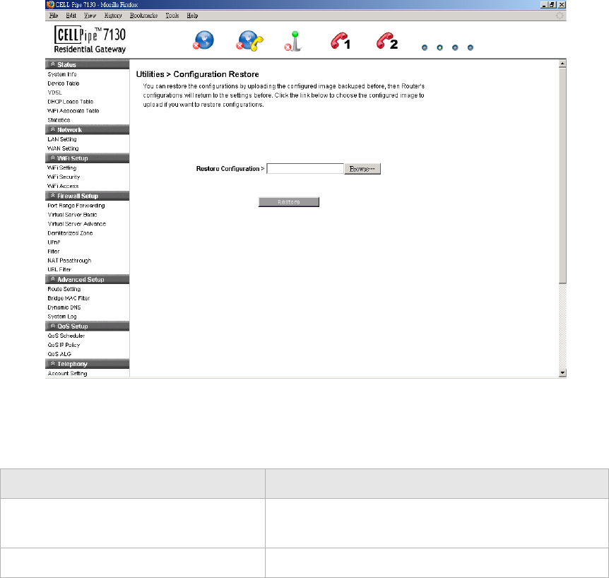
Configuration Restore
The Configuration Restore window enables you to restore your configuration of the
CellPipe 7130 RG.
Select Configuration Restore in the Utilities menu to access the Configuration Restore
window; see Figure 11-3.
............................................................................................................................................................................................................................................................
Web Firmware UploadUtilities
11-4 3FE-63398-AAAA-TCZZA
Edition 01 April 2009
............................................................................................................................................................................................................................................................
Figure 11-3 Configuration Restore window
Table 11-1 describes the fields of the Configuration Restore window.
Table 11-1 Field descriptions
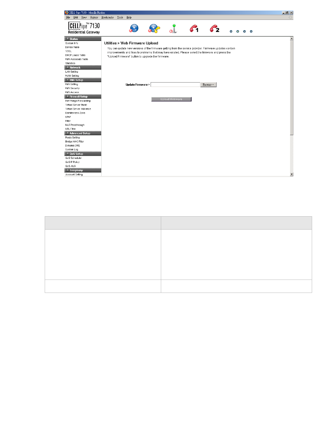
Web Firmware Upload
The Web Firmware Upload window enables you to update the firmware for the CellPipe
7130 RG.
WARNING
Do not turn off the power or disturb the system during a firmware upgrade.
Select Web Firmware Upload in the Utilities menu to access the Web Firmware Upload
window; see Figure 11-4.
Field Description
Restore Configuration Click Browse and then locate and select the
configuration backup file to restore.
Restore Click to restore the selected configuration.
Remote ManagementUtilities
............................................................................................................................................................................................................................................................
3FE-63398-AAAA-TCZZA
Edition 01 April 2009 11-5
............................................................................................................................................................................................................................................................
Figure 11-4 Web Firmware Upload window
Table 11-2 describes the fields of the Web Firmware Upload window.
Table 11-2 Field descriptions
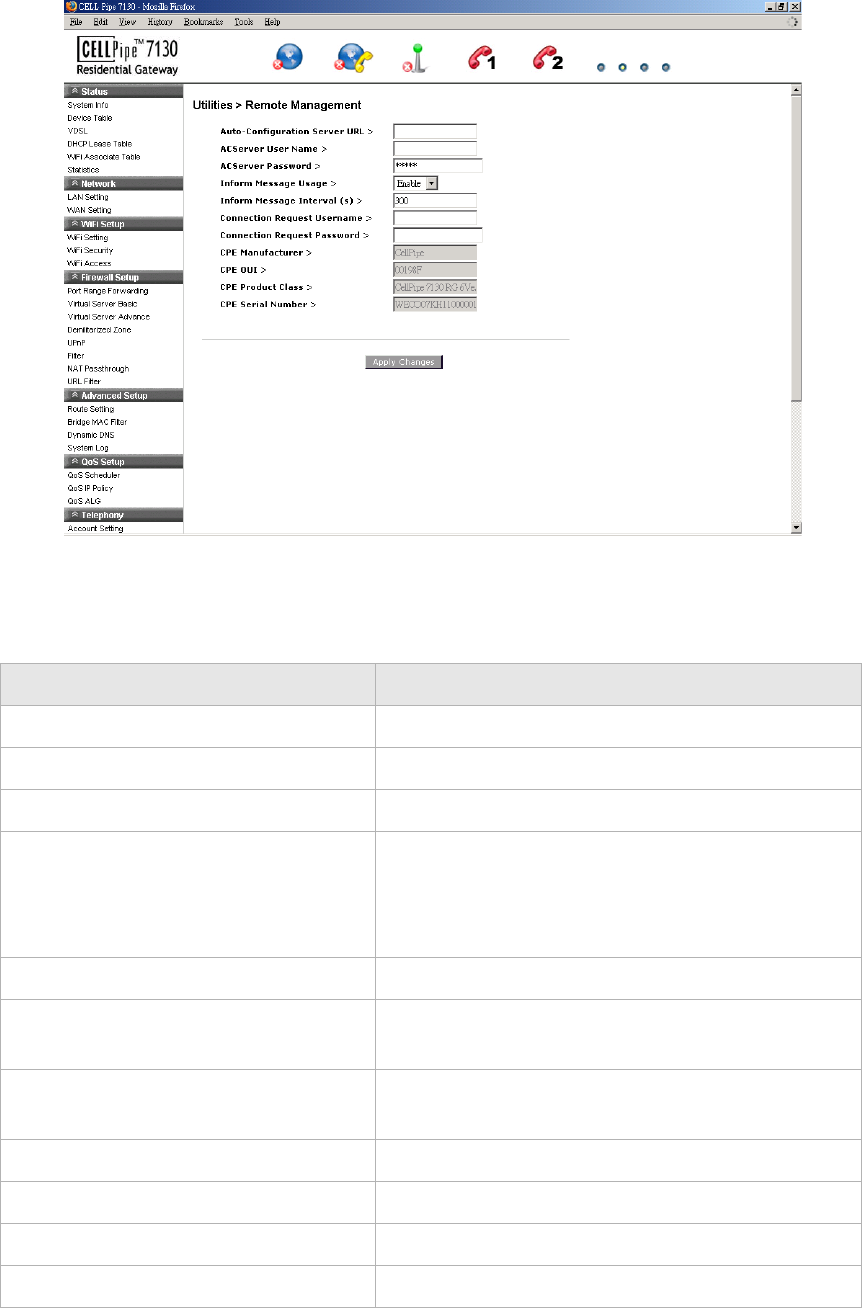
Remote Management
The Remote Management window enables you to configure remote access of the CellPipe
7130 RG.
Select Remote Management in the Utilities menu to access the Remote Management
window; see Figure 11-5.
Field Description
Update Firmware Click Browse to locate and select the firmware
upgrade file to upload.
Note: Firmware upgrades are available at
http://www.alcatel-lucent.com/wps/portal/support.
You must obtain the upgrade file before uploading.
Upload Firmware Click to upload the firmware update.
............................................................................................................................................................................................................................................................
Remote ManagementUtilities
11-6 3FE-63398-AAAA-TCZZA
Edition 01 April 2009
............................................................................................................................................................................................................................................................
Figure 11-5 Remote Management window
Table 11-3 describes the fields of the Remote Management window.
Table 11-3 Field descriptions
Field Description
Auto-Configuration Server URL Enter the URL of the auto-configuration server.
ACServer User Name Enter the username of the auto-configuration server.
ACServer Password Enter the password for the auto-configuration server.
Inform Message Usage Select Enable to have the device information sent to
the auto-configuration server. Select Disable not to
send the information to the auto-configuration
server.
Inform Message Interval (s) Enter an interval of time in seconds.
Connection Request User Name Enter the username for the connection request of the
auto-configuration server to the device.
Connection Request Password Enter the password for the connection request of the
auto-configuration server to the device.
CPE Manufacturer The manufacturer of the device.
CPE OUI The organizational unique identifier of the device.
CPE Product Class The model of the device.
CPE Serial Number The serial number of the device.
System SettingUtilities
............................................................................................................................................................................................................................................................
3FE-63398-AAAA-TCZZA
Edition 01 April 2009 11-7
............................................................................................................................................................................................................................................................
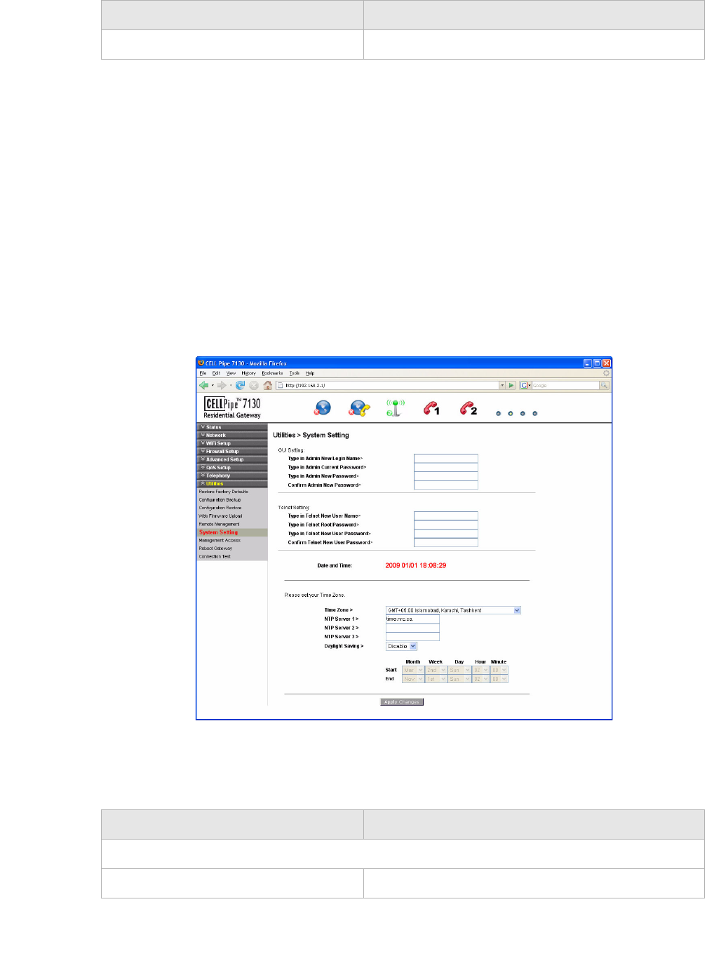
System Setting
The System Setting window enables you to change the web administrator username and
password, and configure settings such as the time zone, NTP, and daylight savings.
Note: It is highly recommended that you change the admin default username and
password and the Telnet default username and password.
Select System Setting in the Utilities menu to access the System Setting window; see
Figure 11-6.
Figure 11-6 System Setting window
Table 11-4 describes the fields of the System Setting window.
Table 11-4 Field descriptions
Apply Changes Click to save your changes.
Field Description
Field Description
GUI Setting
Type in Admin New Login Name Enter the new username.

............................................................................................................................................................................................................................................................
Management AccessUtilities
11-8 3FE-63398-AAAA-TCZZA
Edition 01 April 2009
............................................................................................................................................................................................................................................................
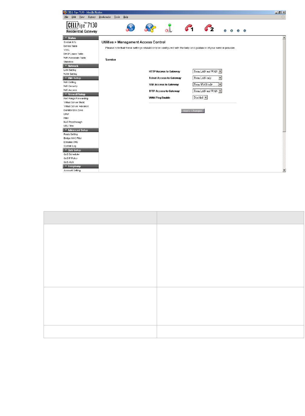
Management Access
The Management Access window enables you to control the types of services that pass
through the router and provide a layer of security.
Note: It is recommended that you consult your ISP before configuring the access.
Select Management Access in the Utilities menu to access the Management Access
window; see Figure 11-7.
Type in Admin Current Password Enter the current admin password.
Note: If this is the first time the admin password is
changed, the default admin password is admin.
Type in Admin New Password Enter the new password.
Confirm Admin New Password Retype the new password to confirm.
Telnet Setting
Type in Telnet New User Name Enter the new username.
Type in Telnet Root Password Enter the current Telnet root password.
Note: If this is the first time the root password is
changed, the default root password is c@a*sh=G!.
Type in Telnet New User Password Enter the new password.
Confirm Telnet New User Password Retype the new password to confirm.
Please set your Time Zone
Date and Time Displays the current date and time according to the
time zone configuration.
Time Zone Select your time zone.
NTP Server 1 to 3 Enter the IP address or URL of the network time
protocol server.
Daylight Saving Select Enable to turn on daylight savings time.
Select Disable to turn off daylight savings time.
Start/End If you have enabled daylight savings time, select the
required Month, Week, Day, Hour, and Minute
for the daylight savings time to take effect.
Apply Changes Click to save your changes.
Field Description
Reboot GatewayUtilities
............................................................................................................................................................................................................................................................
3FE-63398-AAAA-TCZZA
Edition 01 April 2009 11-9
............................................................................................................................................................................................................................................................
Figure 11-7 Management Access window
Table 11-5 describes the fields of the Management Access window.
Table 11-5 Field descriptions
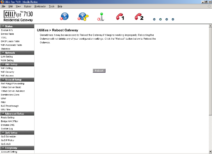
Reboot Gateway
The Reboot Gateway window enables you to reboot the CellPipe 7130 RG. Rebooting the
gateway does not reset your settings.
Field Description
HTTP Access to Gateway
Telnet Access to Gateway
SSH Access to Gateway
TFTP Access to Gateway
Select one of the following settings:
•Disable
•From LAN only
•From WAN only
•From LAN and WAN
WAN Ping Enable Select Enable to allow the WAN interface to
respond to the ICMP request from the Internet.
Select Disable to deny the WAN interface from
responding to the ICMP request from the Internet.
Apply Changes Click to save your changes.
............................................................................................................................................................................................................................................................
Connection TestUtilities
11-10 3FE-63398-AAAA-TCZZA
Edition 01 April 2009
............................................................................................................................................................................................................................................................
Select Reboot Gateway in the Utilities menu to access the Reboot Gateway window; see
Figure 11-8.
Figure 11-8 Reboot Gateway window
Click on Reboot to restart the CellPipe 7130 RG.
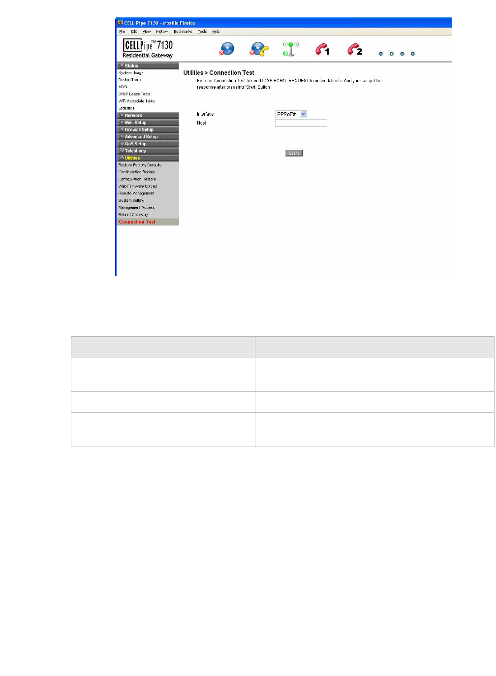
Connection Test
The Connection Test screen enables you to test the connectivity with other network
devices.
Select Connection Test in the Utilities menu to access the Connection Test window; see
Figure 11-9.
Connection TestUtilities
............................................................................................................................................................................................................................................................
3FE-63398-AAAA-TCZZA
Edition 01 April 2009 11-11
............................................................................................................................................................................................................................................................
Figure 11-9 Connection Test window
Figure 11-6 describes the fields of the Connection Test window.
Table 11-6 Field descriptions
Field Description
Interface From the drop-down menu, select the interface to
which the device to be tested is connected.
Host Please enter the IP address of the device to be tested.
Start Click Start to test the connection of the selected
device.
............................................................................................................................................................................................................................................................
Connection TestUtilities
11-12 3FE-63398-AAAA-TCZZA
Edition 01 April 2009
............................................................................................................................................................................................................................................................

A-1
3FE-63398-AAAA-TCZZA
Edition 01 April 2009
............................................................................................................................................................................................................................................................
A Troubleshooting
Overview
This section identifies common problems that can arise during the use of the CellPipe
7130 RG (and offers solutions). Most issues are identified by the LEDs on the front panel
of the CellPipe 7130 RG.
Troubleshooting Table
Symptom Possible cause Solution
Power LED does not
come on after power is
switched on.
Outlet, power cord, or power
adapter might be defective.
•Check the outlet by
plugging in another
electronic device.
•Call the customer service
number or return the device
to the vendor.
DSL LED flashes
slowly after connection
is established.
The VDSL port on the gateway
or the cable might be defective.
•Switch the power off and
then switch the power on.
•Verify that the cable is
connected properly to the
VDSL wall line and the
VDSL connector on the
CellPipe 7130 RG.
LAN LED does not
come on after
connection is
established.
The LAN port on the gateway,
the network interface, or a
network cable may be defective
or not connected.
•Verify that the power is
switched on.
•Ensure that the cable is
plugged into the CellPipe
7130 RG and the device.
•Check the network adapter
or the cable connections for
defects.
VDSL Diag LED is
flashing.
A firmware upgrade is in
progress.
•Verify that a firmware
upgrade is in progress.
•Wait until the firmware
upgrade is finished.

............................................................................................................................................................................................................................................................
OverviewTroubleshooting
A-2 3FE-63398-AAAA-TCZZA
Edition 01 April 2009
............................................................................................................................................................................................................................................................
Internet LED is off. Your device is unable to connect
to the Internet. The device might
not be configured properly or
the network adapter driver might
need to be updated.
•Verify that your device is
properly configured for
TCP/IP.
•Ensure that the correct
network adapter driver is
installed for your operating
system. If necessary,
reinstall the driver.
•Check that the speed of the
network adapter or duplex
mode has not been
configured manually. It is
recommended that the
adapter be set to auto-
negotiation.
•Ensure that the network
connection is established
before launching the
browser.
•In the network connection
tab, verify that your user
name and password are
correct.
Symptom Possible cause Solution

B-1
3FE-63398-AAAA-TCZZA
Edition 01 April 2009
............................................................................................................................................................................................................................................................
B TCP/IP configuration
Overview
The following procedures provide TCP/IP configuration instructions for all supported
operating systems.
Windows Vista
1. Open Network and sharing Center from the Control Panel.
2. Open Manage network connections from the Network and sharing Center.
3. Right-click Ethernet connection and select Properties.
4. Under the General tab, select Internet Protocol (TCP/IPv4), and click Properties.
5. Select the Obtain an IP address automatically radio button.
6. Select the Obtain DNS server address automatically radio button.
7. Click OK to save the settings.
........................................................................................................................................................
END OF STEPS
Windows XP
1. Open Network Connections from the Control Panel.
2. Right-click Ethernet connection and select Properties.
3. Under the General tab, select Internet Protocol (TCP/IP), and click Properties. The
Internet Protocol (TCP/IP) properties window appears.
4. Select the Obtain an IP address automatically radio button.
5. Select the Obtain DNS server address automatically radio button.
6. Click OK to save the settings.
........................................................................................................................................................
END OF STEPS
Windows Me/2000/98/95
1. Open Network and Dialing Connections from the Control Panel.
2. Right click the Ethernet connection icon and select Properties.
3. Select Internet Protocol (TCP/IP) component, and click Properties. The Internet
Protocol (TCP/IP) properties window appears.

............................................................................................................................................................................................................................................................
OverviewTCP/IP configuration
B-2 3FE-63398-AAAA-TCZZA
Edition 01 April 2009
............................................................................................................................................................................................................................................................
4. Select the Obtain an IP address automatically radio button.
5. Select the Obtain DNS server address automatically radio button.
6. Click OK to save the settings.
........................................................................................................................................................
END OF STEPS
Windows NT
1. Open Network from the Control Panel.
2. From the Protocol tab, select the Internet Protocol (TCP/IP) component, and click
the Properties button.
3. From the IP Address tab, select the Obtain an IP address automatically radio button.
4. From the DNS tab, verify that no DNS server is defined in the DNS Service Search
Order box and no suffix is defined in the Domain Suffix Search Order box.
........................................................................................................................................................
END OF STEPS
Mac OS
1. Open System Preferences from the Panel.
2. Choose Network from Internet & Network.
3. Make sure the window is unlocked. If it is locked, click the lock to make changes and
enter the password for authentication.
4. From the TCP/IP tab, choose the Using DHCP on Configure IPv4 field.
5. Click on the Apply Now button to obtain an IP address from the DHCP server.
........................................................................................................................................................
END OF STEPS

C-1
3FE-63398-AAAA-TCZZA
Edition 01 April 2009
............................................................................................................................................................................................................................................................
C Product conformance
Overview
This section lists the product conformance requirements for the EU.
EU declaration of conformity
This device complies with the essential requirements of the R&TTE Directive 1999/5/EC.
The following test methods have been applied in order to prove presumption of conformity
with the essential requirements of the R&TTE Directive 1999/5/EC:
•EN60950-1:2001 A11:2004
Safety of Information Technology Equipment
•EN50385 : (2002-08)
Product standard to demonstrate the compliance of radio base stations and fixed
terminal stations for wireless telecommunication systems with the basic restrictions or
the reference levels related to human exposure to radio frequency electromagnetic
fields (110MHz - 40 GHz) - General public
•EN 300 328 V1.7.1: (2006-10)
Electromagnetic compatibility and Radio spectrum Matters (ERM); Wideband
Transmission systems; Data transmission equipment operating in the 2,4 GHz ISM
band and using spread spectrum modulation techniques; Harmonized EN covering
essential requirements under article 3.2 of the R&TTE Directive
•EN 301 489-1 V1.6.1: (2005-09)
Electromagnetic compatibility and Radio Spectrum Matters (ERM); ElectroMagnetic
Compatibility (EMC) standard for radio equipment and services; Part 1: Common
technical requirements
•EN 301 489-17 V1.2.1 (2002-08)
Electromagnetic compatibility and Radio spectrum Matters (ERM); ElectroMagnetic
Compatibility (EMC) standard for radio equipment and services; Part 17: Specific
conditions for 2,4 GHz wideband transmission systems and 5 GHz high performance
RLAN equipment
............................................................................................................................................................................................................................................................
EU declaration of conformityProduct conformance
C-2 3FE-63398-AAAA-TCZZA
Edition 01 April 2009
............................................................................................................................................................................................................................................................
This device is a 2.4 GHz wideband transmission system (transceiver), intended for use in
all EU member states and EFTA countries, except in France and Italy where restrictive use
applies.
In Italy the end-user should apply for a license at the national spectrum authorities in order
to obtain authorization to use the device for setting up outdoor radio links and/or for
supplying public access to telecommunications and/or network services.
This device may not be used for setting up outdoor radio links in France and in some areas
the RF output power may be limited to 10 mW EIRP in the frequency range of 2454 –
2483.5 MHz. For detailed information the end-user should contact the national spectrum
authority in France.
Federal Communication Commission Interference Statement
This equipment has been tested and found to comply with the limits for a Class B digital device,
pursuant to Part 15 of the FCC Rules. These limits are designed to provide reasonable
protection against harmful interference in a residential installation. This equipment generates,
uses and can radiate radio frequency energy and, if not installed and used in accordance with
the instructions, may cause harmful interference to radio communications. However, there is
no guarantee that interference will not occur in a particular installation. If this equipment does
cause harmful interference to radio or television reception, which can be determined by turning
the equipment off and on, the user is encouraged to try to correct the interference by one of the
following measures:
- Reorient or relocate the receiving antenna.
- Increase the separation between the equipment and receiver.
- Connect the equipment into an outlet on a circuit different from that to which the receiver is
connected.
- Consult the dealer or an experienced radio/TV technician for help.
FCC Caution: Any changes or modifications not expressly approved by the party responsible for
compliance could void the user's authority to operate this equipment.
This device complies with Part 15 of the FCC Rules. Operation is subject to the following two
conditions: (1) This device may not cause harmful interference, and (2) this device must accept
any interference received, including interference that may cause undesired operation.
IMPORTANT NOTE:
FCC Radiation Exposure Statement:
This equipment complies with FCC radiation exposure limits set forth for an uncontrolled
environment. This equipment should be installed and operated with minimum distance 20 cm
between the radiator & your body.
This transmitter must not be co-located or operating in conjunction with any other antenna or
transmitter.
The availability of some specific channels and/or operational frequency bands are country
dependent and are firmware programmed at the factory to match the intended destination. The
firmware setting is not accessible by the end user.
FCC REQUIREMENTS
This equipment complies with Part 68 of FCC Rules and the requirements adopted by
the ACTA.. On the bass unit of this equipment is a label that contains, among other
information, a product identifier in the format US: GEMDL01B WVDK118. If requested, this
number must be provided to the telephone company. The REN for this product is part of
the product identifier that has the format US: GEMDL01B WVDK118. The digits
represented by 01 are the REN without a decimal point.
The REN is useful to determine the quantity of devices you may connect to your
telephone line and still have those devices ring when your telephone number is called.
In most, but not all areas, the sum of the REN of all devices connected to one line
should not exceed five (5.0). To be certain of the number of devices you may connect
to your line, as determined by the REN, you should contact your local telephone
company to determine the maximum REN for your calling area.
If your equipment causes harm to the telephone network, the telephone company
may discontinue your service temporarily. If possible, they will notify you in advance. If
advance notice is not practical, you will be notified as soon as possible. You will be
informed of your right to file a complaint with the FCC. Your telephone company may
make changes in its facilities, equipment, operations or procedures that could affect
the proper functioning of your equipment. If they do, you will be notified in advance to
give you an opportunity to maintain uninterrupted telephone service.
If you experience trouble with this telephone equipment, please contact the following
address and phone number for information on obtaining service or repairs:
The telephone company may ask that you disconnect this equipment from the network
until the problem has been corrected or until you are sure that the equipment is not
malfunctioning.
This equipment may not be used on coin service provided by the telephone company.
Connection to party lines is subject to state tariffs.

GL-1
3FE-63398-AAAA-TCZZA
Edition 01 April 2009
............................................................................................................................................................................................................................................................
Glossary
Numerics
10/100Base-T
The most widely used standard for Ethernet over twisted pair or copper-based
computer networking. Runs at 10 Mb/s, 100 Mb/s, and 1000 Mb/s (1 Gb/s)
respectively.
802.1 Q/P
The standard that allows multiple bridged networks to transparently share the same
physical network link without leakage of information between networks.
A
ACS
Auto-Configuration Server
ALG
Application-Level Gateway
AP
Access Point
API
Application Programming Interface
C
CHAP
Challenge-Handshake Authentication Protocol
Codec
A device or computer program capable of encoding and/or decoding a digital data
stream or signal.
CoS
Class of Service
CPE
Customer Premises Equipment
D
DDNS
Dynamic Domain Name System
DHCP
Dynamic Host Configuration Protocol
DMZ
Demilitarized Zone
............................................................................................................................................................................................................................................................
Glossary
GL-2 3FE-63398-AAAA-TCZZA
Edition 01 April 2009
............................................................................................................................................................................................................................................................
DNS
Domain Name System
DSCP
Differentiated Services Code Point
DSL
Digital Subscriber Line
DTIM
Delivery Traffic Indication Message
Dynamic Routing
The capability of a system, through which routes are characterised by their destination,
to alter the path that the route takes through the system in response to a change in
conditions.
E
Ethernet
A family of frame-based computer networking technologies for local area networks
(LANs).
F
Firewall
An integrated collection of security measures designed to prevent unauthorized
electronic access to a networked computer system.
G
Gateway
A network node equipped for interfacing with another network that uses different
protocols.
H
HTML
Hyper Text Markup Language
I
IP
Internet Protocol
IPSec
Internet Protocol Security
ISP
Internet Service Provider
K
kb/s
Kilobit per second; a data rate unit.

Glossary
GL-3
3FE-63398-AAAA-TCZZA
Edition 01 April 2009
............................................................................................................................................................................................................................................................
............................................................................................................................................................................................................................................................
L
L2TP
Layer 2 tunneling protocol; a tunneling protocol used to support virtual private
networks (VPNs).
LAN
Local Area Network
M
MAC
Media Access Control
Mb
Megabit; a unit of information commonly used to express the rate data is transferred.
MTU
Maximum Transmission Unit
N
NAT
Network Address Translation
Netmask
The designated IP address routing prefix for a network of computers and devices.
NIC
Network Interface Controller
NTP
Network Time Protocol
O
OUI
Organizationally Unique Identifier
Outbound Proxy Server
The server responsible for handling calls made behind the NAT device by examining
and translating the IP addresses.
P
PAP
Password Authentication Protocol
Ping
A computer network tool used to test whether a particular host is reachable across an
IP network.
PPPoE
Point-to-Point Protocol over Ethernet
PPTP
Point-to-Point Tunneling Protocol
............................................................................................................................................................................................................................................................
Glossary
GL-4 3FE-63398-AAAA-TCZZA
Edition 01 April 2009
............................................................................................................................................................................................................................................................
PSK
Pre-Shared Key
Q
QoS
Quality of Service
R
RJ-11
A physical interface often used for terminating telephone wires.
RJ-45
Most regularly used as an Ethernet connector. RJ-45 connectors are typically used to
terminate twisted pair cable.
RTP
Real-time Transport Protocol; handles voice data transfer making VOIP call using SIP.
S
SSH
Secure Shell
SIP
Session Initiation Protocol; an application layer control protocol that handles the
setting up, altering and tearing down of voice and multimedia sessions over the
Internet.
SSID
Service Set Identifier
Subnet
See Netmask.
T
TCP
Transmission Control Protocol
Tel ne t
Telecommunications network; a network protocol used on the internet or local area
network (LAN) connections.
TFTP
Trivial File Transfer Protocol
To S
Type of Service
U
UDP
User Datagram Protocol

Glossary
GL-5
3FE-63398-AAAA-TCZZA
Edition 01 April 2009
............................................................................................................................................................................................................................................................
............................................................................................................................................................................................................................................................
UPnP
Universal Plug and Play
URL
Uniform Resource Locator
V
VDSL
Very High Bitrate Digital Subscriber Line
VLAN
Virtual Local Area Network
VoIP
Voice over Internet Protocol
W
WAN
Wide Area Network
WDS
Wireless Distribution System
WEP
Wired Equivalent Privacy
WiFi
Wireless networking compatibility
WLAN
Wireless Local Area Network
WPA
WiFi Protected Access
WPS
WiFi Protected Setup
............................................................................................................................................................................................................................................................
Glossary
GL-6 3FE-63398-AAAA-TCZZA
Edition 01 April 2009
............................................................................................................................................................................................................................................................