GemTek Technology WVVDB-101N 7130 Residential Gateway 6Vz.A2131 User Manual 6Ve AB2131
Gemtek Technology Co., Ltd. 7130 Residential Gateway 6Vz.A2131 6Ve AB2131
UserManual.wiki
>
GemTek Technology
>
WVVDB 101N User Manual
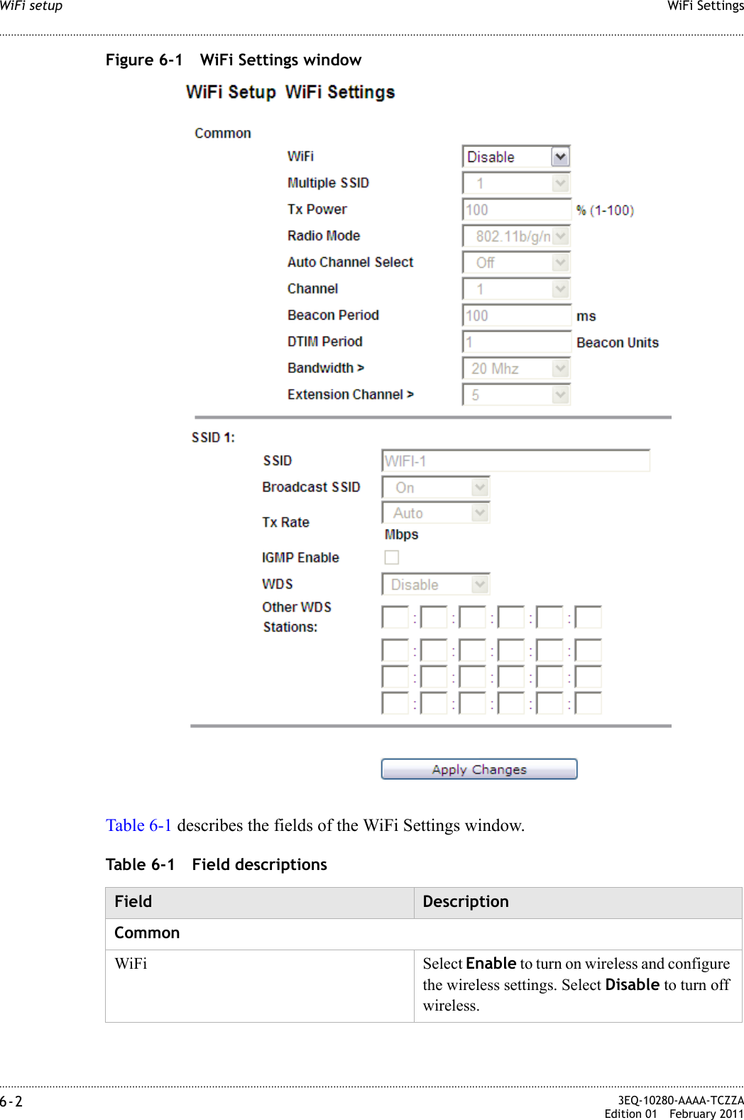
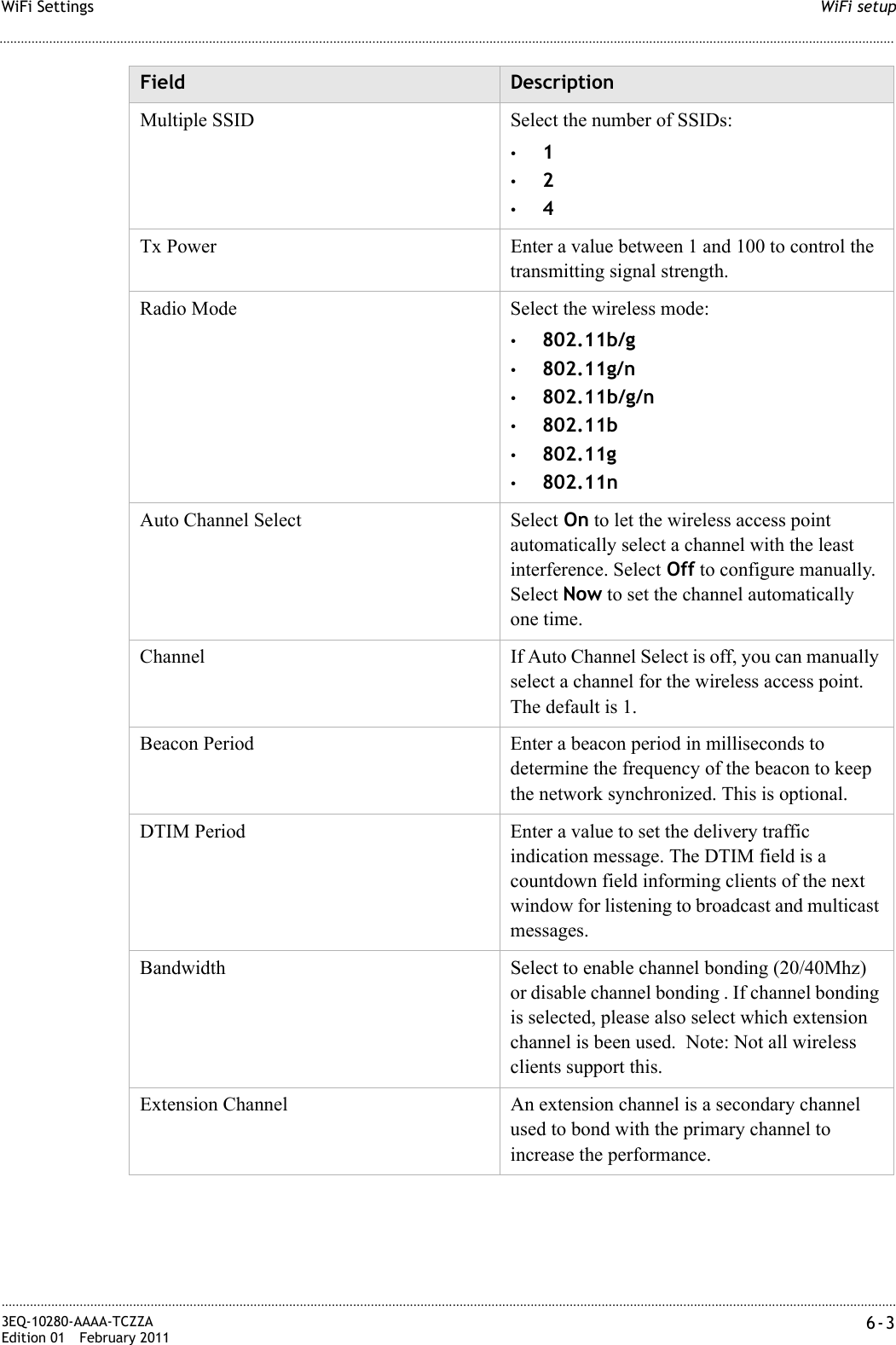
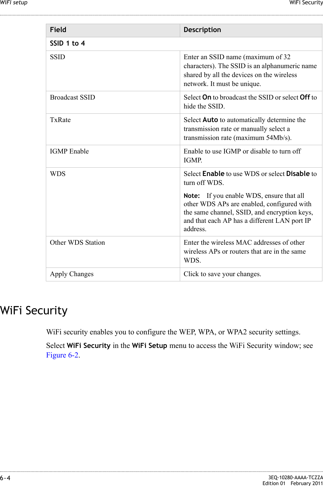
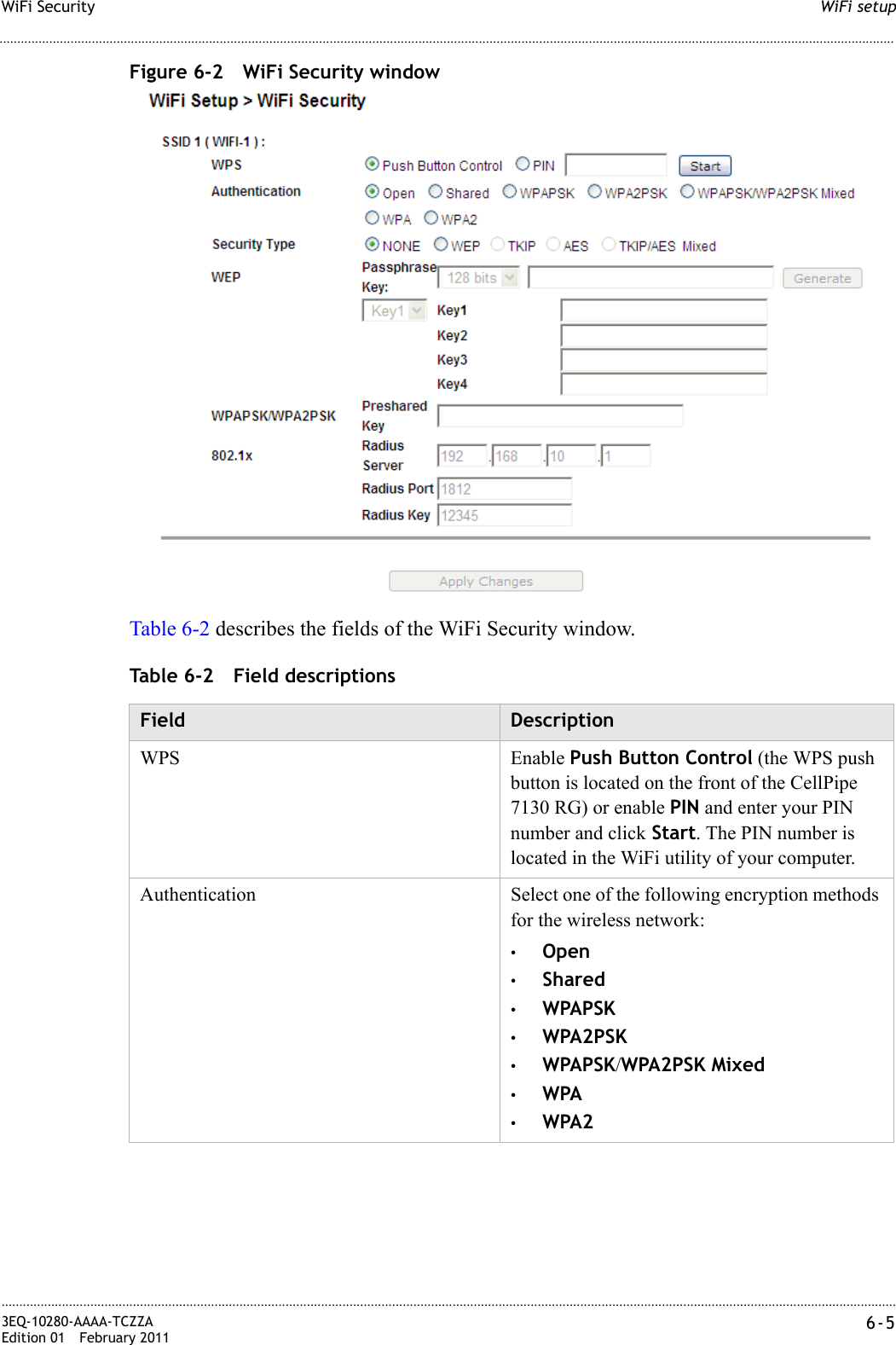
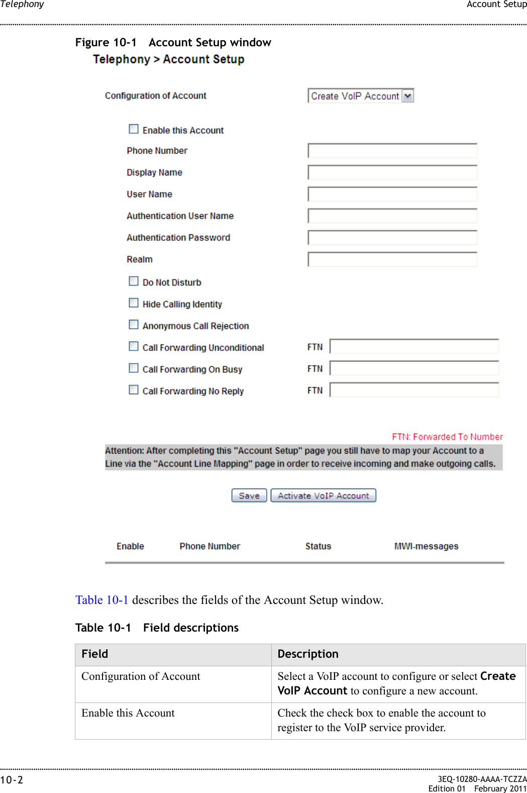
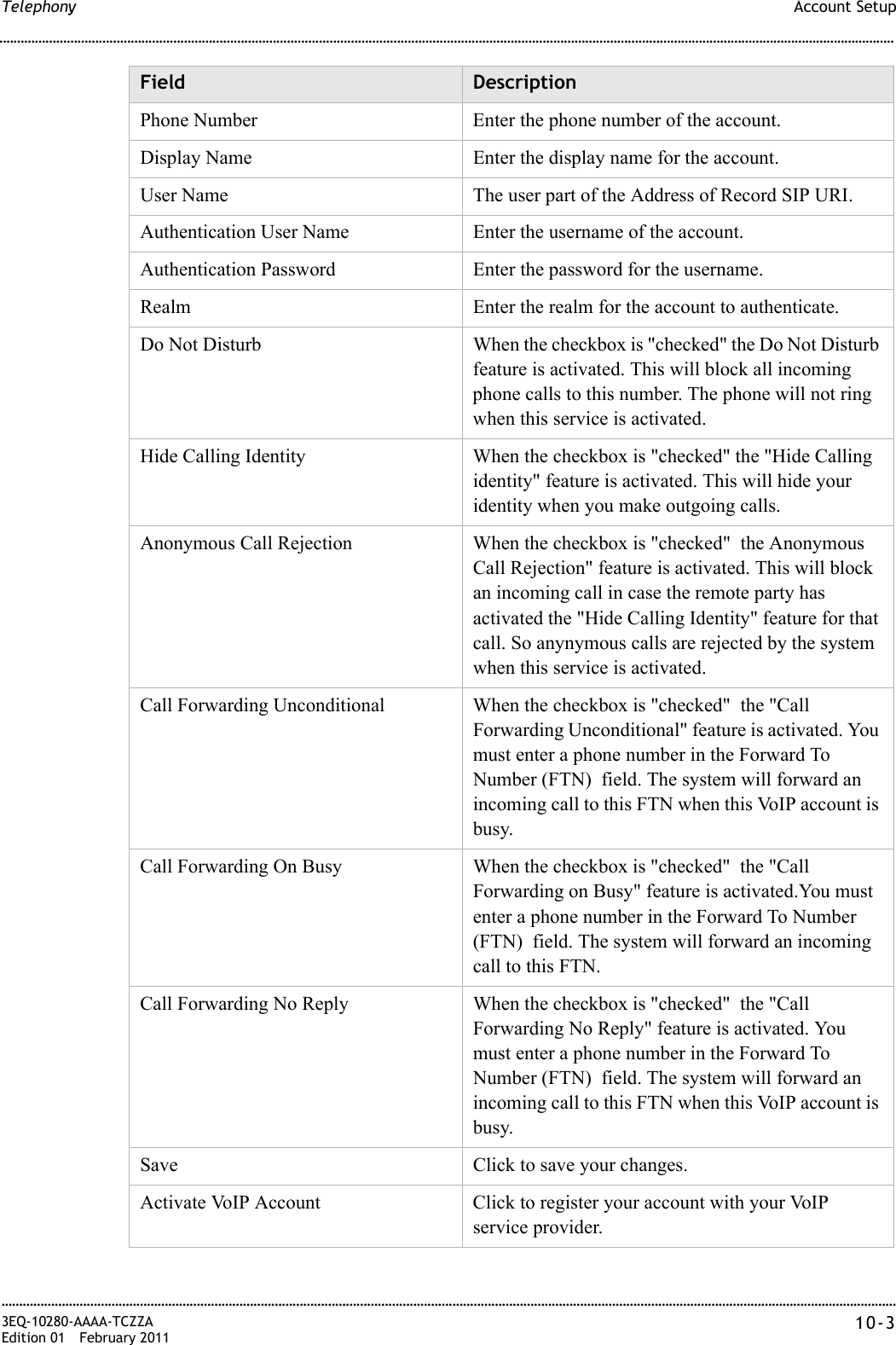
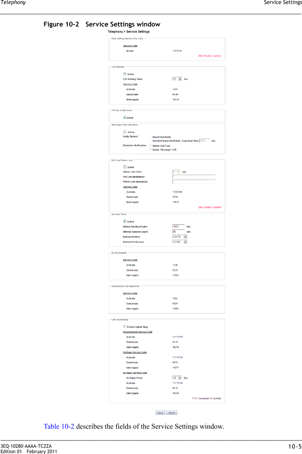
User Manual
Navigation menu
Upload a User Manual
Namespaces
Wiki Guide
HTML
PDF
Info
Views
User Manual
Discussion / Help
Navigation
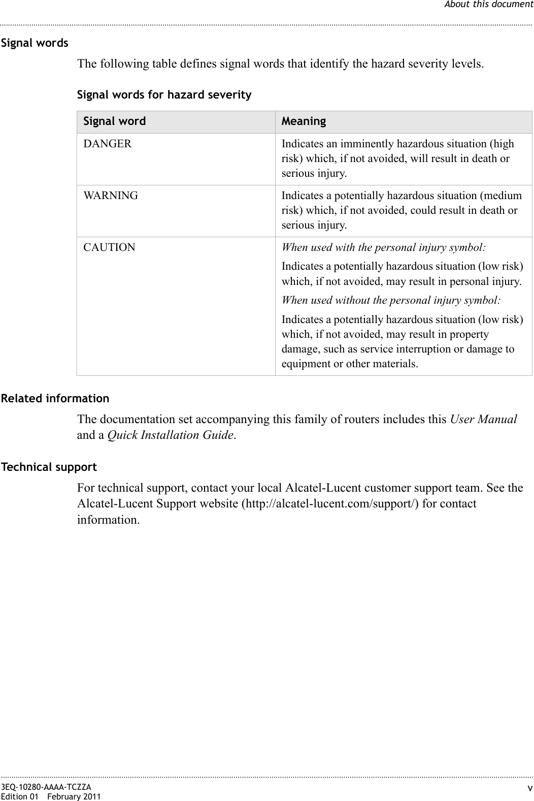


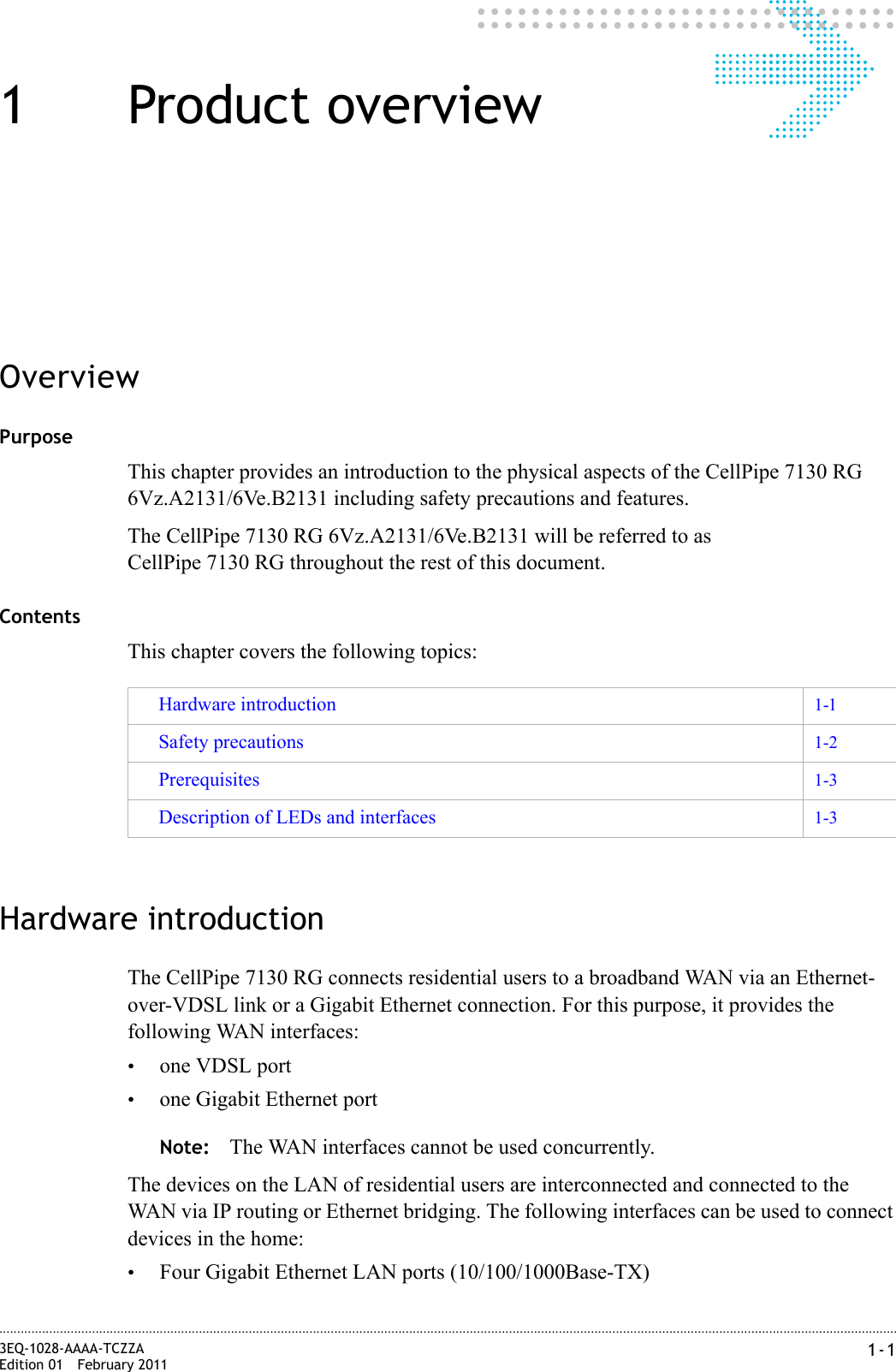
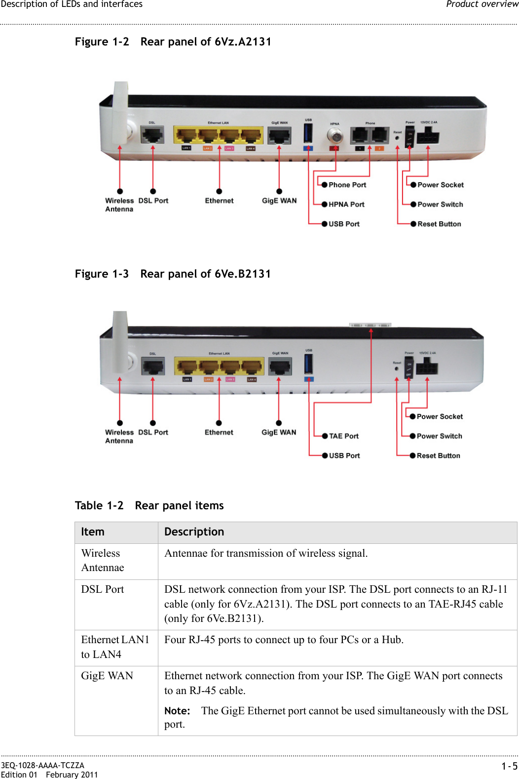
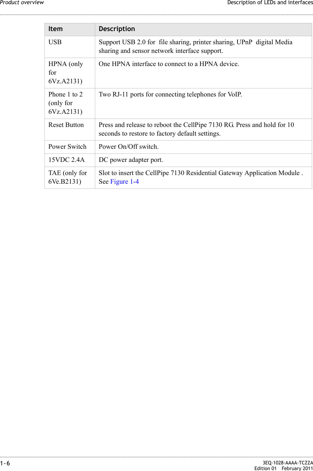
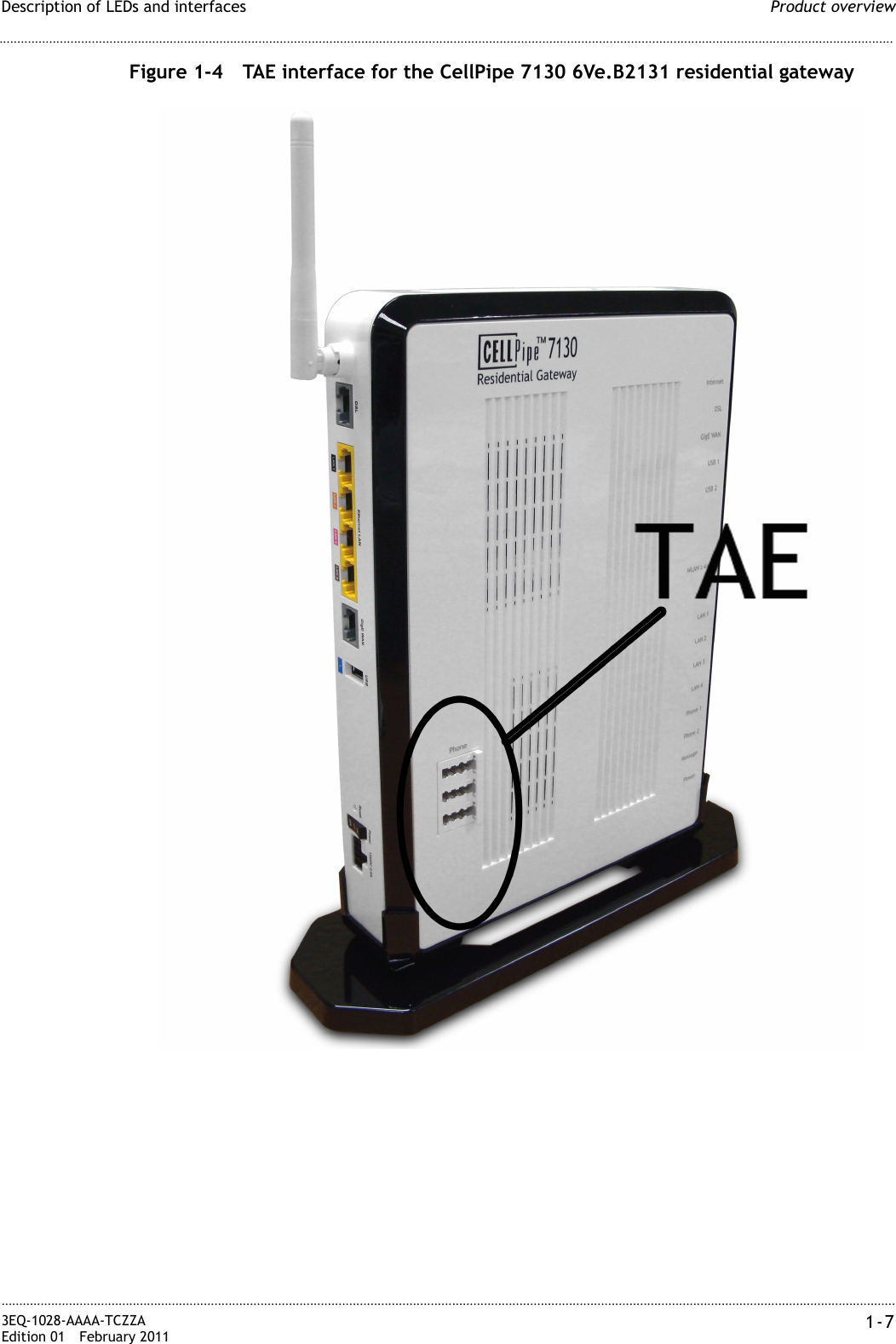
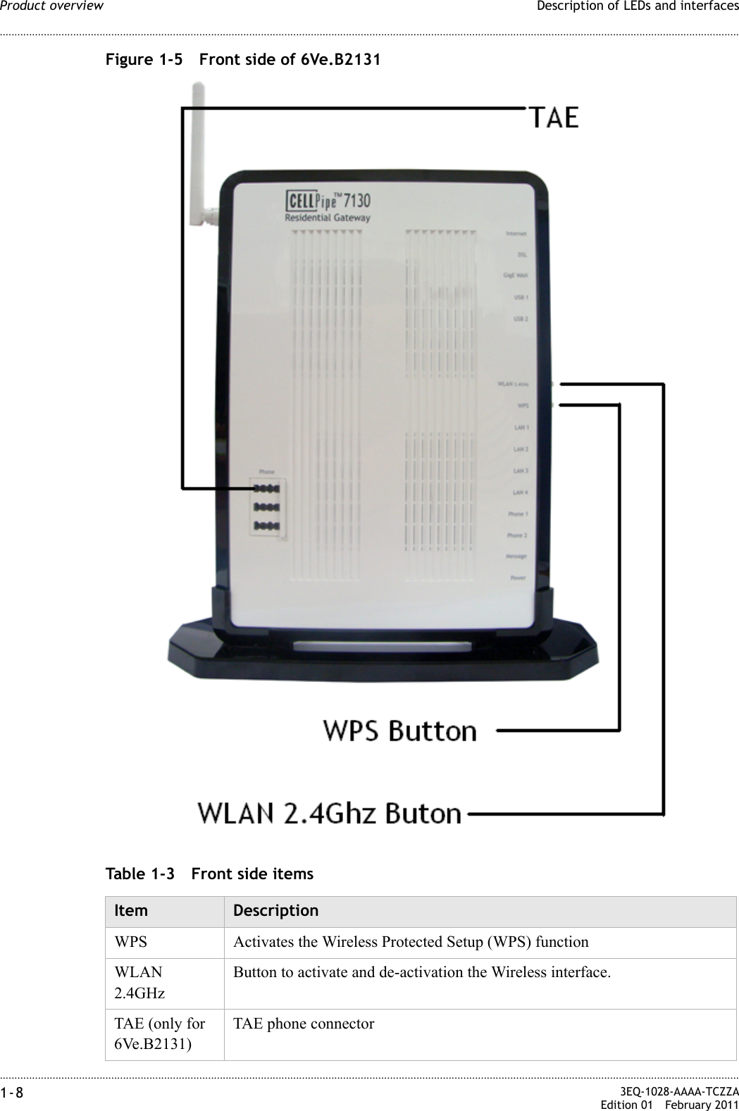


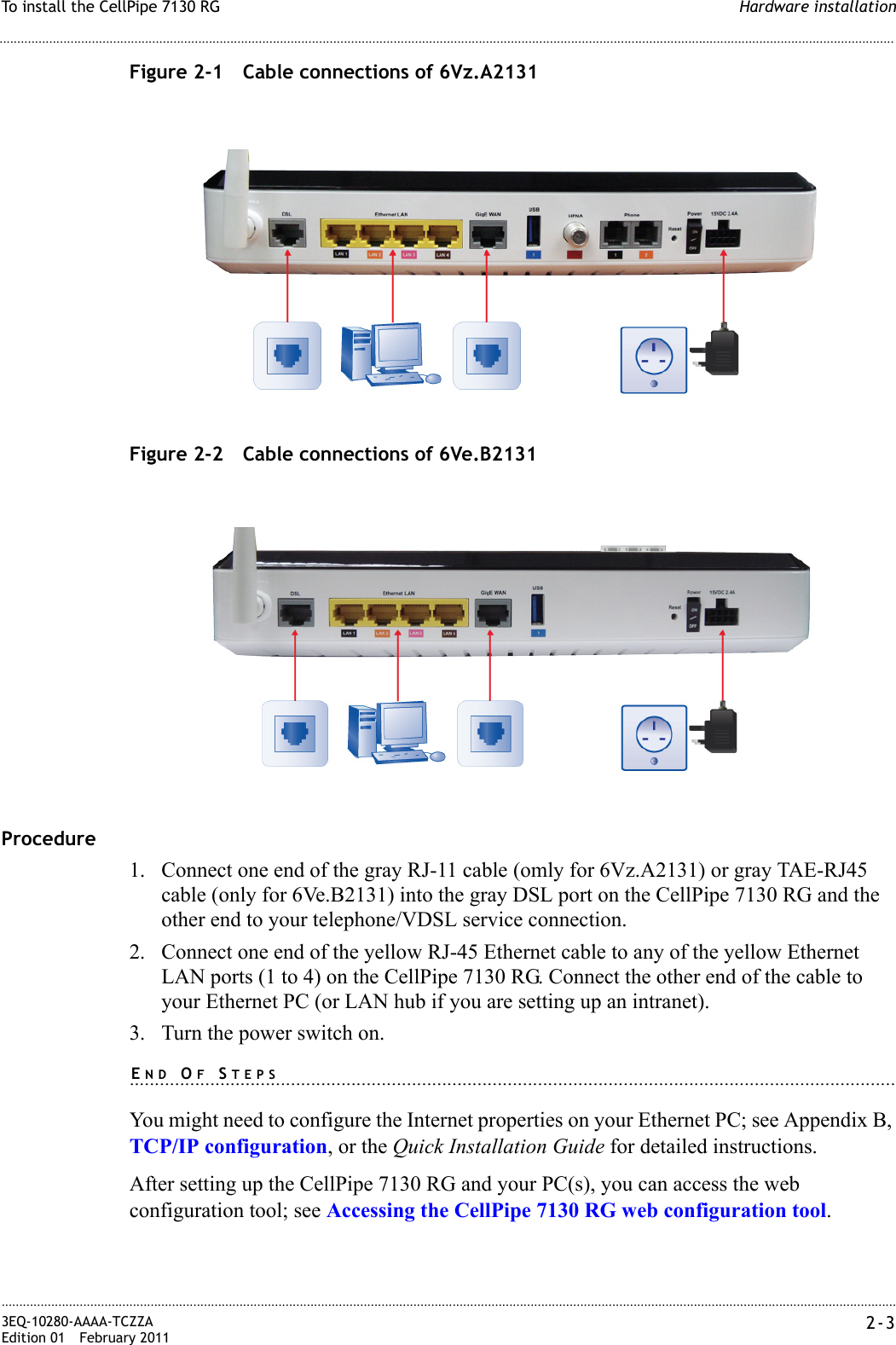
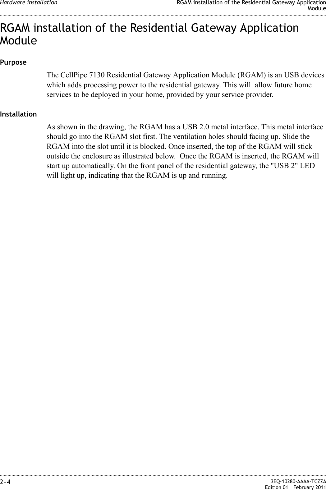
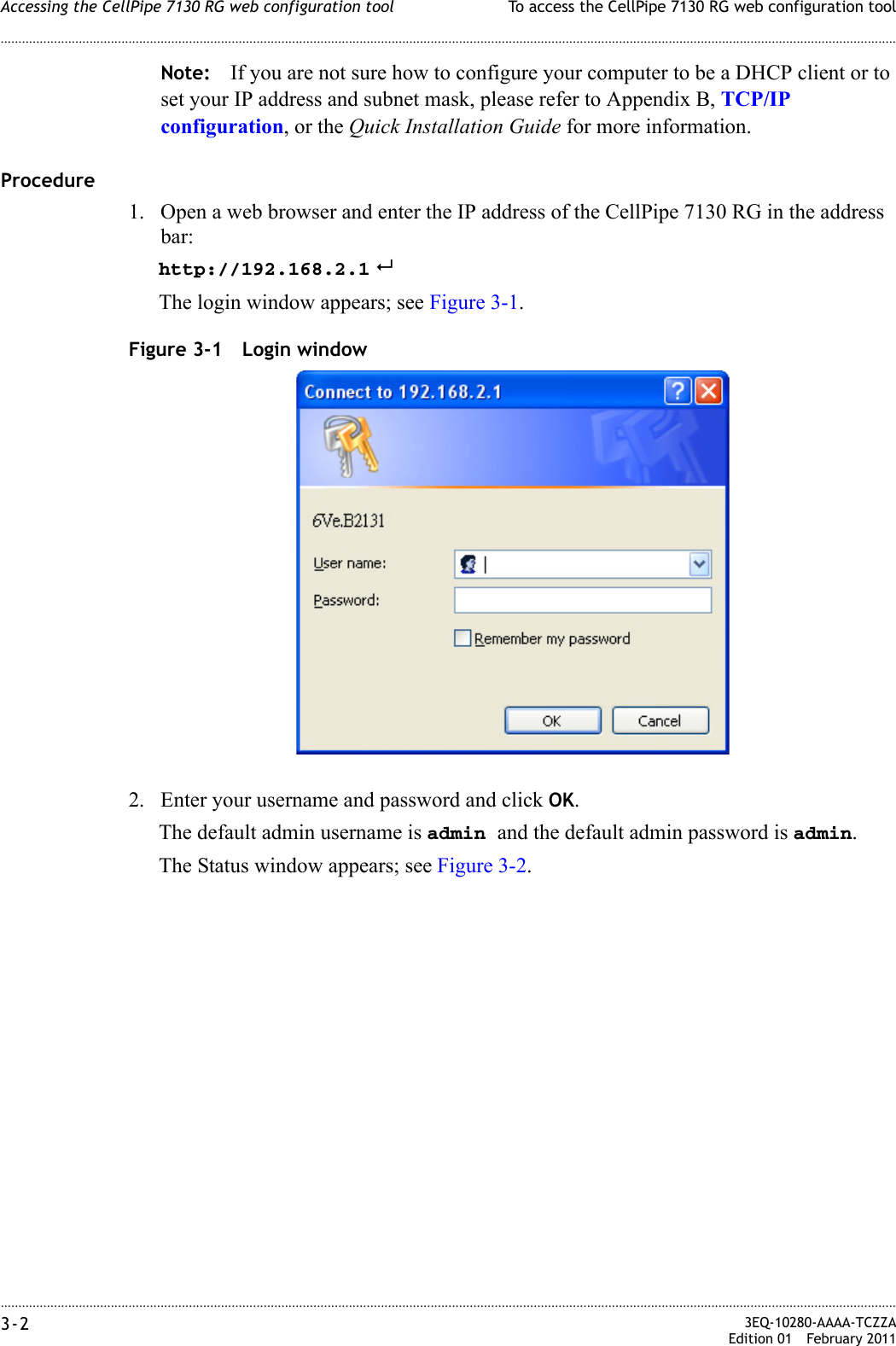
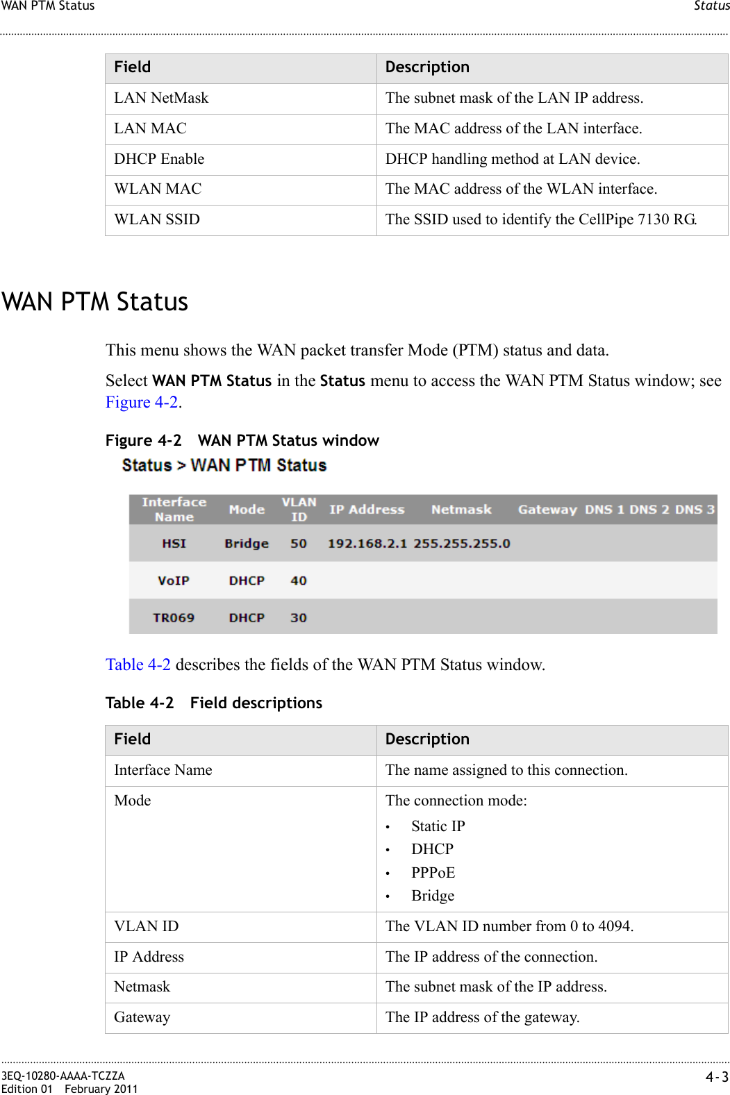
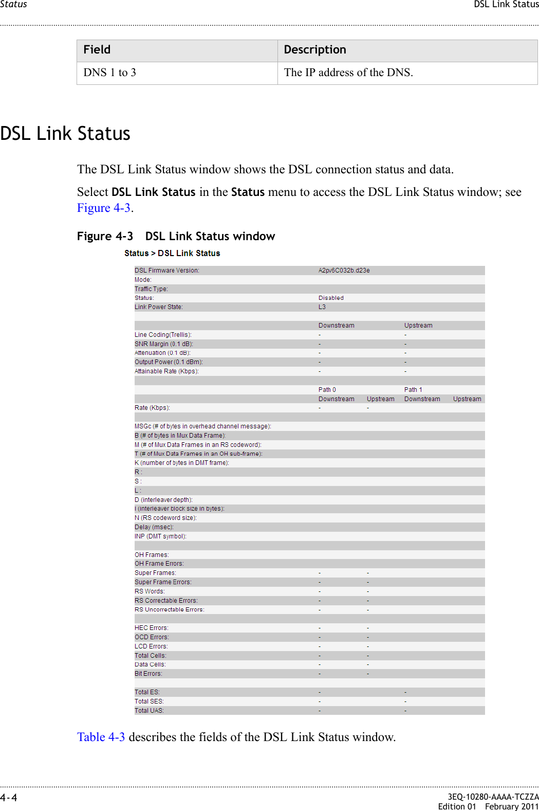
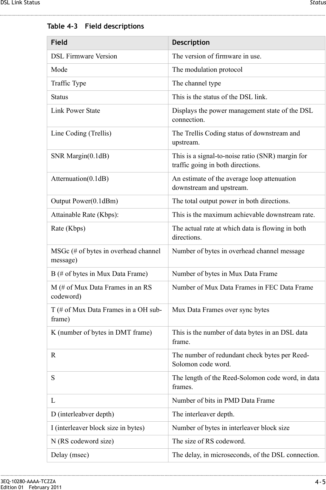
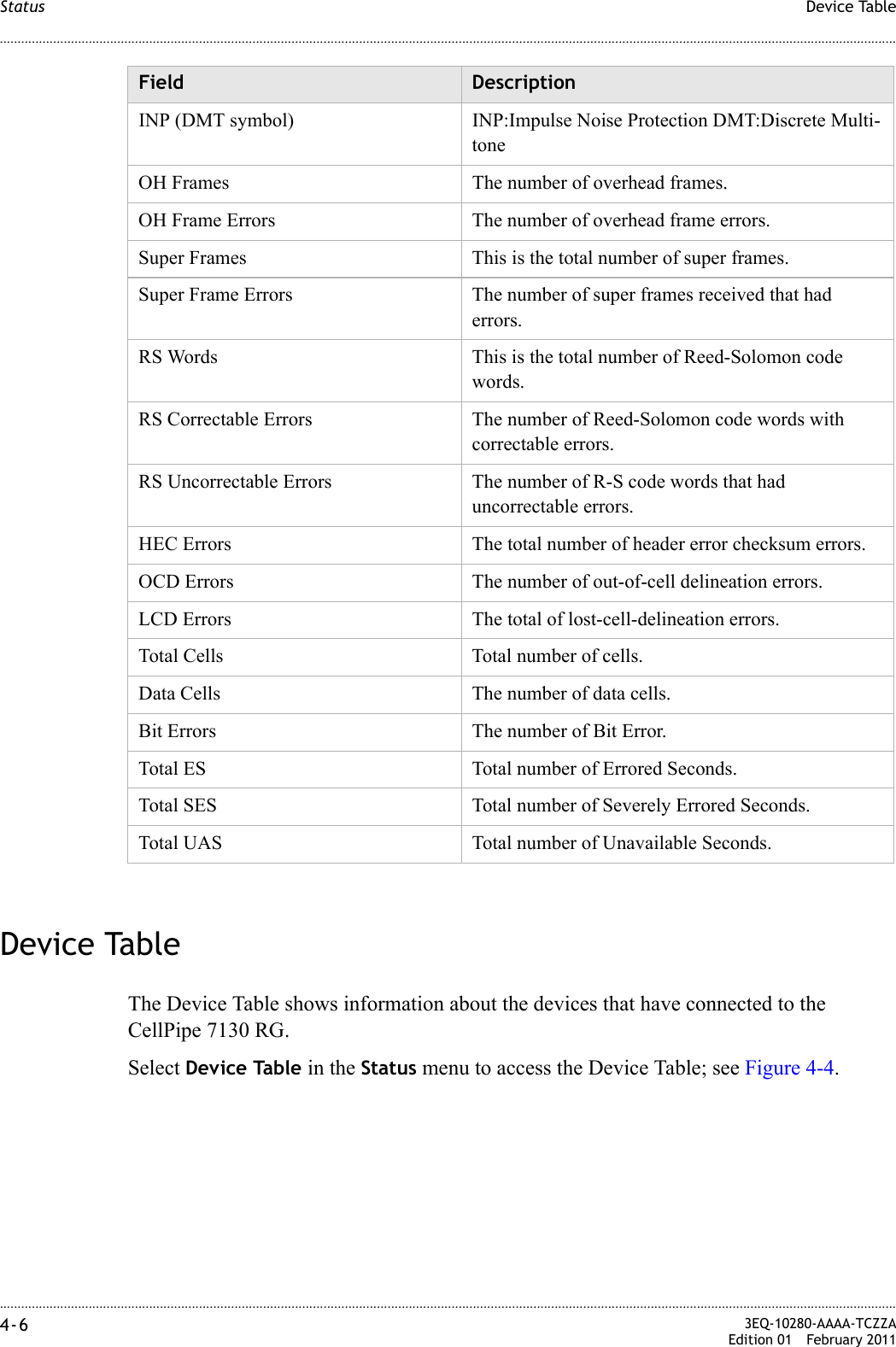
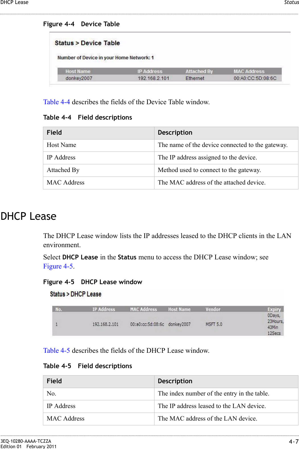
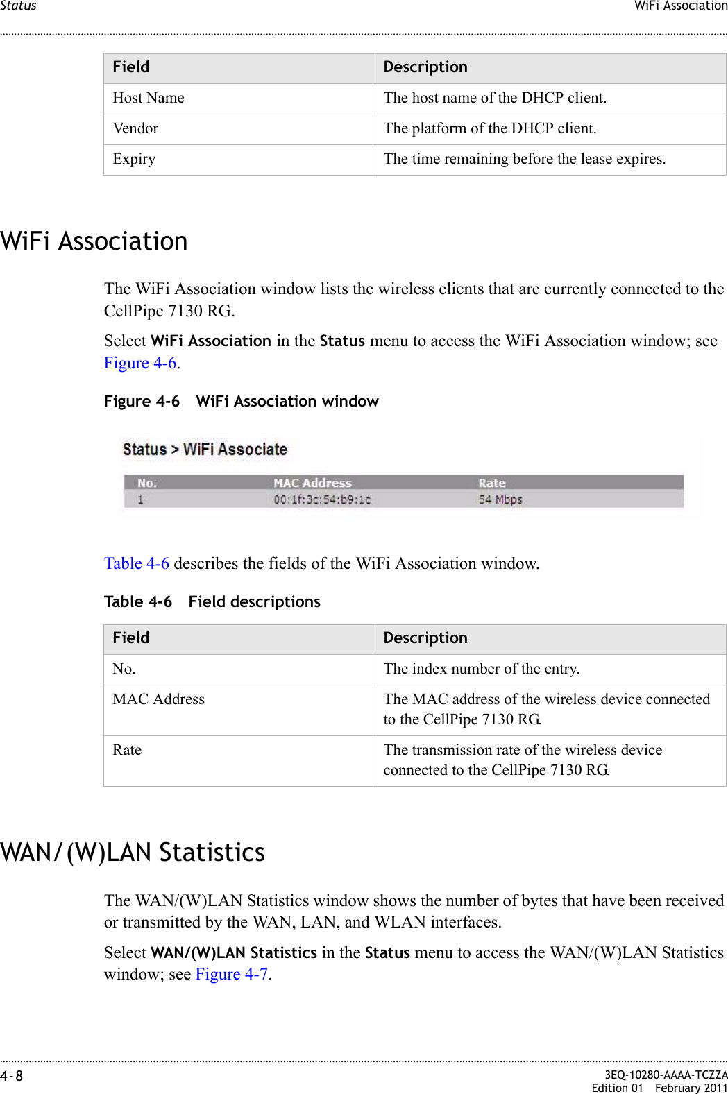
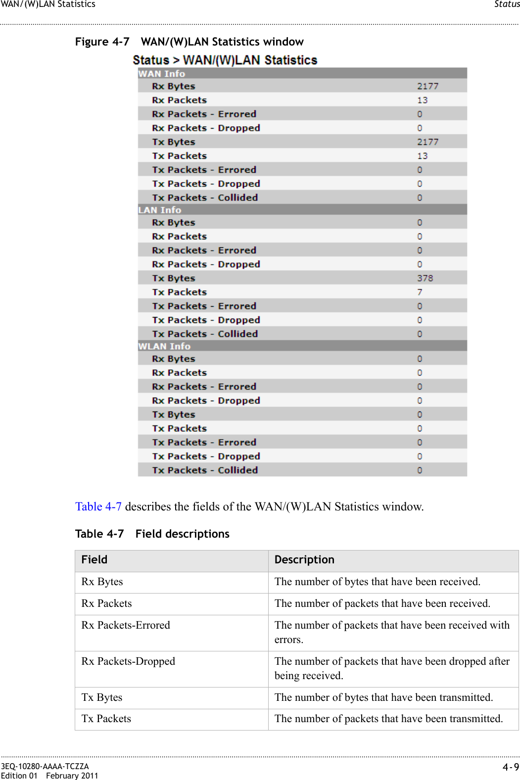
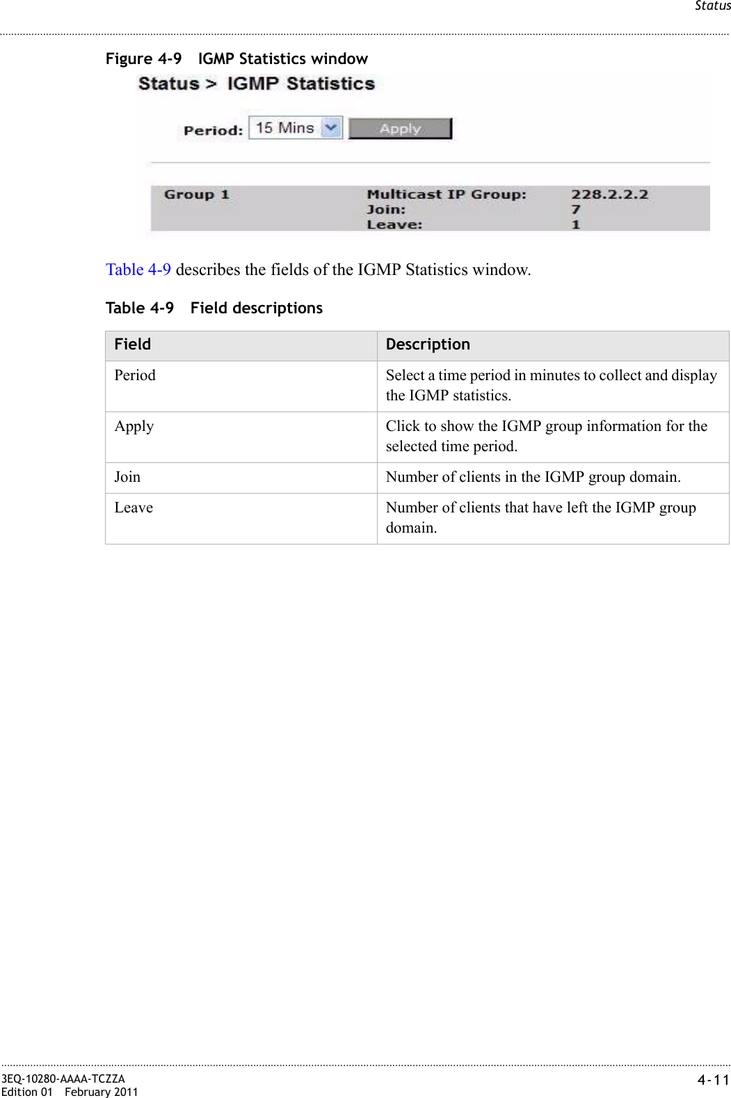
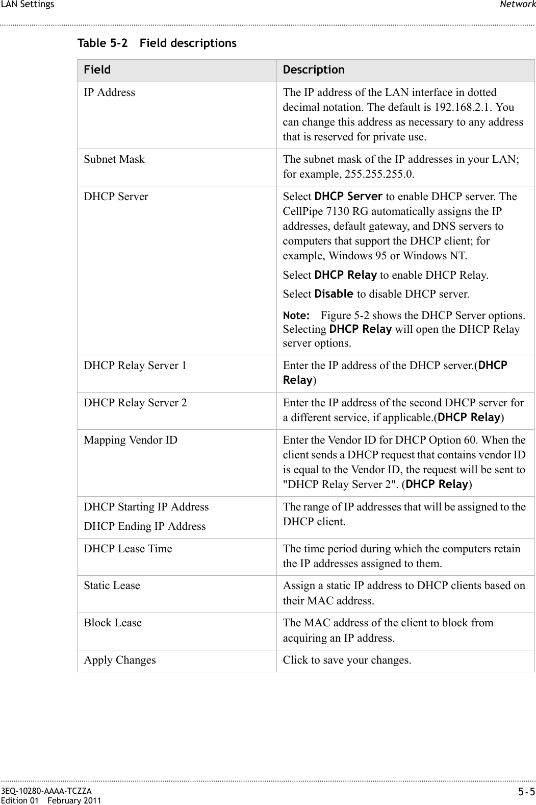
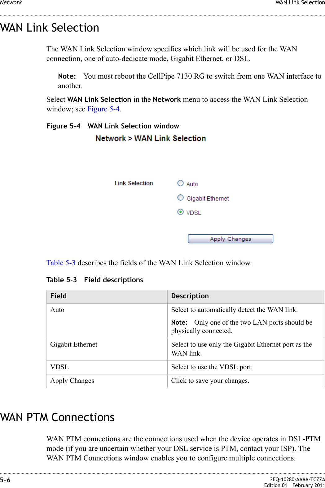
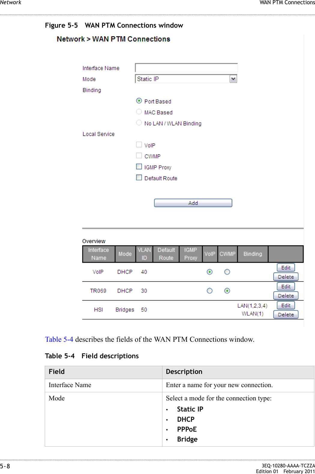
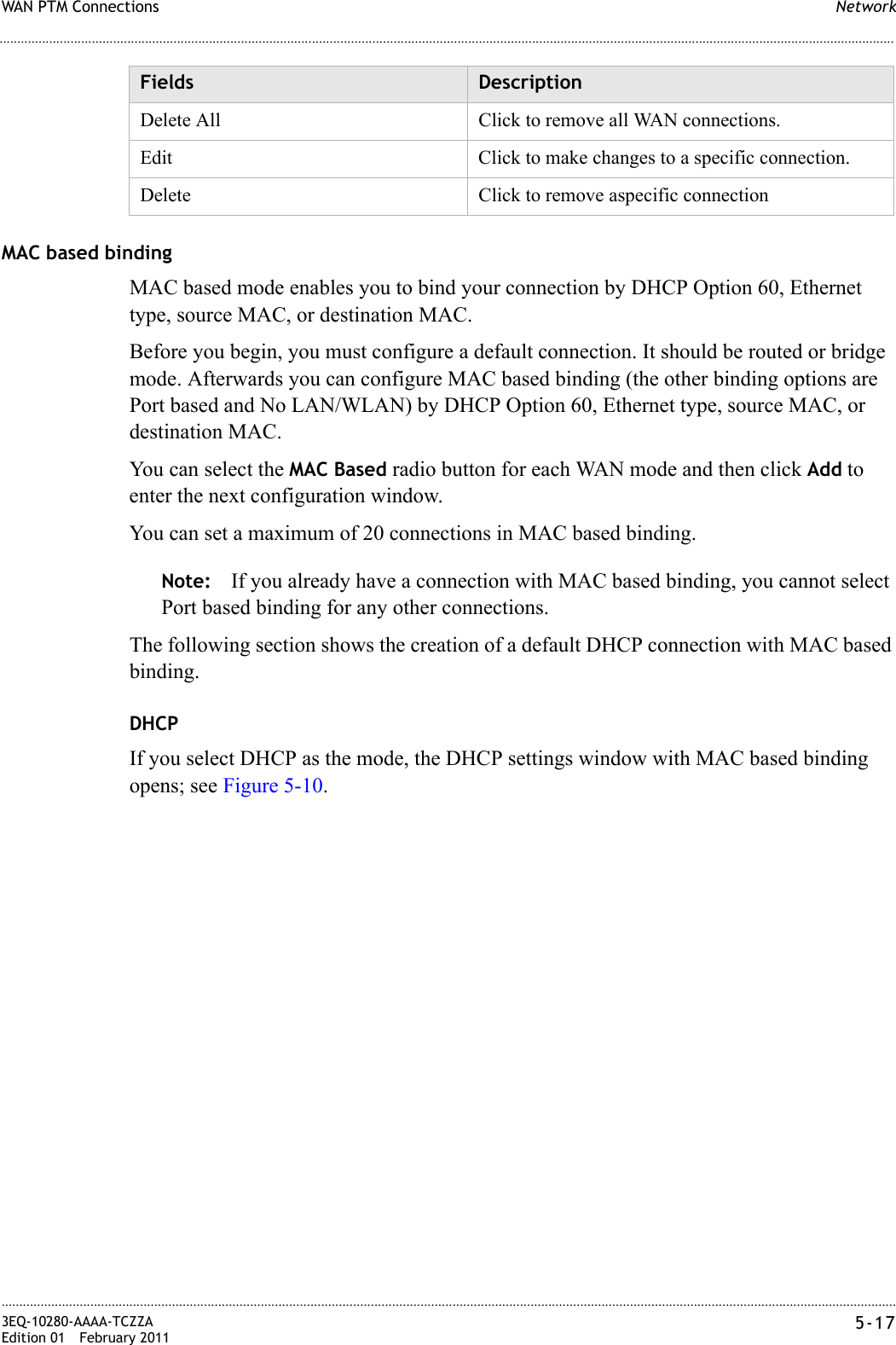
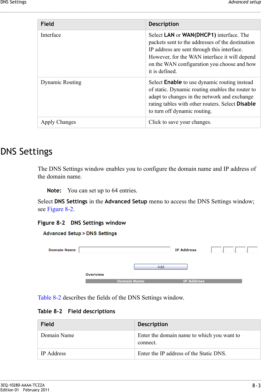
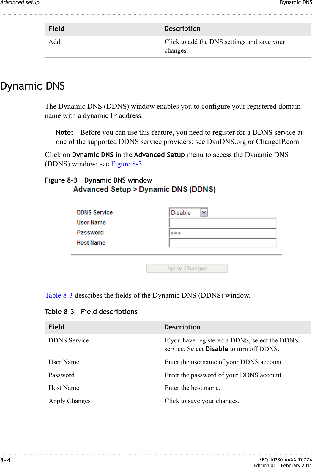
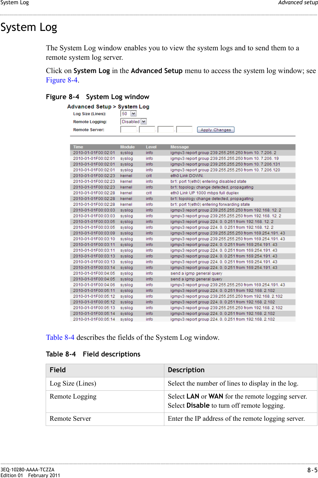
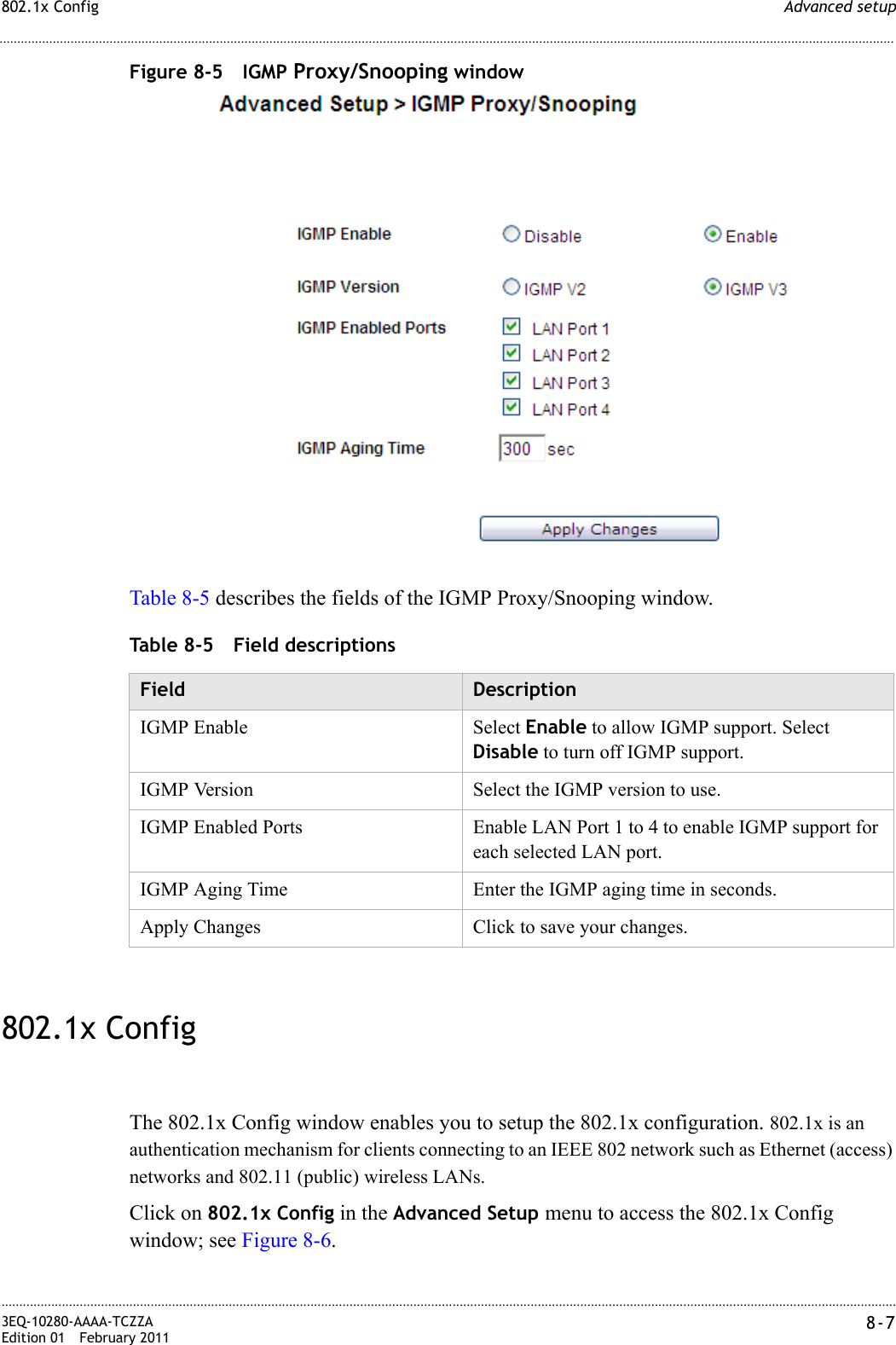
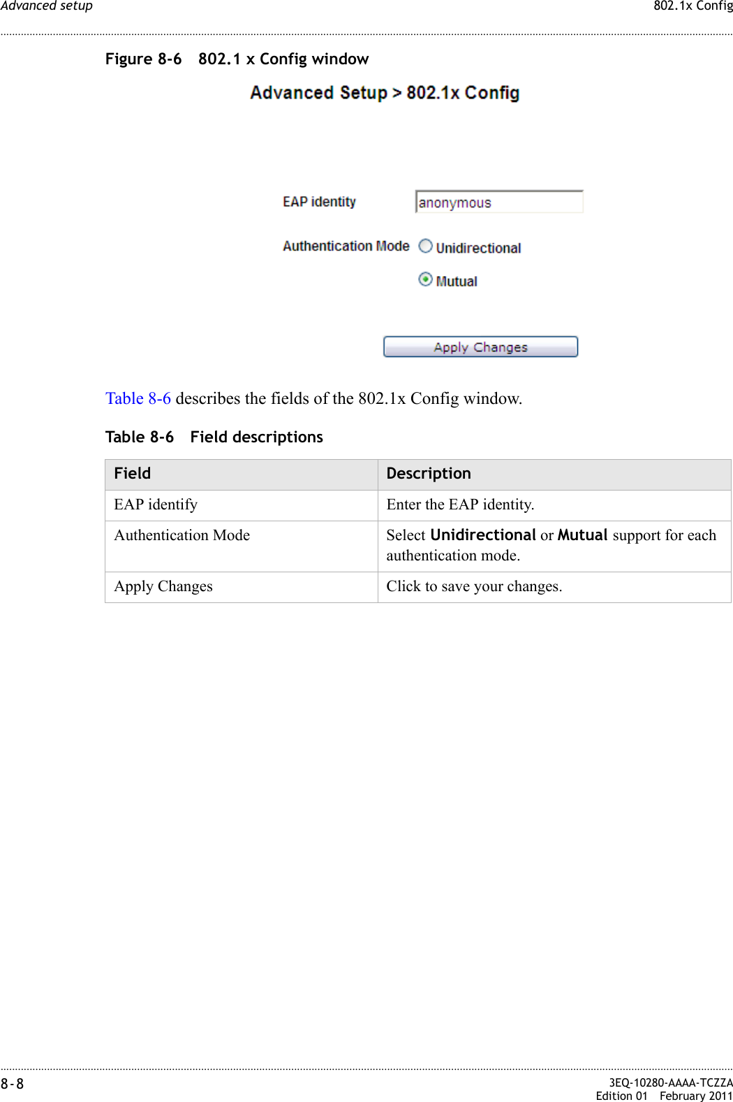
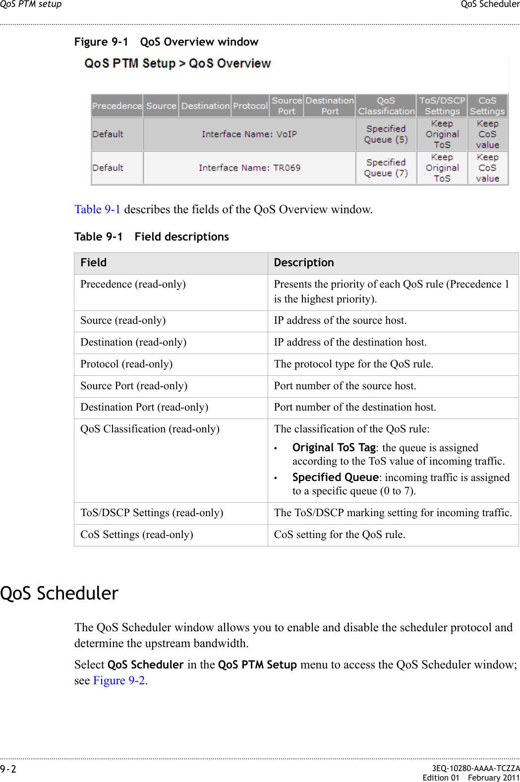
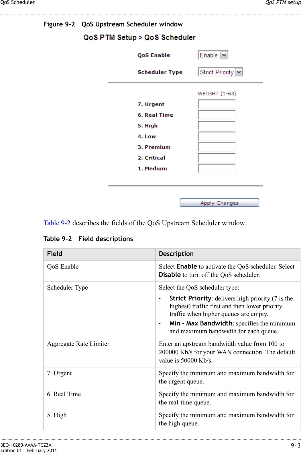
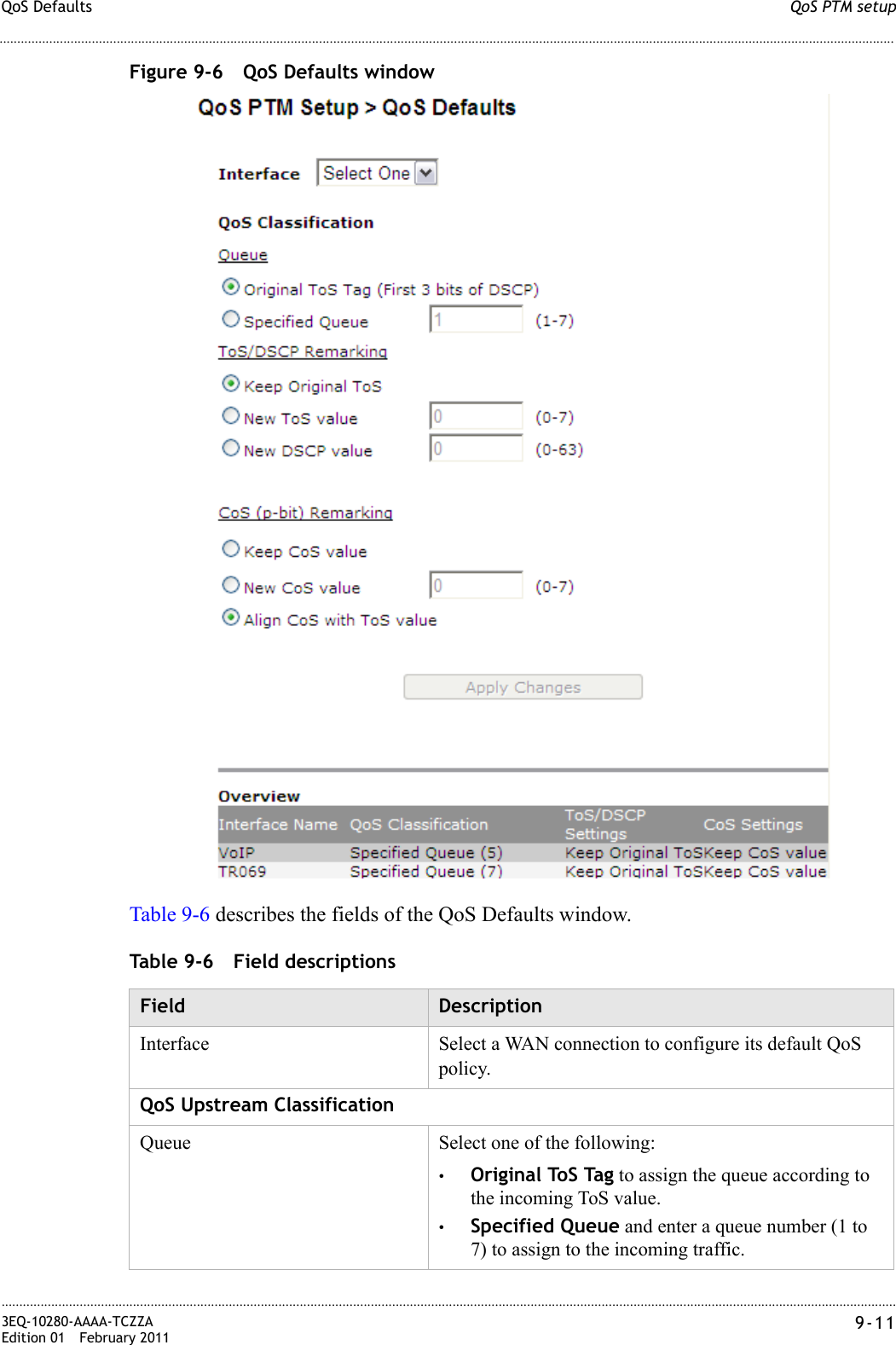
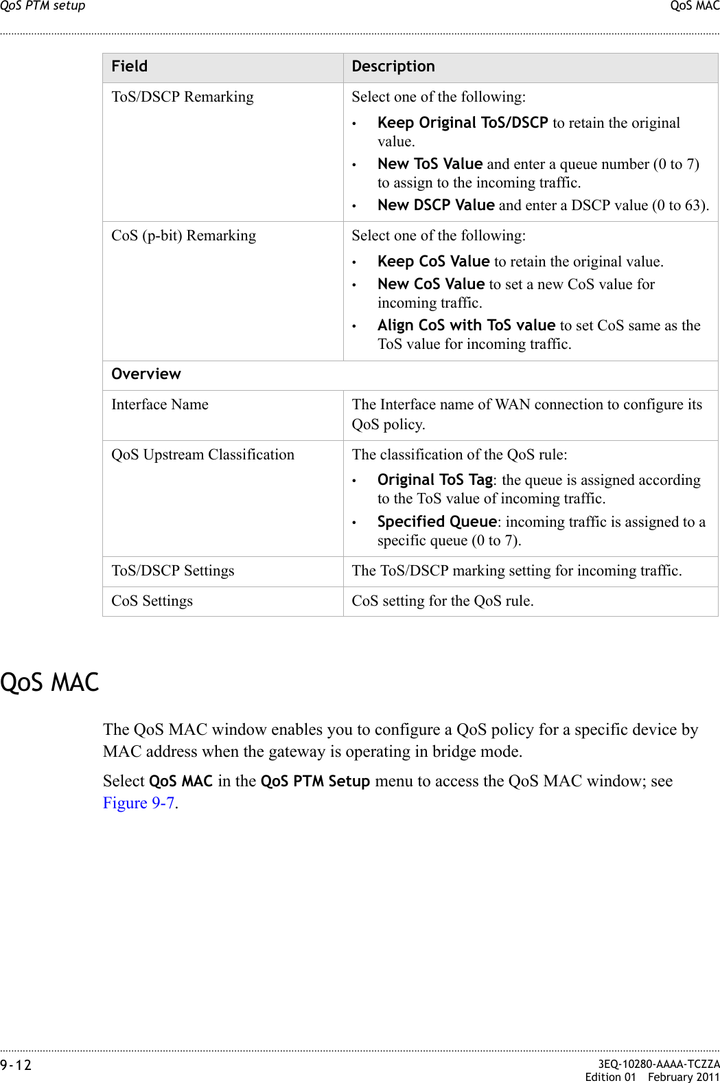
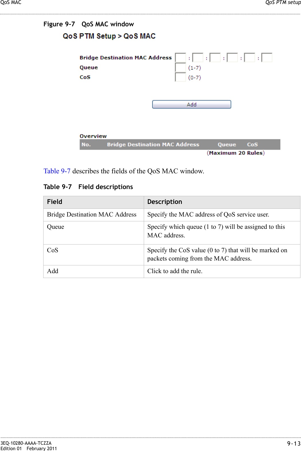
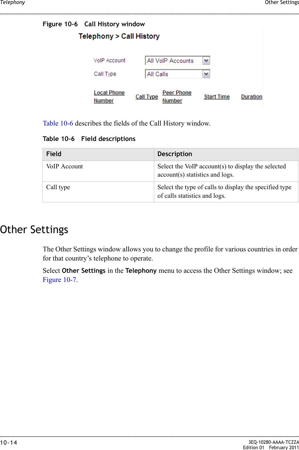
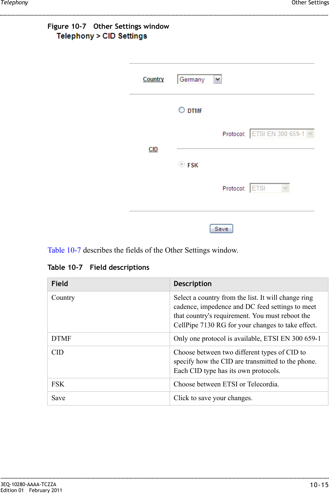
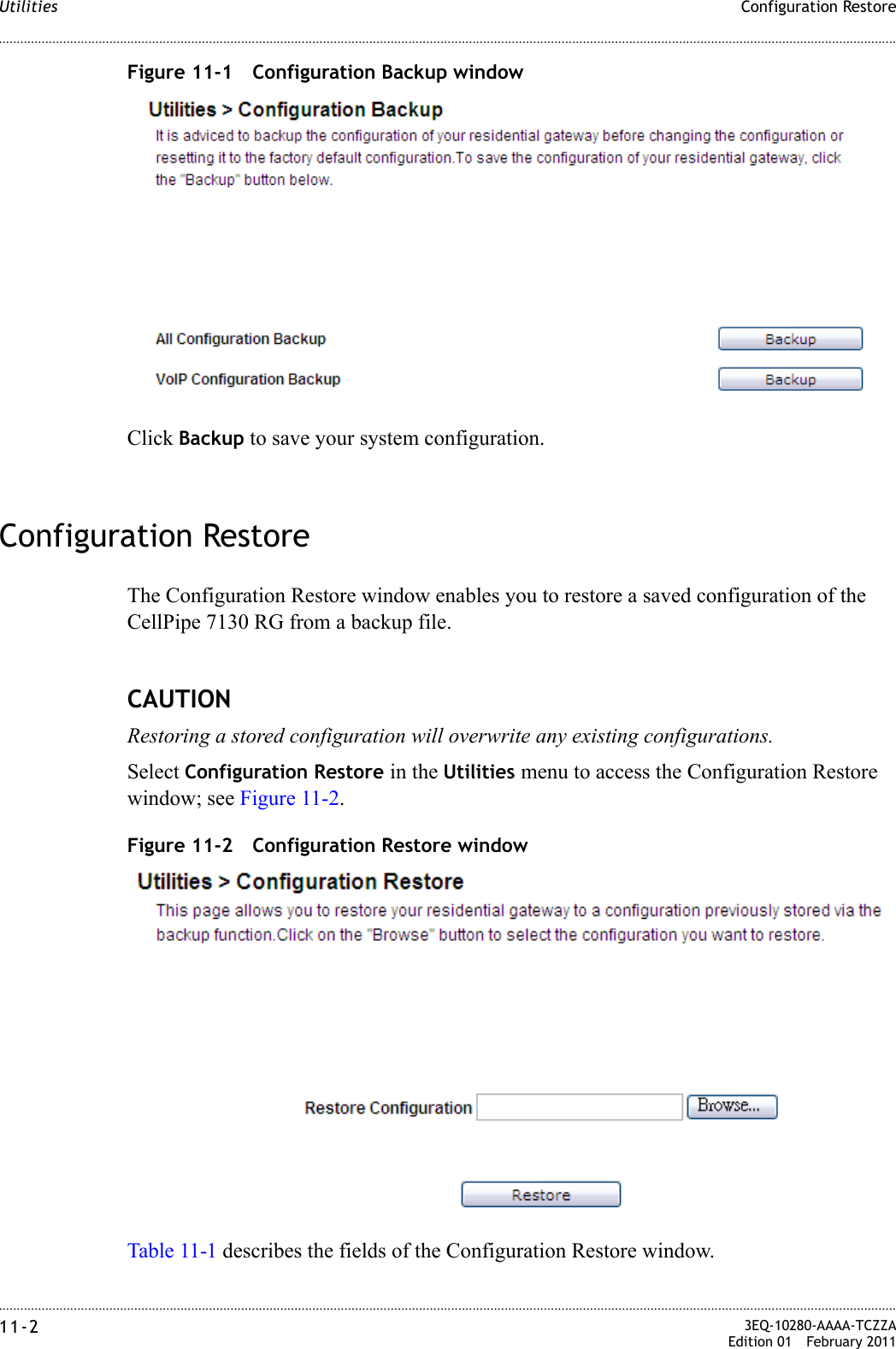
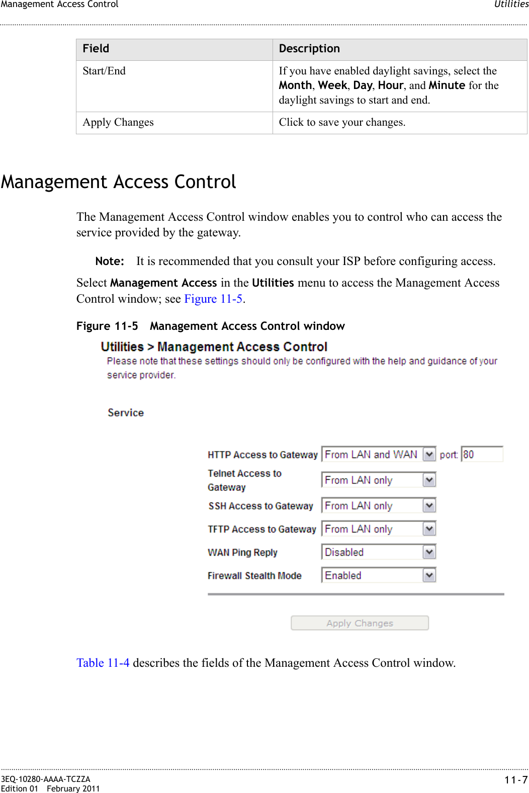
![............................................................................................................................................................................................................................................................To install the CellPipe 7130 RGHardware installation2-2 3EQ-10280-AAAA-TCZZAEdition 01 February 2011............................................................................................................................................................................................................................................................Important! Make sure that the screws are securely fixed to the wall and strong enough to hold the weight of the CellPipe 7130 RG (recommended screw type and size: Nylon wall plug [T8x25mm] and screws [T3.5x16mm]).2. Align the holes on the back of the CellPipe 7130 RG with the screws on the wall and then hang the CellPipe 7130 RG on the screws.........................................................................................................................................................END OF STEPSDesktop mountingPlace the CellPipe 7130 RG with the rubber feet at the bottom on a flat and stable surface.Stand-up mountingSnap the cradle into the holes located on the side of the CellPipe 7130 RG and then place it on a desk so that LEDs are visible.To install the CellPipe 7130 RGSupplies•CellPipe 7130 RG•One RJ-11 telephone cable (only for 6Vz.A2131)•One TAE-F to RJ45 cable (only for 6Ve.B2131)•One RJ-45 category 5 Ethernet cable (yellow)•Power adapterBefore you beginCAUTIONPotential for equipment damage and personal harmBefore installing the CellPipe 7130 RG, ensure you have thoroughly read the Safety precautions and Prerequisites in chapter 1.Turn off all devices (computer, hub, CellPipe 7130 RG) before beginning this procedure.](https://usermanual.wiki/GemTek-Technology/WVVDB-101N/User-Guide-1569005-Page-22.png)