Generac Power Systems 0G6020 2.4GHz Wireless Transmitter User Manual 0G5812revA indd
Generac Power Systems 2.4GHz Wireless Transmitter 0G5812revA indd
Exhibit D Users Manual per 2 1033 b3
Generac
Wireless Display
System
Instruction Manual
Preliminary Proof #2
07/20/07
TABLE OF CONTENTS
SAFETY ...................................... Inside Front Cover
Read This Manual Thoroughly .....................IFC
Operation and Maintenance ............................ 3
How to Obtain Service ..................................... 3
INTRODUCTION .................................................... 3
BATTERY OPERATION .......................................... 3
INSTALLATION ...................................................... 4
THE COMMUNICATIONS LED ............................... 5
GENERATOR COMMUNICATIONS ......................... 5
THE DISPLAY ........................................................ 5
Contrast Adjustment ....................................... 5
Backlight ......................................................... 5
Buttons............................................................ 5
Battery and Signal Strength Indicators............ 5
ALARM AND STATUS DISPLAY ............................. 6
THE MENU SYSTEM ............................................. 6
Status Menu .................................................... 6
Test Menu ........................................................ 6
History Menu ................................................... 7
Email Menu ..................................................... 7
SETTINGS MENU .................................................. 7
Adjust Contrast ............................................... 7
VAC Threshold ................................................ 7
Service Schedule ............................................. 7
EXERCISE MENU .................................................. 7
RADIO MENU......................................................... 8
Radio information ........................................... 8
Changing Channels .......................................... 8
Reset Radio ..................................................... 8
Add New Display ............................................. 8
Test Radio Link ............................................... 9
TIME & DATE MENU ............................................. 9
GRAPH MENU ....................................................... 9
MENU MAP ............................................ Back Cover
SAFETY
This device complies with Part 15 of the FCC Rules.
Operation is subject to the following conditions:
This device may not cause harmful interference.
This device must accept any interference received,
including interference that may cause undesired
operation.
READ THIS MANUAL THOROUGHLY
If any portion of this manual is not understood, con-
tact the nearest Authorized Service Dealer for start-
ing, operating and servicing procedures.
Throughout this publication, and on tags and decals
affixed to the generator, DANGER, WARNING,
CAUTION and NOTE blocks are used to alert person-
nel to special instructions about a particular service
or operation that may be hazardous if performed
incorrectly or carelessly. Observe them carefully.
Their definitions are as follows:
DANGER
After this heading, read instructions that, if not
strictly complied with, will result in personal injury
or property damage.
After this heading, read instructions that, if not
strictly complied with, may result in personal inju-
ry or property damage.
After this heading, read instructions that, if not
strictly complied with, could result in damage to
equipment and/or property.
NOTE:
After this heading, read explanatory statements
that require special emphasis.
These safety warnings cannot eliminate the hazards
that they indicate. Common sense and strict compli-
ance with the special instructions while performing
the service are essential to preventing accidents.
Four commonly used safety symbols accompany the
DANGER, WARNING and CAUTION blocks. The type
of information each indicates is as follows:
This symbol points out important safety informa-
tion that, if not followed, could endanger personal
safety and/or property of others.
This symbol points out potential explosion hazard.
•
•
Table of Contents
Wireless Display System
1
This symbol points out potential fire hazard.
This symbol points out potential electrical shock
hazard.
Study these SAFETY RULES carefully before install-
ing, operating or servicing this equipment. Become
familiar with this Owner’s Manual and with the unit.
The generator can operate safely, efficiently and reli-
ably only if it is properly installed, operated and
maintained. Many accidents are caused by failing to
follow simple and fundamental rules or precautions.
The manufacturer cannot anticipate every possible
circumstance that might involve a hazard. The warn-
ings in this manual, and on tags and decals affixed
to the unit are, therefore, not all inclusive. If using a
procedure, work method or operating technique that
the manufacturer does not specifically recommend,
ensure that it is safe for all personnel. Also make sure
the procedure, work method or operating technique
utilized does not render the generator unsafe.
DANGER
Despite the safe design of this generator,
operating this equipment imprudently, neglect-
ing its maintenance or being careless can cause
possible injury or death. Permit only responsible
and capable persons to install, operate or main-
tain this equipment.
Potentially lethal voltages are generated by
these machines. Ensure all steps are taken to
render the machine safe before attempting to
work on the generator.
Parts of the generator are rotating and/or hot
during operation. Exercise care near running
generators.
GENERAL HAZARDS
For safety reasons, the manufacuter recommends
that this equipment be installed, serviced and
repaired by an Authorized Service Dealer or other
competent, qualified electrician or installation tech-
nician who is familiar with applicable codes, stan-
dards and regulations. The operator also must com-
ply with all such codes, standards and regulations.
Installation, operation, servicing and repair of this
(and related) equipment must always comply with
applicable codes, standards, laws and regulations.
Adhere strictly to local, state and national electri-
cal and building codes. Comply with regulations
the Occupational Safety and Health Administration
(OSHA) has established. Also, ensure that the
generator is installed, operated and serviced in
accordance with the manufacturer’s instructions
and recommendations. Following installation, do
nothing that might render the unit unsafe or in
noncompliance with the aforementioned codes,
standards, laws and regulations.
The engine exhaust fumes contain carbon monox-
ide gas, which can be DEADLY. This dangerous gas,
if breathed in sufficient concentrations, can cause
unconsciousness or even death. For that reason,
adequate ventilation must be provided. Exhaust
gases must be piped safely away from any building
or enclosure that houses the generator to an area
where people, animals, etc., will not be harmed.
This exhaust system must be installed properly,
in strict compliance with applicable codes and
standards.
Keep hands, feet, clothing, etc., away from drive
belts, fans, and other moving or hot parts. Never
remove any drive belt or fan guard while the unit
is operating.
Adequate, unobstructed flow of cooling and venti-
lating air is critical in any room or building hous-
ing the generator to prevent buildup of explosive
gases and to ensure correct generator operation.
Do not alter the installation or permit even partial
blockage of ventilation provisions, as this can seri-
ously affect safe operation of the generator.
Keep the area around the generator clean and
uncluttered. Remove any materials that could
become hazardous.
When working on this equipment, remain alert
at all times. Never work on the equipment when
physically or mentally fatigued.
•
•
•
•
•
•
•
The engine exhaust from this product
contains chemicals known to the state
of California to cause cancer, birth
defects or other reproductive harm.
•
WARNING:•
This product contains or emits chemicals
known to the state of California to cause
cancer, birth defects or other reproductive harm.
•
WARNING:•
SAVE THESE INSTRUCTIONS – The manufacturer suggests that these rules for safe
operation be copied and posted in potential hazard areas. Safety should be stressed to all
operators, potential operators, and service and repair technicians for this equipment.
SAVE THESE INSTRUCTIONS – This manual contains important instructions that should be
followed during installation and maintenance of the generator and batteries.

2
Wireless Display System
Inspect the generator regularly, and promptly
repair or replace all worn, damaged or defective
parts using only factory-approved parts.
Before performing any maintenance on the gen-
erator, disconnect its battery cables to prevent
accidental start-up. Disconnect the cable from the
battery post indicated by a NEGATIVE, NEG or (–)
first. Reconnect that cable last.
Never use the generator or any of its parts as a
step. Stepping on the unit can stress and break
parts, and may result in dangerous operating con-
ditions from leaking exhaust gases, fuel leakage,
oil leakage, etc.
ELECTRICAL HAZARDS
All generators covered by this manual produce
dangerous electrical voltages and can cause fatal
electrical shock. Utility power delivers extremely
high and dangerous voltages to the transfer switch,
as does the standby generator. Avoid contact with
bare wires, terminals, connections, etc., on the gen-
erator as well as the transfer switch, if applicable.
Ensure all appropriate covers, guards and barriers
are in place before operating the generator. If work
must be done around an operating unit, stand on
an insulated, dry surface to reduce shock hazard.
Do not handle any kind of electrical device while
standing in water, while barefoot, or while hands
or feet are wet. DANGEROUS ELECTRICAL
SHOCK MAY RESULT.
If people must stand on metal or concrete while
installing, operating, servicing, adjusting or repair-
ing this equipment, place insulative mats over a
dry wooden platform. Work on the equipment only
while standing on such insulative mats.
The National Electrical Code (NEC), Article 250
requires the frame and external electrically con-
ductive parts of the generator to be connected to
an approved earth ground and/or grounding rods.
This grounding will help prevent dangerous electri-
cal shock that might be caused by a ground fault
condition in the generator set or by static electric-
ity. Never disconnect the ground wire.
Wire gauge sizes of electrical wiring, cables and
cord sets must be adequate to handle the maxi-
mum electrical current (ampacity) to which they
will be subjected.
Before installing or servicing this (and related)
equipment, make sure that all power voltage
supplies are positively turned off at their source.
Failure to do so will result in hazardous and pos-
sibly fatal electrical shock.
Connecting this unit to an electrical system nor-
mally supplied by an electric utility shall be by
means of a transfer switch so as to isolate the
generator electric system from the electric utility
distribution system when the generator is operat-
ing. Failure to isolate the two electric system power
sources from each other by such means, will result
in damage to the generator and may also result
in injury or death to utility power workers due to
backfeed of electrical energy.
•
•
•
•
•
•
•
•
•
•
Generators installed with an automatic transfer
switch will crank and start automatically when
normal (UTILITY) source voltage is removed or is
below an acceptable preset level. To prevent such
automatic start-up and possible injury to person-
nel, disable the generator’s automatic start circuit
(battery cables, etc.) before working on or around
the unit. Then, place a “Do Not Operate” tag on
the generator control panel and on the transfer
switch.
In case of accident caused by electric shock, imme-
diately shut down the source of electrical power. If
this is not possible, attempt to free the victim from
the live conductor. AVOID DIRECT CONTACT
WITH THE VICTIM. Use a nonconducting imple-
ment, such as a dry rope or board, to free the
victim from the live conductor. If the victim is
unconscious, apply first aid and get immediate
medical help.
Never wear jewelry when working on this equip-
ment. Jewelry can conduct electricity resulting in
electric shock, or may get caught in moving com-
ponents causing injury.
FIRE HAZARDS
Keep a fire extinguisher near the generator at all
times. Do NOT use any carbon tetra-chloride type
extinguisher. Its fumes are toxic, and the liquid
can deteriorate wiring insulation. Keep the extin-
guisher properly charged and be familiar with its
use. If there are any questions pertaining to fire
extinguishers, consult the local fire department.
EXPLOSION HAZARDS
Properly ventilate any room or building housing
the generator to prevent build-up of explosive gas.
Do not smoke around the generator. Wipe up any
fuel or oil spills immediately. Ensure that no com-
bustible materials are left in the generator com-
partment, or on or near the generator, as FIRE or
EXPLOSION may result. Keep the area surround-
ing the generator clean and free from debris.
These generator sets may operate using one of
several types of fuels. All fuel types are potentially
FLAMMABLE and/or EXPLOSIVE and should be
handled with care. Comply with all laws regulat-
ing the storage and handling of fuels. Inspect the
unit’s fuel system frequently and correct any leaks
immediately. Fuel supply lines must be prop-
erly installed, purged and leak tested according to
applicable fuel-gas codes before placing this equip-
ment into service.
Diesel fuels are highly FLAMMABLE. Gaseous
fluids such as natural gas and liquid propane
(LP) gas are extremely EXPLOSIVE. Natural gas
is lighter than air, and LP gas is heavier than air;
install leak detectors accordingly.
•
•
•
•
•
•
•
•

3
OPERATION AND MAINTENANCE
The operator is responsible for proper and safe use
of the equipment. The manufacturer strongly recom-
mends that the operator read this Owner's Manual
and thoroughly understand all instructions before
using this equipment. The manufacturer also strong-
ly recommends instructing other users to properly
start and operate the unit. This prepares them if they
need to operate the equipment in an emergency.
It is the operator's responsibility to perform all safety
checks, to make sure that all maintenance for safe
operation is performed promptly, and to have the
equipment checked periodically by an Authorized
Service Dealer. Normal maintenance service and
replacement of parts are the responsibility of the
owner/operator and, as such, are not considered
defects in materials or workmanship within the
terms of the warranty. Individual operating habits
and usage contribute to the need for maintenance
service.
Proper maintenance and care of the generator ensures
a minimum number of problems and keeps operating
expenses at a minimum. See an Authorized Service
Dealer for service aids and accessories.
Operating instructions presented in this manual
assume that the standby electric system has been
installed by an Authorized Service Dealer or other
competent, qualified contractor. Installation of this
equipment is not a “do-it-yourself” project.
HOW TO OBTAIN SERVICE
When the generator requires servicing or repairs,
contact an Authorized Service Dealer for assistance.
Service technicians are factory-trained and are capa-
ble of handling all service needs.
When contacting an Authorized Service Dealer about
parts and service, always supply the complete model
number of the unit as given on the front cover of this
manual or on the DATA LABEL affixed to the unit.
INTRODUCTION
The wireless display system consists of two identical
radio transceivers, one mounted near the generator
and the other (the one with the display), should be
in a convenient viewing location. The system has a
“line of sight” range of about 300 feet but this will be
reduced if the signal has to go through walls, etc.. The
display is intended to show the status of the genera-
tor and warn you if the system is in an alarm state. It
also provides the following additional functions:
Permanent time/date stamped history of generator
events such as starting and stopping
Allowing remote starting and stopping of the gen-
erator
•
•
Facility to set an exercise time & day from the dis-
play
Facility to adjust the “bad” utility voltage thresh-
old
Facility to set up a service schedule
Ability to add extra displays
Graphing capability
The unit can be either battery powered or fed from a
separate plug in wall transformer. The History is kept
in permanent memory that is not lost even when all
power is lost. The clock function is kept alive by a
separate, replaceable 10 year life battery.
BATTERY OPERATION
The wireless display can be operated either from a
plug in wall transformer or from three AAA alkaline
batteries. The batteries can be rechargeable but are
NOT recharged from the wall transformer and should
be separately charged. In the case of battery opera-
tion, the unit will go to sleep for 60 seconds then
exchange data for up to two (2) seconds to conserve
battery life. The display screen will turn off in the
sleep mode unless there is an alarm to be displayed.
It can be awoken by pressing the ENTER key after
which it will remain awake for one (1) minute if no
further keys are pressed. If the display is operated
continuously on batteries, the expected battery life is
three (3) months when using standard alkaline 1.2Ah
batteries. The batteries are NOT used to retain data
such as the history log or the radio settings, they will
not be lost in the event of a dead battery.
NOTE 1:
In battery sleep mode it will take up to two (2)
minutes to detect if the radio link is lost. This long
delay is to allow for the unit’s sleep time.
NOTE 2:
In battery sleep mode, if the wall transformer is
plugged into the unit, it will take up to one minute
to recognize this fact.
There is a separate battery for the time and date
function. This has an expected life of ten years
after which it can be replaced. To replace the bat-
tery, remove the four screws holding on the back
of the case and carefully fold out the circuit board
without disconnecting the display. Remove the large
yellow battery module from the centre of the board
by pulling on the corners. Replace the battery THE
CORRECT WAY ROUND with the spot in the corner
of the battery facing the on/off switch. Replace the cir-
cuit board and the back of the case. You will need to
reset the time and date. The GENERAC part number
for the battery is 0A7287G.
•
•
•
•
•
Wireless Display System
4
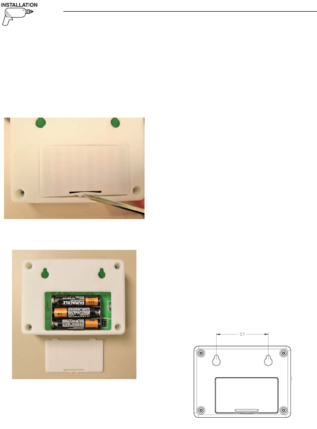
INSTALLATION
For easier installation, the batteries should first be
fitted into the display unit (Figure 1). This will allow
you to walk around and find the best location for the
unit while still receiving good signal strength. Attach
the other transceiver to the generator and mount it as
high as possible, preferably away from any structures
to get a maximum signal.
Figure 1 — Open Display Unit
1. Insert the batteries (Figure 2).
Figure 2 — Insert Batteries
2. Connect the generator end transceiver and ensure
it is turned on.
3. IMMEDIATELY turn on the display, one minute
will pass while the generator tries to find it’s dis-
play.
4. The display will show that it is searching for the
generator and the yellow LED may flash occasion-
ally as it receives data from the generator trans-
ceiver. This is due to the unit searching for the
correct channel.
5. Once the generator is found, the radio link is now
setup and the settings will be remembered next
time the display unit is turned on. If the genera-
tor is not found, an error message will briefly be
shown, and the yellow LED will flash at one (1)
second intervals to indicate the display unit was
unable to find the generator.
6. If the battery power to the generator (and there-
fore the end transceiver) is ever disconnected, the
radio link will need to be reset. See the section
titled “Reset Radio”.
7. If the generator is not talking to it’s transceiver,
but the radios are talking to each other, this will
be indicated by an appropriate alarm which will
be displayed after a 30 second period. Check the
wiring and connection to the generator.
8. Place the display at the preferred location. Do not
permanently mount it yet.
9. Plug the wall transformer into the display so as
not to use up the batteries. Familiarize personnel
with the radio menu (by reading the manual in
conjunction with operating the display).
10. Navigate the display to show the “Radio
Information” screen from the radio menu.
11. Monitor the signal strength and relocate the dis-
play if the signal strength is poor or non existent.
The signal strength display is only updated if the
unit can communicate, (which occurs every two
(2) seconds), and will be set to display zero if the
unit cannot communicate within a ten (10) sec-
ond period.
12. Mount the display using the holes on the back to
hang onto two suitably sized fixing screws in the
drywall 2¼ inches apart. It should be vertically
mounted on a wall BETWEEN studs for maxi-
mum signal strength (Figure 3).
Figure 3 — Mounting Holes
Wireless Display System
5
Wireless Display System
13. Set the time and date into the clock, use the
instructions given in the "Time and Date Menu"
section. The time & date will be remembered
even if the battery goes dead. There is a separate,
replaceable 10 year battery for this function.
14. The communications LED will light solid to show
data is being received. A flashing LED indicates
the unit was unable to find the generator.
15. Set an exercise day and time now (see "Exercise
Menu" section).
THE COMMUNICATIONS LED
The communications LED will light solid to show
data is being received. If the LED flashes at regular
one (1) second intervals, it indicates the unit was
unable to find the generator. Irregular flashing is an
indication of poor reception.
GENERATOR COMMUNICATIONS
The transceiver requests data from the generator
every two (2) seconds and this is stored inside the
transceiver locally. The data is relayed to the base
station over the radio link every time it is requested
by the display about every two (2) seconds. When
on battery power, the data is only requested every
minute to conserve batteries. If the generator is not
talking to it’s transceiver, but the radios are talking
to each other, this will be indicated by an appropri-
ate alarm which will be displayed after a seven (7)
second period (Figure 4). Check the wiring and con-
nection to the generator.
Figure 4 — Sample Alarm
WARNING
RADIO OK
BUT GEN
IS NOT
TALKING
THE DISPLAY
CONTRAST ADJUSTMENT
The display contrast can be adjusted from the
“Settings” menu. Any changes to the contrast setting
will be remembered even if power is removed from
the display.
BACKLIGHT
The display is backlit providing that it is powered
from the wall transformer. If batteries are being
used the backlight is disabled to conserve power.
The backlight is lit whenever a key is pressed. It will
remain lit for 20 seconds if there are no further key-
presses. If an alarm occurs, the backlight will flash at
a one (1) second rate (not if battery powered).
BUTTONS
Operation of the display is controlled by three (3)
buttons labeled +, —, and Enter. These buttons are
used to navigate the display to the required page, or
to enter data. The +/— buttons are also referred to
as the arrow keys. Holding down a button for more
than half a second will cause it to autorepeat until it
is released.
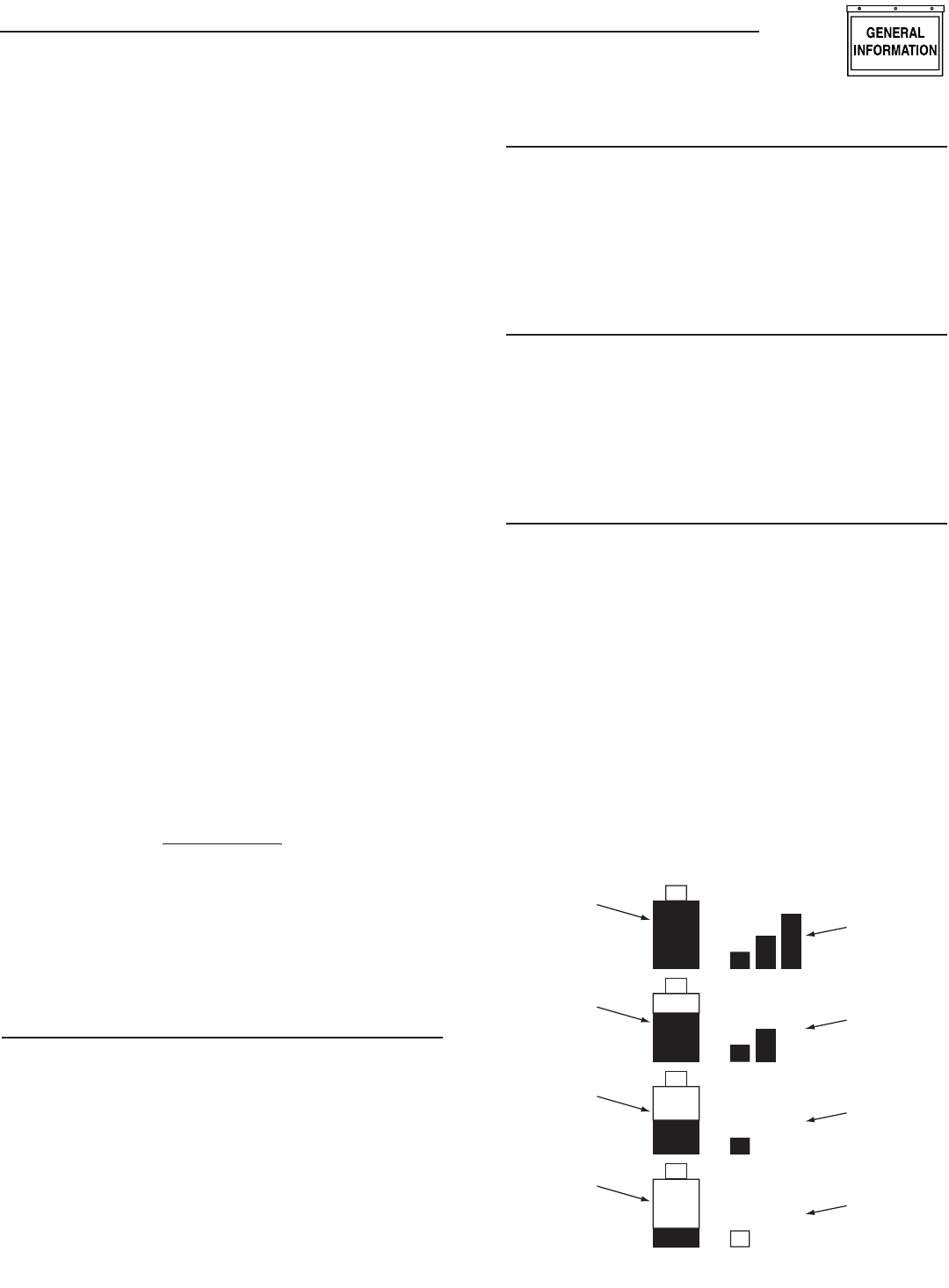
BATTERY AND SIGNAL STRENGTH INDICATORS
In the top left corner of the display, there are two
icons (or pictures) that give a quick indication of
the state of the internal battery and the radio signal
strength (Figure 5). The battery is represented by the
left hand, single tall rectangle which is drawn as being
somewhere between full and empty. Full represents
greater than 75% capacity, mostly full represents 50-
75% capacity, half full represent 25-50% and mostly
empty represents 0-25% capacity. The signal strength
icon is shown to the right of the battery icon as three
vertical bars representing greater than 25%, greater
than 50%, and greater than 75%. Three bars indicate
excellent signal strength, two bars represent good
signal strength (about 45%), one bar represents weak
signal strength. Two bars is the normal indication.
Figure 5 — Battery & Signal Strength
Signal
Strength
Is Excellent
Battery
has more
than 75%
Capacity
Battery
has 50-75%
Capacity
Battery
has 25-50%
Capacity
Battery
has less
than 25%
Capacity
Signal
Strength
Is Good
Signal
Strength
Is Weak
No
Signal
6
ALARM AND STATUS DISPLAY
The display will normally show the operating status
of the generator or an alarm message if one is pres-
ent. See Figures 6 and 7.
Figure 6 — Sample Alarm Screen
WARNING
LOW
BATTERY
ALARM
Figure 7 — Sample Status Screen
T
+
RUNNING
AND
COOLING
DOWN
When a key is pressed, the display switches into
menu mode which will allow access to the special
functions of the unit. If no keys are pressed for 30
seconds, the unit will revert back to the status or
alarm display.
When an alarm occurs, the display will show a flash-
ing alarm icon and the alarm message. The backlight
will also flash if not in battery mode. If the alarm
goes away, the display will revert to the status display.
If two or more alarms exist, the most recent one to
occur will be displayed. If a key is pressed to go into
menu mode, when returning to the alarm display, the
latest alarm will be displayed.
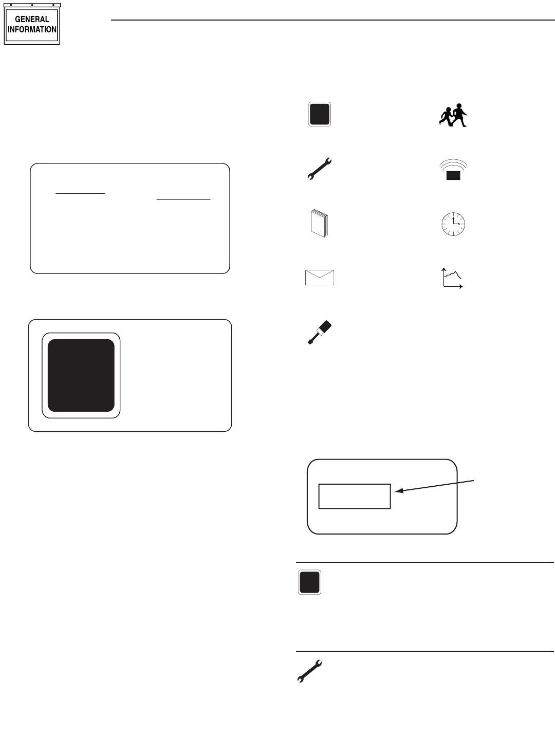
THE MENU SYSTEM
Pressing any key will switch the display into menu
mode (Figure 8). If no further keys are pressed for
one minute, the unit will revert back to the status
display. Menu Mode is indicated by a menu name on
the right side of the display, and an icon (picture) on
the left side. Use the up/down arrow keys to move to
the menu required, then press the enter key to see
the choices.
Figure 8 — Menu System
T
+
STATUS DISPLAY
TEST MENU
L
O
GHISTORY MENU
EMAILALARMS EMAIL MENU
SETTINGS MENU
EXERCISE MENU
RADIO MENU
Time
TIME &
DATE MENU
t
GRAPH MENU
Once a menu is selected, there will be a list of choic-
es. The current choice is shown by a rectangle drawn
around it (Figure 9). Use the arrow keys to navigate
the rectangle to the topic required, then press the
enter key.
Figure 9 — Menu Choices
Choice 1
Choice 3
Choice 2
Use Arrow
Keys to Move
the Selector
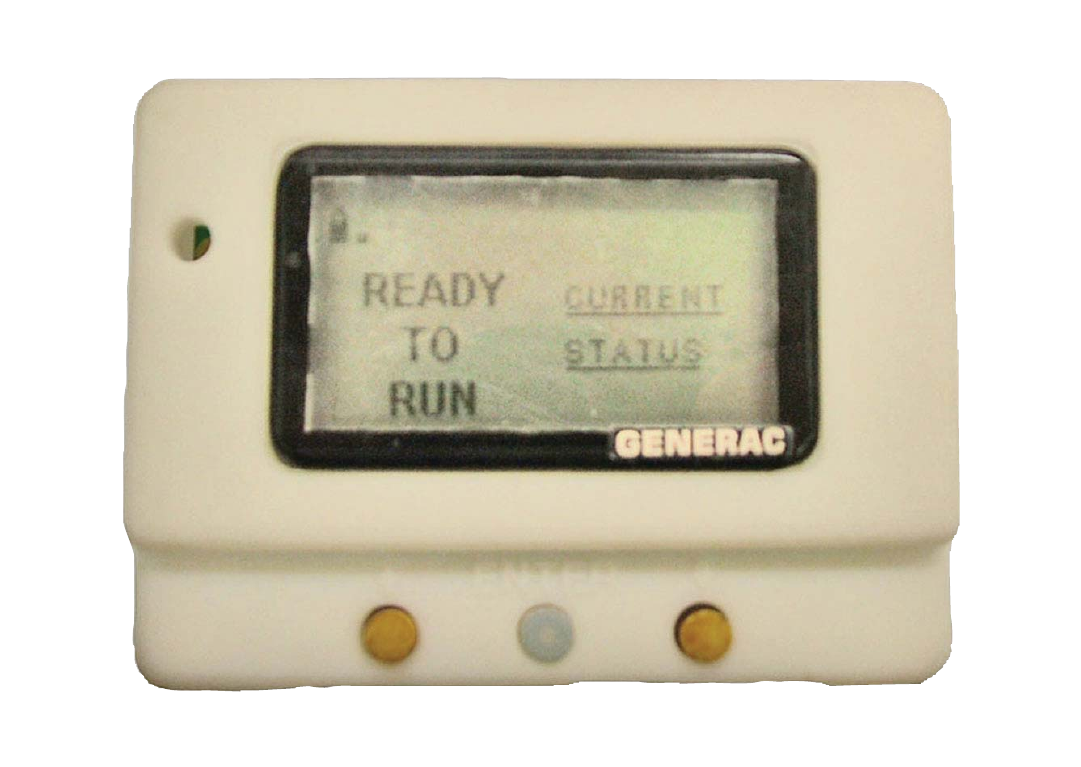
STATUS MENU
T
+
The status menu item simply provides a way to
show the current status message coming from
the generator. This is shown as a text message
on the LEFT hand side of the display. Normally this
will show the following message: “READY TO RUN”.
TEST MENU
The test menu permits starting and stopping
the generator. Use the arrow keys to navigate
to the appropriate option. If choosing to start
the generator, the two arrow keys will need to be
pressed together to confirm the command. To cancel
the command, press the enter key.
Wireless Display System
7
If the generator can run at a low speed (Quiet Test
QT), this option is available. If there is an automatic
transfer switch, there is the option to run the genera-
tor and transfer onto generator power. Once the gen-
erator is started or stopped, the state of the generator
will be shown by a “*” symbol next to the command
issued. For example:
Normal Start* You started the generator at
normal speed.
Start & transfer* You started the generator
& transferred to generator
power
Low speed start* You started the generator at
low speed (Quiet Test)
Stop generator* You stopped the generator
There is a one minute cooldown time after you stop
the generator, so it will continue to operate for one
minute after the stop command is issued. In the event
that the stop command fails (such as if you take the
display out of range, you can either retry the stop
command or manually stop the generator by switch-
ing it to the “off” position.
HISTORY MENU
L
O
G
The history log is a chronological list of
“events” that have occurred to the generator.
An event is any change in status such as an
alarm, a start or stop, the keyswitch being operated,
etc.. These events are permanently stored inside the
display module along with a time and date stamp
when they occurred. They will not be lost even if the
battery goes dead, but there is the option to erase the
log.
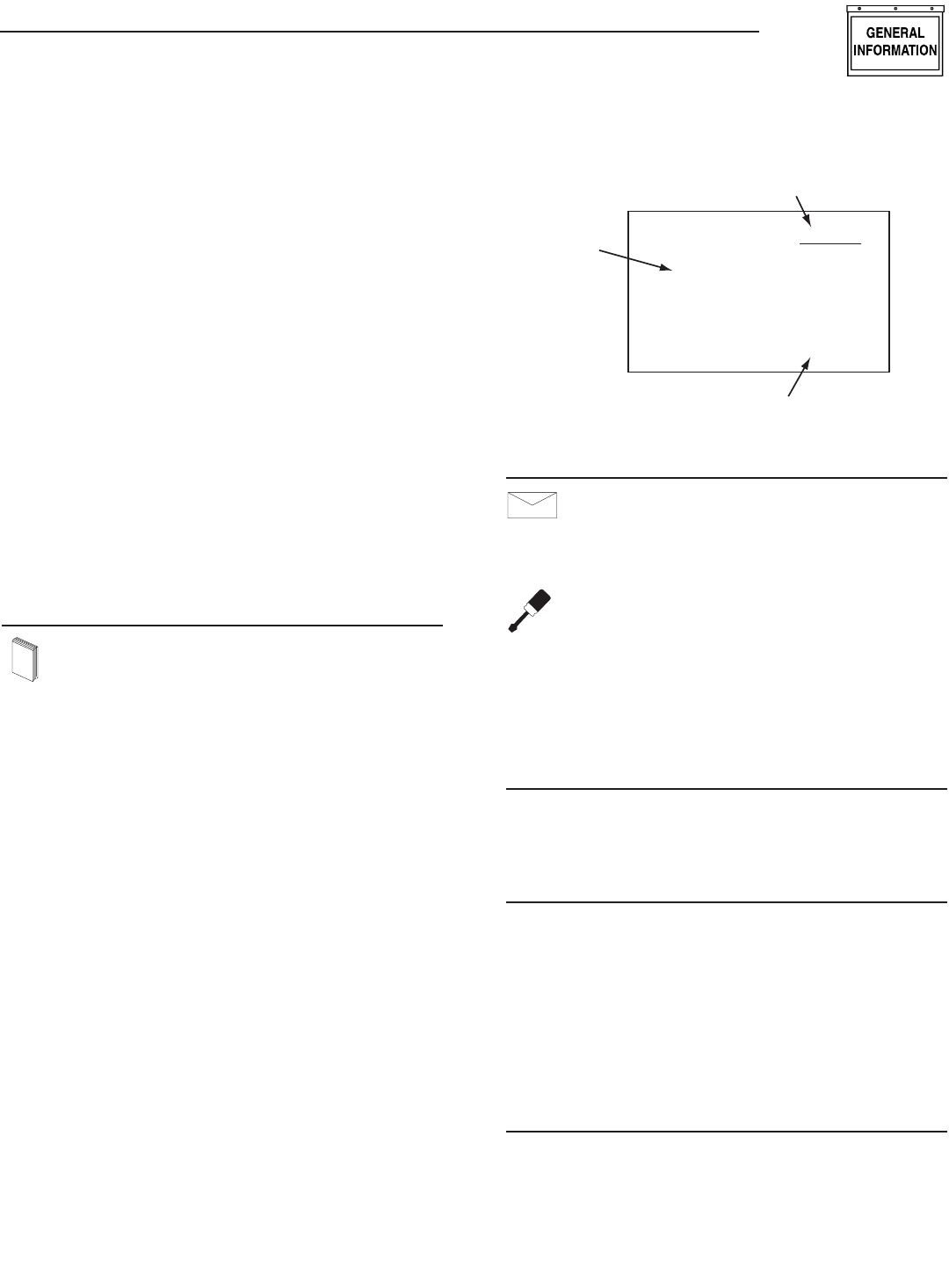
When entering the history menu, the most recently
logged event (Event 1) will be displayed. The actual
event will be shown as a message on the left hand
portion of the screen (Figure 10). The time and date
of the event will be shown on the right hand part of
the screen, and the event number displayed on the
underlined title bar. By using the arrow keys, navigate
through the events which are stored in chronological
order. Event 1 is the most recent and event 100 is the
oldest. The events are stored in a circular fashion so
it's possible to scroll from Event 1 back to event 100
by using the “UP” arrow key. The history log can be
cleared from the “SETTINGS” menu.
Figure 10 — History Menu
HIGH
COOLANT
TEMP.
EVENT 7
TIME
10:11:12
DATE
02/02/02
Event Number
Time & Date of the Event
Event
Type
EMAIL MENU
EMAILALARMS
Currently this menu has no function.
SETTINGS MENU
The following list of options will be presented:
Adjust Contrast
AC Threshold
Service Schedule
Clear History
Add me to network.
ADJUST CONTRAST
The display contrast can be adjusted using the
two arrow keys. Once the desired contrast level is
reached, press the enter key to store it.
VAC THRESHOLD
Adjust the AC voltage level used by the generator to
determine if the utility is bad. If the utility voltage
falls below this level, the generator will start. Note
that if the generator battery is ever disconnected or
goes dead, this setting will need to be re-entered.
The range of adjustment is limited by the generator
(for example – a maximum of 170 VAC on air-cooled
units) even though the display allows a larger range.
This is to accommodate different models.
SERVICE SCHEDULE
The display can be set to alarm on a specific date
for an alert that a service is required. The date is
set using the two arrow keys. Setting the month to
zero disables this whole function. When the alarm
occurs, it can be cancelled by re-setting the service
date only.
•
•
•
•
•
Wireless Display System

8
EXERCISE MENU
Normally the exercise time is set on the gen-
erator control board as it powers up. If an
exercise time has not been set on the control
board, all it’s LED’s will flash and an alarm will be set
on the wireless display – “EXERCISE TIME NOT
SET”.
The exercise page of the wireless display can be used
to overwrite any exercise time set in the generator.
Use the arrow keys and follow the on-screen instruc-
tions to set the time and day. The wireless display cal-
culates the difference in time from the exercise date
and time to the current date and time, and down-
loads this to the generator. This means you MUST set
the correct date and time on the display. The exercise
cycle is repeated at the same time weekly and does
not use the wireless system to do this, all the timing
is in the generator. If you ever remove power from the
generator, you will need to re-set the exercise time
when you re-set the radio (see the reset radio com-
mand in the radio menu section).
RADIO MENU
The following list of options will be presented:
Radio information
Change Channel
Reset Radio
Add New Display
Test Radio Link
RADIO INFORMATION
This selection shows statistics about the radio link.
There are displays of signal strength and signal qual-
ity as percentages, as well as an indication of the
current system channel. For ease of use, the display
will NOT revert to the status/alarm screen after one
minute if no keys are pressed.
If the signal strength is poor, re-locate the display to
somewhere with a higher signal strength. Unplug the
wall adapter and walk around while observing the
signal strength. Mount the unit at a point where the
signal strength is at a high level (not necessarily the
highest level). The transceiver at the generator end
can then be relocated. The best position for this is as
high up as possible away from any structures.
If the signal quality is low but the signal strength is
good, there may be some interference. See the section
on "Changing Channels".
•
•
•
•
•
CHANGING CHANNELS
Channel selection is normally automatic, manually
changing channels should only need to be done if
experiencing interference from other equipment. This
can be identified by looking at the signal strength and
the signal quality. If the signal strength is good but
the quality is not, there may be some interference.
Changing channels on the main display will auto-
matically change the channel on the generator end
provided a link has been established. If the “change
channel” message fails for any reason, the units will
revert to their old channel selection. A new channel
setting will be remembered for the next time the unit
is powered up. To change channels on an established
and working link, simply select “Change Channel”
from the Radio menu, then enter a new channel
number.
Changing the channel number on a link that is not
established is a little more complex, the only reason
this may need to be done is if a link cannot be estab-
lish because the default channel is noisy. To perform
this task, follow these instructions:
1. Remove power from the generator end of the link.
Power up the display.
2. Go to the radio menu and select “Reset radio”.
This will try and establish a link but it will fail,
the process will take about one minute.
3. Go to the “Change Channel” menu and select a
new channel.
4. Go back and select the “Reset Radio” command
and immediately turn on the generator end of the
link.
5. The radio link should establish itself on the chan-
nel selected. This will be remembered even when
the power is turned off to the display.
If the unit is a secondary display, no checking is done
to ensure the channel matches the current system
channel. Set the channel to the current system chan-
nel. Look on the main display and select the radio
menu, then select “Radio Information”. This will tell
you the current channel that is being used.
RESET RADIO
Normally the system will set itself up out of the box,
however if you have to replace either of the transceiv-
ers ( the display or the generator end), or if power is
ever lost to the generator end (such as a flat genera-
tor battery) you will need to re-train the system and
re-set the exercise time. You will NOT have to re-train
the system if the battery in the display goes flat, the
system will remember the radio settings.
If communications are totally lost for an unexplained
reason, you may want to perform a new radio setup.
1. Carry the display to a point near the generator
and turn it on. Go to the radio menu.
Wireless Display System
9
2. Disconnect the transceiver at the generator end,
then reconnect it. You now have one (1) minute to
complete the setup process.
3. On the display select “Reset Radio”. The display
will show it is searching for the generator, this
process will last one minute and a countdown
timer will be displayed.
4. Once the time is up a message will be displayed
showing that the generator has been found. The
radio settings will be remembered for the next
time.
5. Re-set the exercise time.
ADD NEW DISPLAY
A second (third or fourth) display can be added to
the network. Each display needs to be trained as to
what it’s network consists of. This is the function of
the “Add New Display” selection.
1. Locate the new display near the main display and
turn it on.
2. On the NEW display, go to the “Settings” menu
and select “Add me to Network”.
3. Choose a unique address for the additional dis-
play, for example one that does not conflict with
any other additional displays. If there are only
two displays, then any number (other than zero),
will do. Zero is used to cancel the command.
4. On the MAIN display go to the radio menu and
select “Add New Display”. Press enter on both
displays. A countdown timer will be displayed as
the two units re-train.
5. At the end of the period, the new display will
show that the training was successful.
TEST RADIO LINK
This feature allows the “basic” data integrity of the
link to be tested, it may not be necessary to use this
feature. For ease of use, the display will NOT revert
to the status/alarm screen after one minute if no keys
are pressed.
Test data is sent over the link to the generator end,
and then sent back from the generator end to the
display. The data received is displayed on the bottom
line of the display. Good data is shown as a series of
forward slashes (//////). Timeouts on the link are dis-
played as the “#” character and corrupted data reply
messages are shown as the “@” character. The mes-
sages are termed “basic” because they are not error
checked or corrected.
Radio information such as signal strength, channel
number and quality is also shown alongside the test
data.
TIME & DATE MENU
Time
There is a display of the current time, day, and
date shown on the menu icon page. Only the
time display will update, the date display is
just a snapshot of the current date (Figure 11).
Figure 11 — Time & Date Menu
MENU
TIME
AND
DATE
04/17/07
Monday
15:25:03
Time
Selecting this menu permits setting the clock to the
correct time, day and date. This will only need to be
done the first time they system is powered up, or
to correct any small errors in the time. Use the two
arrow keys to set the correct time, day and date.
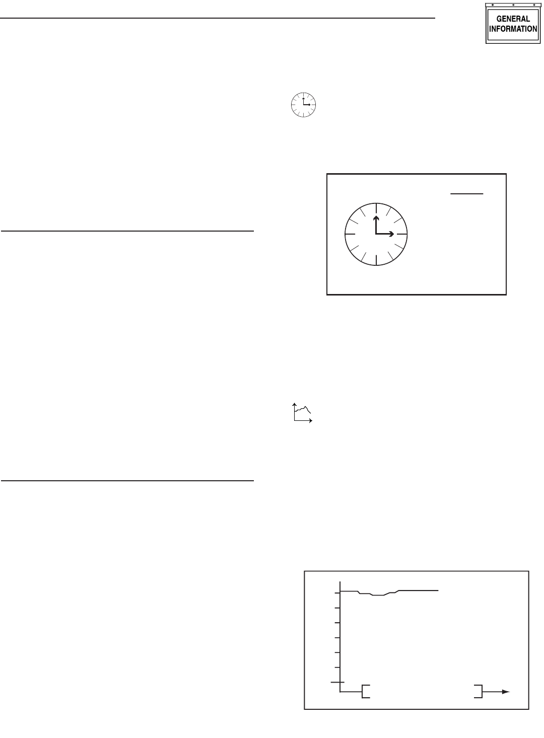
GRAPH MENU
t
The Graph menu permits graphing data in real
time on a rolling screen (Figure 12). Choose
what to graph from the following list:
Utility Voltage
Generator Battery Volts
Generator RPM (in units of RPM x 100)
Current up to 170A (20kW) - certain models only
The display is updated with a new point every 200ms
so it takes about 25 seconds to scroll the whole
screen. However new data is only read from the gen-
erator every two (2) seconds.
Figure 12 — Sample Graph of Engine RPM
36
30
24
18
Engine RPM t
•
•
•
•
Wireless Display System
Part No. 0G5812 Revision A (07/20/07) Printed in U.S.A.
P.O. BOX 8 • WAUKESHA, WI 53187
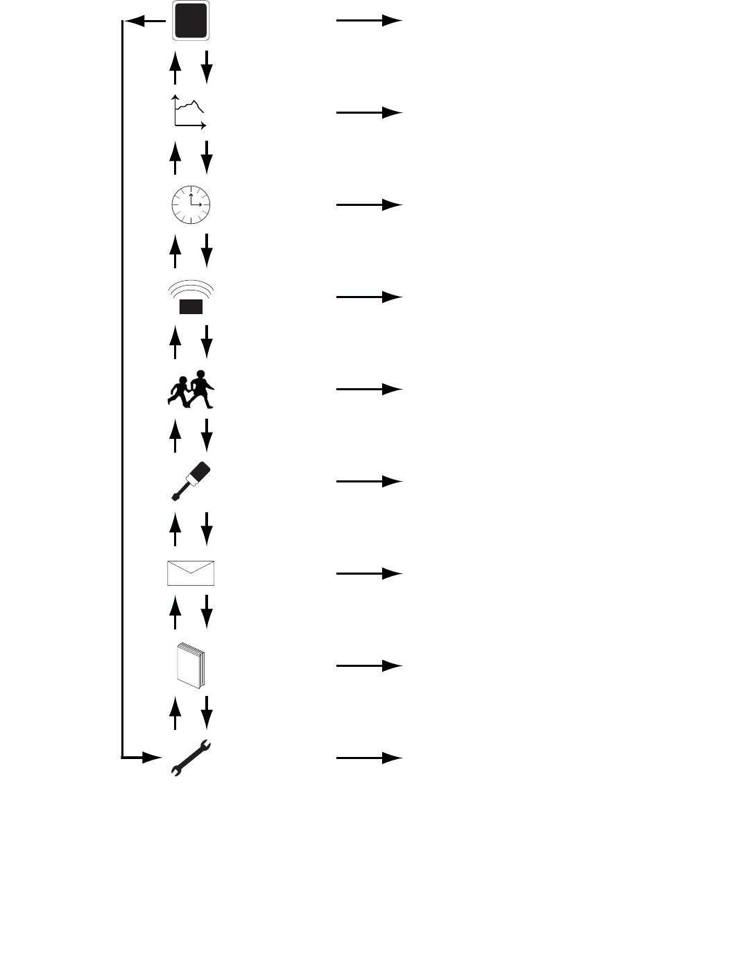
MENU MAP
T
+
STATUS Display Status Information
TEST
1. Normal Start
2. Start & Transfer
3. Low Speed Start
4. Stop Generator
L
O
GHISTORY Display the History Log
EMAILALARMS EMAIL Reserved for Future Use
SETTINGS
1. Adjust Contrast
2. Change VAC Threshold
3. Set Up a Service Schedule
4. Clear History Log
5. Add Me to Network
EXERCISE Set an Exercise Time and Day
Select Low or High Speed Exercise
RADIO
1. Show Radio Information
2. Change Channels
3. Reset Radio
4. Add New Display
5. Test Radio Link
Time
TIME &
DATE Set the Clock and Calendar
t
GRAPH
Graph - Generator Battery Voltage
- Generator RPM
- Current
- Utility Voltage
Up Down