Generac Power Systems 0G6020A Wireless Display User Manual 0G8898revE indd
Generac Power Systems Wireless Display 0G8898revE indd
Manual
Wireless Display
System
Instruction Manual
Proof #1
01/15/09
TABLE OF CONTENTS
SAFETY ........................................................... Inside Front Cover
Read This Manual Thoroughly ........................................... 1
Safety Rules ..................................................................... 1
Operation and Maintenance ............................................... 3
How to Obtain Service ...................................................... 3
INTRODUCTION ........................................................................ 3
BATTERY OPERATION ............................................................... 3
INSTALLATION .......................................................................... 4
Generator Side Transceiver Installation Instructions ........... 4
Display Installation ............................................................ 5
THE COMMUNICATIONS LED .................................................... 6
GENERATOR COMMUNICATIONS .............................................. 6
THE DISPLAY ............................................................................ 6
Contrast Adjustment ......................................................... 6
Backlight .......................................................................... 6
Buttons ............................................................................. 7
Battery and Signal Strength Indicators ............................... 7
ALARM AND STATUS DISPLAY .................................................7
THE MENU SYSTEM ................................................................. 7
Status Menu ..................................................................... 8
Test Menu ......................................................................... 8
History Menu .................................................................... 8
SETTINGS MENU ...................................................................... 9
Adjust Contrast ................................................................. 9
EXERCISE MENU ...................................................................... 9
RADIO MENU ............................................................................ 9
Radio Information ............................................................. 9
Changing Channels ........................................................... 9
Reset Radio ...................................................................... 9
Add New Display ............................................................ 10
Test Radio Link ............................................................... 10
TIME & DATE MENU ............................................................... 10
GRAPH MENU ......................................................................... 10
MENU MAP ............................................................................. 11
FADD ASSEMBLY .................................................................... 12
NOTES .................................................................................... 13
WARRANTY ...............................................................Back Cover
SAFETY
Compliance Statement (Part 15.19)
This device complies with Part 15 of the FCC Rules.
Operation is subject to the following two conditions:
1. This device may not cause harmful interference, and
2. This device must accept any interference received, including
interference that may cause undesired operation.
Warning (Part 15.21)
Changes or modifications not expressly approved by the party
responsible for compliance could void the user's authority to
operate the equipment.
FCC Interference Statement (Part 15.105 (b))
This equipment has been tested and found to comply with the
limits for a Class B digital device, pursuant to Part 15 of the
FCC Rules. These limits are designed to provide reasonable
protection against harmful interference in a residential instal-
lation. This equipment generates uses and can radiate radio
frequency energy and, if not installed and used in accordance
with the instructions, may cause harmful interference to radio
communications. However, there is no guarantee that interfer-
ence will not occur in a particular installation. If this equipment
does cause harmful interference to radio or television reception,
which can be determined by turning the equipment off and on,
the user in encouraged to try to correct the interference by one
of the following measures:
Reorient or relocate the receiving antenna.•
Increase the separation between the equipment and receiver.•
Connect the equipment into an outlet on a circuit different from •
that to which the receiver is connected.
Consult the dealer or an experienced radio/TV technician for •
help.
To comply with FCC/IC RF exposure limits for general population
/ uncontrolled exposure, the antenna(s) used for this transmitter
must be installed to provide a separation distance of at least 20
cm from all persons and must not be co-located or operating in
conjunction with any other antenna or transmitter.
RF Exposure (OET Bulletin 65)
To comply with FCC/IC RF exposure requirements for mobile
transmitting devices, this transmitter should only be used or
installed at locations where there is at least 20 cm separation
distance between the antenna and all persons.
Section 7.1.5 of RSS-GEN
Operation is subject to the following two conditions:
1. This device may not cause interference, and
2. This device must accept any interference, including interfer-
ence that may cause undesired operation of the device.
Table of Contents
1
Important Safety Instructions
READ THIS MANUAL THOROUGHLY
If any portion of this manual is not understood, contact the near-
est Authorized Service Dealer for starting, operating and servicing
procedures.
Throughout this publication, and on tags and decals affixed to the
generator, DANGER, WARNING, CAUTION and NOTE blocks are
used to alert personnel to special instructions about a particular
service or operation that may be hazardous if performed incor-
rectly or carelessly. Observe them carefully. Their definitions are
as follows:
DANGER
After this heading, read instructions that, if not
strictly complied with, will result in personal injury
or property damage.
After this heading, read instructions that, if not
strictly complied with, may result in personal inju-
ry or property damage.
After this heading, read instructions that, if not
strictly complied with, could result in damage to
equipment and/or property.
NOTE:
After this heading, read explanatory statements that require
special emphasis.
These safety warnings cannot eliminate the hazards that they
indicate. Common sense and strict compliance with the special
instructions while performing the service are essential to prevent-
ing accidents.
Four commonly used safety symbols accompany the DANGER,
WARNING and CAUTION blocks. The type of information each
indicates is as follows:
This symbol points out important safety information
that, if not followed, could endanger personal safety
and/or property of others.
This symbol points out potential explosion hazard.
This symbol points out potential fire hazard.
This symbol points out potential electrical shock
hazard.
Study these SAFETY RULES carefully before installing, operating
or servicing this equipment. Become familiar with this Owner’s
Manual and with the unit. The generator can operate safely, effi-
ciently and reliably only if it is properly installed, operated and
maintained. Many accidents are caused by failing to follow simple
and fundamental rules or precautions.
The manufacturer cannot anticipate every possible circumstance
that might involve a hazard. The warnings in this manual, and on
tags and decals affixed to the unit are, therefore, not all inclusive.
If using a procedure, work method or operating technique that
the manufacturer does not specifically recommend, ensure that
it is safe for all personnel. Also make sure the procedure, work
method or operating technique utilized does not render the genera-
tor unsafe.
DANGER
Despite the safe design of this generator,
operating this equipment imprudently, neglect-
ing its maintenance or being careless can cause
possible injury or death. Permit only responsible
and capable persons to install, operate or main-
tain this equipment.
Potentially lethal voltages are generated by
these machines. Ensure all steps are taken to
render the machine safe before attempting to
work on the generator.
Parts of the generator are rotating and/or hot
during operation. Exercise care near running
generators.
The engine exhaust from this product
contains chemicals known to the state
of California to cause cancer, birth
defects or other reproductive harm.
WARNING:
This product contains or emits chemicals
known to the state of California to cause
cancer, birth defects or other reproductive harm.
WARNING:
SAVE THESE INSTRUCTIONS – The manufacturer suggests that these rules for safe operation be copied and posted in
potential hazard areas. Safety should be stressed to all operators, potential operators, and service and repair technicians
for this equipment.
SAVE THESE INSTRUCTIONS – This manual contains important instructions that should be followed during installation and
maintenance of the generator and batteries.

2
Important Safety Instructions
GENERAL HAZARDS
For safety reasons, the manufacturer recommends that this •
equipment be installed, serviced and repaired by an Authorized
Service Dealer or other competent, qualified electrician or
installation technician who is familiar with applicable codes,
standards and regulations. The operator also must comply with
all such codes, standards and regulations.
Installation, operation, servicing and repair of this (and related) •
equipment must always comply with applicable codes, stan-
dards, laws and regulations. Adhere strictly to local, state and
national electrical and building codes. Comply with regulations
the Occupational Safety and Health Administration (OSHA) has
established. Also, ensure that the generator is installed, operat-
ed and serviced in accordance with the manufacturer’s instruc-
tions and recommendations. Following installation, do nothing
that might render the unit unsafe or in noncompliance with the
aforementioned codes, standards, laws and regulations.
The engine exhaust fumes contain carbon monoxide gas, •
which can be DEADLY. This dangerous gas, if breathed in suf-
ficient concentrations, can cause unconsciousness or even
death. For that reason, adequate ventilation must be provided.
Exhaust gases must be piped safely away from any building or
enclosure that houses the generator to an area where people,
animals, etc., will not be harmed. This exhaust system must be
installed properly, in strict compliance with applicable codes
and standards.
Keep hands, feet, clothing, etc., away from drive belts, fans, •
and other moving or hot parts. Never remove any drive belt or
fan guard while the unit is operating.
Adequate, unobstructed flow of cooling and ventilating air is •
critical in any room or building housing the generator to prevent
buildup of explosive gases and to ensure correct generator
operation. Do not alter the installation or permit even partial
blockage of ventilation provisions, as this can seriously affect
safe operation of the generator.
Keep the area around the generator clean and uncluttered. •
Remove any materials that could become hazardous.
When working on this equipment, remain alert at all times. •
Never work on the equipment when physically or mentally
fatigued.
Inspect the generator regularly, and promptly repair or replace •
all worn, damaged or defective parts using only factory-
approved parts.
Before performing any maintenance on the generator, discon-•
nect its battery cables to prevent accidental start-up. Disconnect
the cable from the battery post indicated by a NEGATIVE, NEG
or (–) first. Reconnect that cable last.
Never use the generator or any of its parts as a step. Stepping •
on the unit can stress and break parts, and may result in dan-
gerous operating conditions from leaking exhaust gases, fuel
leakage, oil leakage, etc.
ELECTRICAL HAZARDS
All generators covered by this manual produce dangerous elec-•
trical voltages and can cause fatal electrical shock. Utility power
delivers extremely high and dangerous voltages to the transfer
switch, as does the standby generator. Avoid contact with bare
wires, terminals, connections, etc., on the generator as well as
the transfer switch, if applicable. Ensure all appropriate covers,
guards and barriers are in place before operating the generator.
If work must be done around an operating unit, stand on an
insulated, dry surface to reduce shock hazard.
Do not handle any kind of electrical device while stand-•
ing in water, while barefoot, or while hands or feet are wet.
DANGEROUS ELECTRICAL SHOCK MAY RESULT.
If people must stand on metal or concrete while installing, •
operating, servicing, adjusting or repairing this equipment,
place insulative mats over a dry wooden platform. Work on the
equipment only while standing on such insulative mats.
The National Electrical Code (NEC), Article 250 requires the •
frame and external electrically conductive parts of the generator
to be connected to an approved earth ground and/or ground-
ing rods. This grounding will help prevent dangerous electrical
shock that might be caused by a ground fault condition in
the generator set or by static electricity. Never disconnect the
ground wire.
Wire gauge sizes of electrical wiring, cables and cord sets must •
be adequate to handle the maximum electrical current (ampac-
ity) to which they will be subjected.
Before installing or servicing this (and related) equipment, make •
sure that all power voltage supplies are positively turned off at
their source. Failure to do so will result in hazardous and pos-
sibly fatal electrical shock.
Connecting this unit to an electrical system normally supplied •
by an electric utility shall be by means of a transfer switch so as
to isolate the generator electric system from the electric utility
distribution system when the generator is operating. Failure to
isolate the two electric system power sources from each other
by such means, will result in damage to the generator and may
also result in injury or death to utility power workers due to
backfeed of electrical energy.
Generators installed with an automatic transfer switch will crank •
and start automatically when normal (utility) source voltage is
removed or is below an acceptable preset level. To prevent such
automatic start-up and possible injury to personnel, disable the
generator’s automatic start circuit (battery cables, etc.) before
working on or around the unit. Then, place a “Do Not Operate”
tag on the generator control panel and on the transfer switch.
In case of accident caused by electric shock, immediately •
shut down the source of electrical power. If this is not pos-
sible, attempt to free the victim from the live conductor. AVOID
DIRECT CONTACT WITH THE VICTIM. Use a nonconducting
implement, such as a dry rope or board, to free the victim from
the live conductor. If the victim is unconscious, apply first aid
and get immediate medical help.
Never wear jewelry when working on this equipment. Jewelry •
can conduct electricity resulting in electric shock, or may get
caught in moving components causing injury.

3
FIRE HAZARDS
Keep a fire extinguisher near the generator at all times. Do NOT •
use any carbon tetra-chloride type extinguisher. Its fumes are
toxic, and the liquid can deteriorate wiring insulation. Keep the
extinguisher properly charged and be familiar with its use. If
there are any questions pertaining to fire extinguishers, consult
the local fire department.
EXPLOSION HAZARDS
Properly ventilate any room or building housing • the generator to
prevent build-up of explosive gas.
Do not smoke around the generator. Wipe up any fuel or oil •
spills immediately. Ensure that no combustible materials are left
in the generator compartment, or on or near the generator, as
FIRE or EXPLOSION may result. Keep the area surrounding the
generator clean and free from debris.
These generator sets may operate using one of several types •
of fuels. All fuel types are potentially FLAMMABLE and/or
EXPLOSIVE and should be handled with care. Comply with all
laws regulating the storage and handling of fuels. Inspect the
unit’s fuel system frequently and correct any leaks immediately.
Fuel supply lines must be properly installed, purged and leak
tested according to applicable fuel-gas codes before placing
this equipment into service.
Diesel fuels are highly FLAMMABLE. Gaseous fluids such •
as natural gas and liquid propane (LP) gas are extremely
EXPLOSIVE. Natural gas is lighter than air, and LP gas is heavier
than air; install leak detectors accordingly.
OPERATION AND MAINTENANCE
The operator is responsible for proper and safe use of the equip-
ment. The manufacturer strongly recommends that the operator
read this Owner's Manual and thoroughly understand all instruc-
tions before using this equipment. The manufacturer also strongly
recommends instructing other users to properly start and operate
the unit. This prepares them if they need to operate the equipment
in an emergency.
It is the operator's responsibility to perform all safety checks, to
make sure that all maintenance for safe operation is performed
promptly, and to have the equipment checked periodically by
an Authorized Service Dealer. Normal maintenance service and
replacement of parts are the responsibility of the owner/operator
and, as such, are not considered defects in materials or workman-
ship within the terms of the warranty. Individual operating habits
and usage contribute to the need for maintenance service.
Proper maintenance and care of the generator ensures a minimum
number of problems and keeps operating expenses at a minimum.
See an Authorized Service Dealer for service aids and acces-
sories.
Operating instructions presented in this manual assume that
the standby electric system has been installed by an Authorized
Service Dealer or other competent, qualified contractor. Installation
of this equipment is not a “do-it-yourself” project.
HOW TO OBTAIN SERVICE
When the generator requires servicing or repairs, contact an
Authorized Service Dealer for assistance. Service technicians
are factory-trained and are capable of handling all service needs
(1-800-333-1322).
When contacting an Authorized Service Dealer about parts and
service, always supply the complete model number of the unit
as given on the front cover of this manual or on the DATA LABEL
affixed to the unit.
INTRODUCTION
The wireless display system consists of two identical radio trans-
ceivers, one mounted near the generator and the other (the one
with the display), should be in a convenient viewing location. The
system has a “line of sight” range of about 500 feet but this will
be reduced if the signal has to go through walls, etc.. The display
is intended to show the status of the generator and warn you if the
system is in an alarm state. It also provides the following additional
functions:
An independent (of the generator Alarm log) time/date stamped •
history of generator events such as starting and stopping
Allows remote starting and stopping of the generator•
Facility to set an exercise time and day from the display•
A separate battery backed clock (with date facility) which is •
synchronized to the generator clock. If power is removed from
the generator, time and date can be automatically restored from
this clock.
Ability to add extra displays•
Graphing capability•
The unit can be either battery powered or fed from the AC adapter
supplied (Part No. 0G4904). This adapter is rated for 100/240
VAC, 50/60 Hz operation. The History is kept in permanent mem-
ory that is not lost even when all power is lost. The clock function
is kept alive by a separate, 10 year life battery.
BATTERY OPERATION
The wireless display can be operated either from a plug in wall
transformer or from three AAA alkaline batteries. The unit is NOT
designed to run continuously on battery power. The batteries can
be rechargeable but are NOT recharged from the wall transformer
and should be separately charged. In the case of battery opera-
tion, the unit will go to sleep for 60 seconds then exchange data
for up to two (2) seconds to conserve battery life. The display
screen will turn off in the sleep mode unless there is an alarm to
be displayed. It can be awoken by pressing the ENTER key after
which it will remain awake for one (1) minute if no further keys
are pressed. The batteries are NOT used to retain data such as the
history log or the radio settings, they will not be lost in the event
of a dead battery.
NOTE 1:
In battery sleep mode it will take up to two (2) minutes to detect
if the radio link is lost. This long delay is to allow for the unit’s
sleep time.
Wireless Display System
4
NOTE 2:
In battery sleep mode, if the wall transformer is plugged into the
unit, it will take up to one minute to recognize this fact.
INSTALLATION
GENERATOR SIDE TRANSCEIVER INSTALLATION
INSTRUCTIONS
The following steps will illustrate how to mount the generator side
transceiver to the generator.
Disconnect all power sources prior to opening
the control panel.
1. Set the Auto/Off/Manual switch to the Off position.
2. Remove the 15Amp control panel fuse.
3. Disconnect the Positive battery cable.
4. Turn off the 240Vac Utility source voltage to the control
panel.
5. Remove the control panel cover.
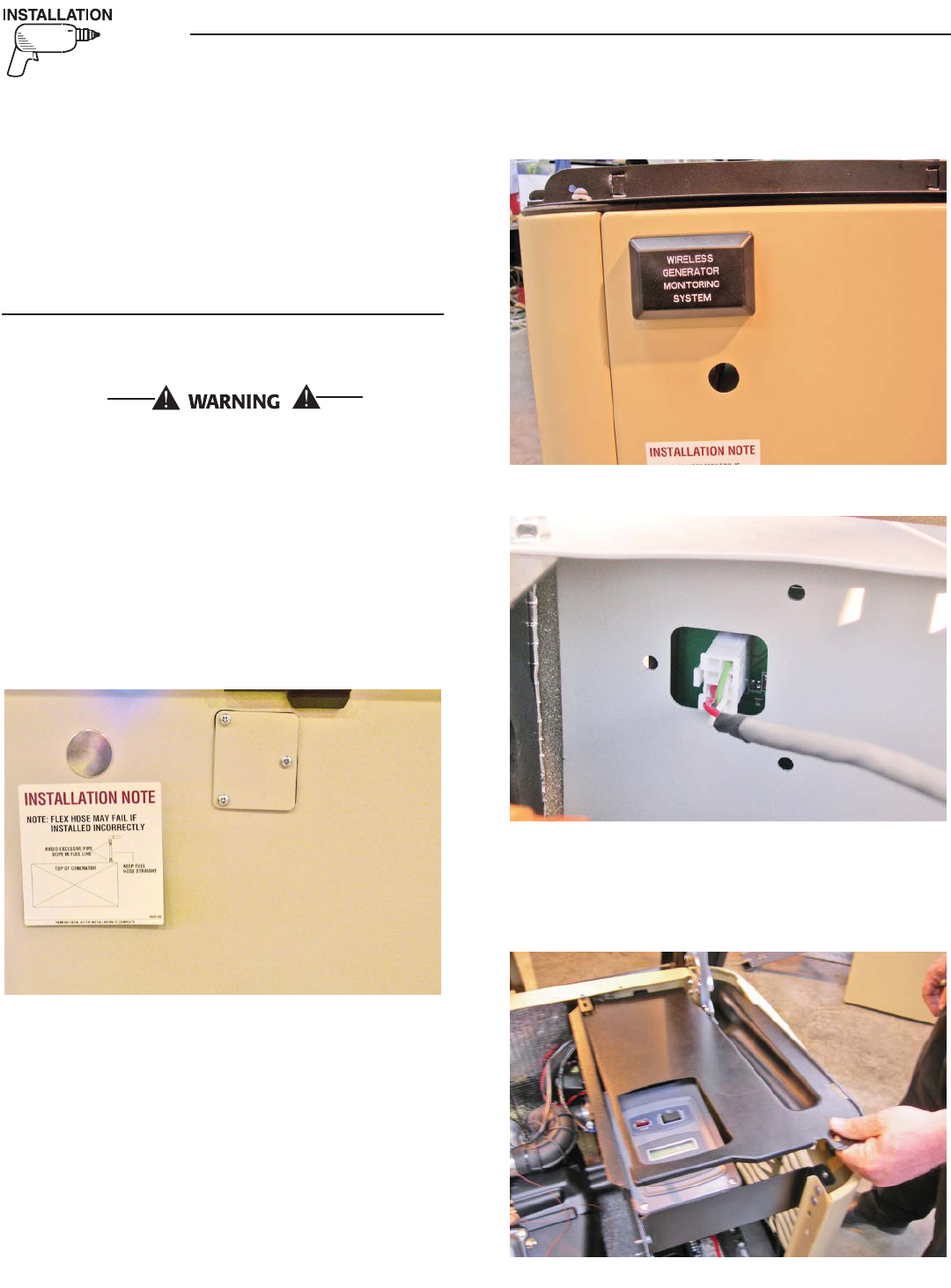
6. Remove the metal plate and rubber gasket from the back side
of the generator. (Figure 1.)
Figure 1 — Remove Metal Plate & Rubber Gasket
7. Remove the generator transceiver from the anti static bag and
verify the gasket is properly fitted in the groove.
8. Mount the generator transceiver to the generator using the two
(2) screws and flat washers provided (Figure 2).
9. Plug the wire harness into the transceiver module aligning the
plug latch with the header latch (Figure 3).
NOTE:
The plug will only plug into the header one way – DO NOT force
the plug into the header; gently insert the plug until it locks into
place.
Figure 2 — Mount Transceiver
Figure 3 — Plug in Wire Harness
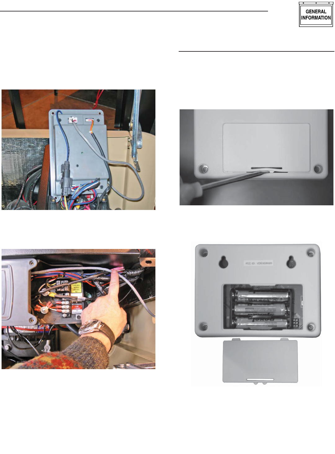
10. Undo the four (4) screws holding the control panel and raise
up the front end of the control panel so it's standing up (Figure
4).
Figure 4 — Stand Up Control Panel Front
Wireless Display System
5
Wireless Display System
11. Plug the other end of the wire harness into the 8-way connec-
tor at the top of the control panel. The plug will only plug in
one way (Figure 5). DO NOT force the plug into the header.
Gently insert the plug until it locks into place.
Figure 5 — Plug Wire Harness into Header J5
12. Route the wire in the channel along the left hand wall along
with the other wires (Figure 6).
Figure 6 — Route Wire
13. Replace the control panel front.
14. Replace the control panel cover.
15. Turn on the 240Vac Utility source voltage.
16. Reconnect the positive battery cable.
17. Replace the 15Amp control panel fuse.
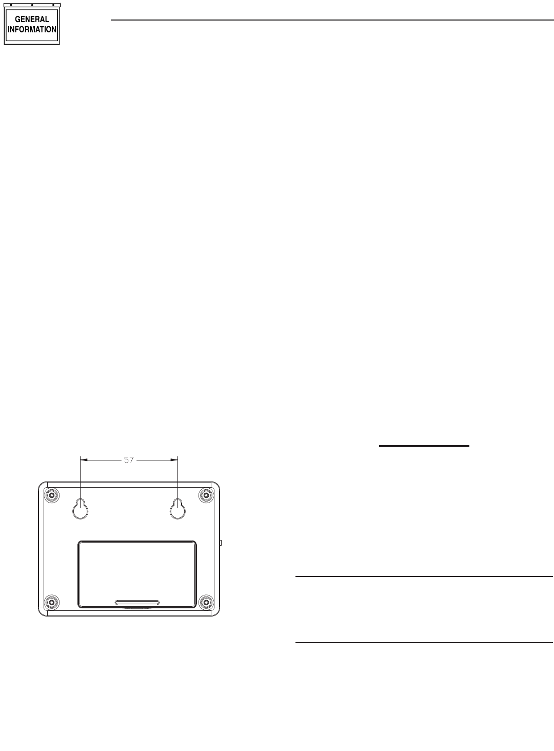
DISPLAY INSTALLATION
For easier installation, the batteries should first be fitted into the
display unit (Figure 7). This will allow you to walk around and
find the best location for the unit while still receiving good signal
strength. Attach the other transceiver to the generator as described
in the previous section.
Figure 7 — Open Display Unit
1. Insert the batteries (Figure 8).
Figure 8 — Insert Batteries
2. Reset the generator control panel by removing the fuse
on the front cover and then replace it. PERFORM STEP 3
IMMEDIATELY AFTER.
3. IMMEDIATELY turn on the generator display, up to one minute
will pass while the generator tries to find it’s display.
6
4. The display will show that it is searching for the generator and
the yellow LED may flash occasionally as it receives data from
the generator transceiver. This is due to the unit searching for
the correct channel.
5. Once the generator is found, the radio link is now established
and the settings will be remembered next time the display unit
is turned on. If the generator is not found, an error message
will briefly be shown, and the yellow LED will flash at one (1)
second intervals to indicate the display unit was unable to find
the generator. Repeat steps 2 and 3 with the Display closer to
the generator.
6. If the generator is not talking to it’s transceiver, but the radios
are talking to each other, this will be indicated by an appropri-
ate alarm which will be displayed after a 30 second period.
Check the wiring and connection to the generator.
7. Place the display at the preferred location. Do not permanently
mount it yet.
8. Plug the wall transformer into the display so as not to use
up the batteries. Familiarize personnel with the radio menu
(by reading the manual in conjunction with operating the
display).
9. Monitor the signal strength by looking at the display of signal
strength bars on the display (Figure 11). Note that it takes
a few seconds for the display to update the signal strength
display. Relocate the display if the signal strength is poor or
non-existent.
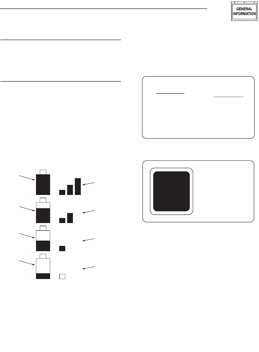
10. Mount the display using the holes on the back to hang onto
two suitably sized fixing screws in the drywall 2¼ inches
apart. It should be vertically mounted on a wall BETWEEN
studs for maximum signal strength (Figure 9).
Figure 9 — Mounting Holes
11. Once a link is established, the display will "remember" it's
own generator and will not need to search for it again after it
is turned off and back on. If the battery is ever disconnected
at the generator end, the generator will search for the display
when the battery is reconnected. It is important that the dis-
play is powered from the wall transformer at this time and
not it's internal battery. This is because the display would
normally be in sleep mode when powered from it's battery
and the generator would be unable to find it.
12. Set the time and date into the clock, use the instructions
given in the "Time and Date Menu" section. The time and date
will be remembered even if the battery goes dead. There is a
separate, replaceable 10 year battery for this function.
13. The communications LED will light solid to show data is being
received. A flashing LED indicates the unit was unable to find
the generator.
14. Set an exercise day and time now (see "Exercise Menu" sec-
tion).
THE COMMUNICATIONS LED
The communications LED will light solid to show data is being
received. If the LED flashes at regular one (1) second intervals, it
indicates the unit was unable to find the generator. Irregular flash-
ing is an indication of poorer reception.
GENERATOR COMMUNICATIONS
The transceiver requests data from the generator every two (2)
seconds and this is stored inside the transceiver locally. The data
is relayed to the base station over the radio link every time it is
requested by the display about every two (2) seconds. When on
battery power, the data is only requested every minute to con-
serve batteries. If the generator is not talking to it’s transceiver,
but the radios are talking to each other, this will be indicated by
an appropriate alarm which will be displayed after a seven (7)
second period (Figure 10). Check the wiring and connection to
the generator.
Figure 10 — Sample Alarm
WARNING
RADIO OK
BUT GEN
IS NOT
TALKING
THE DISPLAY
CONTRAST ADJUSTMENT
The display contrast can be adjusted from the “Settings” menu.
Any changes to the contrast setting will be remembered even if
power is removed from the display.
BACKLIGHT
The backlight is lit whenever a key is pressed. It will remain lit for
20 seconds if there are no further key presses. If an alarm occurs,
the backlight will flash at a one (1) second rate (not if battery
powered).
Wireless Display System
7
BUTTONS
Operation of the display is controlled by three (3) buttons labeled
+, —, and Enter. These buttons are used to navigate the display
to the required page, or to enter data. The +/— buttons are also
referred to as the arrow keys. Holding down a button for more than
half a second will cause it to auto repeat until it is released.
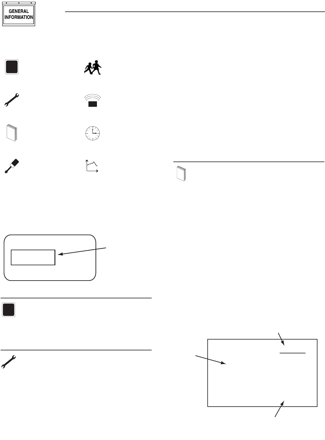
BATTERY AND SIGNAL STRENGTH INDICATORS
In the top left corner of the display, there are two icons (or
pictures) that give a quick indication of the state of the internal
battery and the radio signal strength (Figure 11). The battery is
represented by the left hand, single tall rectangle which is drawn as
being somewhere between full and empty. Full represents greater
than 75% capacity, mostly full represents 50-75% capacity, half
full represent 25-50% and mostly empty represents 0-25% capac-
ity. The signal strength icon is shown to the right of the battery
icon as three vertical bars representing greater than 25%, greater
than 50%, and greater than 75%. Three bars indicate excellent
signal strength, two bars represent good signal strength, one bar
represents weak signal strength. Two or three bars is the normal
indication.
Figure 11 — Battery & Signal Strength
Signal
Strength
Is Excellent
Battery
has more
than 75%
Capacity
Battery
has 50-75%
Capacity
Battery
has 25-50%
Capacity
Battery
has less
than 25%
Capacity
Signal
Strength
Is Good
Signal
Strength
Is Weak
No
Signal
ALARM AND STATUS DISPLAY
The display will normally show the operating status of the genera-
tor or an alarm message if one is present. See Figures 12 and
13.
Figure 12 — Sample Alarm Screen
WARNING
LOW
BATTERY
ALARM
Figure 13 — Sample Status Screen
T
+
RUNNING
AND
COOLING
DOWN
When a key is pressed, the display switches into menu mode
which will allow access to the special functions of the unit. If no
keys are pressed for 30 seconds, the unit will revert back to the
status or alarm display.
When an alarm occurs, the display will show a flashing alarm
icon and the alarm message. The backlight will also flash if not
in battery mode. If the alarm goes away, the display will revert to
the status display. If two or more alarms exist, the most recent
one to occur will be displayed. If a key is pressed to go into menu
mode, when returning to the alarm display, the latest alarm will be
displayed.
THE MENU SYSTEM
Pressing any key will switch the display into menu mode (Figure
14). If no further keys are pressed for one minute, the unit will
revert back to the status display. Menu Mode is indicated by a
menu name on the right side of the display, and an icon (picture)
on the left side. Use the up/down arrow keys to move to the menu
required, then press the enter key to see the choices.
Wireless Display System
8
Figure 14 — Menu System
T
+
STATUS DISPLAY
TEST MENU
L
O
GHISTORY MENU
SETTINGS MENU
EXERCISE MENU
RADIO MENU
Time
TIME &
DATE MENU
t
GRAPH MENU
Once a menu is selected, there will be a list of choices. The current
choice is shown by a rectangle drawn around it (Figure 15). Use
the arrow keys to navigate the rectangle to the topic required, then
press the enter key.
Figure 15 — Menu Choices
Choice 1
Choice 3
Choice 2
Use Arrow
Keys to Move
the Selector
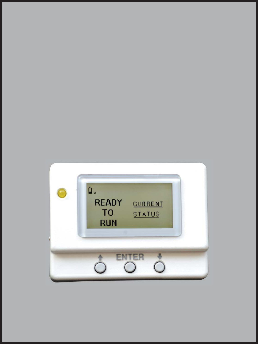
STATUS MENU
T
+
The status menu item simply provides a way to show the
current status message coming from the generator. This is
shown as a text message on the LEFT hand side of the
display. Normally this will show the following message: “READY
TO RUN”.
TEST MENU
The test menu permits starting and stopping the generator.
Use the arrow keys to navigate to the appropriate option.
If choosing to start the generator, the two arrow keys will
need to be pressed together to confirm the command. To cancel
the command, press the enter key.
If the generator can run at a low speed (Quiet Test QT), this option
is available. If there is an automatic transfer switch, there is the
option to run the generator and transfer onto generator power.
Once the generator is started or stopped, the state of the generator
will be shown by a “*” symbol next to the command issued.
For example:
Normal Start* You started the generator at nor-
mal speed.
Start & transfer* You started the generator & trans-
ferred to generator power
Low speed start* You started the generator at low
speed (Quiet Test)
Stop generator* You stopped the generator
There is a one minute cool down time after you stop the generator,
so it will continue to operate for one minute after the stop com-
mand is issued. In the event that the stop command fails (such as
if you take the display out of range, you can either retry the stop
command or manually stop the generator by switching it to the
“off” position.
HISTORY MENU
L
O
G
The history log is a chronological list of “events” that have
occurred to the generator. An event is any change in status
such as an alarm, a start or stop, the key switch being
operated, etc.. These events are permanently stored inside the
display module along with a time and date stamp when they
occurred. They will not be lost even if the battery goes dead, but
there is the option to erase the log. This log is independent of the
log displayed at the generator and will log ALL events, not just
alarms.
When entering the history menu, the most recently logged event
(Event 1) will be displayed. The actual event will be shown as a
message on the left hand portion of the screen (Figure 16). The
time and date of the event will be shown on the right hand part of
the screen, and the event number displayed on the underlined title
bar. By using the arrow keys, navigate through the events which
are stored in chronological order. Event 1 is the most recent and
event 100 is the oldest. The events are stored in a circular fashion
so it's possible to scroll from Event 1 back to event 100 by using
the “UP” arrow key. The history log can be cleared from the
“SETTINGS” menu.
Figure 16 — History Menu
HIGH
COOLANT
TEMP.
EVENT 7
TIME
10:11:12
DATE
02/02/02
Event Number
Time & Date of the Event
Event
Type
Wireless Display System
9
SETTINGS MENU
The following list of options will be presented:
Adjust Contrast•
Clear History•
Add Me to Network.•
ADJUST CONTRAST
The display contrast can be adjusted using the two arrow keys.
Once the desired contrast level is reached, press the enter key to
store it.
EXERCISE MENU
Normally the exercise time is set at the generator control
board. If an exercise time has not been set on the control
board, it will flash an alarm message and an alarm will
also be set on the wireless display – “EXERCISE TIME NOT SET”.
The exercise page of the wireless display can be used to over-
write any exercise time set in the generator. Use the arrow keys
and follow the on-screen instructions to set the time and day of
the exercise. The data will be sent to the generator. Confirm it by
rechecking the exercise time on the base station display after a few
seconds (it takes a few seconds for the radio to update it’s data.
The wireless display calculates the difference in time from the
exercise date and time to the current date and time, and downloads
this to the generator. This means the clock on the generator and
the clock in the base station must be synchronized, this is normally
the case and it is automatically checked and corrected every ten
minutes. The exercise cycle is repeated at the same time weekly
and does not use the wireless system to do this, all the timing is
in the generator.
RADIO MENU
The following list of options will be presented:
Radio information•
Change Channel•
Reset Radio•
Add New Display•
Test Radio Link•
RADIO INFORMATION
This selection shows statistics about the radio link. There is a
display of signal quality as a percentage, as well as an indication
of the current system channel. For ease of use, the display will
NOT revert to the status/alarm screen after one minute if no keys
are pressed.
If the signal quality is low but the signal strength is good, there may
be some interference. See the section on "Changing Channels".
CHANGING CHANNELS
Channel selection is normally automatic, manually changing chan-
nels should only need to be done if experiencing interference from
other equipment. This can be identified by looking at the signal
strength and the signal quality. If the signal strength is good but the
quality is not, there may be some interference. Changing channels
on the main display will automatically change the channel on the
generator end provided a link has been established. If the “change
channel” message fails for any reason, the units will revert to their
old channel selection. A new channel setting will be remembered
for the next time the unit is powered up. To change channels on
an established and working link, simply select “Change Channel”
from the Radio menu, then enter a new channel number.
Changing the channel number on a link that is not established is a
little more complex, the only reason this may need to be done is if
a link cannot be establish because the default channel is noisy. To
perform this task, follow these instructions:
1. Remove power from the generator end of the link by holding
in the "Set Exercise" button. Perform steps 2, 3 and 4 while
holding this button in. It may be easier to have someone help
for these steps.
2. Go to the radio menu and select “Reset radio”. This will try
and establish a link but it will fail, the process will take about
one minute.
3. Go to the “Change Channel” menu and select a new channel.
There are 16 channels to choose from.
4. Go back and select the “Reset Radio” command.
5. Release the "Set Exercise" button to reapply power at the
generator end of the link.
6. The radio link should establish itself on the channel selected.
This will be remembered even when the power is turned off to
the display.
If the unit is a secondary display, no checking is done to ensure
the channel matches the current system channel. Set the channel
to the current system channel. Look on the main display and select
the radio menu, then select “Radio Information”. This will tell you
the current channel that is being used.
RESET RADIO
Normally the system will set itself up out of the box. However, if
either of the transceivers need to be replaced (the display or the
generator end), you will need to re-train the system and re-set
the exercise time. You will NOT have to re-train the system if the
battery in the display is discharged, the system will remember the
radio settings.
If communications are totally lost for an unexplained reason, you
may want to perform a new radio setup.
1. Carry the display to a point near the generator and turn it on.
Go to the radio menu.
2. Remove the power from the generator control panel by pulling
out the fuse on the top of the panel. This is the fuse above
the display and next to the Auto/Off/Manual switch on the
generator. Immediately replace the fuse. You now have one
(1) minute to complete the setup process.
Wireless Display System
10
3. On the display select “Reset Radio”. The display will show it
is searching for the generator, this process will last up to one
(1) minute and a countdown timer will be displayed.
4. Once the time is up a message will be displayed showing
that the generator has been found. The radio settings will be
remembered for the next time.
5. Re-set the exercise time.
ADD NEW DISPLAY
An extra remote display can be added to the network. Each display
needs to be trained as to what it’s network consists of. This is the
function of the “Add New Display” selection.
1. Locate the new display near the main display and turn it on.
2. On the NEW display, go to the “Settings” menu and select
“Add me to Network”.
3. Choose a unique address for the additional display, for exam-
ple one that does not conflict with any other additional dis-
plays. If there are only two displays, then any number (other
than zero), will do. Zero is used to cancel the command.
4. On the MAIN display go to the radio menu and select “Add
New Display”. Press enter on both displays. A countdown
timer will be displayed as the two units re-train.
5. At the end of the period, the new display will show that the
training was successful.
TEST RADIO LINK
This feature allows the “basic” data integrity of the link to be
tested, it may not be necessary to use this feature. For ease of
use, the display will NOT revert to the status/alarm screen after
one minute if no keys are pressed.
Test data is sent over the link to the generator end, and then sent
back from the generator end to the display. The data received is
displayed on the bottom line of the display. Good data is shown
as a series of forward slashes (//////). Time-outs on the link are
displayed as the “#” character and corrupted data reply mes-
sages are shown as the “@” character. The messages are termed
“basic” because they are not error checked or corrected.
Radio information such as channel number and quality are also
shown alongside the test data.
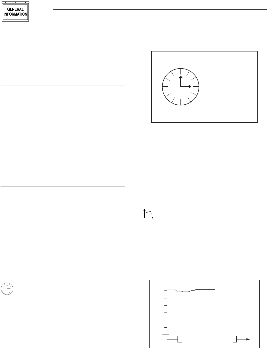
TIME & DATE MENU
Time
There is a live, updating display of the current time, day,
and date shown on the menu icon page (Figure 17).
Figure 17 — Time & Date Menu
MENU
TIME
AND
DATE
04/17/07
Monday
15:25:03
Time
Selecting this menu permits setting the clock to the correct time,
day and date. This will only need to be done the first time the base
station is powered up, or to correct any small errors in the time.
Use the two arrow keys to set the correct time, day and date.
The separate clock in the generator is synchronized to this clock
when it is changed. Synchronization is checked and corrected, if
necessary, every ten minutes. If the clock or date is changed at the
generator, the clock at the base station is also changed automati-
cally (The two clocks are linked together and can be changed at
either end of the link).
GRAPH MENU
t
The Graph menu permits graphing data in real time on a
rolling screen (Figure 18). Choose what to graph from the
following list:
Utility Voltage•
Generator Battery Volts•
Generator RPM (in units of RPM x 100)•
The display is updated with a new point every 200ms so it takes
about 25 seconds to scroll the whole screen. However new data is
only read from the generator every two (2) seconds.
Figure 18 — Sample Graph of Engine RPM
36
30
24
18
Engine RPM t
Wireless Display System
11
Wireless Display System
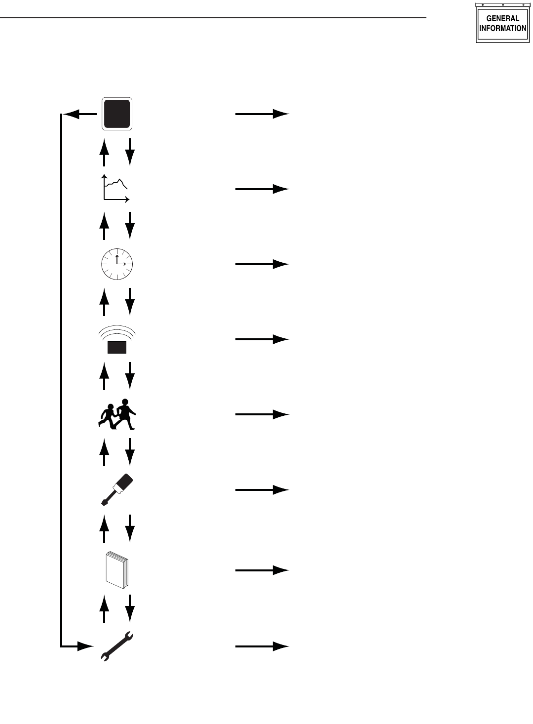
MENU MAP
T
+
STATUS Display Status Information
TEST
1. Normal Start
2. Start & Transfer
3. Low Speed Start
4. Stop Generator
L
O
GHISTORY Display the History Log
SETTINGS
1. Adjust Contrast
2. Clear History Log
3. Add Me to Network
EXERCISE Set an Exercise Time and Day
Select Low or High Speed Exercise
RADIO
1. Show Radio Information
2. Change Channels
3. Reset Radio
4. Add New Display
5. Test Radio Link
Time
TIME &
DATE Set the Clock and Calendar
t
GRAPH
Graph - Generator Battery Voltage
- Generator RPM
- Current
- Utility Voltage
Up Down
12
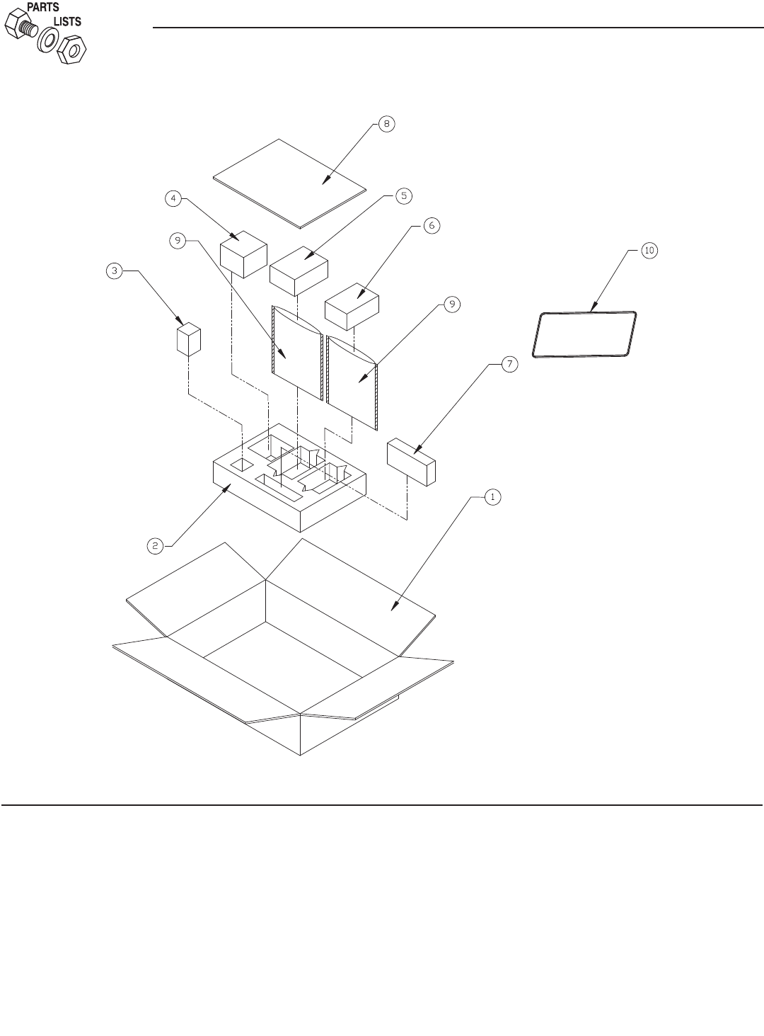
Exploded Views and Parts Lists
Fadd Assembly – Drawing No. 0G8855-B
ITEM PART NO. QTY. DESCRIPTION
1 0G7127 1 CARDBOARD BOX
2 0G7128 1 PE-FOAM
3 0G7161 3 BATTERY, AAA
4 0G4904 1 AC ADAPTOR, 120Vac / 5Vdc
5 0G6020 1 HOME SIDE RF ANNUNCIATOR
6 0G6019 1 GENERATOR SIDE RF ANNUNCIATOR
7 0G8856 1 HARN PCB-RF MOD
8 0G8898 1 MANUAL WIRELESS DSP SYS 2008
9 0G7130 2 STATIC SHIELDING BAG 200 X 140 X 0.08t
10 0G7092 1 GASKET 2.0 X 4.0 X 313
11 084543A 2 SCREW PPPH 3 X 12MM
12 052777 2 WASHER FLAT M3

13
Wireless Display System
13

Part No. 0G8898 Revision E (01/15/09) Printed in U.S.A.
GENERAC POWER SYSTEMS “180 DAY” LIMITED WARRANTY
FOR WIRELESS REMOTE MONITOR (FOR AIR-COOLED GENERATORS)
For a period of 180 days from the date of original sale, Generac Power Systems, Inc. (Generac) warrants its wireless remote monitor will
be free from defects in materials and workmanship for the items and period set forth below. Generac will, at its option, repair or replace any
part which, upon examination, inspection and testing by Generac or a Generac Authorized Warranty Service Dealer, is found to be defec-
tive. Any equipment that the purchaser/owner claims to be defective must be returned to and examined by the nearest Generac Authorized
Warranty Service Dealer. All transportation costs under the warranty, including return to the factory, are to be borne and prepaid by the pur-
chaser/owner. This warranty applies only to Generac wireless remote monitor and is not transferable from original purchaser.
WARRANTY SCHEDULE
Consumer applications are warranted for 180 days.
CONSUMER APPLICATION
180 DAY - 100% (one hundred percent) coverage on Labor and Part(s) listed (proof of purchase is required):
The warranty period begins on the date of purchase by the first retail end user, and continues for the period of time stated above.
“Consumer Application” means personal residential household use by a retail consumer. No other use is warranted.
SAVE YOUR PROOF OF PURCHASE RECEIPT. IF YOU DO NOT PROVIDE PROOF OF THE INITIAL PURCHASE DATE AT THE TIME WARRANTY
SERVICE IS REQUESTED, THE MANUFACTURING DATE OF THE PRODUCT WILL BE USED TO DETERMINE THE WARRANTY PERIOD.
All warranty expense allowances are subject to the conditions defined in Generac’s Warranty Policies, Procedures and Flat Rate Manual.
THIS WARRANTY SHALL NOT APPLY TO THE FOLLOWING:
• Costs of normal maintenance, adjustments and cleaning.
• Normal wear and tear.
• Repairs or diagnostics performed by individuals other than Guardian/Generac authorized dealers not authorized in writing by Generac Power
Systems.
• Failures due, but not limited, to normal wear and tear, accident, misuse, abuse, negligence or improper use.
• Failures caused by any act of God and other force majeure events beyond the manufactures control.
• Damage related to rodent and/or insect infestation.
• Products that are modified or altered in a manner not authorized by Generac in writing.
• Any incidental, consequential or indirect damages caused by defects in materials or workmanship, or any delay in repair or replacement of the
defective part(s).
• Failure due to misapplication.
• Telephone, cellular phone, facsimile, internet access or other communication expenses.
• Living or travel expenses of person(s) performing service, except as specifically included within the terms of a specific unit warranty period.
• Expenses related to “customer instruction” or troubleshooting where no manufacturing defect is found.
• Overnight freight costs for replacement part(s).
• Overtime, holiday or emergency labor.
• Operating batteries, seals, connectors, fuses, mounting hardware and/or equipment.
THIS WARRANTY IS IN PLACE OF ALL OTHER WARRANTIES, EXPRESSED OR IMPLIED. SPECIFICALLY, GENERAC MAKES NO OTHER
WARRANTIES AS TO THE MERCHANTABILITY OR FITNESS FOR A PARTICULAR PURPOSE. Any implied warranties which are allowed
by law, shall be limited in duration to the terms of the express warranty provided herein. Some states do not allow limitations on how
long an implied warranty lasts, so the above limitation may not apply to you. GENERAC’S ONLY LIABILITY SHALL BE THE REPAIR OR
REPLACEMENT OF PART(S) AS STATED ABOVE. IN NO EVENT SHALL GENERAC BE LIABLE FOR ANY INCIDENTAL OR CONSEQUENTIAL
DAMAGES, EVEN IF SUCH DAMAGES ARE A DIRECT RESULT OF GENERAC’S NEGLIGENCE.
Some states do not allow the exclusion or limitation of incidental or consequential damages, so the above limitation may not apply to you.
This warranty gives you specific legal rights. You also have other rights from state to state.
GENERAC POWER SYSTEMS, INC.
P.O. BOX 8 • Waukesha, WI 53187
Ph: (888) GENERAC (436-3722) • Fax: (262) 544-4851
To locate the nearest Authorized Dealer visit our website at www.generac.com
Part No. 0H1608 Revision A (11/25/08) Printed in U.S.A.