Generac 1675 0 User Manual PRESSURE WASHER Manuals And Guides L0403257
GENERAC Power Washer, Gas Manual L0403257 GENERAC Power Washer, Gas Owner's Manual, GENERAC Power Washer, Gas installation guides
User Manual: Generac 1675-0 1675-0 GENERAC PRESSURE WASHER - Manuals and Guides View the owners manual for your GENERAC PRESSURE WASHER #16750. Home:Lawn & Garden Parts:Generac Parts:Generac PRESSURE WASHER Manual
Open the PDF directly: View PDF ![]() .
.
Page Count: 36
/
Pressure Washer Owner's Manual
Questions? Help is just a moment away!
Call: Generac Generator Helpline - 1-800-270-1408 M-F 8-5 CT
Web: www.generac-portables.com or www.briggsandstratton.com
Model No. 1675-0 (2,400 PSiPressure Washer) Manual No. 190164GS Revision 2 (08/27/2002)
TABLE OF CONTENTS
Safety Rules.................................. 2-3
Know Your PressureWasher ...................... 4
Assembly.................................... 5-8
Operation .................................. 8-II
Product Specifications........................... I I
Maintenance ............................... 12-14
Storage...................................... 14
Troubleshooting ............................... 15
Replacement Parts........................... 16-19
Warranty ............................... Last Page
EQUIPMENT
DESCRIPTION
Read this manual carefully and become familiar
with your pressure washer. Know its applications,
its limitations and any hazards involved.
Everyeffort has been made to ensure that informationin
this manual is accurate and current However, Generac
reservesthe right to change,alter or otherwise improve the
)roduct andthis document at any time without prior notice.
WARNING
The engine exhaust from this product contains
chemicals known to the State of California to cause
cancer, birth defects, or other reproductive harm.
the State of California a spark arrester is required by law
Section 4442 of the California Public ResourcesCode).
)ther states may havesimilar laws.Federal lawsapply on
Federallands.If you equip the muffler with a spark arrestel
t must be maintained ineffective working order.
SAFETY RULES
The safety alert symbol (_.) is used with a signal word
(DANGER, CAUTION, WARNING), a pictorial and/or a
safety messageto alert you to hazards. DANGER
indicates a hazard which, if not avoided, will result in death
or serious injury.WARNING indicatesa hazard which, if
not avoided, could result in death or serious injury.
CAUTION indicates a hazard which, if not avoided, might
result in minor or moderate injury.CAUTION, when
used without the alert symbol, indicates a situation that
could result in equipment damage.Follow safety messages
to avoid or reduce the risk of injury or death.
WARNING
WHEN ADDING FUEL
Turnpressure washer OFF and let it cool at [east2 minutes
before removing gascap.
Fill fuel tank outdoors.
Do not overfill tank. Allow spacefor fuel expansion.
Keep gasoline away from sparks, open flames, pilot lights, heat,
and other ignitionsources.
Do not lighta cigarette or smoke.
eVHEN OPERATING EQUIPMENT
Do not tip engine or equipment at anglewhich causes
gasolineto spill
Do not spray flammable liquids.
'HEN TRANSPORTING OR REPAIRING EQUIPMENT
Transport/repair with fuel tank EMPTY or with fuel shutoff
valve OrE
eVHEN STORING GASOLINE OR EQUIPMENT WITH
FUEL IN TANK
Store awayfrom furnaces, stoves, water heaters, clothes
dryers or other appliancesthat have pilot lightor other
ignitionsource becausethey can ignite gasoline vapors.
WARNING
Keepwater sprayawayfrom electric wiring or fatalelectric
shockmayresult.
WARNING
Never aim the spray gun at people, animals or plants.
Do not allow CHILDREN to operate the pressure washer.
Never repair high pressure hose. Replace it.
/
2

,_ WARNING
Keep spray nozzle between 8 to 24 inches away from cleaning
surface.
Beextremely careful if you must usethe pressure washer from
a [adder,scaffolding or any other relatively unstable location.
The cleaning area should have adequate slopes and drainage to
reduce the possibility of a fail due to slippery surfaces.
Operate this unit on a stable surface.
,_ WARNING
Do not wear loose clothing, jewelry or anything that may be
caught in the starter or other rotating parts.
Tie up long hair and remove jewelry.
,_ WARNING
Always wear eye protection when you usethis equipment or
when you are in the vicinity where the equipment is in use.
,_ DANGER
Operate pressure washer ONLY outdoors.
Use a respirator or mask whenever there is a chance that
vapors may be inhaled.
Readall instructions with mask so you are certain the maskwi[[
provide the necessaryprotection againstinhaling harmful vapors.
,_ WARNING
Do not touch hot surfaces.
Allow equipment to cool before touching.
,_ WARNING
Disconnect the spark plug wire from the spark plug and place
the wire where it cannot contact spark plug.
,_ CAUTION
Do not tamper with governed speed.
Do not operate the pressure washer abovethe rated pressure.
CAUTION
Do not point spray gun at glasswhen in the jet spray mode.
Never aim the spray gun at plants.
/
3
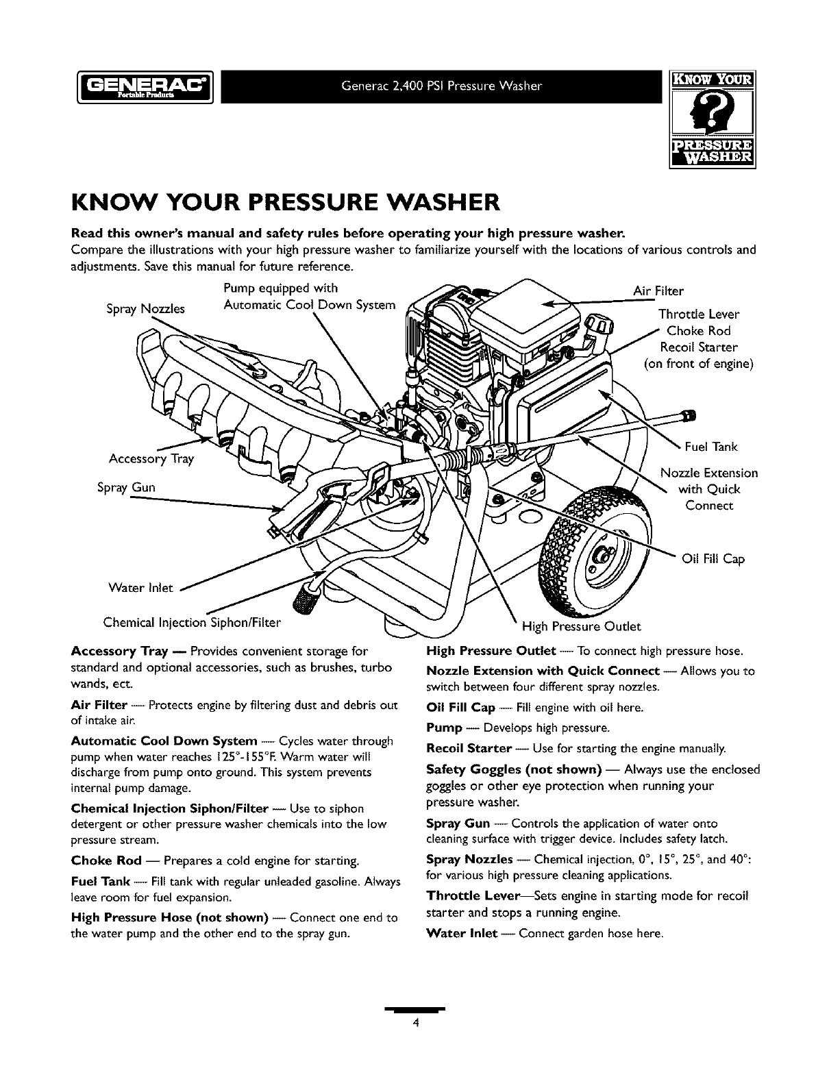
KNOW YOUR PRESSURE WASHER
Read this owner's manual and safety rules before operating your high pressure washer.
Compare the illustrations with your high pressure washer to familiarize yourself with the locations of various controls and
adjustments. Savethis manual for future reference.
Pump equipped with
Spray Nozzles Automatic Coot Down System
Air Filter
Throttle Lever
Choke Rod
Starter
(on front of engine)
Accessory Tray
Spray Gun
Tank
Nozzle Extension
with Quick
Connect
Fill Cap
Chemical Injection Siphon/Filter
Accessory Tray _ Provides convenient storage for
standard and optional accessories, such as brushes, turbo
wands, ect.
Air Filter -- Protects engine by filtering dust and debris out
of intake air.
Automatic Cool Down System -- Cycles water through
pump when water reaches 125% i 55°E Warm water will
discharge from pump onto ground. This system prevents
internal pump damage.
Chemical Injection Siphon/Filter -- Use to siphon
detergent or other pressure washer chemicals into the low
pressure stream.
Choke Rod -- Prepares a cold engine for starting.
Fuel Tank -- Fill tank with regular unleaded gasoline. Always
leave room for fuel expansion.
High Pressure Hose (not shown) -- Connect one end to
the water pump and the other end to the spray gun.
High Pressure Outlet
High Pressure Outlet -- To connect high pressure hose.
Nozzle Extension with Quick Connect -- Allows you to
switch between four different spray nozzles.
Oil Fill Cap -- Fill engine with oil here.
Pump -- Develops high pressure.
Recoil Starter -- Use for starting the engine manually.
Safety Goggles (not shown) -- Always use the enclosed
goggles or other eye protection when running your
pressure washer.
Spray Gun -- Controls the application of water onto
cleaning surface with trigger device, includes safety latch.
Spray Nozzles -- Chemical injection, 0°, 15°, 25 °, and 40°:
for various high pressure cleaning applications.
Throttle Lever_Sets engine in starting mode for recoil
starter and stops a running engine.
Water Inlet -- Connect garden hose here.
/
4
IMPORTANT: Read entire owner's manual before you
attempt to assembleor operate your new pressure washer.
REMOVE PRESSURE
WASHER FROM
CARTON
•Remove the parts bag packedwith pressure washer.
• Slice two corners at the end of carton from top to
bottom so the panel can be folded down fiat, then
remove all packing material.
• Roll pressure washer out of carton.
Carton Contents
Items in the carton include:
• Main Unit
Safety Goggles
Handle
PlasticAccessory Tray
High Pressure Hose
Spray Gun
Nozzle Extension with Quick Connect Fitting
Oit Bottle
Parts Bag(which includesthe following):
Owner's Manual
EngineManual
EngineWarranty Card
EmissionsControl Warranty Card
Owner's Registration Card
Bagcontaining5 mult_olored Quick Connect Nozzles
Maintenance Kit
Handle Fastening Hardware Kit (which includes):
Carriage Bott
"L" Bolt
Plastic Knobs (2)
"J" Hook
Chemical Hose Clip
Self Tapping Screws (5)
If any of the above parts are missing or damaged,catl the
pressure washer helpline at 1-800-270-1408.
PREPARING PRESSURE
WASHER FOR USE
If you have any problems with the assemblyof your
pressure washer or if parts are missing or damaged,call the
pressure washer helpline at 1-800-270-1408.
To prepare your pressure washer for operation, you
will need to perform these tasks:
• Fitl out and send in registration card.
• Attach accessory tray to handle, then attach handle to
main unit.
Add oil to engine crankcase.
Add fuel to fuel tank.
Connect high pressure hose to spraygun and pump.
Connect water supply to pump.
Attach nozzte extension to spray gun.
Select/attach quick connect nozzle to nozzle extension.
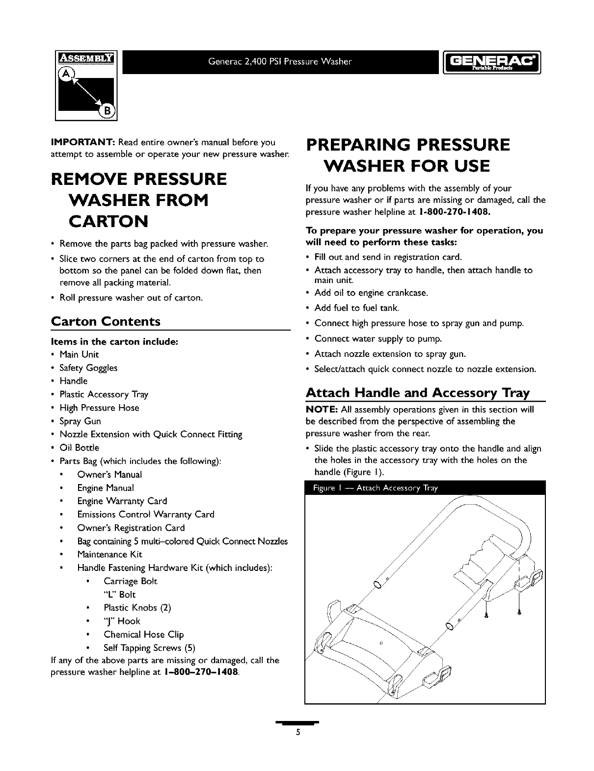
Attach Handle and Accessory Tray
NOTE: AIt assemblyoperations given in this section will
be described from the perspective of assemblingthe
pressure washer from the rear.
• Slide the plastic accessory tray onto the handle and align
the holes in the accessory tray with the holes on the
handle (Figure I).
I5
•Secure tray to handle with self tapping screws using a
#2 phillips screwdriver. Ensurescrews are tight but not
crushing the plastic accessory tray.
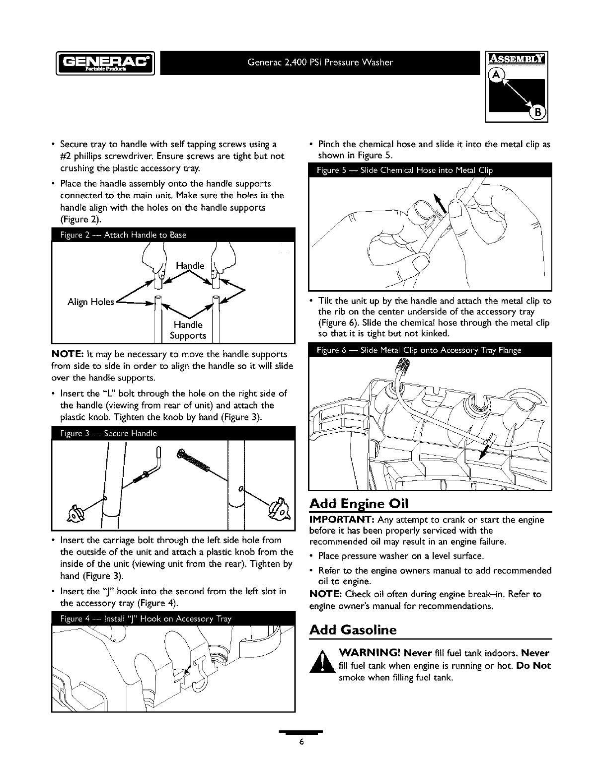
• Placethe handle assembly onto the handle supports
connected to the main unit. Make sure the holes in the
handle alignwith the holes on the handle supports
(Figure 2).
Atig
Handle
Supports
NOTE: It may be necessaryto move the handle supports
from side to side in order to align the handle so it will slide
over the handle supports.
• Insert the "L" bolt through the hole on the right side of
the handle (viewing from rear of unit) and attach the
plastic knob. Tighten the knob by hand (Figure 3).
: .
S'-
•Insert the carriage bolt through the left side hole from
the outside of the unit and attach a plastic knob from the
inside of the unit (viewing unit from the rear). Tighten by
hand (Figure 3).
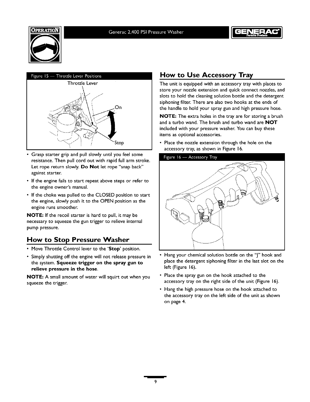
• Insert the "J"hook into the second from the left slot in
the accessory tray (Figure 4).
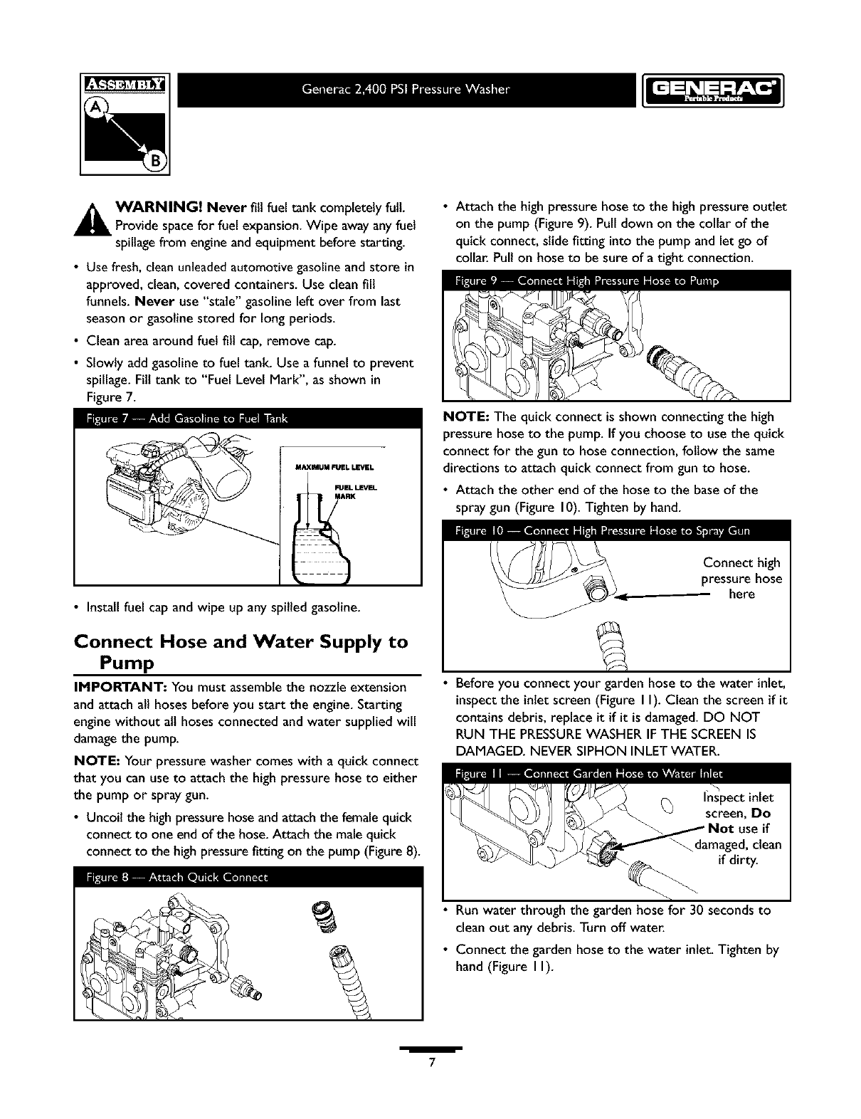
• Pinch the chemical hose and slide it into the metal clip as
shown in Figure 5.
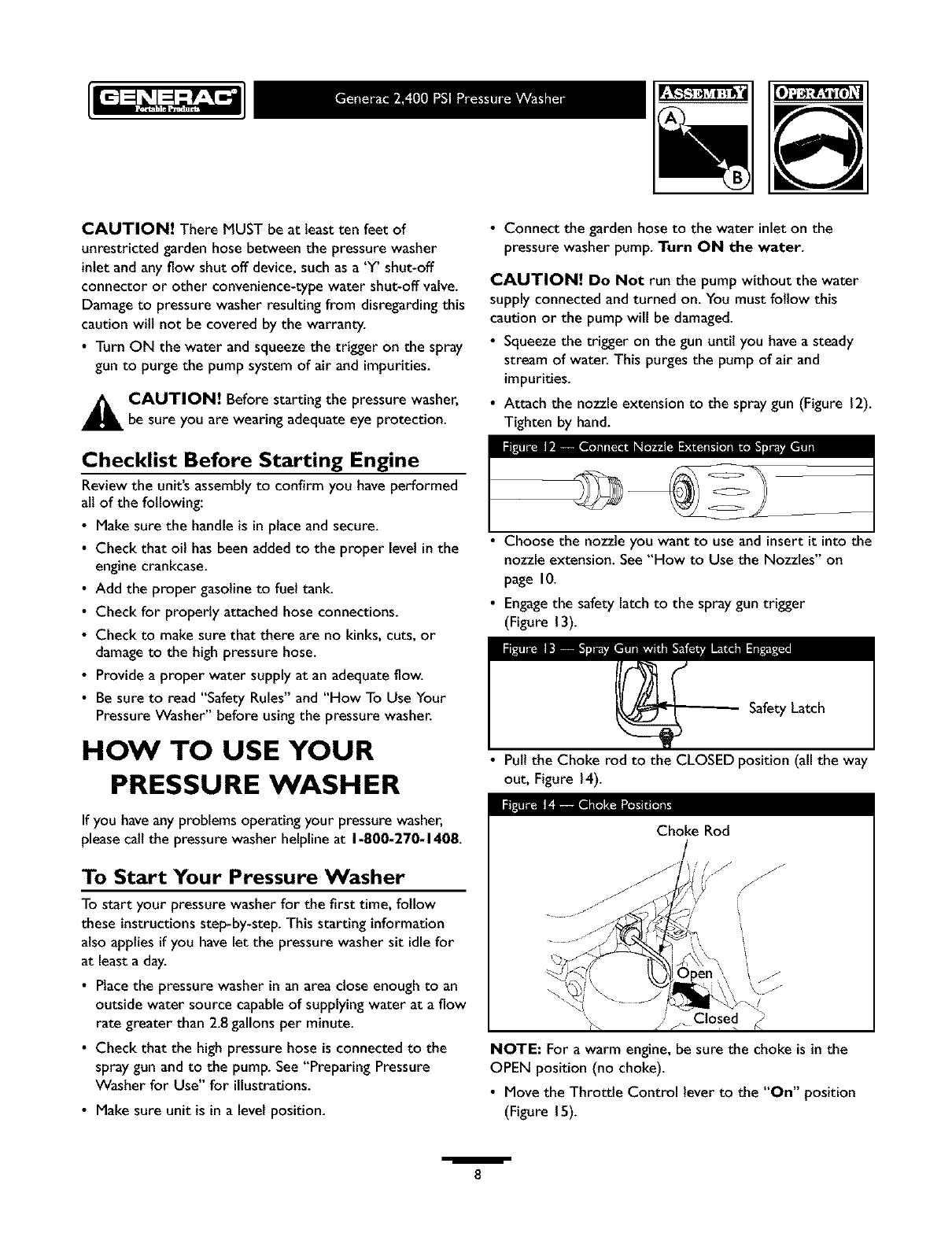
•Tilt the unit up by the handle and attach the metal clip to
the rib on the center undersideof the accessory tray
(Figure 6). Slide the chemical hose through the metal clip
so that it is tight but not kinked.
Add Engine Oil
IMPORTANT: Any attempt to crank or start the engine
before it has been properly serviced with the
recommended oil may result in an engine failure.
• Place pressure washer on a levelsurface.
• Refer to the engine owners manual to add recommended
oil to engine.
NOTE: Check oil often during engine break-in. Refer to
engine owner's manual for recommendations.
Add Gasoline
_IL WARNING! Never fill fuel tank indoors. Never
fill fuel tank when engine is running or hot. Do Not
smoke whenfilling fuel tank.
/6
A ARNING! Never fill fuel tank completely full.
Provide spacefor fuel expansion.Wipe awayanyfuel
spillagefrom engine and equipment before starting.
•Use fresh, clean unleadedautomotive gasolineand store in
approved, clean, covered containers. Use clean fill
funnels. Never use "stale" gasoline left over from last
season or gasoline stored for longperiods.
• Clean area around fuel flit cap, remove cap.
• Slowly add gasoline to fuel tank. Use a funnel to prevent
spillage. Fitl tank to "Fuel Level Mark", as shown in
Figure 7.
MAXIMUM FUEL LEVEL
•Attach the high pressure hose to the high pressure outlet
on the pump (Figure 9). Pulldown on the collar of the
quick connect, slide fitting into the pump and let go of
collar. Pull on hose to be sure of a tight connection.
[] !
NOTE: The quick connect is shown connecting the high
pressure hose to the pump. Ifyou choose to use the quick
connect for the gun to hose connection, follow the same
directions to attach quick connect from gun to hose.
•Attach the other end of the hose to the base of the
spray gun (Figure 10). Tighten by hand.
• Install fuel cap and wipe up any spilled gasoline.
Connect Hose and Water Supply to
Pump
IMPORTANT: You must assemblethe nozzle extension
and attach alt hoses before you start the engine. Starting
engine without alt hoses connected and water supplied will
damagethe pump.
NOTE: Your pressure washer comes with a quick connect
that you can use to attach the high pressure hose to either
the pump or spraygun.
• Uncoil the high pressure hose and attach the femalequick
connect to one end of the hose. Attach the male quick
connect to the high pressurefitting on the pump (Figure 8).
\\
• Before you connect your garden hose to the water inlet,
inspectthe inlet screen (Figure I I). Clean the screen if it
contains debris, replace it if it isdamaged. DO NOT
RUN THE PRESSUREWASHER IF THE SCREEN IS
DAMAGED. NEVER SIPHON INLET WATER.
• Run water through the garden hose for 30 seconds to
clean out any debris. Turn off water.
• Connect the garden hose to the water inlet. Tighten by
hand (Figure II).
/
7
CAUTION! There MUST be at least ten feet of
unrestrictedgarden hose between the pressure washer
inlet and any flow shut off device, such as a 'Y' shut-off
connector or other convenience-type water shut-ofF valve.
Damage to pressure washer resulting from disregarding this
caution will not be covered by the warranty.
•Turn ON the water and squeeze the trigger on the spray
gun to purge the pump system of air and impurities.
_AUTION! Before starting the pressure washer,
be sure you are wearingadequate eye protection.
Checklist Before Starting Engine
Review the unit's assemblyto confirm you have performed
alt of the following:
• Make sure the handle is in place and secure.
• Check that oit has been added to the proper levelinthe
engine crankcase.
• Add the proper gasoline to fuel tank.
• Check for properly attached hose connections.
• Check to make sure that there are no kinks, cuts, or
damageto the high pressure hose.
• Provide a proper water supply at an adequate flow.
• Be sure to read "Safety Rules" and "How To Use Your
PressureWasher" before using the pressure washer.
HOW TO USE YOUR
PRESSURE WASH ER
If you haveany problems operating your pressurewasher,
pleasecatl the pressure washer helpline at 1-800-270-1408.
To Start Your Pressure Washer
To start your pressure washer for the first time, follow
these instructionsstep-by-step. This starting information
also applies if you have let the pressure washer sit idle for
at leasta day.
• Placethe pressure washer in an area close enough to an
outside water source capable of supplying water at a flow
rate greater than 2.8gallons per minute.
• Check that the high pressure hose is connected to the
spray gun and to the pump. See"Preparing Pressure
Washer for Use" for illustrations.
• Make sure unit is in alevel position.
• Connect the garden hose to the water inlet on the
pressure washer pump. Turn ON the water.
CAUTION! Do Not run the pump without the water
supply connected and turned on. You must follow this
caution or the pump will be damaged.
• Squeezethe trigger on the gun until you have a steady
stream of water. This purges the pump of air and
impurities.
• Attach the nozzle extension to the spray gun (Figure 12).
Tighten by hand.
Choose the nozzle you want to use and insert it into the
nozzle extension. See "How to Use the Nozzles" on
page I0.
• Engagethe safety latchto the spray gun trigger
(Figure 13).
Safety Latch
• Putl the Choke rod to the CLOSED position (all the way
out, Figure 14).
Choke Rod
/
/
_' /' j_ Closed
NOTE: For a warm engine, be sure the choke is in the
OPEN position (no choke).
• Move the Throttle Control leverto the "On" position
(Figure 15).
I8
Throttle Lever
Stop
•Grasp starter grip and pull slowly until you feel some
resistance. Then pull cord out with rapid full arm stroke.
Let rope return slowly. Do Not let rope "snap back"
againststarter.
• If the engine fails to start repeat above steps or refer to
the engine owner's manual.
• If the choke was pulled to the CLOSED position to start
the engine, slowly push it to the OPEN position as the
engine runs smoother.
NOTE: If the recoil starter is hard to pull, it may be
necessaryto squeezethe gun trigger to relieve internal
pump pressure.
How to Stop Pressure Washer
• Move Throttle Control lever to the 'Stop' position.
• Simply shutting off the enginewill not release pressure in
the system. Squeeze trigger on the spray gun to
relieve pressure in the hose.
NOTE: A small amount of water will squirt out when you
squeezethe trigger.
How to use Accessory Tray
The unit is equipped with an accessory tray with placesto
store your nozzle extension and quick connect nozzles, and
slots to hold the cleaning solution bottle and the detergent
siphoning filter. There are also two hooks at the ends of
the handle to hold your spray gun and high pressure hose.
NOTE: The extra holes in the tray are for storing a brush
and a turbo wand. The brush and turbo wand are NOT
included with your pressure washer. You can buy these
items as optional accessories.
• Place the nozzle extension through the hole on the
accessory tray, as shown in Figure 16.
• Hang your chemical solution bottle on the "J"hook and
place the detergent siphoning filter inthe last slot on the
left (Figure 16).
• Place the spray gun on the hook attached to the
accessory tray on the right side of the unit (Figure 16).
• Hang the high pressure hose on the hook attached to
the accessory tray on the left side of the unit as shown
on page4.
/
9
How to Use the Nozzles
_AUTION! Never exchange nozzles without
lockingthe safety latch on the trigger.
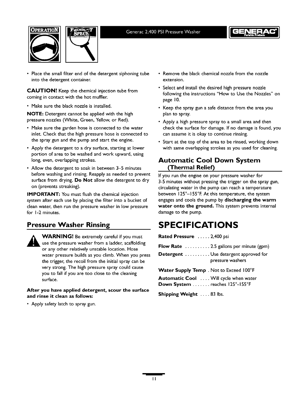
The quick-connect on the nozzle extension allows you to
switch between five different nozzles.The nozzles vary the
spray pattern as shown below (Figure 17).
Follow these instructions to change nozzles:
•Engagethe safety latch on the spray gun.
• Pull back the collar on the quick-connect and pull the
current nozzle off. Store the nozzle in the space
provided on the handles storage panel.
NOTE: For a more gentle rinse, select the white 40° or
green 25°nozzle. To scour the surface, select the yellow
15°or red 0° nozzle. To apply chemical, select the black
nozzle.
• Pull back on the collar,insert the new nozzle and release
the collar. Tug on the nozzle to make sure it is securely
in place.
• For most effective cleaning, keep the spray nozzle
between 8 to 24 inchesaway from the cleaning surface. If
you get the spray nozzle too close, you may damagethe
cleaningsurface.
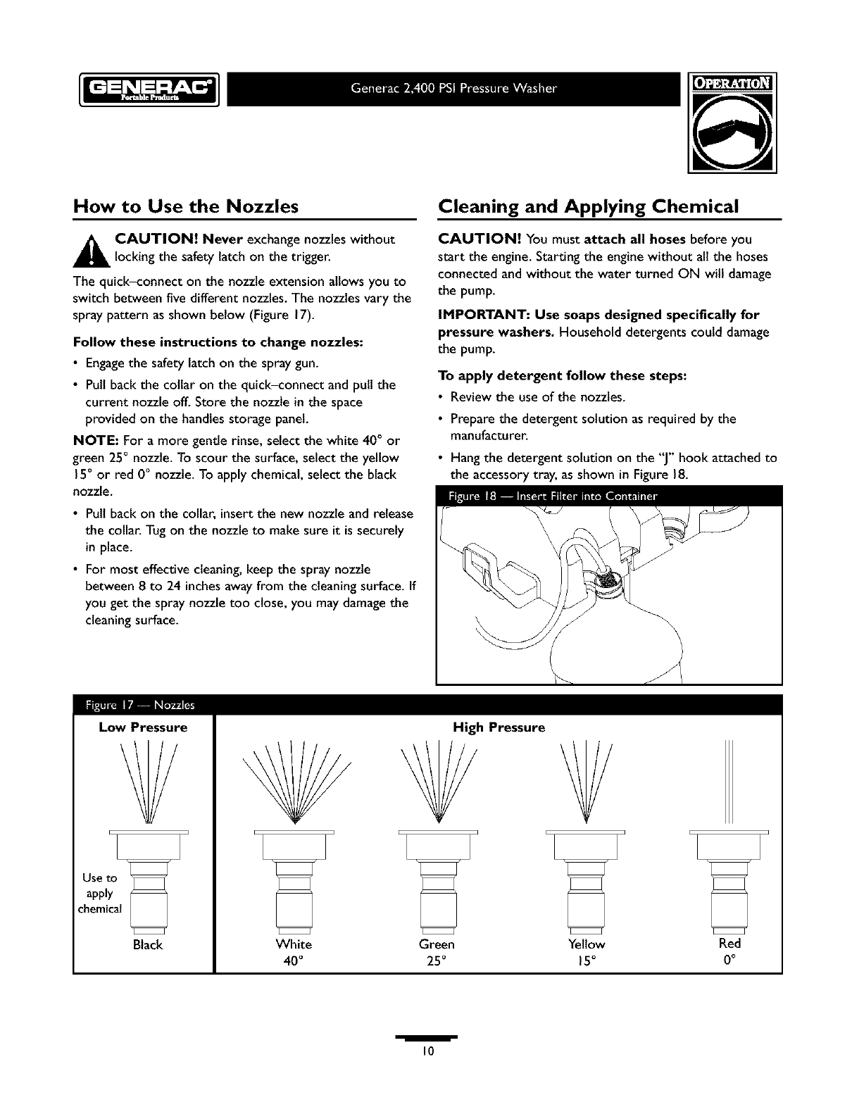
Cleaning and Applying Chemical
CAUTION! You must attach all hoses before you
start the engine. Starting the engine without all the hoses
connected and without the water turned ON will damage
the pump.
IMPORTANT: Use soaps designed specifically for
pressure washers. Household detergents could damage
the pump.
To apply detergent follow these steps:
•Review the use of the nozzles.
• Prepare the detergent solution as required by the
manufacturer.
• Hang the detergent solution on the "J" hook attached to
the accessory tray, as shown in Figure 18.
Low Pressure
Black
High Pressure
Y
White Green Yellow Red
40°25°15° 0°
/
I0
• Placethe small filter end of the detergent siphoning tube
into the detergent container.
CAUTION! Keep the chemical injection tube from
coming in contact with the hot muffler.
• Make sure the black nozzle is installed.
NOTE: Detergent cannot be applied with the high
pressure nozzles (White, Green, Yellow, or Red).
• Make sure the garden hose is connected to the water
inlet. Check that the high pressure hose is connected to
the spraygun and the pump and start the engine.
• Apply the detergent to a dry surface, starting at lower
portion of area to be washed and work upward, using
long, even, overlapping strokes.
• Allow the detergent to soak in between 3-5 minutes
before washing and rinsing. Reapplyas needed to prevent
surface from drying. Do Not allow the detergent to dry
on (prevents streaking).
IMPORTANT: You must flush the chemical injection
system after each use by placing the filter into a bucket of
clean water, then run the pressure washer in low pressure
for I-2 minutes.
Pressure Washer Rinsing
_ ARNING! Be extremely careful if you must
use the pressure washer from a ladder, scaffolding
or any other relatively unstable location. Hose
water pressure builds as you climb. When you press
the trigger, the recoil from the initial spray can be
very strong. The high pressure spray could cause
you to fall if you are too close to the cleaning
surface.
After you have applied detergent, scour the surface
and rinse it clean as follows:
• Apply safety latchto spray gun.
• Remove the black chemical nozzle from the nozzle
extension.
• Select and installthe desired high pressure nozzle
following the instructions "How to Use the Nozzles" on
page 10.
• Keep the spray gun a safedistance from the area you
plan to spray.
• Apply a high pressure spray to a small area and then
check the surface for damage.If no damage is found, you
can assume it is okay to continue rinsing.
• Start at the top of the area to be rinsed, working down
with same overlapping strokes as you used for cleaning.
Automatic Cool Down System
(Thermal Relief)
If you run the engine on your pressure washer for
3-5 minutes without pressingthe trigger on the spray gun,
circulating water in the pump can reach a temperature
between 125°-155°E At this temperature, the system
engagesand cools the pump by discharging the warm
water onto the ground. This system prevents internal
damage to the pump.
SPECIFICATIONS
Rated Pressure ..... 2,400 psi
Flow Rate .......... 2.5 gallons per minute (gpm)
Detergent .......... Use detergent approved for
pressure washers
Water Supply Temp. Not to Exceed 100°F
Automatic Cool .... Will cycle when water
Down System ....... reaches 1250-155°F
Shipping Weight .... 83 lbs.
/
II
GENERAL MAINTENANCE
RECOMMENDATIONS
The pressure washer warranty does not cover items that have
been subjected to operator abuse or negligence. To receive
full value from the warranty, the operator must maint3in the
high pressure washer as instructed in this manual.
• Some adjustments will need to be made periodically to
properly maintain your high pressure washer. Check the
spray gun and adjustable nozzle extension assembly for wear.
•All maintenance in this manual and the engine owner's
manual should be made at {east once each season.
• Once a year you should clean or replace the spark plug,
clean or replace the air filter. A new spark plug and clean
air filter assure proper fuel-alr mixture and help your
engine run better and last longer. Please refer to your
engine owner's manual for more details.
BEFORE EACH USE
•Check engineoit level.
Check water inlet screen for damage.
Check in-line filter for damage.
Check high pressure hose for leaks.
Check detergent siphoning tube and filter for damage.
Check spraygun and nozzle extension assemblyfor leaks.
Rinseout garden hose to flush out debris before
connecting to pressure washer.
PRESSURE WASH ER
MAINTENANCE
Check and Clean Inlet Screen
Examinethe screen on the water inlet.Clean it if the
screen is clogged or replace it if screen is damaged.
Check High Pressure Hose
The high pressure hose can develop leaks from wear,
kinking, or abuse. Inspectthe hose each time before using
it. Check for cuts, leaks, abrasions or bulgingof cover,
damage or movement of couplings. If any of these
conditions exist, replace the hose immediately.
_AUTION! Water spraying from a leak is
capable of injectingmaterial into skin. Inspecthose
each time before using it_ Never repair a high
pressure hose. Replace it with another hose that
exceeds the maximum pressure rating of your
pressure washer.
Check Detergent Siphoning Tube
Examine the filter on the detergent tube and clean if
clogged. The tube should fit tightly on the barbed fitting.
Examine the tube for leaksor tears. Replacethe filter or
tube if either is damaged.
Cleaning Detergent Siphoning Tube
If you used the detergent siphoning tube, you must flush it
with clean water before stopping the engine.
• Placethe chemical injection siphon/filter in a bucket full
of clean water.
• Attach the black low pressure nozzle.
• Flushfor I-2 minutes.
• Shut off the engine.
IMPORTANT: Simply shutting OFF engine will not
release pressure in the system.When the engine has
shut down, squeeze the trigger on the spray gun to
relieve the pressure in the hose.
Check Gun and Nozzle Extension
Examine the hose connection to the spray gun and make
sure it is secure. Test the trigger by pressing it and making
sure it "springs back" into place when you release it. Put
the safety latch in the ON position and test the trigger. You
should not be able to press the trigger.
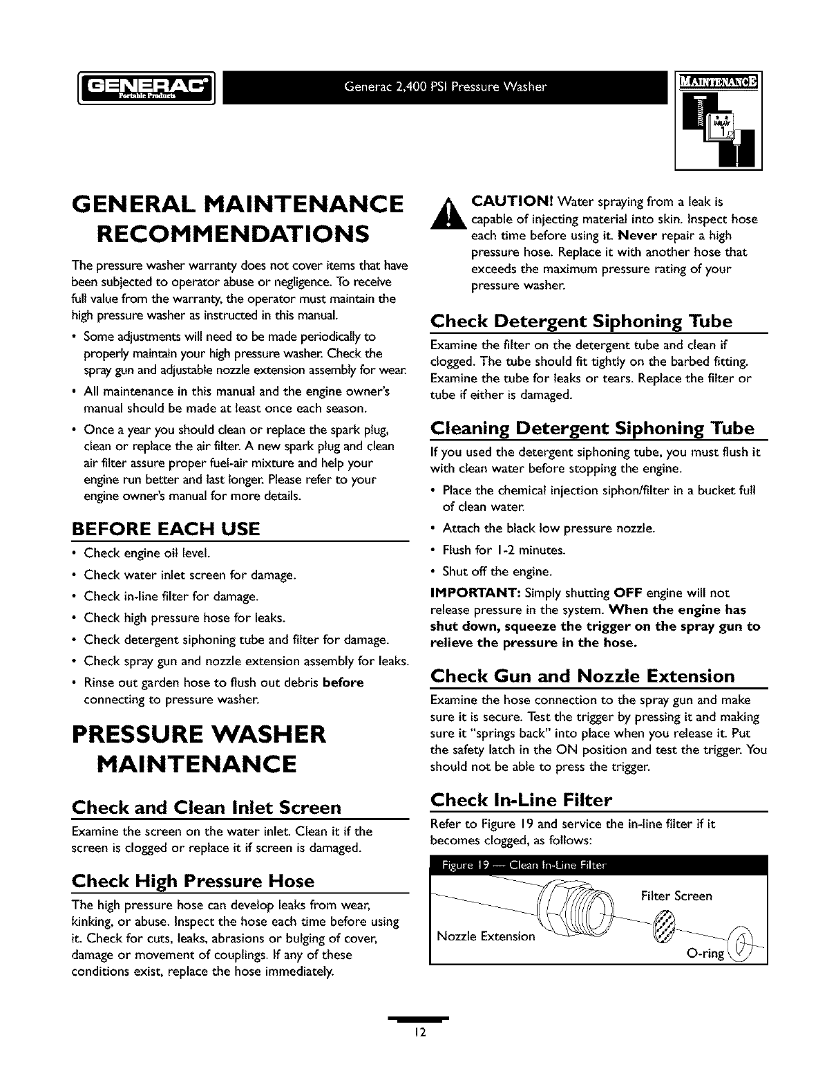
Check In-Line Filter
Refer to Figure 19 and service the in-linefilter if it
becomes clogged, as follows:
Nozzle Extension
/
12
I.
2.
.
Detach spray gun and nozzle extension from high
pressure hose. Detach nozzle extension from spray
gun and remove o-ring and screen from nozzle
extension. Flushthe screen, spraygun, and adjustable
nozzle extension with clean water to clear debris.
If the screen is damaged,the o-ring kit contains a
replacement in-llne filter screen and an o-ring. If
undamaged,reuse screen.
Placethe in-line filter screen into the threaded end of
the nozzle extension. Direction does not matter. Push
the screen in with the eraser end of a pencil until it
rests flat at the bottom of the opening. Takecare to
not bend the screen.
4. Placethe o-ring into the recess. Pushthe o-ring snugly
againstthe in-line filter screen.
5. Assemble the nozzle extension to the spraygun, as
described earlier in this manual.
Purge Pump of Air and
Contaminants
To remove air from the pump, follow these steps:
•Set up the pressure washeras described in "Preparing
PressureWasher For Use". Connect the water supply
and turn water on.
• Pull the trigger on the spraygun and hold.
• When the water supply is steady and constant, engage
the safety latch.
To remove contaminants from the pump, follow
these steps:
• Set up the pressure washer as described in "Preparing
PressureWasher For Use". Connect the water supply
and turn water on.
• Start the engine according to instructionsin "To Start
Your PressureWasher".
• Remove nozzle extension from spray gun.
• Squeezethe trigger on the spray gun and hold.
• When the water supply is steady and constant, engage
the safety latch and reattach the nozzle extension.
Nozzle Maintenance
A pulsing sensation felt while squeezingthe spraygun
trigger may be caused by excessive pump pressure. The
principal cause of excessive pump pressure is a nozzle
clogged or restricted with foreign materials, such as dirt,
etc. To correct the problem, immediatelyclean the nozzle
using the tools includedwith your pressure washer and
follow these instructions:
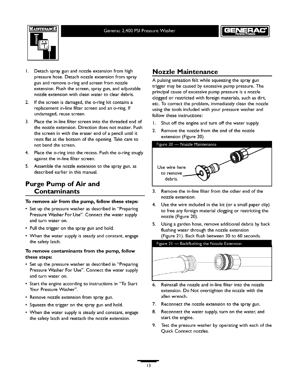
I. Shut off the engineand turn off the water supply.
2. Remove the nozzle from the end of the nozzle
extension (Figure 20).
to remove
debris.
3. Remove the in-linefilter from the other end of the
nozzle extension.
4. Use the wire included in the kit (or a small paper clip)
to free any foreign material clogging or restricting the
nozzle (Figure 20).
5. Usinga garden hose, remove additional debris by back
flushing water through the nozzle extension
(Figure 21). Backflush between 30 to 60 seconds.
J
J
6. Reinstall the nozzle and in-line filter into the nozzle
extension. Do Not overdghten the nozzle with the
allen wrench.
7. Reconnect the nozzle extension to the spray gun.
8. Reconnect the water supply,turn on the water, and
start the engine.
9. Test the pressure washer by operating with each of the
Quick Connect nozzles.
/13
O-Ring Maintenance
Through the normal operation of your pressure washer,
o-rings, which keep the connections of the hoses and spray
gun tight and leak-free, may become worn or damaged.
Provided with your pressure washer is an O-Ring
Maintenance Kit which includes replacement o-rings,
rubber washer and water inlet filter. Refer to the
instruction sheet provided in the kit to service your unit's
o-rings. Note that not all of the parts in the kit will be used
on your unit.
To remove a worn or damaged o-ring:
•Use a small flathead screwdriver to get underneath the
o-ring and pry it off.
ENGINE MAINTENANCE
See the engine owner's manual for instructions on how to
properly maintain the engine.
AAUTION! Avoid prolonged or repeated skin
contact with used motor oil. Used motor oil has
been shown to cause skin cancer in certain
laboratory animals. Thoroughly wash exposed areas
with soap and water.
KEEPOUT OF REACH OF CHILDREN. DON'T
POLLUTE. CONSERVE RESOURCES.RETURN
USED OIL TO COLLECTION CENTERS.
PREPARING THE UNIT
FOR STORAGE
Water should not remain inthe unit for long periods of
time. Sediments or minerals can deposit on pump parts and
"freeze" pump action. If you do not plan to use the pressure
washer for more than 30 days,follow this procedure:
I. Flushdetergent siphoning tube by placing the filter into
a pail of clean water while running pressure washer in
low pressure mode. Flushfor one to two minutes.
2. Shut off the engine and let it cool, then remove high
pressure and garden hoses. Disconnect spark plugwire
from spark plug.
3. Empty the pump of liquids by pulling the engine recoil
handle about 6 times. This should remove most of the
liquid in the pump.
4. Use Generac brand pump saver to prevent corrosion
build up andfreezing of pump.
5. Store unit in a clean, dry area.
Protecting the Pump
To protect the pump from damage caused by mineral
deposits or freezing, use the Generac PumpSaverto treat
pump. This prevents freeze damageand lubricates pistons
and seals.
NOTE: Generac PumpSaver,model number 01559, is
availableas anoptional accessory.It is not includedwith the
pressurewasher.
CAUTION! You must protect your unit from freezing
temperatures. Failure to do so will permanently damage
your pump and render your unit inoperable. Freeze damage
is not covered under warranty.
A CAUTION! Read and follow all cautions and
warnings on the PumpSaver can label. Always wear
eye protection when using PumpSaver.
To use PumpSaver, make sure the pressure washer is
turned off and disconnected from supply water. Read and
follow all instructions and warnings given on the PumpSaver
container.
NOTE: PumpSaver will drip from pump after treatment
and will stain wood and concrete.
NOTE: If PumpSaver is not available, draw RV antifreeze
(non-alcohol) into the pump by pouring the solution into a
3-foot section of garden hose connected to inlet adapter
and pulling recoil handle twice.
STORING THE ENGINE
See the engine owner's manual for instructions on how to
properly prepare the engine for storage.
I
14
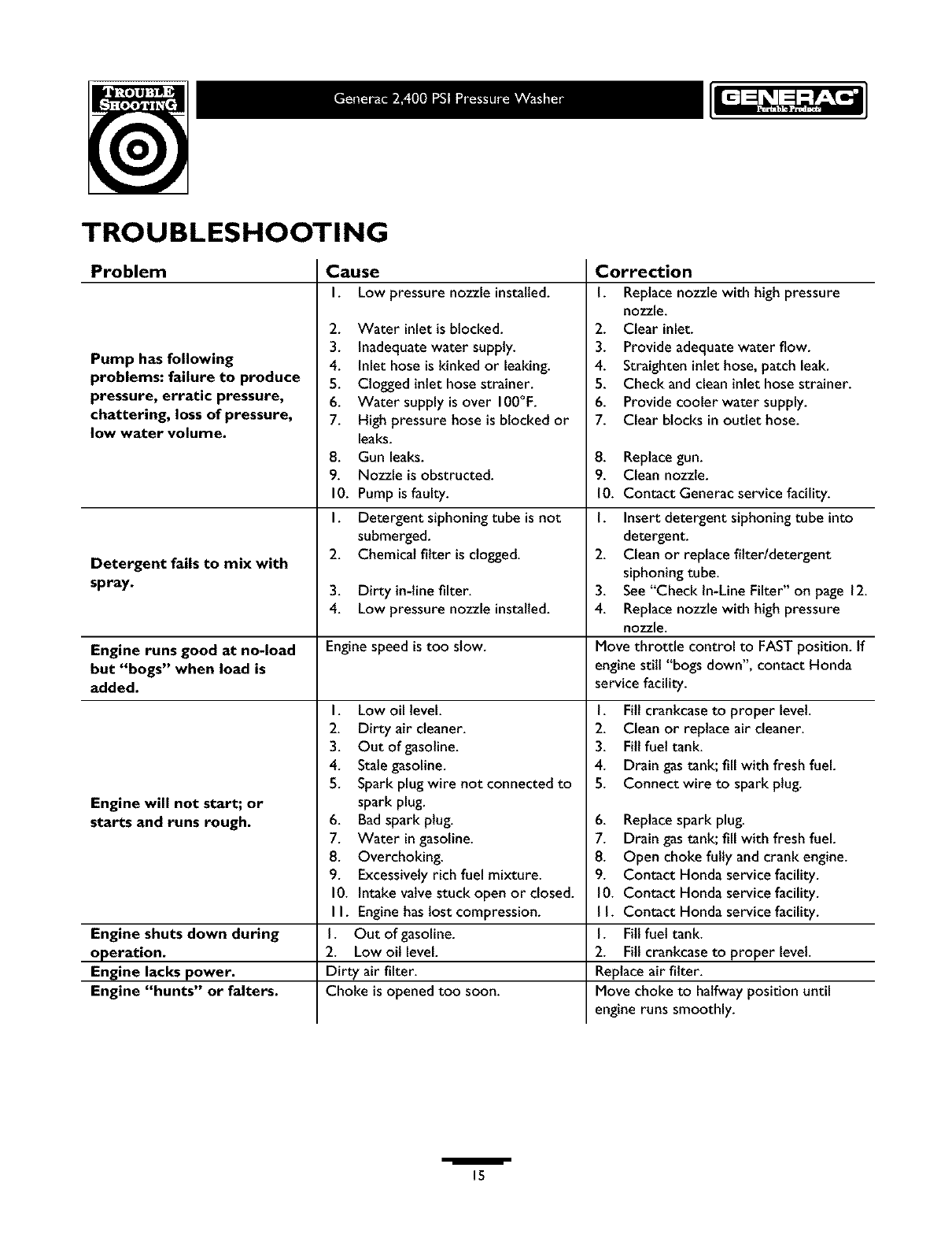
TROUBLESHOOTING
Problem
Pump has following
problems: failure to produce
pressure, erratic pressure,
chattering, loss of pressure,
low water volume.
Detergent fails to mix with
spray.
Cause
I. Low pressure nozzle installed.
2. Water inlet isblocked.
3. Inadequatewater supply.
4. Inlet hose iskinked or leaking.
5. Clogged inlet hose strainer.
6. Water supply isover 100°F.
7. High pressure hose is blocked or
leaks.
8. Gun leaks.
9. Nozzle is obstructed.
10. Pump isfaulty.
I. Detergent siphoning tube is not
submerged.
2. Chemical filter is clogged.
3. Dirty in-line filter.
4. Low pressure nozzle installed.
Engine runs good at no-load Engine speed is too slow.
but "bogs" when load is
added.
Engine will not start; or
starts and runs rough.
Engine shuts down during
operation.
Engine lacks power. Dirty air filter.
Engine "hunts" or falters. Choke is opened too soon.
I. Low oil level.
2. Dirty air cleaner.
3. Out of gasoline.
4. Stalegasoline.
5. Spark plug wire not connected to
spark plug.
6. Badspark plug.
7. Water ingasoline.
8. Overchoking.
9. Excessivelyrich fuel mixture.
10. Intakevatve stuck open or closed.
I I. Enginehas lostcompression.
I. Out of gasoline.
2. Low oil level.
Correction
I. Replacenozzle with high pressure
nozzle.
2. Clear inlet.
3. Provide adequate water flow.
4. Straighten inlet hose, patch leak.
5. Check and clean inlet hose strainer.
6. Provide cooler water supply.
7. Clear blocks in outlet hose.
8. Replacegun.
9. Clean nozzle.
10. Contact Generac service facility.
1. Insert detergent siphoning tube into
detergent.
2. Clean or replace fitter/detergent
siphoning tube.
3. See"Check In-LineFilter" on page 12.
4. Replacenozzle with high pressure
nozzle.
Move throttle control to FASTposition. If
enginestill "bogs down", contact Honda
service facility.
I. Fill crankcaseto proper level.
2. Clean or replace air cleaner.
3. Fill fuel tank.
4. Drain gastank; fill with fresh fuel.
5. Connect wire to spark plug.
6. Replacespark plug.
7. Drain gastank; fill with fresh fuel.
8. Open choke fully andcrank engine.
9. Contact Honda service facility.
10. Contact Honda service facility.
I I. Contact Honda service facility.
I. Fill fuel tank.
2. Fill crankcaseto proper level.
Replace air filter.
Move choke to halfway position until
engine runs smoothly.
I15
2 ¸
_rs
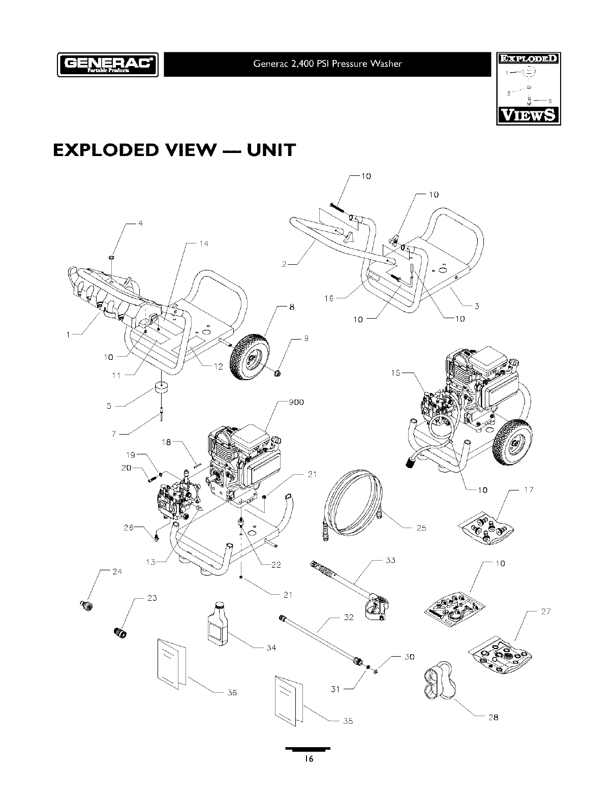
EXPLODED VIEW --- UNIT
_1o
lO
11
5
15_ \\
/
7 _
18_ \
19_ \\
20_ \
_35
17
\\\ 28
/
16
2 ¸ _rs
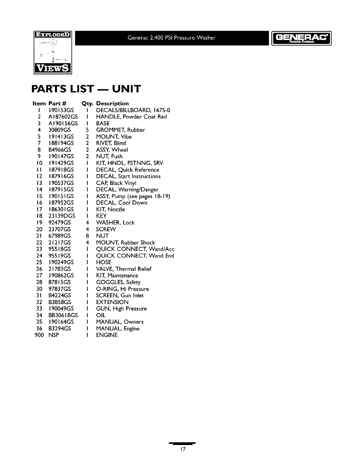
PARTS LIST--- UNIT
Item PaX #
I 190153GS
2 AI87602GS
3 AI90156GS
4 30809GS
5 191413GS
7 188194GS
8 B4966GS
9 190147GS
10 191429GS
II 187918GS
12 187916GS
13 190537GS
14 187915GS
15 190151GS
16 187952GS
17 186301GS
18 23139DGS
19 92479GS
20 23707GS
21 67989GS
22 21217GS
23 95518GS
24 95519GS
25 190249GS
26 21783GS
27 190862GS
28 87815GS
30 97837GS
31 B4224GS
32 B3858GS
33 190049GS
34 BB3061BGS
35 190164GS
36 B3294GS
900 NSP
Q_
I
I
I
5
2
2
2
2
4
4
8
4
Description
DECALS/BILLBOARD, 1675-0
HANDLE, Powder Coat Red
BASE
GROMMET, Rubber
MOUNT, Vibe
RIVET,Blind
ASSY,Wheel
NUT, Push
KIT, HNDL, FSTNNG, SRV
DECAL, Quick Reference
DECAL, Start Instructions
CAP, Black Vinyl
DECAL, Warning/Danger
ASSY,Pump (see pages 18-19)
DECAL, Coot Down
KIT, Nozzle
KEY
WASHER, Lock
SCREW
NUT
MOUNT, Rubber Shock
QUICK CONNECT, Wand/Acc
QUICK CONNECT, Wand End
HOSE
VALVE,Thermal Relief
KIT, Maintenance
GOGGLES, Safety
O-RING, Hi Pressure
SCREEN,Gun Inlet
EXTENSION
GUN, High Pressure
OIL
MANUAL, Owners
MANUAL, Engine
ENGINE
/
17
2 ¸
_rs
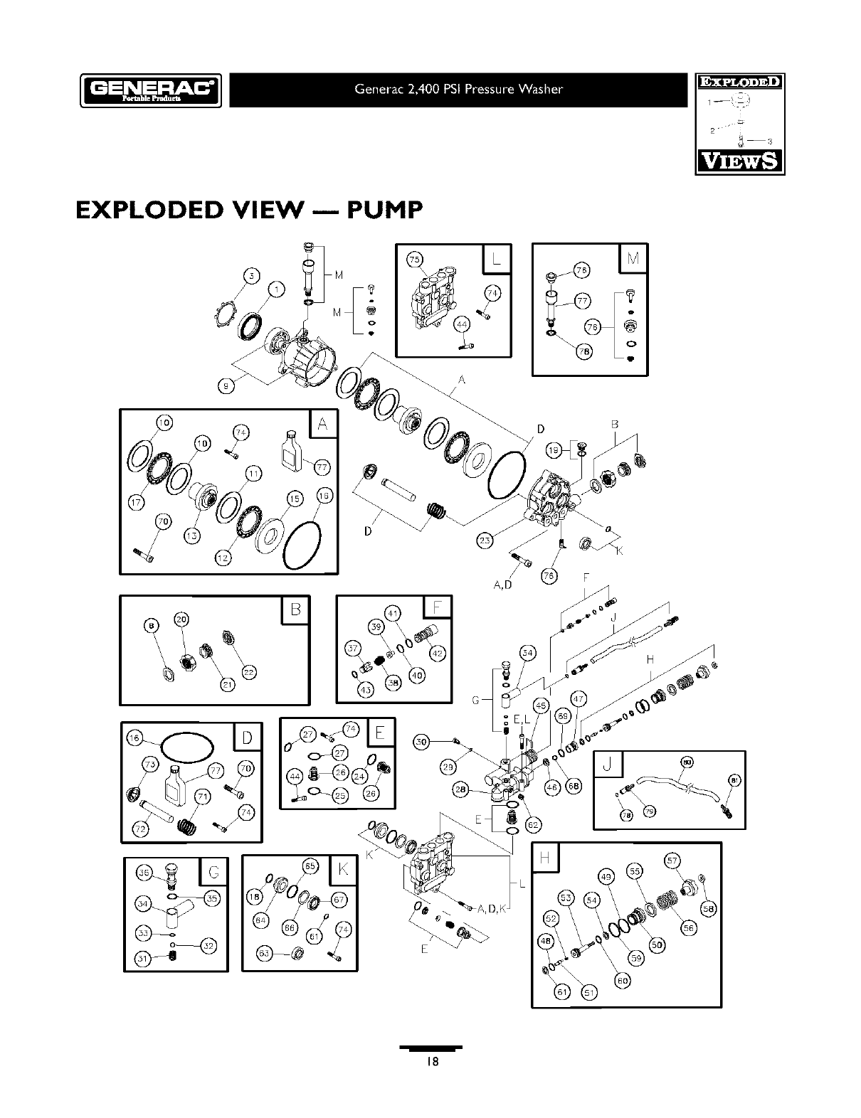
EXPLODED VIEW 1PUMP
o L
C)_@ %
A
E
D B
A,D (_ F
H
,iii
18
2 ¸ _r3
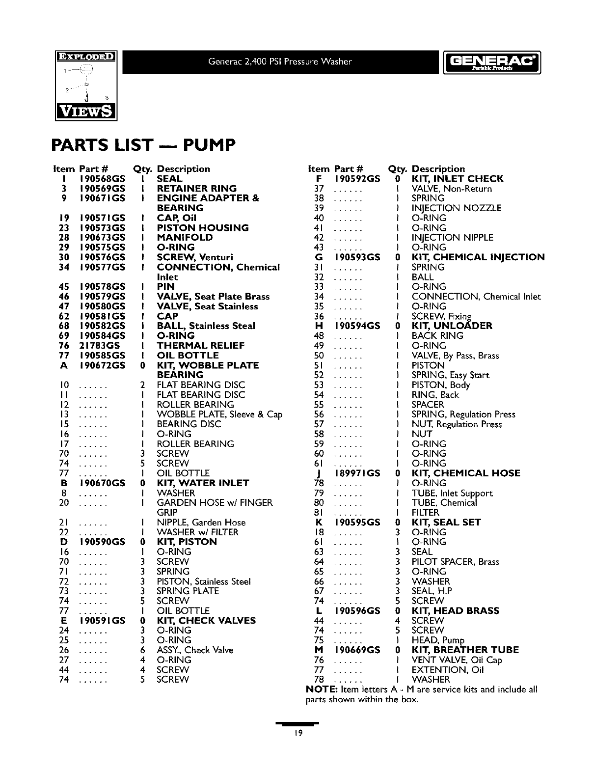
PARTS LIST-- PUMP
Item Part # Qty.
I 190568GS I
3 190569GS I
9 190671GS I
19 190571GS
23 190573GS
28 190673GS
29 190575GS
30 190576GS
34 190577GS
45 190578GS
46 190579GS
47 190580GS
62 190581GS
68 190582GS
69 190584GS
76 21783GS
77 190585GS
A190672GS
l0 ....
II ....
12 ....
13 ....
15 ....
16 ....
17 ....
70 ....
74 ......
77 ......
B 190670GS
8 ......
20 ......
21 ......
22 ......
D 190590GS
16 ......
70 ......
71 ....
72 ....
73 ....
74 ....
77 ......
E 190591GS
24 ......
25 ......
26 ....
27 ....
44 ....
74 ....
o
2
0
I
I
I
I
0
I
3
3
3
3
5
I
0
3
3
6
4
4
5
Description
SEAL
RETAINER RING
ENGINE ADAPTER &
BEARING
CAP, OU
PISTON HOUSING
MANIFOLD
O-RING
SCREW, Venturi
CONNECTION, Chemical
Inlet
PIN
VALVE, Seat Plate Brass
VALVE, Seat Stainless
CAP
BALL, Stainless Steal
O-RING
THERMAL RELIEF
OIL BOTTLE
KIT, WOBBLE PLATE
BEARING
FLAT BEARING DISC
FLAT BEARING DISC
ROLLERBEARING
WOBBLE PLATE,Sleeve& Cap
BEARING DISC
O-RING
ROLLERBEARING
SCREW
SCREW
OIL BOTTLE
KIT, WATER INLET
WASHER
GARDEN HOSE w/FINGER
GRIP
NIPPLE,Garden Hose
WASHER w/FILTER
KIT, PISTON
O-RING
SCREW
SPRING
PISTON, StainlessSteel
SPRING PLATE
SCREW
OIL BOTTLE
KIT, CHECK VALVES
O-RING
O-RING
ASSY.,Check Valve
O-RING
SCREW
SCREW
Item Part #
F 190592GS
37 ....
38 ....
39 ....
40 ....
41 ....
42 ....
43 ....
G 190593GS
31 ....
32 ....
33 ....
34 ....
35 ....
36 ....
H 190594GS
48 ....
49 ....
50 ....
51 ....
52 ....
53 ....
54 ....
55 ....
56 ....
57 ....
58 ....
59 ....
60 ....
61
J189971GS
78 ......
79 ......
80 ......
81 ......
K 190595GS
18 ....
61 ....
63 ....
64 ....
65 ....
66 ....
67 ....
74 ....
L 190596GS
44 ......
74 ......
75 ......
M 190669GS
76 ......
77 ......
78 ......
Qty.
0
o
o
0
I
I
I
I
0
3
I
3
3
3
3
3
5
0
4
5
I
0
I
I
I
Description
KIT, INLET CHECK
VALVE,Non-Return
SPRING
INJECTION NOZZLE
O-RING
O-RING
INJECTION NIPPLE
O-RING
KIT, CHEMICAL INJECTION
SPRING
BALL
O-RING
CONNECTION, Chemical Inlet
O-RING
SCREW,Fixing
KIT, UNLOADER
BACK RING
O-RING
VALVE,By Pass,Brass
PISTON
SPRING, EasyStart
PISTON, Body
RING, Back
SPACER
SPRING, Regulation Press
NUT, Regulation Press
NUT
O-RING
O-RING
O-RING
KIT, CHEMICAL HOSE
O-RING
TUBE, Inlet Support
TUBE, Chemical
FILTER
KIT, SEAL SET
O-RING
O-RING
SEAL
PILOT SPACER,Brass
O-RING
WASHER
SEAL, H.P
SCREW
KIT, HEAD BRASS
SCREW
SCREW
HEAD, Pump
KIT, BREATHER TUBE
VENT VALVE,Oil Cap
EXTENTION, Oil
WASHER
NOTE: Item letters A - M are service kits and include all
parts shown within the box.
/19
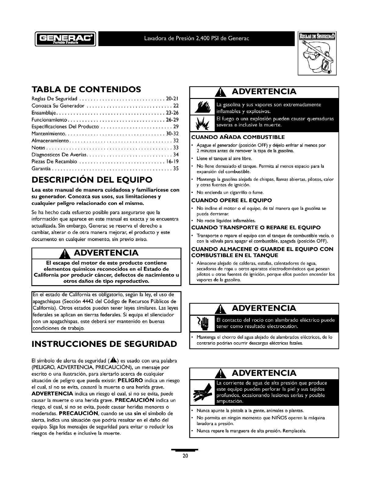
TABLA DE CONTENIDOS
ReglasDe Seguridad .............................. 20-21
Conozca Su Generador .............................. 22
Ensamblaje...................................... 23-26
Funcionamiento.................................. 26-29
Especificaciones Del Producto ......................... 29
Mantenimiento ................................... 30-32
AImacenamiento .................................... 32
Notas ............................................ 33
Diagnosticos De Averias .............................. 34
PiezasDe Recambio .............................. 16-19
Garantia .......................................... 35
DESCRIPCION DEL EQUIPO
Lea este manual de manera cuidadosa y familiaricese con
su generador. Conozca sus usos, suslimitaciones y
cualquier peligro relacionado con el mismo.
Se ha hecho cada esfuerzo posible para asegurarse que la
informacibnque aparece en este manual es exacta y se encuentra
actualizada. Sin embargo, Generac se reserva el derecho a
cambiar, alterar o de otra manera meiorar, el producto y este
documento en cualquier momento, sin previo aviso.
J ADVERTENCIA u
El escape del motor de este produeto eontiene
elementos quimieos reconoeidos en el Estado de
California pot producir e_ncer, defectos de naeimiento
otros da_os de tipo reproductivo.
Enel estado de California es obligatorio,seg0nla ley,el uso de I
_pagachispas(Seccibn 4442 del Cbdigo de Recursos P0blicos de
_alifornia). Otros estados pueden tener leyes similares. Lasleyes I
_ederalesse aplican en tierras federales. Si equipa el silenciador I
:on un apagachispas,este deberg ser mantenido en buenas
:ondicionesde trabaio.
INSTRUCCIONES DE SEGURIDAD
El simbolo de alerta de seguridad (_.) es usado con una palabra
(PELIGRO, ADVERTENCIA, PRECAUCI6N), un mensaje por
escrito ouna ilustracibn,para alertarlo acerca de cualquier
situacibn de peligro que pueda existir. PELIGRO indicaun riesgo
el cual, si no se evita, causar_la muerte ouna herida grave.
AOVEBTENClA indicaun riesgo el cual, si no se evita, puede
causar la muerte ouna herida grave. PRECAUCl6N indicaun
riesgo, el cual, si no se evita, puede causar heridas menores o
moderadas. PRECAUCl6N, cuando se usa sin el simbolo de
alerta, indicauna situacibn que podria resultar en el daho del
equipo. Sigalos mensaies de seguridad para evitar oreducir los
riesgos de heridas e inclusivela muerte.
ADVERTENCIA
CUANDO AI_IADA COMBUSTIBLE
Apagueel generador (posicibn OFF) y d_jelo enfriar al menos por
2 minutos antes de remover la tap_ de la gasolina.
Llene el tanque al aire libre.
No Ilene demasiado el t_nque_ Permita al menos espacio para la
expansibn del combustible.
Mantenga la gasolinaaleiada de chispas,llamas abiertas, pilotos, calor
y otras fuentes de ignicibn.
No encienda un cigarrillo o fume.
:UANDO OPERE EL EQUIPO
No inclineel motor o el equipo,de tal manera que la gasolina se
pueda derrama_
No rode llquidos inflamables.
:UANDO TRANSPORTE O BEPARE EL EQUIPO
Transporte o repare el equipo con el tanque de combustible vaclo, o
con la v_Ivula para apagar el combustible, apagada (posici6n OFF).
:UANDO ALMACENE O GUARDE EL EQUIPO CON
COMBUSTIBLE EN EL TANQUE
Almacene aleiadode calderas,estufas, calentadoresde agua,
secadoras de ropn uotros aparatos electrodom_sticosque posean
pilotos u otras fuentes de ignici6n, porque ellos pueden encender los
vapores de la gasolina.
ADVERTENCIA
Mantenga el chorro del agua alejado de alambrados el_ctricos, de Io
contrario podrlan ocurrir descargas el_ctricas fatales,
ADVERTENCIA
Nunca apunte la pistola a la gente, animales o plantas.
No permita en ningOn momento que NlixlOS operen la m_quina
lavadora a presi6n,
Nunca repare la manguera de aita presi6n. Remplacela.
i
20
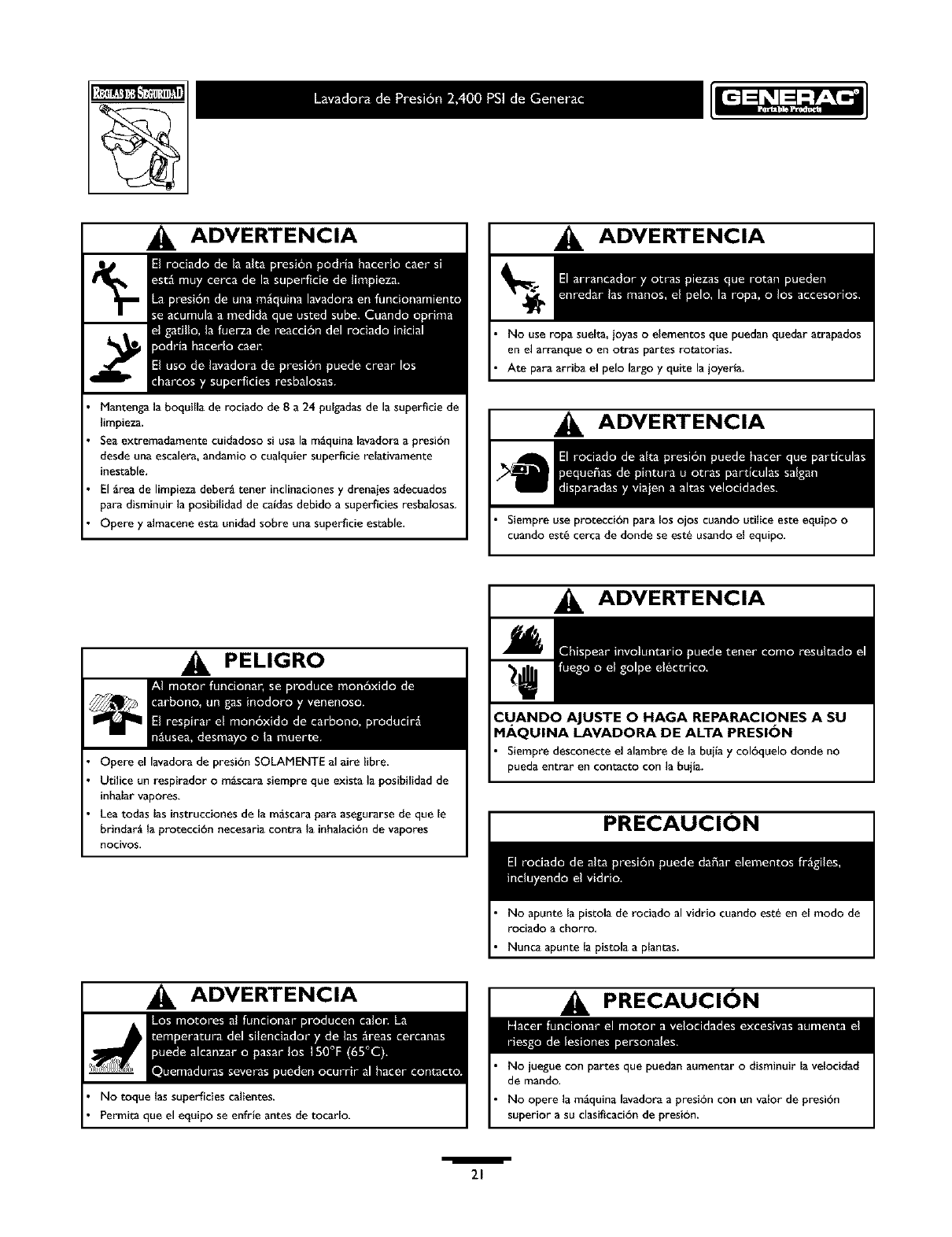
ADVERTENCIA
Manteng_ la boquilla de rociado de 8 a 24 pulgadasde la superficie de
limpieza.
Sea extremadamente cuidadoso si usa la m_quina lavadora a presibn
desdeuna escalera,andamio o cualquier superficie relativamente
inestable,
Elgrea de limpiezadeber_ tenet inclinaciones y drenajesadecuados
para disminuir la posibilidadde caidas debido a superficies resbalosas,
Opere y almacene esta unidad sobre una superficie estable,
ADVERTENCIA
No use ropa suelta, ioyas o elementos que puedan quedar atrapados
en el arranque o en otras partes rotatorias.
Ate para arriba el pelo largo y quite la joyeria.
ADVERTENCIA
Siempre use protecci6n para los ojos cuando utilice este ecluipo o
cuando est_ cerca de donde se est_ usando el equipo.
PELIGRO
Opere el lavadora de presi6n SOLAMENTE al aire libre.
Utilice un respirador o m_scara siempre que exista la posibilidad de
inhalar vapores_
Lea todas las instrucciones de la m_scara para asegurarse de que le
brindar_ la protecci6n necesaria contra la inhalaci6n de vapores
nocivos,
ADVERTENCIA
Siempre desconecte el alambre de la buila y col6quelo donde no
pueda entrar en contacto con la bujia.
PRECAUCION
No apunte la pistola de rociado al vidrio cuando est_ en el modo de
rociado a chorro,
Nunca apunte la pistola a plantas.
ADVERTENCIA
No toque las superficies calientes.
Permita que el equipo se enfrle antes de tocarlo.
PRECAUCION
No juegue con partes que puedan aumentar o disminuir la velocidad
de mando.
No opere la m_quina lavadora apresi6n con un valor de presi6n
superior a su clasificaci6n de presi6n.
i
21
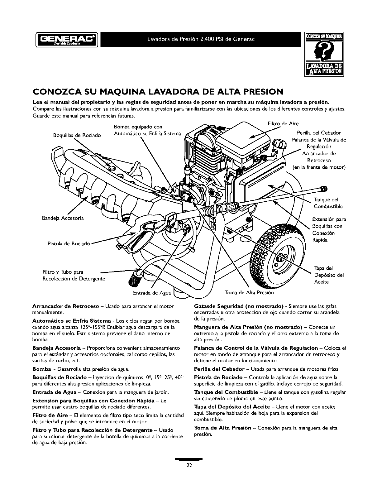
CONOZCA SU MAQUINA LAVADORA DE ALTA PRESION
Lea el manual del propietario y las reglas de seguridad antes de poner en marcha su m_quina lavadora a presi6n.
Compare las ilustracionescon su m_quina lavadora a presi6n para familiarizarse con las ubicaciones de los diferentes controles y ajustes.
Guarde este manual para referencias futuras.
Bomba equipado con
Autom_tico se EnfrfaSistema
Boquillas de Rociado
Filtro de Aire
Perilla del Cebador
Palancade la V_lvula de
Regulaci6n
de
P,etroceso
(en la frente de motor)
BandejaAccesoria
Pistola de Rodado
Tanque del
Combustible
Extensi6npara
Boquillas con
Conexi6n
R_pida
Filtro y Tubo para
Recolecci6n de Detergente
Entradade Agua
Arrancador de getroeeso - Usado para arrancar el motor
manualmente.
Automgtico se Enfria Sistema - Los ciclos regan por bomba
cuando aguaalcanza 125°- 155_°EEntibiar agua descargar_de la
bomba en el suelo. Este sistema previene el daho interno de
bomba.
Bandeja Aecesoria -Proporciona convenient almacenamiento
para el est_ndar y accesorios opcionales, tal como cepillos, las
varitas de turbo, ect.
Bomba - Desarrolla alta presi6n de agua.
Boquillas de Roeiado - lnyecci6n de quimicos, 0e, J5°, 25°, 40_:
para diferentes alta presi6n aplicaciones de limpieza.
Entrada de Agua - Conexi6n para la manguera de jardin.
Extensi6n para Boquillas con Conexi6n Rgpida - Le
permite usar cuatro boquillas de rociado diferentes.
Filtro de Aire - El elemento de filtro tipo seco limita la cantidad
de suciedad y polvo que se introduce en el motor.
Filtro y Tubo para Reeoleeci6n de Detergente - Usado
para succionar detergente de la botella de qufmicos a la corriente
de agua de baja presibn.
Toma de AIta Presi6n
Tapadel
Dep6sito del
Aceite
Gatasde Seguridad (no mostrado) - Siempre use las gafas
encerradas u otra protecci6n de ojo cuando correr su arandela
de la presibn.
Manguera de Alta Presibn (no mostrado) -Conecte un
extremo a la pistola de rociado y el otro extremo a la toma de
alta presi6n.
Patanca de Control de la Vglvula de Regulaci6n - Coloca el
motor en modo de arranque para el arrancador de retroceso y
detiene el motor en funcionamiento.
Perilla del Cebador - Usada paraarranque de motores frtos.
Pistola de gociado - Controla la aplicaci6n de aguasobre la
superficie de limpieza con el gatillo, incluye cerrojo de seguridad.
Tanque del Combustible - Llene el tanque con gasolina regular
sin contenido de plomo en este punto.
Tapa del Dep6sito del Aceite - Llene el motor con aceite
aquLSiempre habitaci6n de hoja para la expansi6n del
combustible.
Toma de Alta Presi6n - Conexi6n para la manguerade alta
presi6n.
i
22
IMPORTANTE: Lea totalmente el manual del propietario antes
que intente ensamblar u operar su lavador a alta presi6n.
REMUEVA EL LAVADOR A
ALTA PRESION DEL
EMPAQUE
Remuevala bolsa con las piezas,incluidascon el lavador de
alta presi6n.
Corte dos esquinas en los extremos del cartbn desde la parte
superior hasta la parte inferior, de tal manera que el p_nel
,uedaser doblado en forma plana, luego quite todo el
material de embala[e.
Ruede el lavador a alta presi6n fuera de la caja.
Contenido de la Caja
Los articulos que se encuentran en la caja son:
Unidad principal
Manguera de AIta Presi6n
Manubrio
BandeiaAccesoria Pl_stica
Botella de Aceite para Motor
Gafasde Seguridad
Pistola Rociadora
Extensi6n de la Lanzacon las Piezasde Conexi6n R_pida
Bolsade accesorios (incluye Io siguiente):
Juego de Mantenimiento
Manual del Propietario
Manual del Motor
Tarieta de Garantta del Motor
Tarieta de Garantta de Control de Emisiones
Tarieta de Registro del Propietario
Bolsa con 5 Lanzasde Conexiones RdpidasMulticolores
Piezaspara la manubrio (incluye Io siguiente):
Perno del Soporte
Perno "L"
PerillaPl_stica (2)
Gancho "J"
Clip Detergente de la Manga
Auto Utiliza Enrosca (5)
Si una de las partes que se mencionan arriba se encuentran
dafladasohacen falta, Ilame a la Ifneadirecta del lavador a alta
presibn,al 1-800-270-1408.
PREPARANDO EL
LAVADOR A ALTA
PRESION PARA SU USO
Si usted tiene un problemaal ensamblar la unidad o si hacen falta
algunaspiezaso se encuentran dafiadas, Ilame a la linea directa del
lavador a alta presi6n, al 1-800-270-1408.
A prepara su arandela de la presi6n para la operaci6n,
usted necesitarg arealiza estas tareas:
Uene y mande en tarjeta de matricula.
Conecte manubrio y bandeja accesoria a unidad principal.
Afiada aceite al motor.
Afiada gasolinaal tanque de combustible.
Conecte manguera a alta presi6n a pistola rociadora y a bomba.
Conecte el suministro de agua a bomba.
Conecte boquilla la extensi6n al pistola rociadora.
Selecto/conecta r_pido conecta boquilla a la extensi6n de la
boquilla.
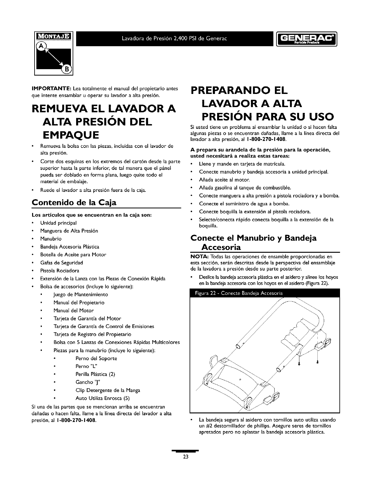
Conecte el Manubrio y Bandeja
Accesoria
NOTA: Todas las operaciones de ensamble proporcionadas en
esta secci6n, sergn descritas desde la perspectiva del ensamblaje
de la lavadora a presi6n desde su parte posterior.
Deslicela bandeiaaccesoriapl_tica en el asideroy alineelos hoyos
en labandejaaccesoriacon los hoyosen el asidero(Figura22).
La bandeja segura al asidero con tornillos auto utiliza usando
un #2 destornillador de phillips. Asegure seres de tornillos
apretados pero no aplastar la bandeja accesoria pl_stica.
/
23
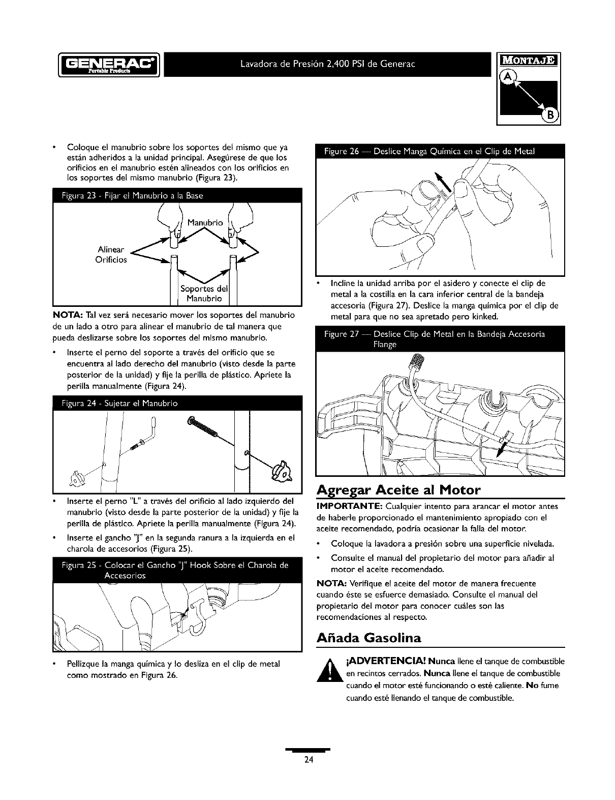
Coloqueelmanubriosobrelossoportesdelmismoqueya
est_nadheridosala unidad principal Aseg_rese de que los
orificios en el manubrio est_n alineados con los orificios en
los soportes del mismo manubrio (Figura 23).
Soportes del
Manubrio
NOTA: Talvez ser_ necesario mover los soportes del manubrio
de un lado a otro para alinear el manubrio de tal manera que
pueda deslizarse sobre los soportes del mismo manubrio.
Inserte el perno del soporte a tray,s del orificio que se
encuentra al lado derecho del manubrio (visto desde la parte
posterior de la unidad) y fije la perilla de pl_stico. Apriete la
perilla manualmente (Figura 24).
Inserte el perno "L" a tray,s del orificio al lado izquierdo del
manubrio (visto desde la parte posterior de la unidad) y fije la
perilla de pl_stico. Apriete la perilla manualmente (Figura 24).
Inserte el gancho "J" en la segunda ranura a la izquierda en el
charola de accesorios (Figura 25).
Pellizque la mangaquimica y Io desliza en el dip de metal
como mostrado en Figura 26.
\
Inclinela unidad arriba pot el asidero y conecte el dip de
metal a la costilla en la cara inferior central de la bandeia
accesoria (Figura 27). Deslice la manga quimica por el clip de
metal para que no sea apretado pero kinked.
Agregar Aceite al Motor
IMPORTANTE: Cualquier intento para arancar el motor antes
de haberle proporcionado el mantenimiento apropiado con el
aceite recomendado, podria ocasionar la faila del motor.
Coloque la lavadoraa presi6n sobre una superficie nivelada.
Consuite el manual del propietario del motor para a_adir al
motor el aceite recomendado.
NOTA: Verifique el aceite del motor de manera frecuente
cuando _ste se esfuerce demasiado. Consulte el manual del
propietario del motor para conocer cuglesson las
recomendaciones al respecto.
A ada Gasolina
_L ADVERTENCIA! Nunca Ilene el tanque de combustibleen recintos cerrados. Nunca Iiene el tanque de combustible
cuando el motor est_ funcionando o est_ caJiente.No fume
cuandoest_ Ilenando el tanque de combustible.
i
24
_IL ADVERTENClA! Nunca Ilene por completo el
tanque de combustible. Deje espacio para la expansi6n del
combustible.Limpie cualquierderrame de combustibledel
motor y del equipo antes de darle arranque a la unidad.
Use combustible limpio y almac_nelo en recipientes cubiertos,
limpios y aprobados. Utilice embudos limpios. Nunca utilice
gasolina "vieja" deiadade la estacibn anterior o gasolina
almacenada por periodos de tiempo prolongados.
Limpie el _,reaalrededor de la tapa de Ilenado del
combustible, retire la tapa.
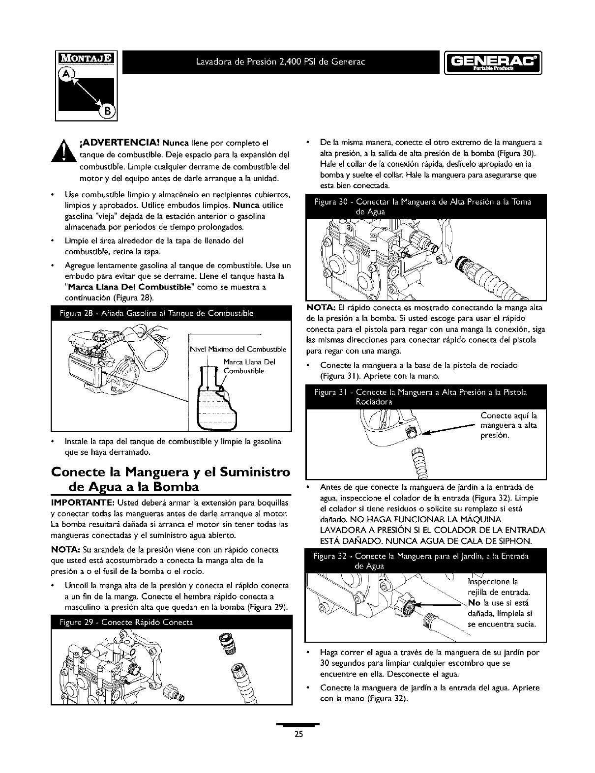
Agregue lentamente gasolina al tanque de combustible. Use un
embudo para evitar que se derrame. Llene el tanque hasta la
"Harca Liana Del Combustible" como se muestra a
continuaci6n (Figura 28).
Nivel M_ximo del Combustible
Marca Liana Del
_bustible
Instalela tapa del tanque de combustible y limpie la gasolina
que se hayaderramado.
Conecte la Manguera y el Suministro
de Agua a la Bomba
IMPOI_rANTE: Usted deber_ armar la extensi6n para boquillas
y conectar todas las mangueras antes de darle arranque al motor.
La bomba resultar_ daffada si arranca el motor sin tener todas las
mangueras conectadas y el suministro agua abierto.
NOTA: Su arandela de la presi6n viene con un r_pido conecta
que usted est_ acostumbrado a conecta la manga alta de la
presi6n a o el fusil de la bomba o el roclo.
Uncoil la manga alta de la presi6n y conecta el r_pido conecta
a un fin de la manga. Conecte el hembra r_pido conecta a
masculino la presi6n alta que quedan en la bomba (Figura 29).
De la misma manera, conecte el otto extremo de la manguera a
alta presi6n, a la salida de alta presi6n de la bomba (Figura 30).
Hale el collar de la conexi6n r_oida, desltcelo apropiado en la
bombay suelte el collal: Hale la manguera para asegurarse que
esta bien conectada.
mill |
NOTA: El r_pido conecta es mostrado conectando la manga alta
de la presi6n a la bomba. Si usted escoge para usar el r_pido
conecta para el pistola para regar con una manga la conexi6n, siga
las mismas direcciones para conectar r_pido conecta del pistola
para regar con una manga.
Conecte la manguera a la base de la pistola de rociado
(Figura 3 I). Apriete con la mano.
Conecte aqulla
manguera a alta
presi6n.
Antes de que conecte la manguera de iardtn a la entrada de
agua, inspeccione el colador de la entrada (Figura 32). Limpie
el colador si tiene residuos o solicite su remplazo si est_
daffado. NO HAGA FUNCIONAR LA M,&,QUINA
LAVADORA A PRESI6N SI EL COLADOR DE LA ENTRADA
EST/k DANADO. NUNCA AGUA DE CALA DE SIPHON.
Haga correr el agua a tray,s de la manguera de su iardln por
30 segundos para limpiar cualquier escombro que se
encuentre en ella. Desconecte el agua.
Conecte la manguera de jardln a la entrada del agua.Apriete
con la mano (Figura 32).
i
25
iPRECAUCI(_N! DEBE haber por Iomenos diezpiesde
manguera de iardinfibreentre laentradade agua de lalavadoraa
presi6ny eualquierdispositivode controlde fluiode agua,seaelcaso
de un eonector 'Y'o de eualquierotro tipode v_Ivula.Elda_o a la
lavadora a presi6n, resultado de la desatenci6n a esta precauci6n, no
ser_ cubierto por la garantlai
ABRA el suministro del agua (abra la v_lvula de suministro
completamente).
_L PRECAUCI(_N! Antes de darle arranque a la m_quina
lavadora a presi6n, asegOresede usar proteccibn adecuada
para los ojos.
Lista de Revision Previa al Arranque
del Motor
Revise la unidad para asegurarse que ha Ilevado a cabo los
siguientes procedimientos:
Cerci6rese el manecilla es seguro.
Reviseque hayasido depositado aceite y est_ al nivel correcto
en la caja del cigtie_al del motor.
Deposite la gasolina adecuadaen el tanque del combustible.
Reviseque todas lasconexiones de lasmangueras(alta presibn y
suministro de agua)est_n apretadas correctamente y que no
existan dobleces,cortes o da_o de la manguerade alta presi6n.
Proporcione el suministro de aguaadecuado.
Aseg_rese de leer lassecciones "Reglasde Seguridad" y
"Cbmo Darle Arranque a su M_quina Lavadora a Presi6n"
antes de usar la m_quina lavadora a presi6n.
COMO USAR SU
MAQUINA LAVADORA
APRESION
Si tiene problemas operando su mgquina lavadora a presi6n, por
favor Ilame a la linea de ayudapara m_quinas lavadoras a presi6n
al 1-800-270-1408.
C6mo Darle Arranque a su MAquina
Lavadora a Presibn
Para darle arranque a su m_quina lavadora a presi6n movida a
motor pot primera vez, siga estas instruccionespasoa paso. Esta
informacibnacerca del arranque inicialtambi_n se aplica cuando
vayaa darle arranque al motor despu_s de haber dejado de la
m_quina lavadora a presibn fuera de uso por al menos un dta.
Coloque la mgquinalavadoraa presibn en un _reacercanaa una
suministro de aguaexterior capazdeabasteceraguaa un volumen
mayor de 2.8galonespor minuto.
Revise que la manguera de alta presibn se encuentre
conectada flrmemente a la pistola de rociado y a la bomba.
Vea"Preparandoel Lavador a Alta Presi6n Parasu Uso".
Aseg_rese que la unidad est_ nivelada.
Conecte la manguera de jardtn a la entrada del agua.Aprietela
con la mano. Abra el suministro de agua.
iPRECAUCI(_N! No hagafuncionar la bomba si no tiene el
suministro conectado y abierto. Deber_ cumplir con esta
precauci6n, de otra forma la bomba resultar_ dahada.
Apriete firmemente el gatillo de la pistola para purgar de aire
eimpurezasel sistema de bombeo.
Conecte la extensi6n de la lanza a la pistola rociadora.
Apri_tela con las manos (Figura 33).
Seleccione la boquilla de conexibn r_pida que usted deseee
ins_rtelaen el extremo de la extensibn de la lanza (Vea
"Como Usar las Boquillas").
Coloque el pasador de seguridad al gatillo de la pistola
rociadora (Figura 34).
El Pasadorde la
Seguridad
Para encender un motor frfo, mueva la palancade la bobina a
la posici6n de "Cerrado" ("Closed") (Figura35).
Palancade la Bobina /,
i
26
NOTA: Paraencender de nuevo un motor caliente, deie la palanca
de la bobina en la posicibn de "Abierto" ("Open").
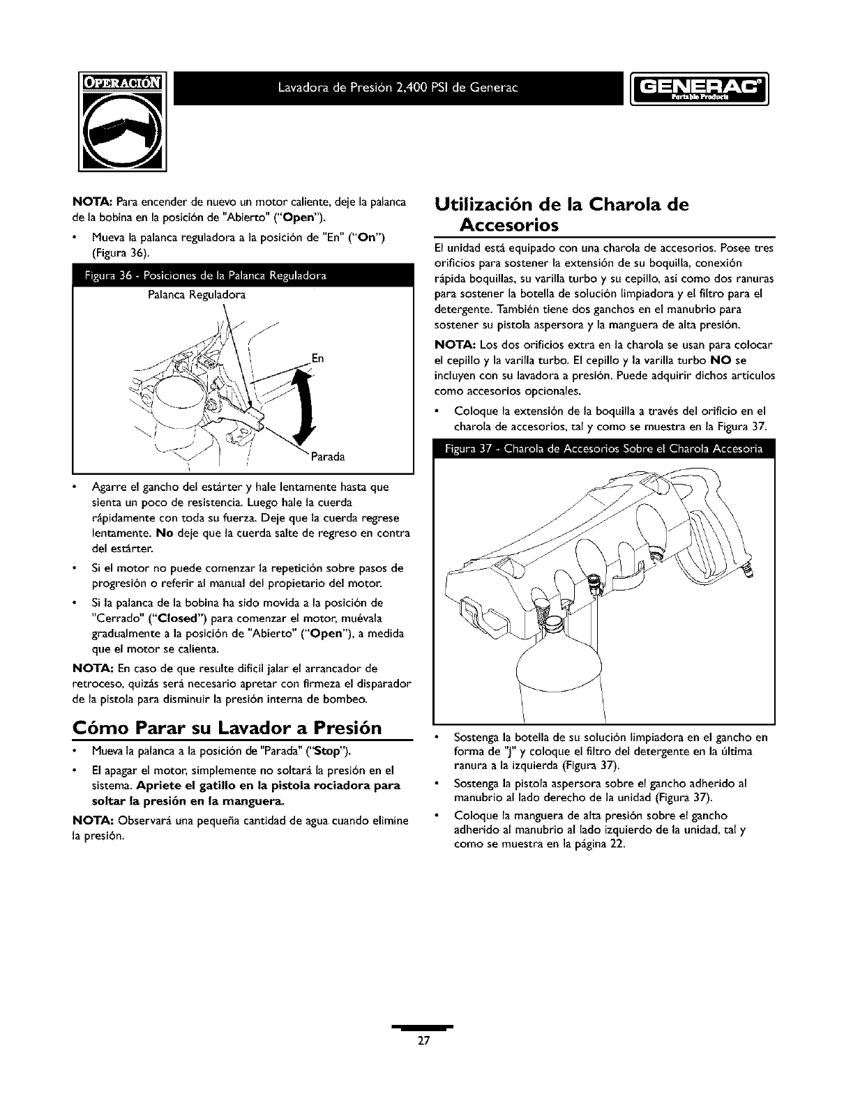
Mueva la palancareguladora a la posicibn de "En" ("On")
(Figura 36).
PalancaReguladora
En
! J •
\J_J arada
_rre elganchodeles_rtery halelen_mentehastaque
sien_un poco de resistencia.Luegohalelacuerde
r_pidamentecontodasufuerza.Deieque lacuerdaregrese
len_mente.No deieque lacuerdasaltede regresoen contra
del est_rten
Si el motor no puede comenzar la repeticibn sobre pasos de
progresibn oreferir al manual del propietario del motor.
Si la palancade la bobina ha sido movida a la posicibn de
"Cerrado" ("Closed") para comenzar el motor, mu_vala
gradualmente a la posicibn de "Abierto" ("Open"), a medida
que el motor se calienta.
NOTA: En casode que resulte dificil jalar el arrancador de
retroceso, quiz_s ser_ necesario apretar con firmeza el disparador
de la pistola para disminuir la presibn interna de bombeo.
mmea._
C6mo Parar su Lavador a Presi6n
Muevala palancaa la posici6nde"Parada" ('_top").
El apagarel motor, simplemente no soltar_ la presibn en el
sistema. Apriete el gatillo en la pistola rociaclora para
soltar la presi6n en la manguera.
NOTA: Observar_ una peque6a cantidad de aguacuando elimine
la presi6n.
Utilizaci6n de la Charola de
Accesorios
El unidad est_ equipado con una charola de accesorios. Poseetres
oriflcios para sostener la extensibn de su boquilla, conexibn
r_pida boquillas, su varilla turbo y su cepillo, asi como dos ranuras
para sostener la botella de solucibn limpiadora y el filtro para el
detergente. Tambi6n tiene dos ganchos en el manubrio para
sostener su pistola aspersora y la manguera de alta presi6n.
NOTA: Los dos orificios extra en la charola se usan para colocar
el cepillo y la varilla turbo. El cepillo y la varilla turbo NO se
incluyencon su lavadora a presi6n. Puedeadquirir dichos articulos
como accesorios opcionales.
Coloque la extensi6n de la boquilla a trav6s del orificio en el
charola de accesorios, tal y como se muestra en la Figura37.
Sostengala botella de su solucibn limpiadora en el gancho en
forma de "J" y coloque el filtro del detergente en la t%ltima
ranura a la izquierda(Figura 37).
Sostengala pistola aspersora sobre el gancho adherido al
manubrio al lado derecho de la unidad (Figura 37).
Coloque la manguera de alta presibn sobre el gancho
adherido al manubrio al lado izquierdode la unidad, tal y
como se muestra en la p_gina22.
i
27
C6mo Usar las Boquillas
_L PRECAUCI_N! Nunca intercambie boquillas sin
haber asegurado el cerroio de seguridad del gatillo.
La conexibn r_pida de la extensibn para boquillas le permite usar
cuatro boquillas diferentes. Las boquillas tienen diferentes
patrones de rociado como se ilustra a continuacibn (Figura 38).
Para cambiar las boquillas:
Enganche e_cerrojo de seguridad de la pistola de rociado.
Mueva hacia atr_s el collar de la conexibn r_pida y saque la
boquiHa insta_ada. Almacene _e boquiHa en el espacio
suministrado en e_ pane_ de control.
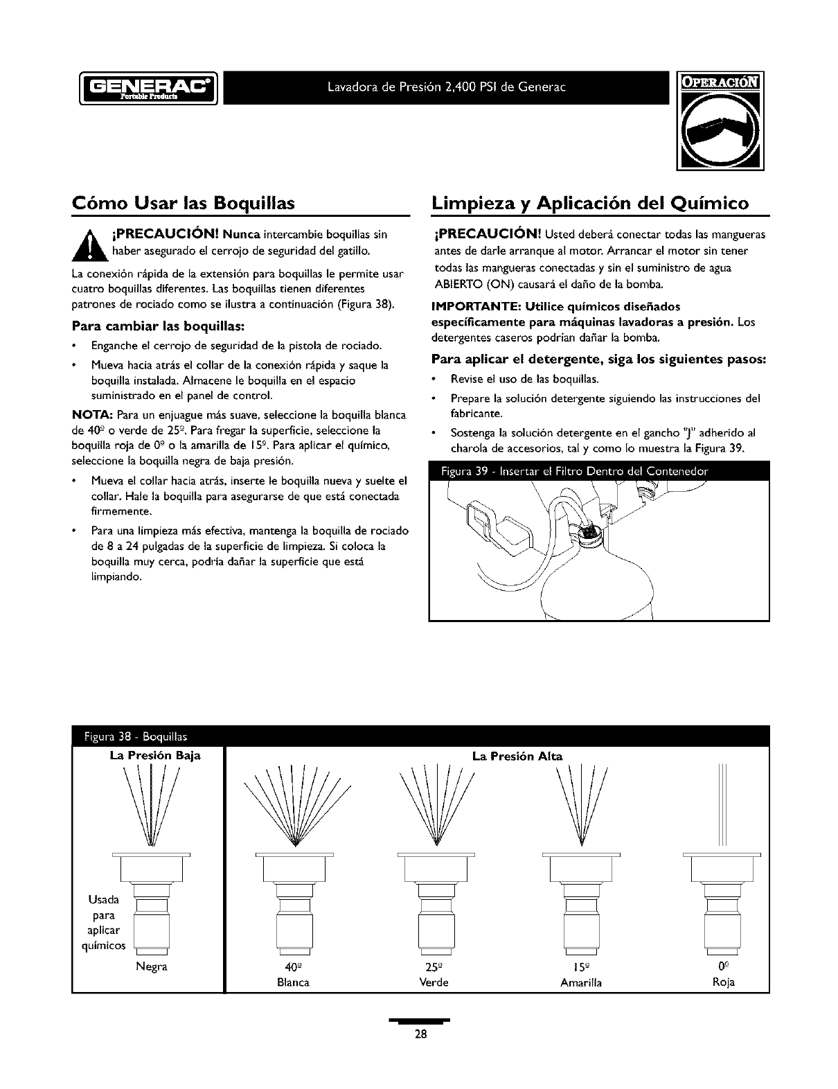
NOTA: Para un enjuague mgs suave, seleccione la boquilla blanca
de 40 ° o verde de 25 °. Para fregar la superficie, seleccione la
boquilla roja de 0 ° o la amarilla de 15°. Para aplicar el qufmico,
seleccione la boquilla negra de baja presibn.
Mueva e_collar hacia atr_s, inserte le boquilla nueva y suelte el
collar. Hale la boquil_a para asegurarse de que est_ conectada
firmemente.
Para una limpieza m_s efectiva, mantenga la boquiHa de rociado
de 8 a 24 pu_gadas de la superficie de fimpieza. Si coloca la
boquiHa muy cerca, podrla dahar la superficie que est_
ffmpiando.
Limpieza y Aplicaci6n del Quimico
iPRECAUCI_N! Usted deber_ conectar todas lasmangueras
antes de darle arranque al motor. Arrancar el motor sin tener
todas las manguerasconectadas y sin el suministro de agua
ABIERTO (ON) causar_ el da_o de la bomba.
IMPORTANTE: Utilice quimicos disefiados
especificamente para m_quinas lavadoras a presi6n. Los
detergentes caseros podrian da_ar la bomba.
Para aplicar el detergente, siga los siguientes pasos:
Revise el uso de las boquil_as.
Prepare _asolucibn detergente siguiendo las instruccionesdel
fabricante.
Sostengala solucibn detergente en el gancho ']" adherido al
charola de accesorios, tal y como Io muestra la Figura 39.
La Presi6n Baja
Negra
La Presi6n Alta
40_ 25_ 15_ 0o
Blanca Verde Amarilla Roia
i
28
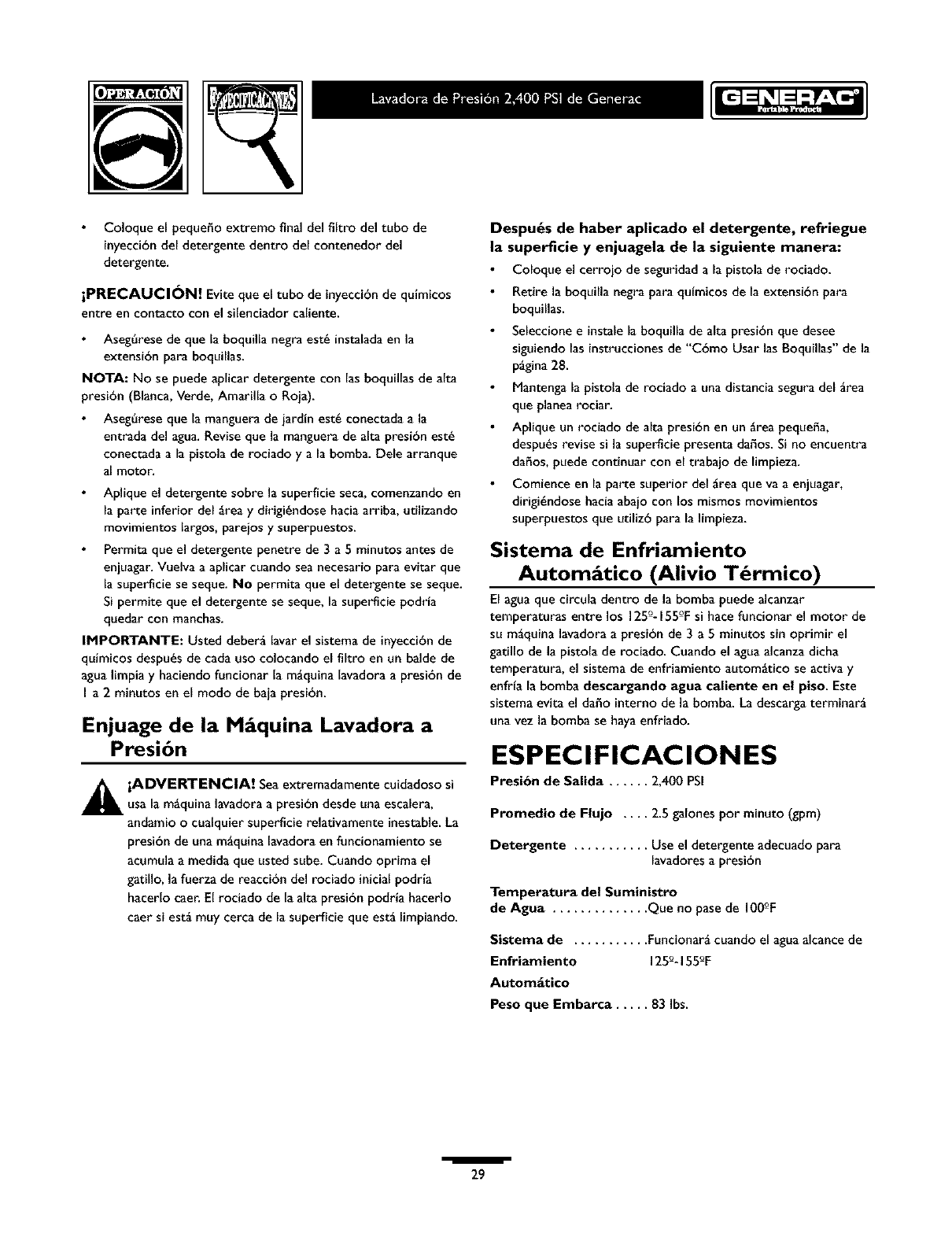
Coloque el pequeho extremo final del fiItro del tubo de
inyeccibndel detergente dentro del contenedor del
detergente.
iPRECAUCI_N! Eviteque el tubo de inyeccibnde quimicos
entre en contacto con el silenciador caliente.
Aseg6rese de que la boquilla negra est_ instalada en la
extensi6n para boquiHas.
NOTA: No se puede aplicar detergente con las boquillas de alta
presi6n (Blanca, Verde, Amarilla oRoja).
Aseg6rese que la manguera de jardfn est_ conectada a la
entrada del agua. Revise que la manguera de alta presi6n est_
conectada a la pistola de rociado y a la bomba. Dele arranque
al motor.
Aplique el detergente sobre la superficie seca, comenzando en
la parte inferior del grea y dirigi_ndose hacia arriba, utilizando
movimientos largos, pareios y superpuestos.
Permita que el detergente penetre de 3a 5 minutos antes de
enjuagar. Vuelva a apEcar cuando sea necesario para evitar que
la superficie se seque. No permita que el detergente se seque.
Si permite que el detergente se seque, la superficie podria
quedar con manchas.
IMPORTANTE: Usted deber_ lavar el sistema de inyecci6n de
quimicos despu_s de cada uso colocando el filtro en un balde de
agua limpia y haciendo funcionar la m_quina lavadora a presi6n de
I a 2 minutos en el modo de baia presi6n.
Enjuage de la M quina Lavadora a
Presi6n
_ADVERTENCIA! Seaextremadamente cuidadoso si
usa la mgquina lavadora a presibn desde una escalera,
andamio o cualquier superficie relativamente inestable.La
presibn de una m_quina lavadora en funcionamiento se
acumula a medida que usted sube. Cuando oprima el
gatillo, la fuerza de reaccibn del rociado inicialpodria
hacerlo caer.El rociado de la alta presibn podria hacerlo
caer si est_ muy cerca de la superficie que est_ limpiando.
Despu_s de haber aplicado el detergente, refriegue
la superficie y enjuagela de la siguiente manera:
Co_oque el cerrojo de seguridad a _apistola de rociado.
Retire la boquiHanegra para quimicos de _aextensi6n para
boquiHas.
Se_eccionee instate_aboquil_ade alta presibn que desee
siguiendo _asinstruccionesde "C6mo Usar las Boquil_as"de la
p_gina28.
Mantenga _apistola de rociado a una distancia segura de__rea
que planea rociar.
Aplique un rociado de alta presi6n en un _rea peque6a,
despu_s revise si la superficie presenta da_os.Si no encuentra
dahos, puede continuar con e_trabajo de Empieza.
Comience en _aparte superior de__rea que va a enjuagar,
dirigi_ndose hacia abajo con _osmismos movimientos
superpuestos que utiEz6 para _alimpieza.
Sistema de Enfriamiento
Automgtico (Alivio T rmico)
El aguaque circula dentro de la bomba puede alcanzar
temperaturas entre los 125°-_55°F si hace funcionar el motor de
su m_quina lavadora a presibn de 3 a 5 minutos sin oprimir el
gatillo de la pistola de rociado. Cuando el aguaalcanzadicha
temperatura, el sistema de enfriamiento autom_tico se activa y
enfrta la bomba descargando agua caliente en el piso. Este
sistema evita el da_o interno de la bomba. La descarga terminar_
una vez la bomba se hayaenfriado.
ESPECIFICACIONES
Presi6n de Salida ...... 2,400 PSI
Promedio de Flujo .... 2.5 galones por minuto (gpm)
Detergente ........... Use el detergente adecuado para
lavadores a presi6n
Temperatura del Suministro
de Agua .............. Que no pasede 100OF
Sistema de ........... Funcionar_ cuandoel aguaalcance de
Enfriamiento 125°- 155°F
Automgtico
Peso que Embarca ..... 83 Ibs.
/
29
RECOMENDACIONES
G EN ERALES
La garantta de la m_quina lavadoraa presi6n no cubre los
elementos que hart sido sujetos a abuso o negligencia por parte
del operador. Para hacer v_lida la cobertura total de la garantia, el
operador deber_ mantener la lavadora de presi6n tal y como se
indicaen el manual.
Algunos ajustes tendr_n que hacerse peri6dicamente para
mantener adecuadamente su mgquina lavadora a presi6n.
Todos los servicios y ajustes deber_n hacerse por Io menos
una vez en cada estaci6n.
Una vez al a_o, usted deber_ limpiar oremplazar la bujfa y el
filtro de aire. Una buiia nuevay un flltro de aire limpio
garantizan una mezcla de combustible-aire adecuaday le ayuda
a su motor a funcionar mejor y a tener una vida _til m_s
prolongada. Por favor, para mayores detalles, consulte el
manual del propietario del motor.
Antes de Cada Uso
Reviseel nivel de aceite del motor.
Revisesi existen da_os en el colador de la entrada de agua.
Revisesi existen da_os en el filtro en Ifnea.
Revisesi existen fugas en la manguera de alta presi6n.
Revisesi existen da_os en los flltros de qufmicos.
Revisesi existen fugas en el conjunto de la extensi6n para
boquillas y pistola.
Elimine el aire y los contaminantes de la bomba.
MANTENIMIENTO DE LA
MAQUINA LAVADORA A
PRESION
Revise y Limpie el Colador de
Entrada
Examineel colador de entrada de la manguera de iardin. Ltmpielo
si est_ tapado oremplacelo si est_ roto.
Revise la Manguera de Alta Presi6n
Las manguerasde alta presi6n pueden desarrollar fugas debido al
desgaste, dobleces oabuso. Revise la manguera antes de cada uso.
Revisesi existen cortes, fugas,abrasiones, levantamiento de la
cubierta, daho omovimiento de los acoplamientos. Si existe
cualquiera de estas condiciones, remplace la manguera
inmediatamente.
_IL PRECAUCI_N! Nunca repare la manguera de altapresi6n. Remplacelacon una mangueraque cumpla con la
capacidad minima de presi6n de su m_quina lavadora a
presi6n.
Chequee el Tubo de Sif6n del
Detergente
Examineel flltro en el tubo del detergente y Hmpielo si se
encuentra sucio. Eltubo deberla quedar apretado en la pieza.
Examine el tubo para ver si existe cualquier tipo de goteo oest_
roto. Reemplace el filtro oel tubo si alguno de ellos se encuentra
dahado.
Limpiando el Tubo
Si usted us6 el tubo, usted debe lavarlo con agualimpia antes de
parar el motor.
Coloque el filtro y la inyecci6nqufmica en un balde Ileno de
agualimpia.
Conecte la lanza negra de baia presi6n.
Lave de I a 2 minutos.
Apague el motor.
IMPORTANTE: Apagando el motor, simplemente no soltar_ la
presi6n en el sistema. Cuando el motor se ha apagado,
apriete el gatillo en la pistola rociadora para deshacerse
de la presi6n en la manguera_
Revise la Pistola y la Extensi6n para
Boquillas
Examinela conexi6n de la mangueraa la pistola y cerciorese de
que est6 en buen estado. Pruebe el gatillo oprimi6ndolo y
asegur_ndose de que se devuelve a su sitio cuando Io suelte.
Coloque el cerrojo de seguridad y pruebe el gatillo. Usted no
debe ser capaz de oprimir el gatillo. Remplace la pistola
inmediatamentesi falla cualquiera de estas pruebas.
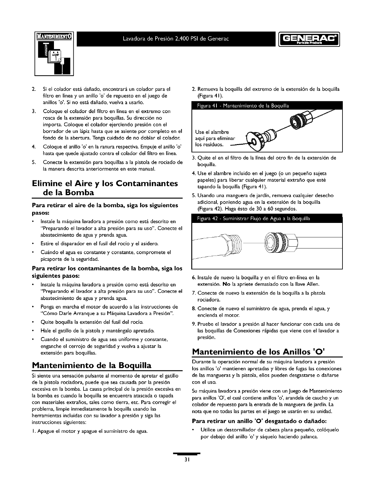
Revise el Filtro en Linea
Consulte la Figura 40 y suministre servicio al filtro en linea si se
tapa siguiendo estos pasos:
_-_ Filtro en Linea
Extensi6n de la Boqq
Anillo 'O'
I. Retire la pistola y la extensi6n para boquillas de la manguera
de alta presibn. Retire la extensibn para boquillas de la
pistola y retire el anillo 'o' y el colador de la extensibn para
boquillas. Lave el colador, pistola y extensibn para boquillas
con agua limpia para eliminar toda clase de residuos.
/
30
2.
3.
4.
5.
Si el colador est_ dahado, encontrar_ un colador para el
filtro en linea y un anillo 'o' de repuesto en el iuego de
anillos 'o'. Si no est_ daffado, vuelva a usarlo.
Coloque el colador del filtro en linea en el extremo con
rosca de la extensi6n para boquillas. Su direcci6n no
importa. Coloque el colador ejerciendo presi6n con el
borrador de un Igpiz hasta que se asiente por completo en el
rondo de la abertura. Tenga cuidado de no doblar el colador.
Coloque el anillo 'o' en la ranura respectiva. Empuie el anillo 'o'
hasta que quede aiustado contra el colador del flltro en llnea.
Conecte la extensi6n para boquillas a la pistola de rociado de
la manera descrita anteriormente en este manual.
Elimine el Aire y los Contaminantes
de la Bomba
Para retirar el aire de la bomba, siga los siguientes
pasos:
Instale la m_quina lavadora a presi6n como est_ descrito en
"Preparando el lavador a alta presi6n para su uso". Conecte el
abastecimiento de agua y prenda agua.
Estire el disparador en el fusil del rocio y el asidero.
Cu_ndo el agua es constante y constante, compromete el
picaporte de la seguridad.
Para retirar los contaminantes de la bomba, siga los
siguientes pasos:
Instale la m_quina lavadora a presi6n como est_ descrito en
"Preparando el lavador a alta presi6n para su uso". Conecte el
abastecimiento de agua y prenda agua.
Ponga en marcha el motor de acuerdo alas instrucciones de
"C6mo Darle Arranque a su M_quina Lavadora a Presi6n".
Quite boquilla la extensi6n del fusil del roclo.
Hale el gatillo de la pistola y mant_ngalo apretado.
Cuando el suministro de agua sea uniforme y constante,
enganche el cerrolo de seguridad y vuelva a alustar la
extensi6n para boquillas.
Mantenimiento de la Boquilla
Si siente una sensaci6n pulsante al momento de apretar el gatillo
de la pistola rociadora, puede que sea causada por la presi6n
excesiva en la bomba. La causa principal de la presi6n excesiva en
la bomba es cuando la boquilla se encuentra atascada o tapada
con materiales extraffos, tales como tierra, etc. Para corregir el
problema, limpie inmediatamente la boquilla usando las
herramientas induidas con su lavador a presi6n y siga las
instrucciones siguientes:
I. Apague el motor y apague el suministro de agua.
2. Remueva la boquilla del extremo de la extensi6n de la boquilla
(Figura 4 I).
los residuos.
3. Quite el en el flltro de la linea del otro fin de la extensi6n de
boquilla.
4. Use el alambre incluido en el iuego (o un pequeffo sujeta
papeles) para liberar cualquier material extraffo que est_
tapando la boquilla (Figura 41).
5. Usando una manguera de jardin, remueva cualquier desecho
adicional, poniendo agua en la extensi6n de la boquilla
(Figura 42). Haga _sto de 30 a 60 segundos.
6. lnstale de nuevo la boquilla yen el filtro en-linea en la
extensi6n. No la apriete demasiado con la flare Allen.
7. Conecte de nuevo la extensi6n de la boquilla a la pistola
rociadora.
8. Conecte de nuevo el suministro de agua, prenda el agua, y
encienda el motor.
9. Pruebe el lavador a presi6n al hacer funcionar con cada una de
las boquillas de Conexiones r_pidas que viene con el lavador a
presi6n.
Mantenimiento de los Anillos '0'
Durante la operaci6n normal de su m_quina lavadora a presi6n
los anillos 'o' mantienen apretadas y fibres de fugas las conexiones
de las mangueras y la pistola, ellos pueden desgastarse o daharse
con el uso.
Su m_quina lavadora a presi6n viene con un Juego de Mantenimiento
para anillos '0', el cual contiene anillos 'o', arandela de caucho y un
colador de repuesto para la entrada de la manguera de jardin. La
nota que no todas las partes en el juego se usar_n en su unidad.
Para retirar un anUlo '0' desgastado oda_ado:
Utilice un destornillador de cabeza plana pequeffo, col6quelo
por debajo del anillo 'o' y s_quelo haciendo palanca.
I
31
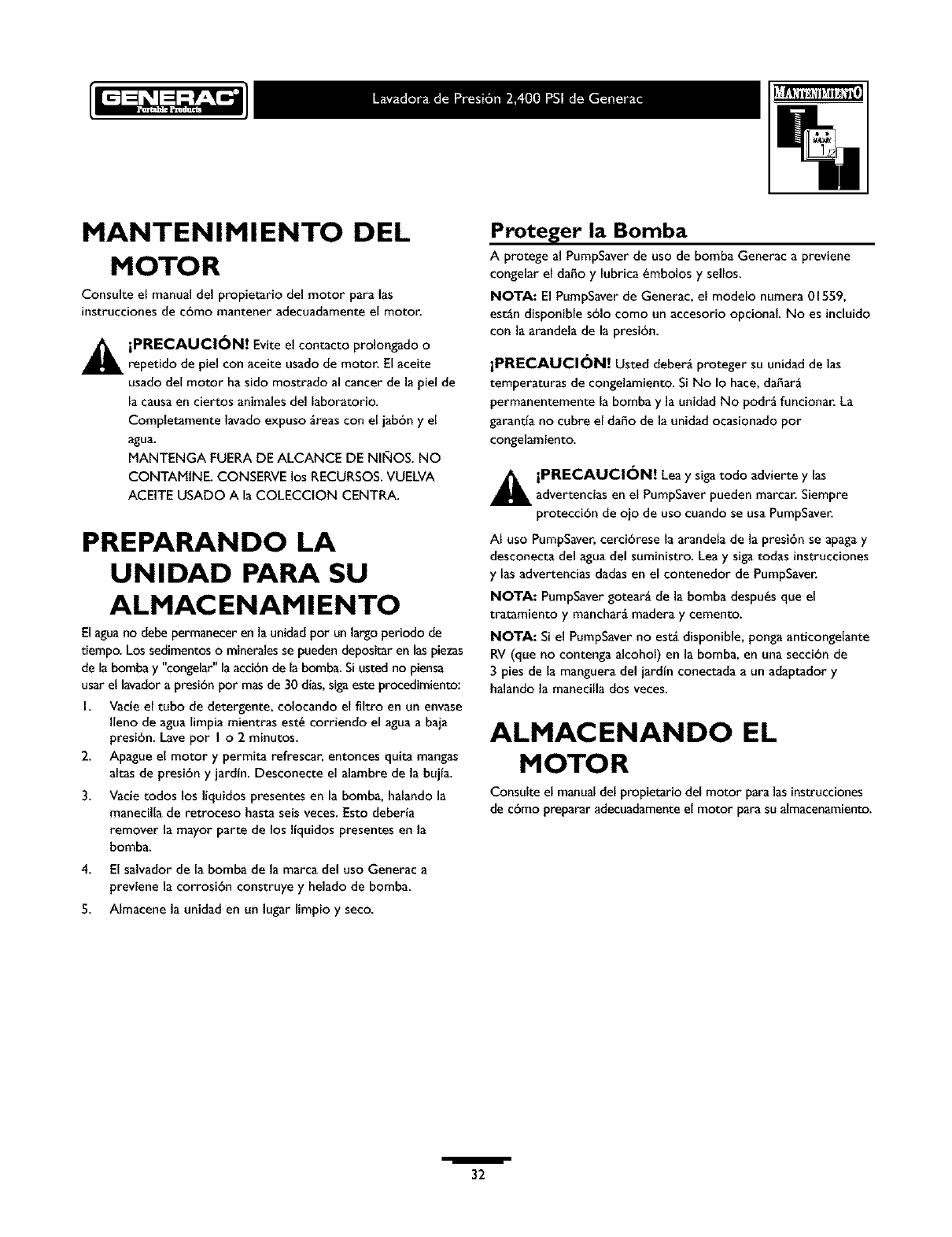
MANTENIMIENTO DEL
MOTOR
Consulte e[ manual del propietario del motor para las
instruccionesde cbmo mantener adecuadamente el motor.
_L iPRECAUCI_N! Evite el contacto prolongado o
repetido de piel con aceite usado de motor. El aceite
usado del motor ha sido mostrado al cancer de la piel de
la causaen ciertos animales del laboratorio.
Completamente lavado expuso greas con el jab6n y el
agua.
MANTENGA FUERA DE ALCANCE DE NI_IOS. NO
CONTAMtNE. CONSERVE los RECURSOS.VUELVA
ACEtTE USADO A la COLECCION CENTRA.
PREPARANDO LA
UNIDAD PARA SU
ALMACENAMIENTO
El aguano debe permanecer enla unidadpor unlargo periodode
tiempo. Lossedimentosomineralesse pueden depositar en laspiezas
de labombay "congetar"la acci6nde la bomba. Si usted no piensa
usar el lavadora presibn por masde 30 dias,sigaeste procedimiento:
I. Vacie el tubo de detergente, colocando el filtro en un envase
I[eno de agua [impiamientras est_ corriendo el agua a baja
presi6n. Lave pot I o2 minutos.
2. Apague el motor y permita refrescar, entonces quita mangas
altas de presibn y jardfn. Desconecte el alambre de la bujfa.
3. Vacie todos los liquidos presentes en la bomba, halando la
manecilla de retroceso hasta seisveces. Esto deberia
remover la mayor parte de los Ifquidos presentes en la
bomba.
4. El salvador de la bomba de la marca del uso Generac a
previene la corrosi6n construye y helado de bomba.
5. AImacene la unidad en un lugar limpio y seco.
Proteger la Bomba
A protege al PumpSaverde uso de bomba Generac a previene
congelar el da_o y lubrica_mbolos y sellos.
NOTA: El PumpSaverde Generac, el modelo numera 01559,
est_n disponible s61ocomo un accesorio opcionaL No es incluido
con la arandela de [apresi6n.
iPRECAUCI_N! Usted deber_ proteger su unidad de las
temperaturasde congelamiento.SiNo Io hace,dafiar_
permanentemente la bombay la unidad No podr_ funcionar. La
garantta no cubre e[ da_o de la unidad ocasionado pot
congelamiento.
_iPRECAUCI_N! Lea y siga todo advierte y las
advertencias en el PumpSaver pueden marcar. Siempre
protecci6n de oio de uso cuando se usa PumpSaver.
AI uso PumpSaver,cerci6rese la arandela de la presi6n se apagay
desconecta del agua del suministro. Lea y siga todas instrucciones
ylasadvertencias dadas en el contenedor de PumpSaver.
NOTA: PumpSavergotear_ de la bomba despu_s que el
tratamiento y manchar_ madera y cemento.
NOTA: Si el PumpSaverno est_ disponible, ponga anticongelante
RV (que no contenga alcohol) en la bomba, en una secci6n de
3 pies de la mangueradel jardfn conectada a un adaptador y
halando la manecilla dos veces.
ALMACENANDO EL
MOTOR
Consulte el manualdel propietario del motor para lasinstrucciones
de cbmo preparar adecuadamenteel motor parasu almacenamiento.
/
32
NOTAS
33
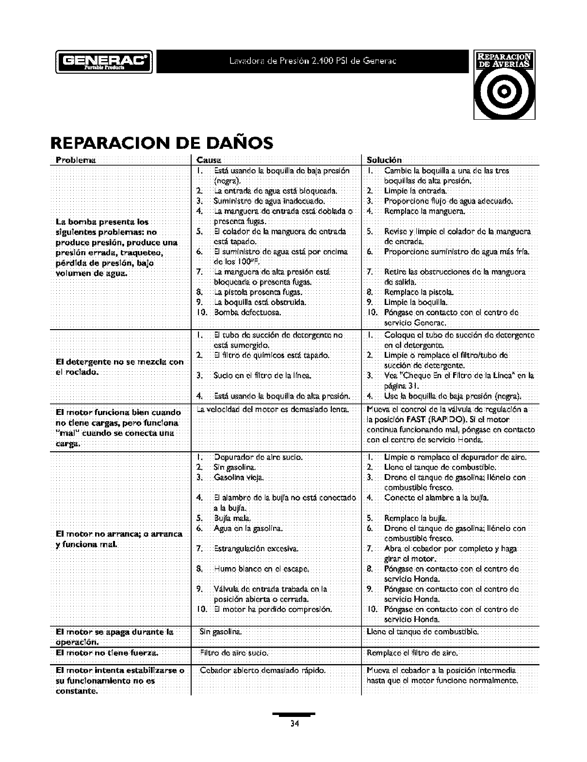
REPARACION DE DAI IOS
P_blem_ Soluci6n
IEstdusandoI_.b0quilla de baiapresi6n I Cambre I_.boquilla_.un_,dc_las t_s
boquilla_ d_ alr_presr6n
2 Limpiela ent_r_dm
3 Sumrnistrodc agUainadccu_.do. 3 PropOr¢(one ilUiode agua_d_CU_do
4 _ m_.ngucr_d_ entr_da es_ d0bl_da 0
L_ bomb_ presenr_ i0s J pr_s_nm
s_guienr.esproblemas: no 5E!¢o!adorde !amangu_ de cn_da 5 Rev!s_ylimpic__1¢olad0r"d_ lam_ngue_
produce presidn, produce una d_ encrad_L
presi_n errad_, tra.quer.eOi ElSurn(n(Stro de _gU_._st_ p0r en¢im_. 6 Prop0r¢i0n_ _urnin[str0 d_ agua m_s_r[ai
d_10sl00_F. I
Volumen de =gu_ _ _ m_nguemd_ al_ p_s]_ nos_ 7 ROUte1_ 0bscrucci0nosde !amangu_r_
8_p(s_olapresen_afugas. 8i Remplac_la piscol_
9_b0quillaesr_ 0bst:ruidai 9 Limpiela b0quilla.
! E!rob0 d_ suc¢i6n de d_rg_nce no I COlOqUe el tubo d_ suc_(6nd_ dc_ergent;_
es_ sum_rgido end d_t_rg_n_.
2 El 2 Limpieo rempl_ce _1filtro/tUb0 d_
E! dete_ente n0 se mez¢!_ €0n 3i SUci0_n _1_il_rod_ ia ifn_ 3 ve_ !'_heque Enel Fiitro d_ la Lin_a, _n i_
p_[n_ 31
4 Estdusan_ I_ boquil!ade a_ pr_s!6n. 4 Use la boquill_ de b_j_preSi6n(negro)
El nnol:or funcion_ bien _u_ndo Ye!°€!d_ddo! mc_or es dema_!ado!_n_ P_u_w d ¢oncro! d_ la v_!_Jl._d_ rP..gu!_ci_na
I LImpi__r_mplac__1d_purador d_ _ir_,
2sin gaS01(na_ 3 Dr_n_ e! t_nquede gasoline;1!6ndoCon
combustibl_ _r_$co.
4i Elalambr_ de I_.bui_an0 _std conecc_do
a!a bujfa. I
5Buji_m_!a_ 5i Rornplac_la bujia_
6 A_ua _n la _as0]in_. 6 Dren_ el t_nquede gas01in_:II_nd0 c0n
El _of_r no _u_an¢_ o_nc_
8: P6ngas_en cont.€to con _1centro d_
I' ServiCi0H0nda_
9V_!VUI__ _nt_da tmba_ _n !a 9P6ngas_en €on_¢to ¢0n _1centro d_
posic!bnab(ert_0 cerr_da se_ido Honda.
I0. Elmotor h_.perdido 10. P6ngaseen€0nt_ctocon _1centre de
E! _0tx:_r Se =paga du_nte !_ s!n ga$0!in_ L!ene_1_nqu_ d_ ¢_mbusdbl_
0peP_c!0n, i
El nnob_r no _1enefuerza_ Filtrode air_ SUCiO.
El motor intenta es_ilizarse 0Ccb_dor _b(_0 d_masiador_pido I_ uev_.el ccbad0r a la p0s(ci6nintermedi_
I I
1
34
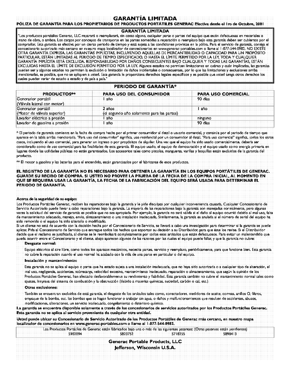
PGLiZA DE GARANI"|A _LOS PROPiETARiOS DE PRODUCTO$ PORR'AI"iLES GENERAC EfecLiv_ d_sde el Iro de OcLubre; 200i
GARANTiA LIM ITADA
!'LOSpr_du¢cos p0i't_u!esGetier_¢,I_I_Cr_r_r_ 0 _enlpl_r_; Sii__Osto _l._Ui_o,cu_.!quiei_i'te o p_rtes de! equip0 _e esc_i_del_e¢_ en ni_ePi_.[e$0
IT_n0 de 0bra; 0_b0S; Lo_ Carg0s p_r €0ncep_o de Cr"al_Spor_ en!Bs par_e_ S0rne_id_S _rep_r_¢i6n 0 reernp!_zo b_j0 est_ _r_nd_ _beli ser Cubiert_ p0r el
_ompr_d0r. [::s_ _r_i_i_ _ e_d_ pot Un cJei_ period0 de uem pot es_ Sujet_ _l_s _0i_diCi0neS pi_iSt_S enla p_liza. I_t_ el Servi¢i_ d_ g'_f_n_J_ €0i_Sig_ e[
€0n_esi0n_rio _ucor_d0 m_s Cerc_0 en nUes_ _ Iocali_d0_ de €0n_si0na_i0s en www_enei_€-p0r_b[esic0rn 0 II_e _1 1-877-5_-0982i _O E:<IST[::
OTP_ _NT[A E_PF[E_ LAS GA_dNTIA$ [IHPI_ICiTASi iNCL_ENDO AQUEL_ DE HERCANTIBiLiDAD O CAPACIDAD PA_ UN P_P{_SITO
PARTICULAIL ESTkN LIIVI[TADA$ AL PEKiODO DE TIDHPO £SPECIFICADQ, 0 HASTA I]1. L{IVliTE PERIVlITIOO PORLA L_ TODAY
GA_NTIA !H PI-{C!TA E_ _UIDA_ R_NSABILIDAD m R DA_OS CONSECUENTES BAJQ CUALQU!E RYTO DAS LAS GA_NTIA$i E:ST_N
ExCLU!DAS HASTA EL L[HITE DE ExCLUSI_)N pERHmDO POR L_LE_. A]gunOs e_mdCs me pe_n_ioe!1Jirllit-_i_rl_ _1__U'_rl{_O_ _lJ_l_ inIPJJ¢_d_i !_l__r_n_ _s
pueden se_ y _un0s es_dos no pe_i_en !_ _¢lusi6n _ I!m!l_t¢i_i_ de d_ in_i_ent_!es _ ¢0nsecuentes, por !o que !_ Ijmi_¢!0nes y_¢lu$[ones
iT_el_cion_#_l_, e_ p0S]ble, q_e n_ se _pliquen _ ustedi E$_1 _P_li_[_ I_ prop0_JQi_ dei'ecl_0S !e_le_ esp_¢ifi¢os yes p_Si_l_ que usted _n_ _s derechos los
CU=JeSpueden yaria_ de eS_d0 _esl_d_ _de p_is
PERiODO DE GARANTiA_
PROOUCTOS_ IPARA USO DEL _ONSUHIDOR PARA USO _OM ERCIAL
V_IVula I_.t_r_l €0n [ ]
_rvlOtor d_ v_lvula sup_ri0r)[ (d S_gundo _0 s01amen_e p_ra ]as
nin_uno
Lawdor d_ ga_01ina _ prosi6n [ i as0 90 dla_
El pe_i0do de _,'_r_'_ €0mien_ en i=__ch_ de €0rnpi_ heci_=_p0r el primer ¢0nsumid0r ai det_l oUSU_ri0 comerci=Ji 7€0nUn0_ p0r el pe_i0do de _iemp0
apare_een labia arri_ n!en_i_nada ilia n_ uso del €0nsur_id_ si_niPv:ai US0 residen_ia! P_r un €0r_urn!d_r amdet_!. ! Par_ US0 ¢_erciaL ' _i_[!ifi_ _d0$ I_s otm$
_0Si in¢!uyendo e! uso _rnerci_li pa_ gen_r_i, ui_ ingr_$_ 0 p_r pi_p_itos de _!qui!ei_ una veZ qU_ el _quip0 ha Sid_ UsadO €0rnerciaJrnen_i deberia set
¢onsider_do como deuso corner_i_l p_ra I_s _n_lidades de es_ t_t_ntla, B equipo us_do, el equipo de demos_raci6n yel equipo u_do como energ[_ primari_ en
]ug_res d0nde I_S u;!l!dades pQb!i_ nQ est_n _ar_nti_doSi L°s _ccesori0s _!es €0rn0 pi_I_S, rn_n_i v_r!l!as y _ui!!as est_n exdu!d0$ d_ la _rm_da del
EI motor __o!!n_ y 1_ _t_ r'f_s P_{3 el ence!ld!do, eS_l! _aPa!!_Jz_d_ po_ _1f_ric_nLe d_ e$_
E1 REGISTRO DIE LA GARAN'I'[A NO I=S NECESARiO PARA OB'I'ENIER LA GARANTiA IEN LOS I=QUIPOS PORT,_TiI_ES DE GENERAC_
GUARDE SU RI=CIBO DE COHPRA; $1 U$TED NO PROVIEE LA PRUIEBA DE LA FECHA DE LA ¢OHPRA INICIAL* AL HOH_NTO EN
_UE Sl= R_U!ERA USAR _GARANTIA_ LA FECFIA DE LA FABR!CAC!ON DEE EQUIPO SEI_ USADA PAPA DETERH!NAR I=L
PERiODO DE GARANT|A.
Acen_ de !a _tidad de SU equipo:
LOS Pr_dU¢_os Por_tileS Genei_¢, i_i_en ]_s {_p_racJ0iies b_j0 I_ _rai_[_ y [e pixie, disculp_ p0r ¢u_lquie_ inconvenien¢i;_ c_us_da. Cualquie_ c0ncesi0n_ri0
Servi¢i0 Au_or_t]0 pUede I[e_i _ _b_ rep=J_¢i0n_s baj0 I=-_ar_u_d_. L_ rr_7off_ de I_ _epu_¢i0n_s baj0 la _i_ntj_ s0n m_neja_[as n0n_almen_, pete _lgunas
veces J_soJic_d del servicio de _r_nd_ es pos]bJe que no se_ apr_piada; _r e_mplo, la _ar_ia no ser'_ v_l]da siel dal_o _Jequipo ocurri6 debido _Jm_J uso, l"_Jta
de rnan_en!rn!en_ _decuad0i man,J0, env!0i _lm_¢e!_m!en _ 0 un=- in_!_¢!6n !n_decu =-d_ sim!l_r_en_ !=-gaP_n_ es anul_d_ s! eI n_me ro d_ se!_=-Ide[ equipo h_
sid0 r'em_!d0 _e! equip0 !_=-_i_io =-!te{_i0 _ m0dific_d_ ,
Si un clien_ n_ es_ de _¢uer'd_ ¢0n i=_de¢isi6n he€! _=-P0r el C_ncesi0n_ri0 de _rv!¢!0i se I!ev;_r_ _ _b0 Un_inveS_!_ci_n p_r_ _ier.e_in_ $[ !_ _r_nti_ se p_e_e
apljc_r. P!da =-]c0ncesi_r!0 de se_i_io Queei__r_ue _dQS I_S hedi0s Ques0P0 _n Sud_iS]_ _SU D!SU ibU!d_r, I_r_ que @ste ]0S _ise, Si el D!S_ibU!dO
de¢id_ QUe _1 _¢l_m0 _ iUsrJflcad0,a! €lien_ se !e _rnb_l_r_ ¢0_p[et_J_ite pc_r,md0S _S _r_icul_s _u_ es_n defeC_s0S, P_r_ evi_r Uii rn_!ent_ndid0 que
pued_. 0cu_rir en_ el _0ncesi0n_i0 ).el €lient.ei _aj0 _p_recen _]_[Uii0S _el_s _0nes p0r 1_ Cu_l_ _1 equip0 puede t"_l_r_ y que [__ai_iit_
Equip0 eI@€_H¢0 _1 _iPe [i_rei €0m0 tod0S 10S_.i_t_S me_nic0si n_esita p_r_es, se_vici0 7 Peernpl_z0, peri_di_n_e, p_Pa que Cuncione _en. ESt__i_iit_
no cub re !a rep_r_¢i6n Cu_l!do eIus0 norm] I !_=-_¢_d0 con !_ Yid=-de un_ pa_e en ParticU!_r 0 deL
insr_l_ci_n y m_ncenimien_o:
ESt_ _n_d_-i!0$e _pl!c_ _! equip0 0 Parte que I!=-es_d_ suJe_ _un=-!i_t_l_l¢i61_ in_ldecu_d_ Quen_ I!=-_ sid0 _u_ri_d_ _ a cua!quier tip0 de alte_i6n, el
m_lu_ iiegligenci_ _cddent_s_ Sobrec_r_li Vel0cidad excesivai m_u_tenirnienEo inadecu_d0i rep_aci_n _ a[rn_¢e_i_mient_ qUe se_n I_ opini_it de 10s
ProdU¢_S P_i!es Gene r_c, !_n _l_cta_O desfav_r_b!ernen_e su rendil_iento y _!lid_d • Es{_ _rantJ_ _mb!@n r_ cubre el mantenim!en _norl_a! _les ¢OmO
_UsteS, li_piez_ del s]s_m_ de ¢0mbusti_n y la 0bstruc¢i6n (debido ama_eri_ quimiCas_ SU¢iedad, Car_i O c_li et_i_
O_Pa_ _¢[u_ion_s=
•al_bi_n Seencuei_0_n excluidoS _e est_ g_rm'_ el des_ste de ]0S _icUi0s _les €orno, €one¢_doresi i_e_i_0r_s _e a¢_itei €0rre._si anillos 0,
en!p_que de I_ bornb_ i _¢i I_S b0mbas que se h_n tun¢i0n_r 0mab_Jar $ii_ _U_ 0_0S _ mal[unc!0narn!en_$ Que resul_! de a_¢_ienLe$i
m0d_i¢_ci_nes, =Jtei_¢i0nes, un se _i€]o ]n_d_adoi c0_lamien_
L_ garanr=_ se encuentta d!sp0nib!e _!a_nente a cr_.v_s de los _0n¢_s!0naH0s de servi¢ios aucor!zad0 s pot 10S productos Port_lt_!es Generic.
I=st_ gar_i_ no _ap!i¢_l _1 se_i¢i0 proveniente de Cualqu{er otn=
Used pueds ub!¢&r su C0ncesion&ri0 de Servido AuLor!zado de lOS produ¢ r_s Porr_.i!ss de Genera€ m _s CePcan_ en hUeS tPo m_P a
!_liz_or de ¢oncesion_os en v_w.gene_poM_b!es.¢om 0 I!ams a! !_877_544_0982i
Ge.!er 0
.J_cff'ersO n__$€on_! n
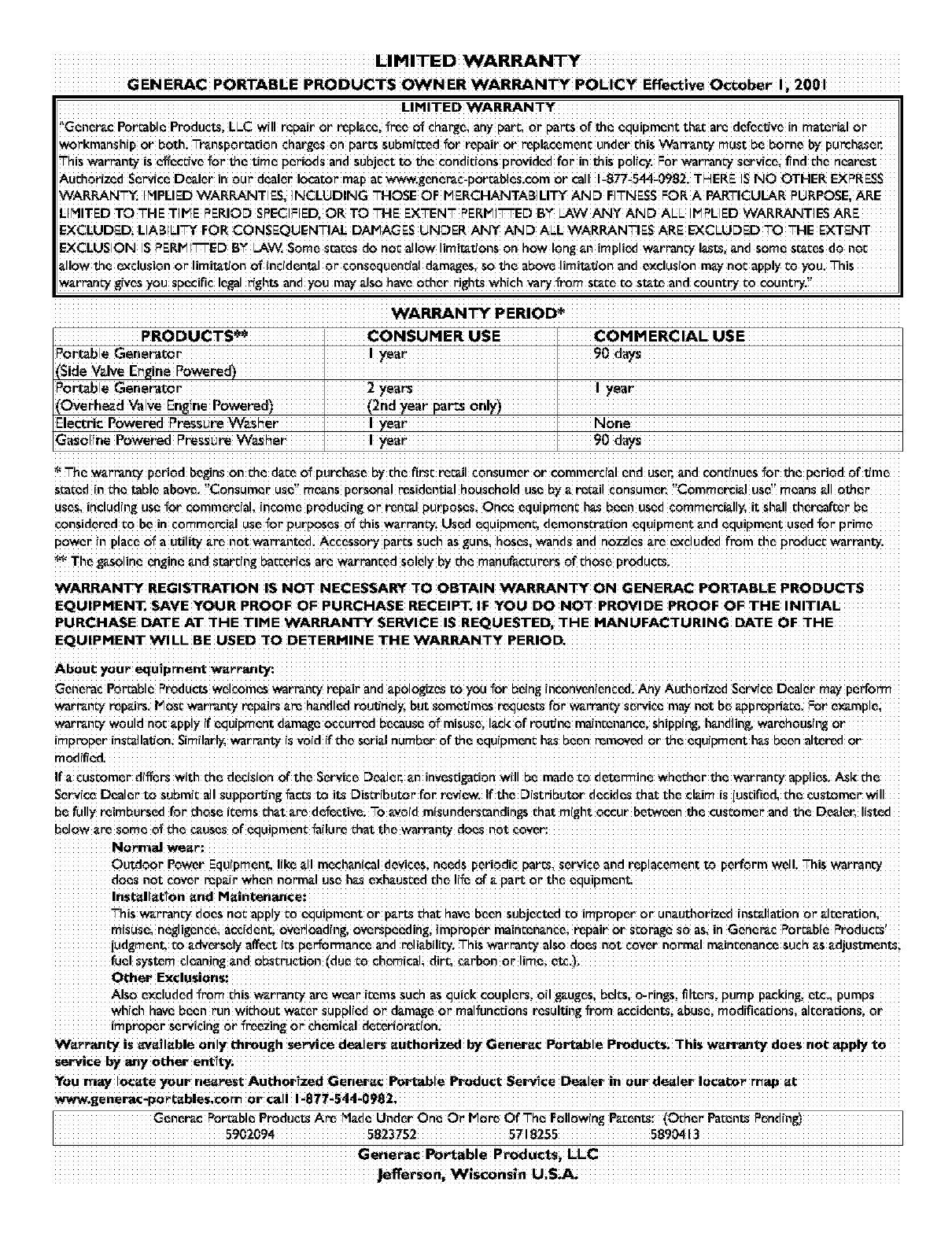
GENERAC PORTABLE PRODUCTS OWNER WARRANTY POLICY Effective October I_ 2001
!'Generic P0_ble ProdUctsi LLC Wr!lrepairor replace,l_e 01_ehargei any parc_Or pares Ofthe equipment tha_are d_fcctJye in matori_l or
workmansh!p or both; Transportndon charges 0n paressubm!ccedfor _air or rep!acemen¢ underthis Wa_nty must be borne by purch_er.
This war_ntY is effective _or theUme Periodsand subject to the c0nd!c!0nsprovided for in this Pol!cy. FOrwar_n_ sorv!ce_find the nearest
Auch0r(zed se_!ce D_!er in our dea!er, io_tor, map acww_-generac-p0rr'_bles C0m0 r caII !_8_i544_0982 , r_ERE IS NO OTHER EXPRESS
WARRAN'_. IMPLIED WARRANTIES. INCLIJDING "THOSEOF PIERCFIANTABILI'r'( AND FITNESS FOR A PARTICULAR pIJRPOSEiARE
LIMITED TO "THETIME PERIOD SPECIFIER.OR TO -FIE EX'-EN'T" PERtainED BY LAW AINY AND ALL IPIPLIEDWARRANTIES ARE
EXCLUDED LIABIL!_ FOP-CONSEQUENTI_ DAPI_ES UNOER _Y AND ALL WARRANTIES ARE EXCLUOED TO'THE EXTENT
EXCLUSION IS PERPII'T'-EDBY LAW.Som_ s_Ces do nocallow limitationson how long an impliedw_rran_ lasts. _nd som_ sr._cesdo noc
_-I!owthe exclu!ion or I!mitatJ0no1_!nddenta! 0r ¢0nsequen0a! damages,so the above I!mitatJ0nand exc!usion may n0c app!y co you. This
warmn_ gives _0U SPeCifiC!e_a!r_g_ and X0Umay a!S0 have 0Char rights which _ _m state c° st_ and c0un_ co country.?
WARRAN_ PERIOE
PRODUC'rSe_ I CONSUMER USE I COMMERCIAL USE
Pebble I year' 90
(Side Valve I I
Po_ble Gene_t0r I2years I I year
(overhead ValVe Engine P0wer_d_ I(2nd year pars 0nly)J
Electric Powered Pressure W_s_er" I Iyear I None
G_oli,e Powe_d F'_SS__ w_her' Ii _ar' I90 day_
:_The w_rrant¥ p_riod begins0n che d_c_O_pUrChaSeby the first r_il consumeror €ommercialend user._nd continues_or che period Of time
s_ccd in che table ab0¥_. !'C0nsumer usa!' means pers0na! residenua!h0useheld use bya r_-cailconsumer.!!C0mmercia! use!' means _.1!other
uses, including usa for c0mmerc!a!_income producing or renal purposesOnce equ!pmen¢h_ been used€0remedially, it sh_l!thereafter be
consideredCObe!n €0mmercia!use_o_Purposes_ =hiswarrantT,Used equipmenc, dem0nsCradon equ!pment and equipment usedfoe
Power !n p!ace 0_aOUli_ a_ n0t_ t_d ACcess0ry par_ssud_as gunsi hoseSi _,dS and n0zzles _-ree_dud_ f_m _e P_ducc _rt_nty ,
_--_The g_-so!ineengine and star_!ngba_er!es are W_.t'ran_edsolely by _hemanufacturers 0__hose p_du_
WARRANI_ REGISTRATION I$ NOT NECESSAI_ TO OBTAIN WARRANTY ON GENERAC PORTABLE PRODUCTS
EQU!PMENT_ SAVE YOUR PROOF OF PURCHASE RE_EIP'r. !F YOU DO NOT PROVIDE PROOF OF THE INITIAL
PURCHASE DATE AT THE TiME WARRANW SERVICE iS REQUESTED, THE MANUFACTURING DATE OF THE
EQUlPHENT WILL BE USED TO DETERHINE THE WARRANTY PERIOD,
Abou t YOUr eq u!pnnent w_r _anL'y:
Generac Pebble P_ucts welCOmes_rmn_i repair and _p0!0gizes to_u _or beinginc0nveni_nced. _y AuthorizedServ_€_Dealer may perfo_
war_ repairs. PIoscwarra_ repairsam h_ndled r_ulJne!y,butsomc_dmesr_ues_ for _nt_i ser_!¢emay net be appropriate. _ e_mplei
war_n_i wouldnoC_pp!y !f equ(pment damageoceU_ because_ misuse. I_ckof routine maintenance,shiPpingih_ndling. warehous!ngor
!raPt°Per in_!atJ0n similat_ _t'ran_ !svoid i{ the seria!number of be equipmen_ has been _m_ 0r t_e equ!pment hasbeen a!te_ 0r
!facuscomer,diffe_W(Chtheded_ior'OftheServi_eD_e_ an !nveSd_cion_il!bemade _0_ete_ine_h_her _ _rran_:_applies,
so,ice Dealer't° subm!c al! supp0_ng fa_ _ its D!sCr{bUtor.fo_ review. !fth_ D!Stributor decides _hat tl_e ClaimiS iusdfi_d, the cus_mer. _! I
be fully reimbursed forchOSeic_mschat _.rede_eCtiveiTo _void misunderstandingschat might 0ccur between_e customer and the Dealer, li_ted
be!OWare some c_che C_UsesOfequipm_nc fai!ure Cha_chewat'rantydoes n0t cover:
Outdoor Power Equ!pment. !!k__11mechan!ca!devicesineeds periodic par_, _erv!ee andreplacement to perform wd!. This w_rPan_
dons n0t C0vermp_.(rwhen norm_.lUSaha_exhausted che IffeOf
This warran_ does n0c apply c0equ!pment or parts chat.have been subjected_0 improper OFun_uchorized!nsCal!ati0n 0F alcerati0n_
misusei negligenceiaccident. 0ved0ading, 0verspeeding_improper maincen_.nceirepair or Scorage_0 aS_]n Generac Portable Produces!
iud_men_ co a_et.sely affect !csperfo_ance and _!iabiiiui •_his wat'ran_Ya!S0 doesnot cover n0r.maI_incenanee SUChZS_Juscmentsi
fuel sTst_m Cleaning_nd Obstruction(du_ _0 chemicalidirc_
O_her Exclusions:
Ais0 _xc!uded _rom th!s _rmn_ a_ _ear. i_ms Such asqUi_k C0UPler_i0!! gaugesibel_, 0trin_sifi!te_ Pump p_kin_ ctciipumps
which havebean run wi_h0ut w_cer supplied or d_.mageOr malfun_i0n_ resultingfrom _ccidents:abusei modiflc_donsi a!c_rauonsior
imp_per, so,icing 0r freezing 0r.
W_-_r_L7 iS_l_ble 0nly throu_ hse_¢e deale rs _uch0rlzed bY Genera_ P_able Pr°ductsi "this Wan'_n_ does nat apply
Service
YoU may locate your nearest Authorlzed Genera€ Portable Product Service Dealer in Our dealer !0catx)r map
www.generac-P_r_b!es,e0m or cal! !-877-$44-0982i
Oenerac Po_b!e prodUCtSAre Hade Under One o_ P10reOf -ha F01!0w!ngPa_ent_: (O_her Pa_ent_
Gene_a¢ _able P_du¢%s_
....................................................................... Jefferson, W_scons_ n U,S,A, .......................................................................
