General Dynamics Broand NODEBAJ1 NODE B Base Station, Model AJ User Manual Legal Terms Governing This
General Dynamics Broadband, Inc. NODE B Base Station, Model AJ Legal Terms Governing This
Manual

“IPWireless”
Model AJ Installation Manual
(First Generation NodeB)

Node B Installation Guide
DRAFT
17 July, 2001 IPWireless Proprietary
IT IS ILLEGAL TO MAKE COPIES OF THIS DOCUMENT WITHOUT EXPRESS PERMISSION BY IPWIRELESS 1
DOCUMENT INFORMATION
IMPORTANT
Please review the terms below as your review and/or use of this document is subject to such terms. Your review and
use of this document means that you agree to such terms. If you do not agree to the terms below, immediately
inform us that you do not agree, return this document to us, and do not conduct any of the activities described in this
document.
Legal Terms Governing This Document
About the Information Contained in the Document: IPWireless and its subsidiaries and other affiliates
(collectively, "IPWireless") have used reasonable efforts to help ensure that the information and specifications
published here are current as the date of publication of this document. However, we are continuously improving and
adding features to our products and systems. Accordingly, IPWireless reserves the right to change the information
in this document without prior notice. You may verify any product or system specifications in this document by
contacting our office. IPWireless shall not be liable for technical or editorial errors or omissions which may occur
in this document.
The Content of the Document: This document is protected by the copyright and trade secret laws of the United
States and other countries. This document contains proprietary information of IPWireless and this document and its
contents shall not be disclosed to anyone except IPWireless or used except in accordance with these terms. It may
not be reproduced, distributed or altered in any fashion without the express and written consent of IPWireless.
"IPWireless" is a trademark of IPWireless, Inc. and may be registered in the U.S. and other jurisdictions. Certain
other marks used in this document belong to their respective owners.
Disclaimer of Warranties: Although IPWireless has used reasonable efforts to produce this document, THIS
DOCUMENT IS PROVIDED “AS IS” AND IPWIRELESS EXPRESSLY DISCLAIMS ANY AND ALL
WARRANTIES, EXPRESS OR IMPLIED, CONCERNING THIS DOCUMENT AND THE USE OF THIS
DOCUMENT, INCLUDING, WITHOUT LIMITATION, ANY WARRANTY OF MERCHANTABILITY,
FITNESS FOR A PARTICULAR PURPOSE OR AGAINST INFRINGEMENT.
Limitation of Liability: IN NO EVENT WILL IPWIRELESS BE LIABLE FOR ANY DIRECT, INDIRECT,
INCIDENTAL, SPECIAL OR CONSEQUENTIAL DAMAGES (INCLUDING, WITHOUT LIMITATION,
LOST PROFITS), ARISING OUT OF OR RELATED TO THIS DOCUMENT AND THE USE OF THIS
DOCUMENT, UNDER ANY THEORY OF LIABILITY, WHETHER IN AN ACTION IN CONTRACT, STRICT
LIABILITY, TORT (INCLUDING NEGLIGENCE) OR OTHER LEGAL OR EQUITABLE THEORY, EVEN IF
IPWIRELESS KNEW OR SHOULD HAVE KNOWN OF THE POSSIBILITY OF SUCH DAMAGES.
Indemnification: If you are not an employee of IPWireless, you agree to indemnify, defend and hold IPWireless
harmless from and against all claims, damages and costs arising from or relating to your failure to follow fully the
instructions and requirements (including these terms) set forth in this document.
Our Relationship: Nothing contained herein shall be construed as creating any agency, distributorship, partnership,
or other form of joint enterprise between you and IPWireless. You are agree not to make any representations on
behalf of IPWireless or otherwise assume for IPWireless any other liability in connection with any IPWireless
product or service.
In General: These terms supersede any and all prior or contemporaneous written or oral agreements with regard to
the subject matter of these terms. A failure to enforce these terms shall not be considered a waiver of any rights.
These terms are governed by California law, without regard to its choice of laws.

Node B Installation Guide
DRAFT
17 July, 2001 IPWireless Proprietary
IT IS ILLEGAL TO MAKE COPIES OF THIS DOCUMENT WITHOUT EXPRESS PERMISSION BY IPWIRELESS 2

Node B Installation Guide
DRAFT
17 July, 2001 IPWireless Proprietary
IT IS ILLEGAL TO MAKE COPIES OF THIS DOCUMENT WITHOUT EXPRESS PERMISSION BY IPWIRELESS 3
TABLE OF CONTENTS
IMPORTANT.................................................................................................................................... 1
LEGAL TERMS GOVERNING THIS DOCUMENT ......................................................................1
1 OVERVIEW..............................................................................................................8
2 PRE-INSTALLATION...............................................................................................9
2.1 Installation Check Card ................................................................................................... 9
2.2 (Step 1) Pre-Installation Site Check................................................................................ 9
2.3 (Step 2) Parts Shipped .................................................................................................... 10
2.4 (Step 2) Tools Required for Installation ....................................................................... 10
3 (STEP 3) MOUNTING THE NODE B BRACKET...................................................11
3.1 WALL MOUNT.............................................................................................................. 12
3.2 POLE MOUNT ............................................................................................................... 13
3.3 RACK MOUNT .............................................................................................................. 14
4 SITE PREPARATION FOR NODE B INSTALLATION..........................................15
4.1 (Step 4) Conduit Installation.......................................................................................... 15
4.2 (Step 5) Antenna and Coax installation........................................................................ 15
4.3 (Step 7) GPS..................................................................................................................... 16
4.4 Service Cover Area ......................................................................................................... 16
4.5 (Step 9) External Alarms................................................................................................ 17
5 (STEP 10) PHYSICAL INSTALLATION OF THE NODE B ...................................18
5.1 Placing the Node B into the Rack.................................................................................. 18
5.2 Service Area Interfaces................................................................................................... 23
5.3 (Step 6) Grounding Installation and Inspection........................................................... 24

Node B Installation Guide
DRAFT
17 July, 2001 IPWireless Proprietary
IT IS ILLEGAL TO MAKE COPIES OF THIS DOCUMENT WITHOUT EXPRESS PERMISSION BY IPWIRELESS 4
5.4 Cable Clamp Seal............................................................................................................ 25
5.5 Connecting Power to the Node B................................................................................... 25
5.5 Connecting Power to the Node B................................................................................... 26
5.6 Backhaul Connections to INC........................................................................................ 27
5.7 Alarm Connections ......................................................................................................... 30
5.8 Replacement of the Seal cable clamp ............................................................................ 31
5.9 Conduit Pivot Bracket Securing.................................................................................... 32
5.10 Closing the Door and securing the NodeB.................................................................... 32
5.10 Closing the Door and securing the NodeB.................................................................... 33
5.11 GPS................................................................................................................................... 34
6 (STEP 11) POWER UP AND INITIAL SETUP OF NODE B ..................................35
8 (STEP 12) SOFTWARE INSTALLATION..............................................................37
9 (STEP 13) ON AIR FINAL CHECK........................................................................37
10 OPERATION & MAINTENANCE........................................................................37
10.1 Maintenance .................................................................................................................... 37

Node B Installation Guide
DRAFT
17 July, 2001 IPWireless Proprietary
IT IS ILLEGAL TO MAKE COPIES OF THIS DOCUMENT WITHOUT EXPRESS PERMISSION BY IPWIRELESS 5
LIST OF ILLUSTRATIONS
CAUTION SIGNS.......................................................................................................................... 6
NODE B SPECIFICATIONS......................................................................................................... 8
NODE B FACE............................................................................................................................... 8
INSTALLATION CHECK CARD................................................................................................. 9
PARTS CHECK............................................................................................................................ 10
TOOLS REQUIRED PHYSICAL INSTALLATION.................................................................. 10
POLE MOUNT ASSEMBLY....................................................................................................... 13
RACK MOUNT ASSEMBLY ..................................................................................................... 14
NODE B PATCH PANEL............................................................................................................ 18
NODE B PATCH BOARD ENGINEER SPEC........................................................................... 35
INDICES
APPENDIX B – BACKHAUL SPECIFICATIONS.................................................................... 39
APPENDIX D – NODE B SPECIFICATIONS ........................................................................... 41
AIR INTERFACE......................................................................................................................... 41
Node B Installation Guide
DRAFT
17 July, 2001 IPWireless Proprietary
IT IS ILLEGAL TO MAKE COPIES OF THIS DOCUMENT WITHOUT EXPRESS PERMISSION BY IPWIRELESS 6
Precautions
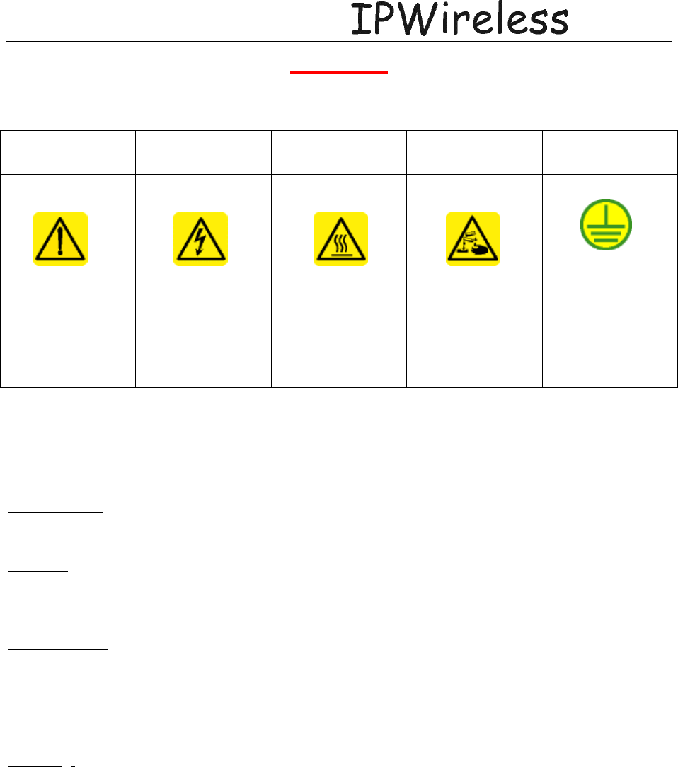
CAUTION SIGNS
GENERAL
WARNING ELECTRICAL
HAZARD BURN/HEAT
HAZARD CORROSIVE
MATERIALS GROUND
GENERAL
SAFETY
PRECAUTION
HIGH VOLTAGE:
Direct contact with
these areas will
result in severe
physical harm and
property damage
HEAT: Direct
contact with this
surface will result in
severe burns
CORROSIVE:
Direct contact with
this surface will
result in chemical
burns
GROUND: Site for
grounding
equipment
These cautionary signs are used on the physical equipment and throughout this manual. For safety of personnel and
protection of equipment observe these precautions when installing, operating or servicing the equipment and
surrounding areas.
Electrical
Power Supply – cord fitted for AC or DC. DO NOT adapt to a different configuration.
Power supply circuits carry high voltages. Remove rings, watches, and other jewellery before
working with this type of equipment.
Batteries – Installation of this equipment requires working with lead acid batteries. These
batteries present chemical, electric and gaseous hazards. Batteries are not supplied by IPWireless
for the Node B equipment although UPS systems may be coupled with the device in order to
provide back up power in case of power outages.
Modifications: DO NOT modify this equipment. This equipment has been certified by the
FCC in the configuration in which is has been shipped to the user. Any changes to this
equipment made by the user could invalidate the certification and the ability of the user to
operate this equipment.
Physical
Weight – Each node B weighs 25 pounds. Precautions should be taken, depending on the
installation site conditions, in lifting and hoisting the device. Generally one person will be able to
install the unit at the site.
Spurious Emissions
This equipment has been tested and found to comply with the limits for a Class A digital device,
pursuant to part 15 of the FCC Rules. These limits are designed to provide reasonable protection
against harmful interference when the equipment is operated in a commercial environment. This
equipment generates, uses, and can radiate radio frequency energy and, if not installed and used
in accordance with the instruction manual, may cause harmful interference to radio
communications. Operation of this equipment in a residential area is likely to cause harmful

Node B Installation Guide
DRAFT
17 July, 2001 IPWireless Proprietary
IT IS ILLEGAL TO MAKE COPIES OF THIS DOCUMENT WITHOUT EXPRESS PERMISSION BY IPWIRELESS 7
interference in which case the user will be required to correct the interference at his own
expense.
Environmental
There are different precautions to take within each environment. Specific precautions are listed
in the installation section for that environment.
Node B Installation Guide
DRAFT
17 July, 2001 IPWireless Proprietary
IT IS ILLEGAL TO MAKE COPIES OF THIS DOCUMENT WITHOUT EXPRESS PERMISSION BY IPWIRELESS 8
1 OVERVIEW
Node B is the European Technical Standards Institute’s (ETSI) name for the radio base station.
The basic function of the Node B is to convert 100 Base T packet data into the UTRAN TD-
CDMA air interface used between the Node B and the 3G Modem. The Node B can be
configured to operate in configurations ranging from a single sector or omni mode, up to a 6
sector arrangement. One Node B is required for each sector of coverage, in the case of an omni
configuration one Node B will be required. The Node B is controlled by an INC (Integrated
network Controller) Generally co located at the site in a separate cabinet.
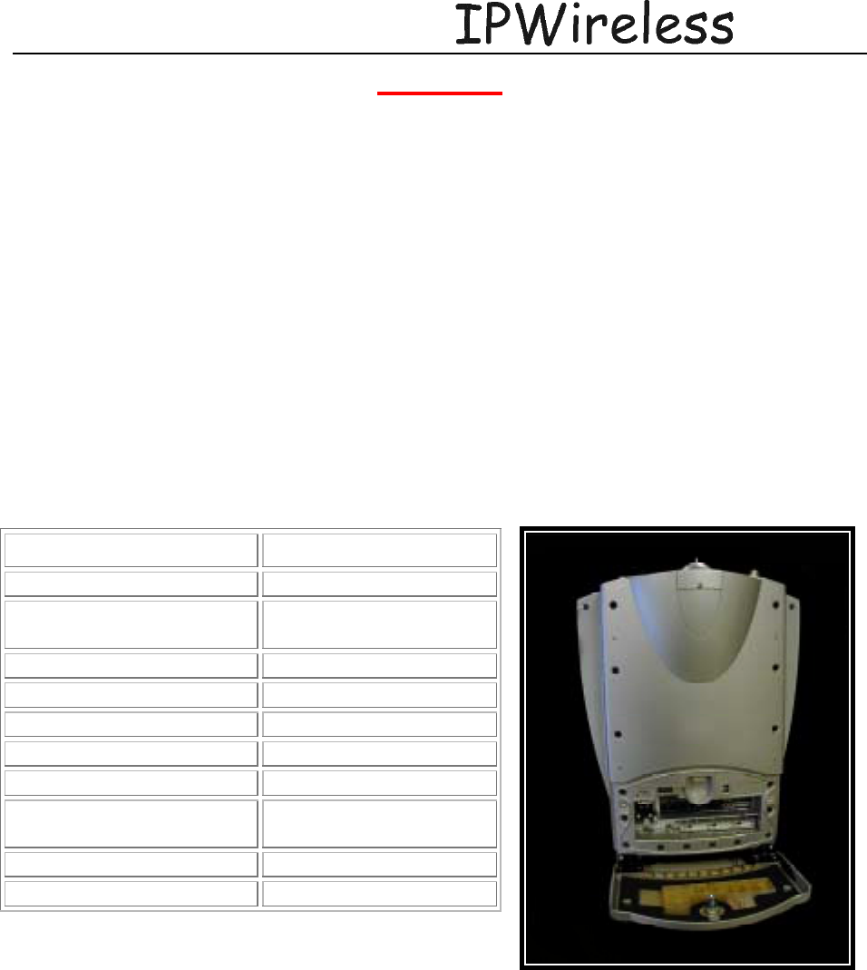
NODE B HIGH LEVEL SPECIFICATIONS
NODE B FRONT VIEW
Unit Specification
Measurements 16” H x 12” W x 5” D
Weight with mounting
Bracket 40 Pounds
Frequency 2500 – 2686 MHz
Power output +34 dBm
Power Consumption 300 Watts max
Input Power 110 VAC or -48 V DC
Heat Dissipation 184 Watts
Ambient Operational Temp
Range -40ºC to +55ºC
Cooling Convection
Weight 42 lbs.
Node B Installation Guide
DRAFT
17 July, 2001 IPWireless Proprietary
IT IS ILLEGAL TO MAKE COPIES OF THIS DOCUMENT WITHOUT EXPRESS PERMISSION BY IPWIRELESS 9
2 PRE-INSTALLATION
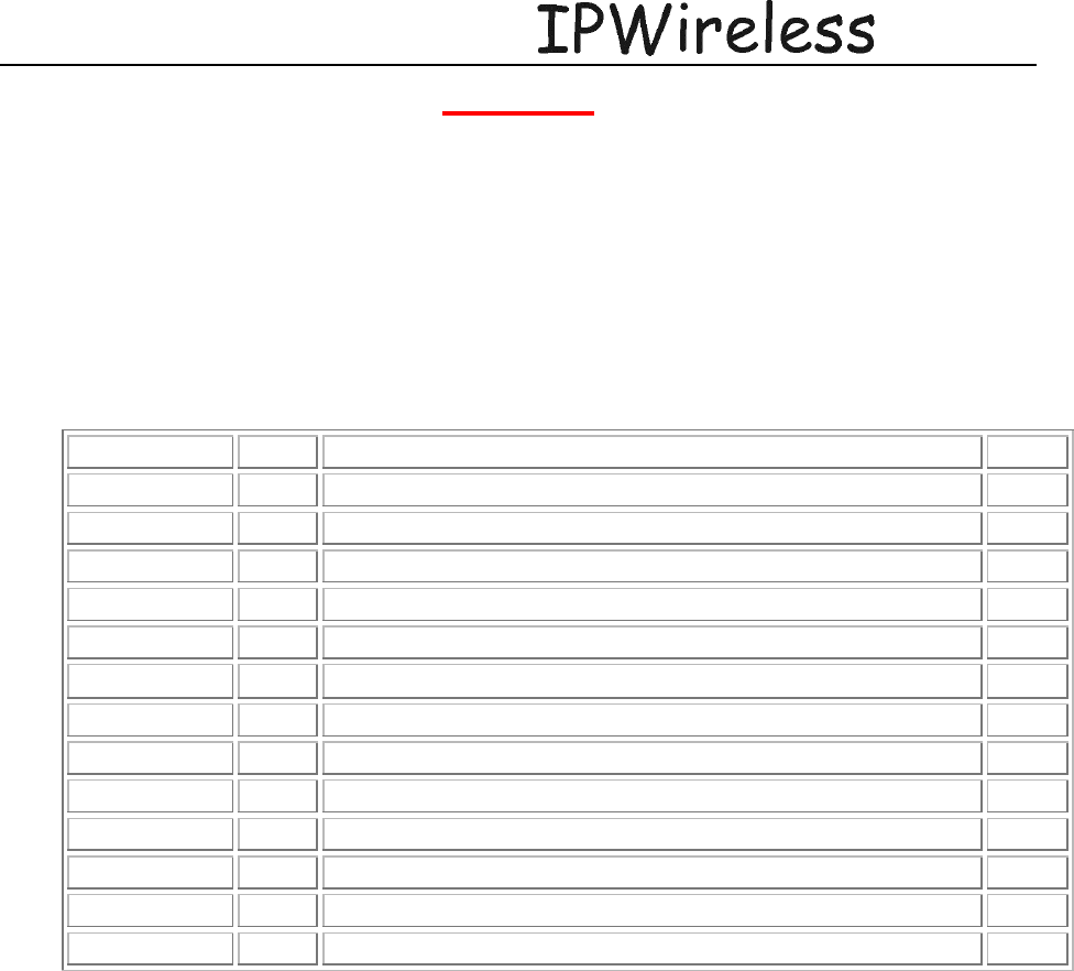
2.1 Installation Check Card
The following steps should be taken during the installation process in order to ensure safe and
timely installations.
Initials/Date Step Action Page
1 Perform pre-installation site check
2 Parts shipped/tools required
3 Install Node B mounting bracket
4 Install conduit for power and INC connectivity
5 Install Antennas and Coax
6 Grounding installation and inspection
7 Inspect site for GPS line of site
8 Install 100 BaseT connections between INC and NodeB
9 Local Alarm Connections
10 Physical installation of Node B
11 Power up and Initial setup and test of Node B
12 Software installation
13 On Air final check
2.2 (Step 1) Pre-Installation Site Check
1. Review site construction drawings to determine if site was constructed according to the
drawings
2. Review drawings and actual installation to determine location of Node B installation.
3. Check availability of electrical connections
4. Review if construction is completed to the point that it is safe to install the Node B.
Node B Installation Guide
DRAFT
17 July, 2001 IPWireless Proprietary
IT IS ILLEGAL TO MAKE COPIES OF THIS DOCUMENT WITHOUT EXPRESS PERMISSION BY IPWIRELESS 10
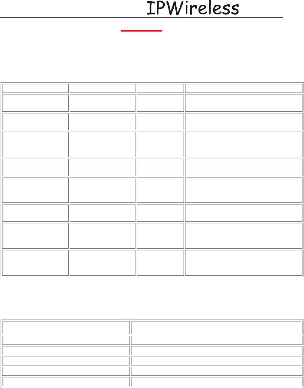
2.3 (Step 2) Parts Shipped
Use this checklist to check quantity and quality of parts as they are unpacked
PARTS CHECK
Part Name Description Amount Quality Checks
Node B Assembly 1 per sector Check shipping container for damage
and if quantities are correct
Bracket Assembly Node B mounting
assembly 1 per Node B Check shipping container for
damage, quantities, and type
Power Availability -48Volt or 110
VAC 1 connection
per Node B Check to see if power cabinet is
installed and the correct amount of
power connections are available
Alarm Contacts Dry contacts for
external alarm Check to see if external alarms for
lights, intrusion, fire, etc are available
Antenna Node B Transmit
and receive
antennas
2 antennas
per Node B Check box for damage. Check to see
if quantity is correct.
Connectors Antenna, Power,
grounding Ensure all connectors and quantities
are available for installation
Cables 100 BaseT, power,
coaxial cable,
jumpers
Ensure all cables are available and
that they are not damaged
Grounding Lightning
protection and
grounding,
2 AWG stranded copper
2.4 (Step 2) Tools Required for Installation
In addition to standard construction equipment, you should have the following on hand prior to
installation:
TOOLS REQUIRED PHYSICAL INSTALLATION
Tool Description
Voltmeter Fluke meter
Wiltron Sweep test
Basic telecommunications tool kit Includes screwdriver, socket wrenches, etc.
Crimper RJ 45 crimper connector
Node B Installation Guide
DRAFT
17 July, 2001 IPWireless Proprietary
IT IS ILLEGAL TO MAKE COPIES OF THIS DOCUMENT WITHOUT EXPRESS PERMISSION BY IPWIRELESS 11
3 (Step 3) MOUNTING THE NODE B BRACKET
There are three ways of installing the Node B – Wall, Pole and Rack Mounts.
This section explains the three different mounting types with the installation and powering
procedure for each type of mount.
PRECAUTIONS
The following precautions and checks are applicable to all mounting types.
Leave blanking plugs over all connectors until they have been connected to the appropriate
cabling. These plugs are specially fitted to keep moisture and contaminates out of the unit.
Connectors have been manufactured to fit their specific cables. Do not modify or force
connectors.
Check Site Plans for engineering approval.
Node B Installation Guide
DRAFT
17 July, 2001 IPWireless Proprietary
IT IS ILLEGAL TO MAKE COPIES OF THIS DOCUMENT WITHOUT EXPRESS PERMISSION BY IPWIRELESS 12
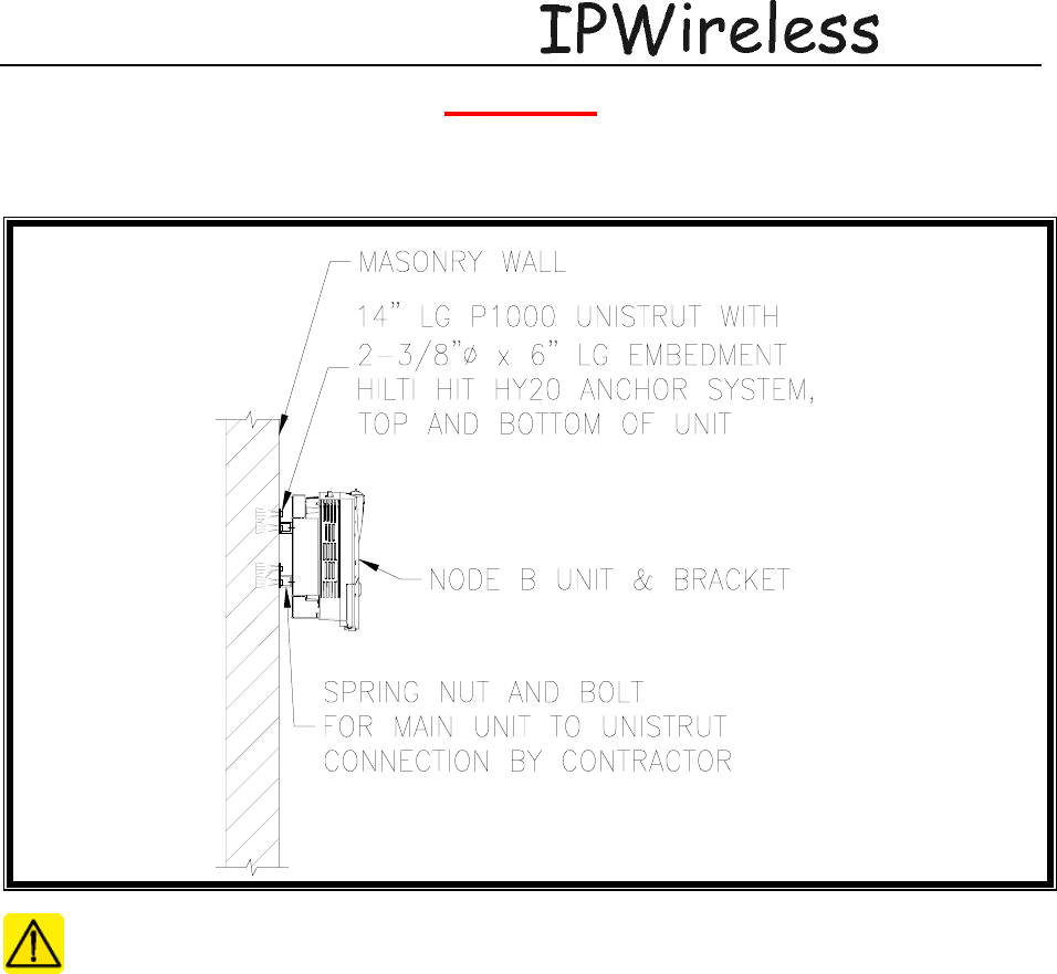
3.1 WALL MOUNT
WALL MOUNT ASSEMBLY
General Safety Precautions:
• Wall construction is able to support the weight of the unit assembly.
• Proper grounding
3.1.1 Mounting Considerations
Consider the earthquake zone requirements for the given site being considered. Ensure that the
mounting location complies with these considerations.
Review the GPS installation guidelines to ensure that the location will allow proper operation of
the Node B. I.e. a Southern Exposure is required for outside installations and a remote GPS
antenna or GPS repeater will be necessary in areas without a southern exposure or indoors.
Node B Installation Guide
DRAFT
17 July, 2001 IPWireless Proprietary
IT IS ILLEGAL TO MAKE COPIES OF THIS DOCUMENT WITHOUT EXPRESS PERMISSION BY IPWIRELESS 13
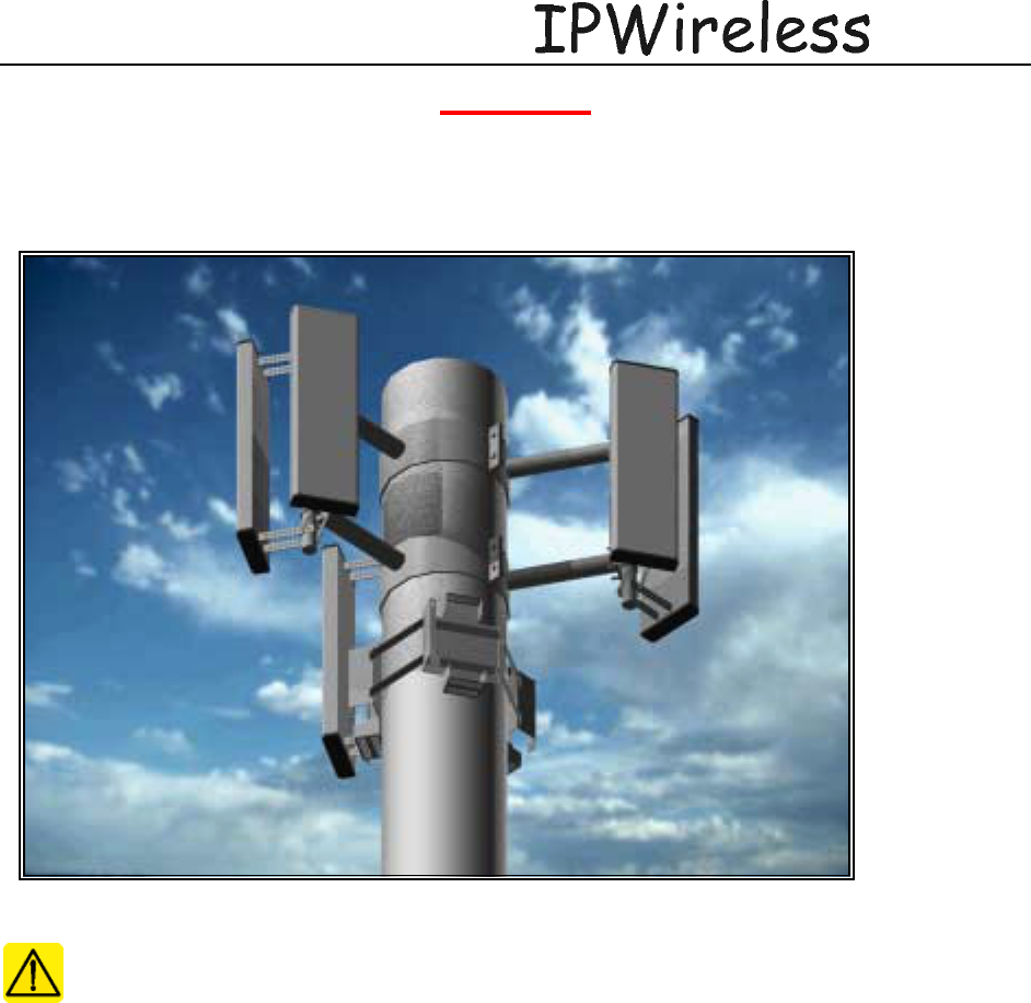
3.2 POLE MOUNT
POLE MOUNT ASSEMBLY
Illustration 3 shows antenna and mounting brackets fixed on an aluminum type pole.
General precautions –
• Do not install in winds over 40 Mph.
• Do not install when lightning is closer than 2 miles.
• Do not attempt to install in rain.
3.2.1 Mounting Considerations
Consider the earthquake zone requirements for the given site being considered. Ensure that the
mounting location complies with these considerations.
Review the GPS installation guidelines to ensure that the location will allow proper operation of
the Node B. I.e. a Southern Exposure is required for outside installations and a remote GPS
antenna or GPS repeater will be necessary in areas without a southern exposure or indoors.
Node B Installation Guide
DRAFT
17 July, 2001 IPWireless Proprietary
IT IS ILLEGAL TO MAKE COPIES OF THIS DOCUMENT WITHOUT EXPRESS PERMISSION BY IPWIRELESS 14
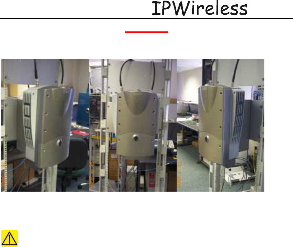
3.3 RACK MOUNT
RACK MOUNT ASSEMBLY
General Precautions
3.3.1 Mounting Considerations
Consider the earthquake zone requirements for the given site being considered. Ensure that the
mounting location complies with these considerations.
Review the GPS installation guidelines to ensure that the location will allow proper operation of
the Node B. I.e. a Southern Exposure is required for outside installations and a remote GPS
antenna or GPS repeater will be necessary in areas without a southern exposure or indoors.
Node B Installation Guide
DRAFT
17 July, 2001 IPWireless Proprietary
IT IS ILLEGAL TO MAKE COPIES OF THIS DOCUMENT WITHOUT EXPRESS PERMISSION BY IPWIRELESS 15
4 Site Preparation for Node B Installation
4.1 (Step 4) Conduit Installation
Conduit is typically required between the INC and the Power source. In the case of the outdoor
installation the INC and power source are housed in the same cabinet. Power and Ethernet cables
are to be pulled through the conduit, one power cable and one Ethernet cable for each Node B. If
external alarms are to be utilized conduit may also be necessary between the external alarm
device and the Node B for monitoring the alarm.
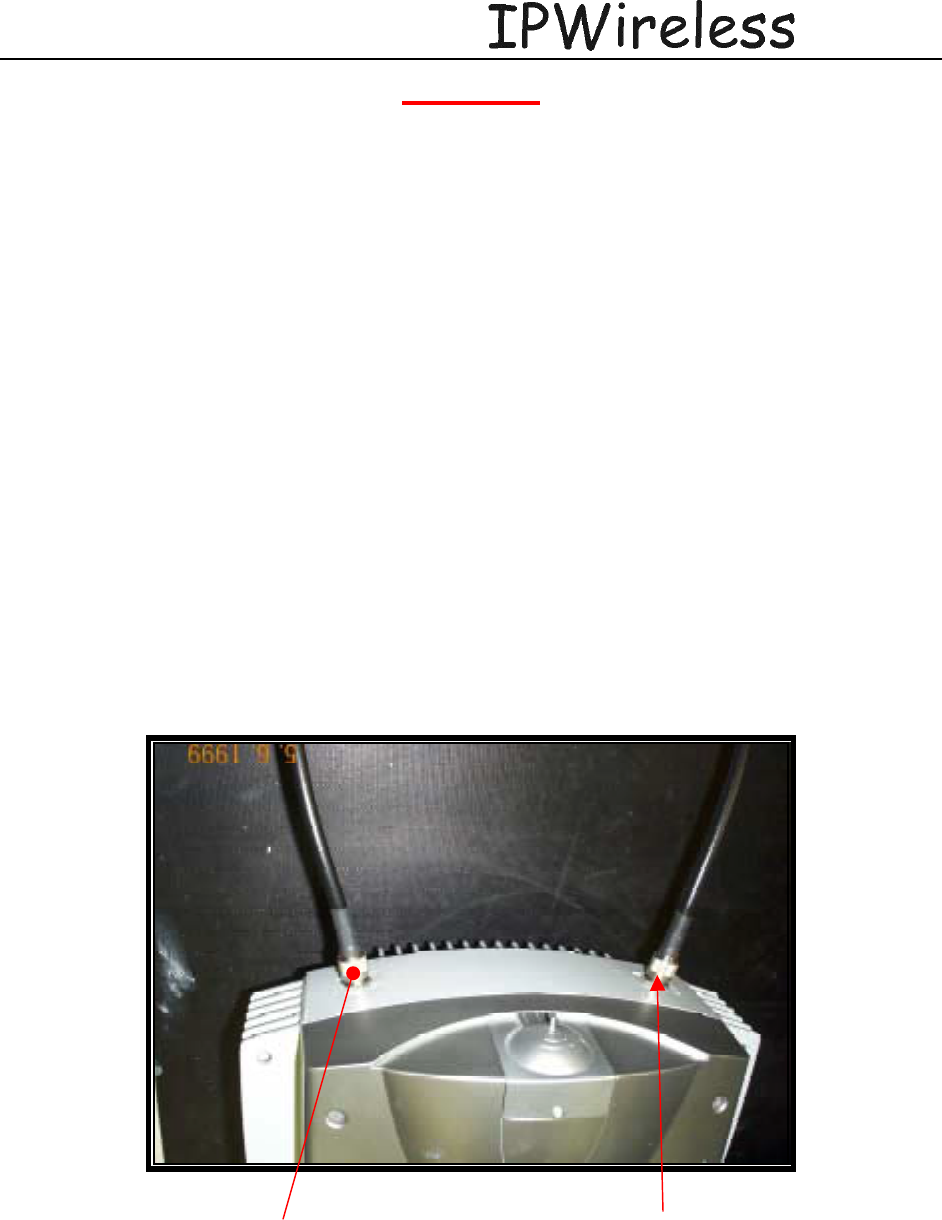
4.2 (Step 5) Antenna and Coax installation
Antenna’s and coaxial cable should be available at the site, and are part of the construction
checklist. Two antennas per Node B are required, therefore two coaxial cables per Node B
should be available.
Cables should be properly marked to indicate what antenna the coaxial cables are to be
connected to the Node B serving the sector or area.
The coaxial cables are to be terminated to a lightning arrestor and a jumper installed to the
proper length between the lightning arrestor and the Node B location.
Main Antenna Tx & Rx –
Left Hand Side Diversity Rx Antenna –
Right Hand Side
Node B Installation Guide
DRAFT
17 July, 2001 IPWireless Proprietary
IT IS ILLEGAL TO MAKE COPIES OF THIS DOCUMENT WITHOUT EXPRESS PERMISSION BY IPWIRELESS 16
4.3 (Step 7) GPS
For proper operation of the GPS receiver, the Node B must have a clear southern view of the sky.
A site survey should be done before Node B installation to verify that the Node B installation
location is suitable for GPS reception. A simple survey method is to take a handheld GPS
receiver to the site and verify that GPS lock is obtained in the location of the Node B installation.
The handheld GPS should be able to obtain a “locked” condition within 2 minutes of power-on,
and should be able to see a minimum of 4 satellites at all times. Note that when the Node B is to
be installed on or near a tower or building wall, the GPS survey should replicate this
configuration exactly.
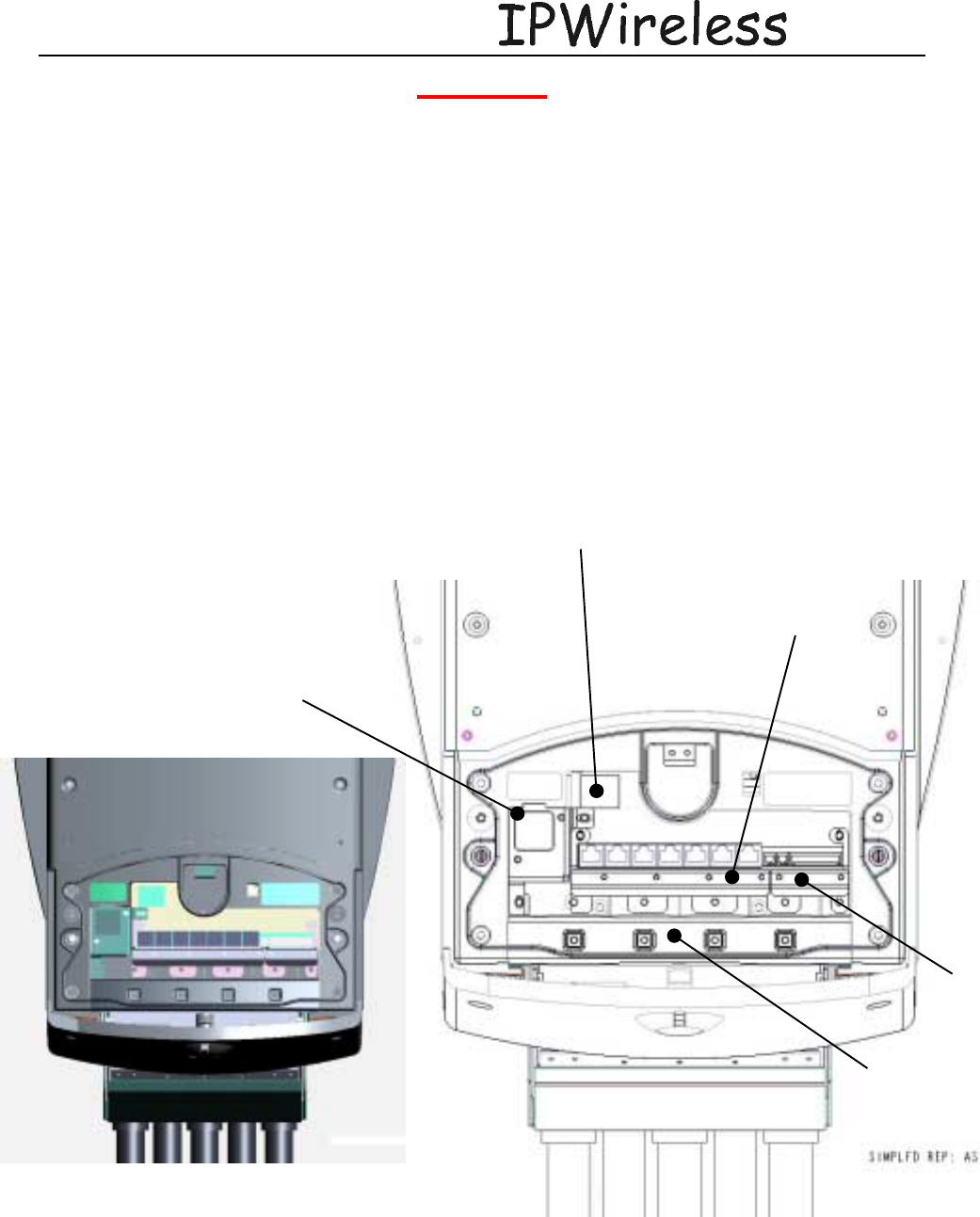
4.4 Service Cover Area
The following figures illustrate the key elements for reference in the cable interface service area
of the NodeB.
Mains Supply
Safety cover
RJ45 Cable Clamp
Alarm
Cable Clam
p
Seal Cable Clam
p
7 Segment Display

Node B Installation Guide
DRAFT
17 July, 2001 IPWireless Proprietary
IT IS ILLEGAL TO MAKE COPIES OF THIS DOCUMENT WITHOUT EXPRESS PERMISSION BY IPWIRELESS 17
4.5 (Step 9) External Alarms
If local alarms are to be utilized for a terminal block has been provided on the Node B
termination panel. The specifications for those interface requirements are below.
4.5.1 Alarm Input Specification
The alarm inputs from the Node B Patch board to the digital board shall be TTL levels and active
high.
The external alarm inputs shall be opto-isolated current loops.
The voltage and currents shall be supplied by the external source.
4.5.2 Alarm Output Specification
The alarm outputs from the digital board to the Node B Patch Board shall be TTL levels and
active high. .
The external alarm outputs shall be isolated normally-open relay contacts capable of switching at
least 100mA DC.
Node B Installation Guide
DRAFT
17 July, 2001 IPWireless Proprietary
IT IS ILLEGAL TO MAKE COPIES OF THIS DOCUMENT WITHOUT EXPRESS PERMISSION BY IPWIRELESS 18
5 (Step 10) PHYSICAL INSTALLATION OF THE NODE B
5.1 Placing the Node B into the Rack
It is assumed that the unit has been removed from the packing crate and that all materials are
checked and present, further that all the site preparation has been planned.
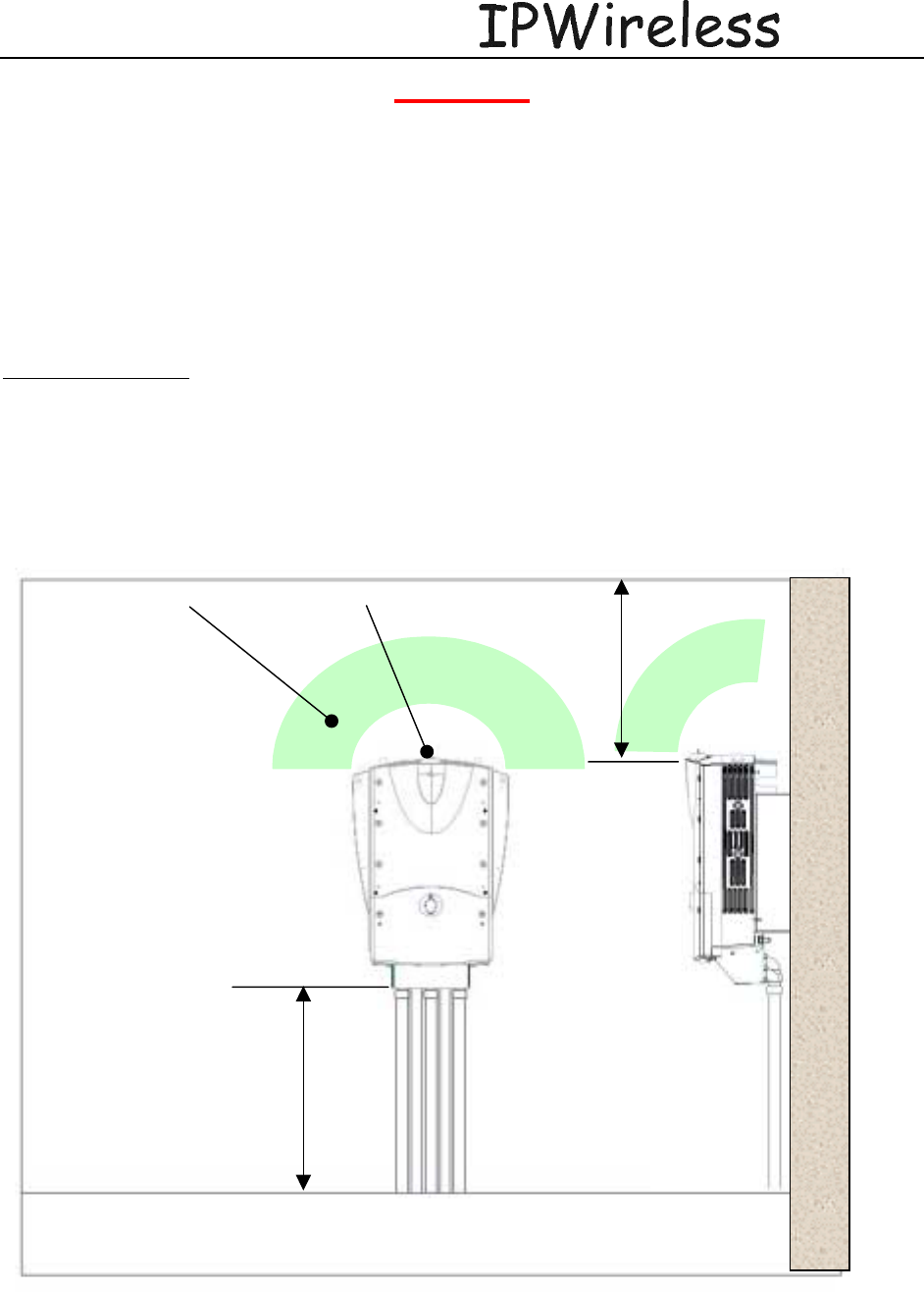
Sighting the NodeB
The first priority in sighting the NodeB is that the GPS antenna can ‘see’ the sky and therefore
the satellites. See section 4.4 for further guidance.
From a physical view point, the GPS antenna should ‘see’ at least a 90º quadrant of the ski above
the GPS antenna, see figure below.
<Detail to be added>
GPS Antenna Field
of Vision - No
Obstructions
Min 1m
Min 1m
GPS Antenna
Node B Installation Guide
DRAFT
17 July, 2001 IPWireless Proprietary
IT IS ILLEGAL TO MAKE COPIES OF THIS DOCUMENT WITHOUT EXPRESS PERMISSION BY IPWIRELESS 19
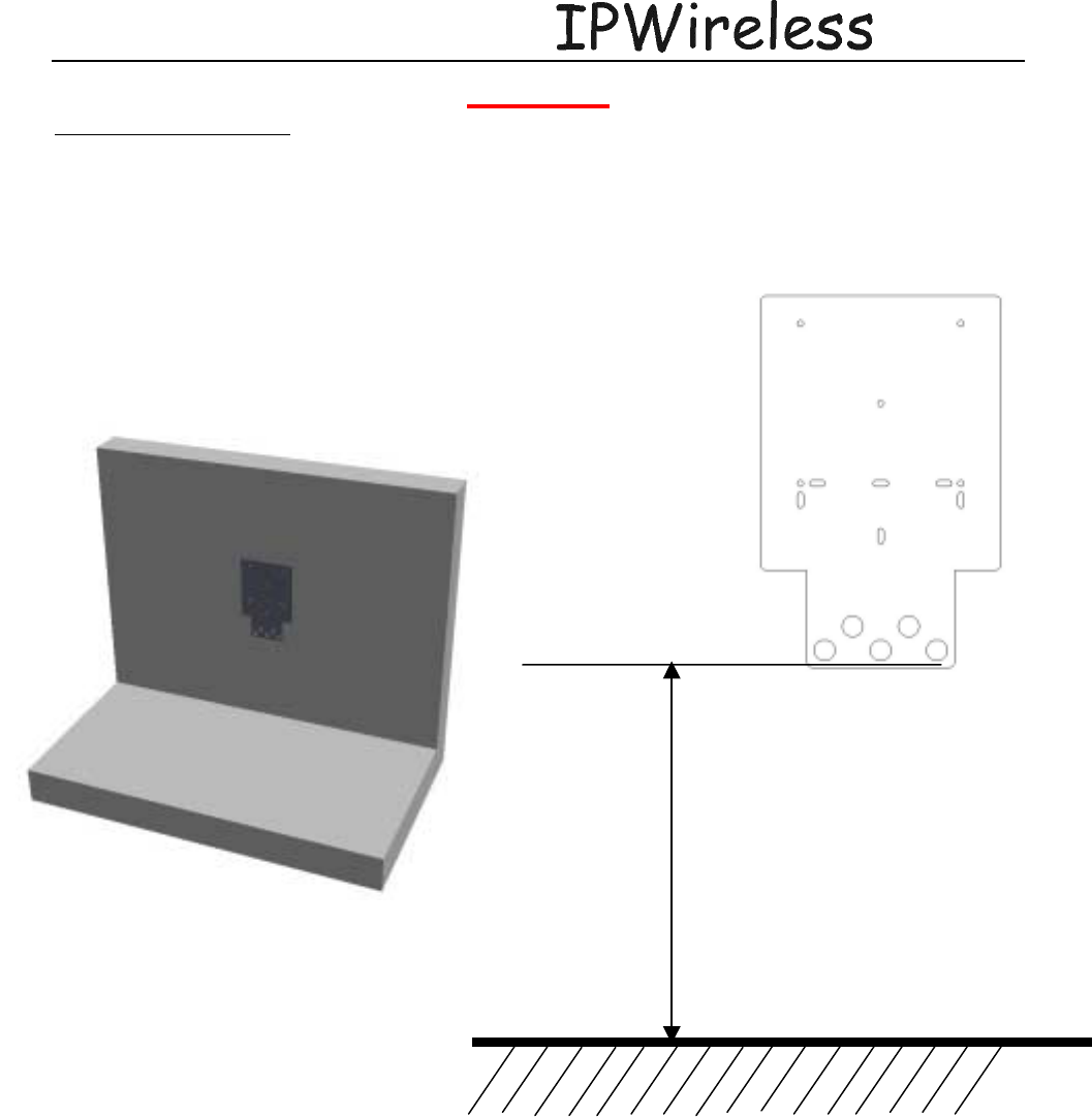
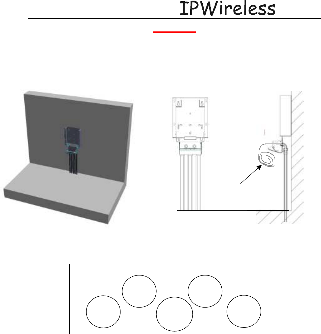
Wall Bracket Mounting
Position template and drill holes thru template at appropriate positions as marked below.
1000 mm (39.4 inches)
Node B Installation Guide
DRAFT
17 July, 2001 IPWireless Proprietary
IT IS ILLEGAL TO MAKE COPIES OF THIS DOCUMENT WITHOUT EXPRESS PERMISSION BY IPWIRELESS 20
The conduits must be fixed to the brackets prior to fixing the bracket to the wall.
Leave a sufficient loop of cables to enable them to be prep’d back to the appropriate length.
The following figure specifies the way the conduit bracket glands have been designated
signifying which cables should be fed thru which gland.
The glands and conduit should be fitted to the mount bracket prior to the NodeB being mounted
onto to the mounting bracket.
The cable should be fed thru the glands and the glands ‘sealed’ prior to the NodeB being
mounted onto to the mounting bracket. Excess cable should be fed thru.
The cables should be secured to the conduit bracket strain relief.
Looped
Cable
Power
T1 x 2
T1 x 2
or
Ethernet x1
L
N
A
Al
a
rm
s
Node B Installation Guide
DRAFT
17 July, 2001 IPWireless Proprietary
IT IS ILLEGAL TO MAKE COPIES OF THIS DOCUMENT WITHOUT EXPRESS PERMISSION BY IPWIRELESS 21
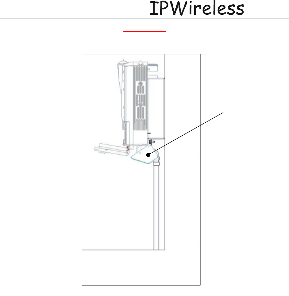
The conduit pivot bracket should be in the open position see below.
Conduit pivot
bracket open
Node B Installation Guide
DRAFT
17 July, 2001 IPWireless Proprietary
IT IS ILLEGAL TO MAKE COPIES OF THIS DOCUMENT WITHOUT EXPRESS PERMISSION BY IPWIRELESS 22
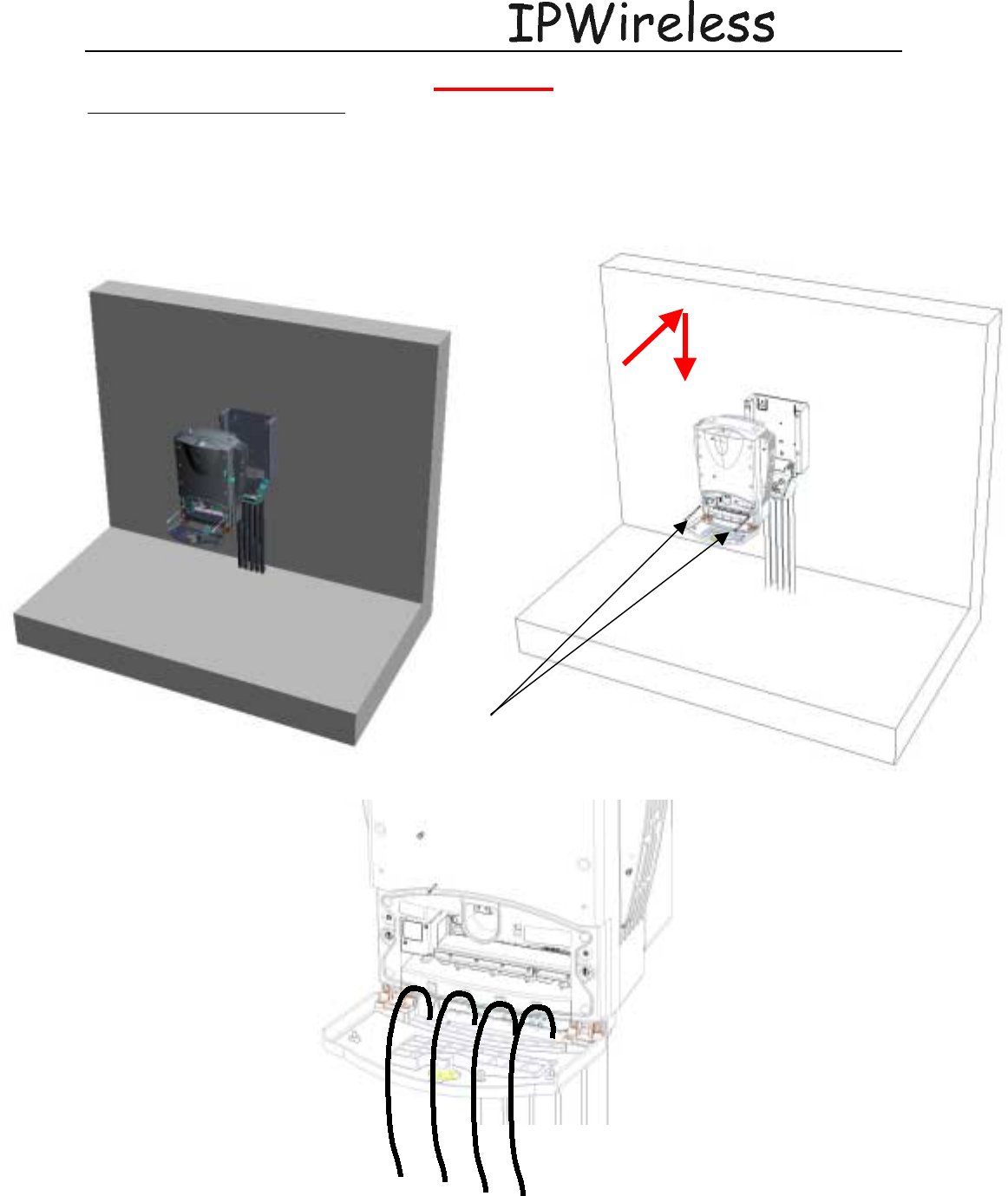
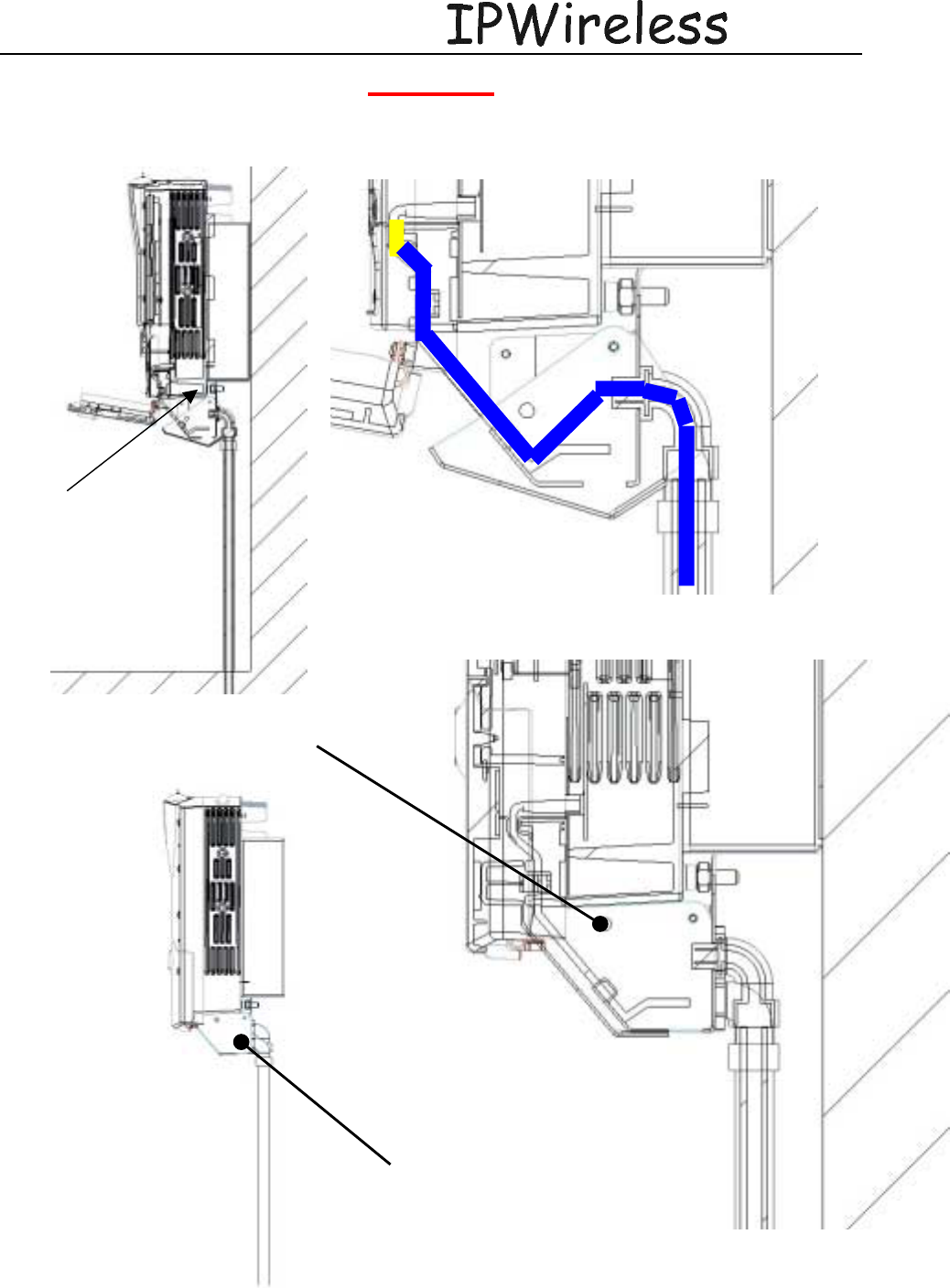
NodeB onto Mounting Bracket
o Align the top dowel pins with top holes in bracket
o Insert & drop
o Ensure all dowels are inserted, if not repeat
o Feed cables thru gap between service cover hinges
o Secure NodeB to bracket using two screws
Securing
Screws
Insert & Drop
Node B Installation Guide
DRAFT
17 July, 2001 IPWireless Proprietary
IT IS ILLEGAL TO MAKE COPIES OF THIS DOCUMENT WITHOUT EXPRESS PERMISSION BY IPWIRELESS 23
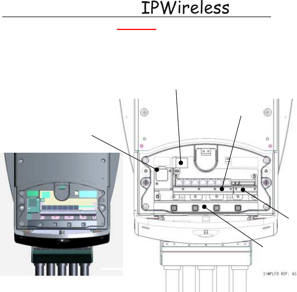
5.2 Service Area Interfaces
The following figures illustrate the key elements for reference in the cable interface service area
of the NodeB. The ground connection is at the rear of the unit see below.
Mains Supply
Safety cover
RJ45 Cable Clamp
Alarm
Cable Clam
p
Seal Cable Clam
p
7 Segment Display
Node B Installation Guide
DRAFT
17 July, 2001 IPWireless Proprietary
IT IS ILLEGAL TO MAKE COPIES OF THIS DOCUMENT WITHOUT EXPRESS PERMISSION BY IPWIRELESS 24
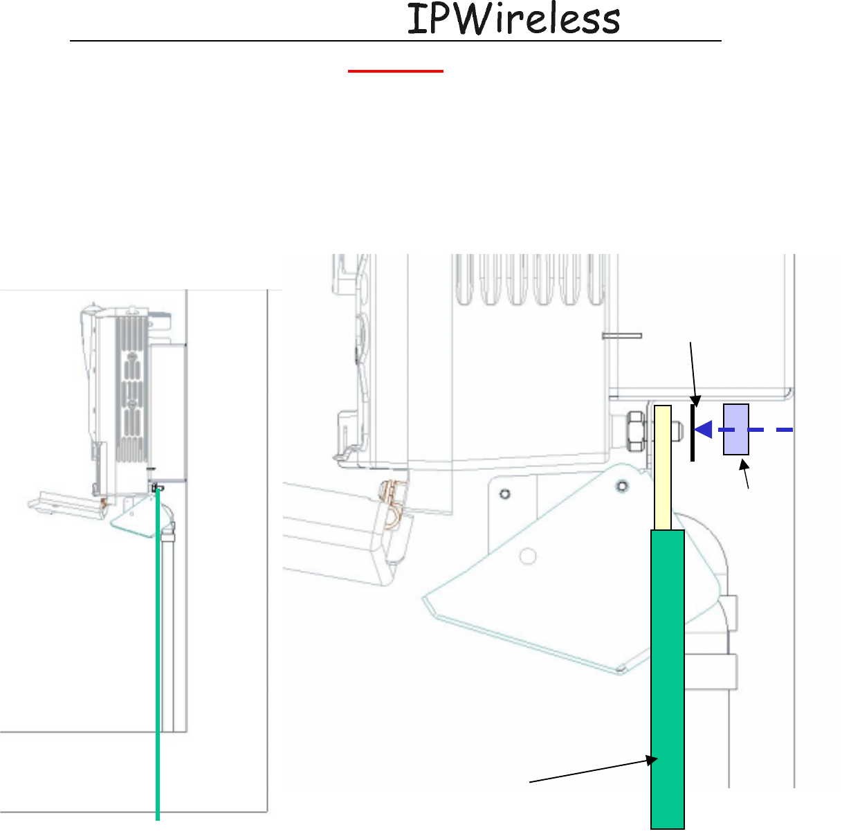
5.3 (Step 6) Grounding Installation and Inspection
Grounding materials used for the node consist of #2 AWG BCW tinned-ring solid copper wire
leading from the ground lug on the right rear section of the node to the grounding buss bar. The
grounding wire crimps on a double lug lead going from the buss bar to a grounding ring via a
Cadweld (exothermic) ground ring. A typical ground ring consists of eight foot long stainless
steel ground rods which are 5/8” diameter. Although each site will be designed for that specific
site installation.
M10 nut
M10 washer
Earth braid
Node B Installation Guide
DRAFT
17 July, 2001 IPWireless Proprietary
IT IS ILLEGAL TO MAKE COPIES OF THIS DOCUMENT WITHOUT EXPRESS PERMISSION BY IPWIRELESS 25
5.4 Cable Clamp Seal
Remove the cable clamp by loosening the 4xHex-Socket head screws, see figure below.
Seal Cable
Clamp Hex-Socket
Fixings (4off)
Seal Cable
Clamp
Removed
Node B Installation Guide
DRAFT
17 July, 2001 IPWireless Proprietary
IT IS ILLEGAL TO MAKE COPIES OF THIS DOCUMENT WITHOUT EXPRESS PERMISSION BY IPWIRELESS 26
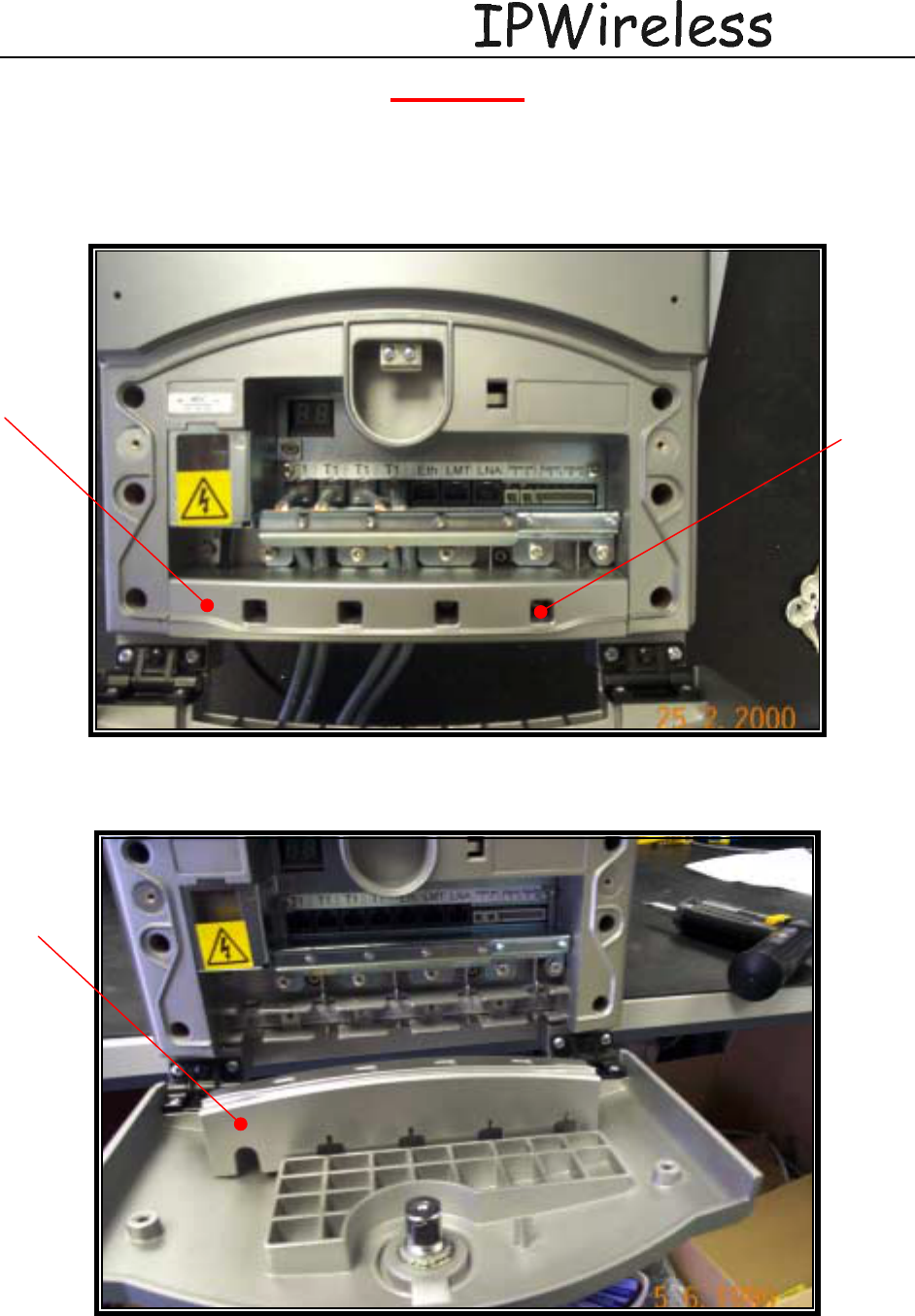
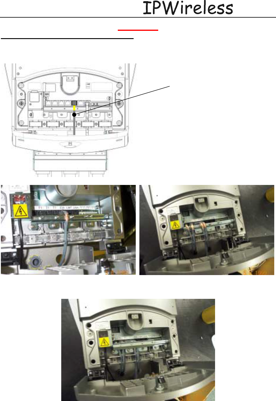
5.5 Connecting Power to the Node B
The power supply can be either universal ACDC coverter of 300W, universal input range of
90 to 240Vac with a 12Vdc output or a –48Vdc input to 12Vdc output.
• Cable preparation – Specification: terminal blocks maximum cable size 2mm2 (14AWG)
& maximum size of outer diameter 7mm.
• Remove mains protective cover (2 screws)
• Loosen strain relief Clamp Earth Clamp (2 screws)
• Insert cable into terminal block
• Secure strain relief (2 screws)
• Replace protective cover (2 screws)
Mains
Cable Clamp
Node B Installation Guide
DRAFT
17 July, 2001 IPWireless Proprietary
IT IS ILLEGAL TO MAKE COPIES OF THIS DOCUMENT WITHOUT EXPRESS PERMISSION BY IPWIRELESS 27
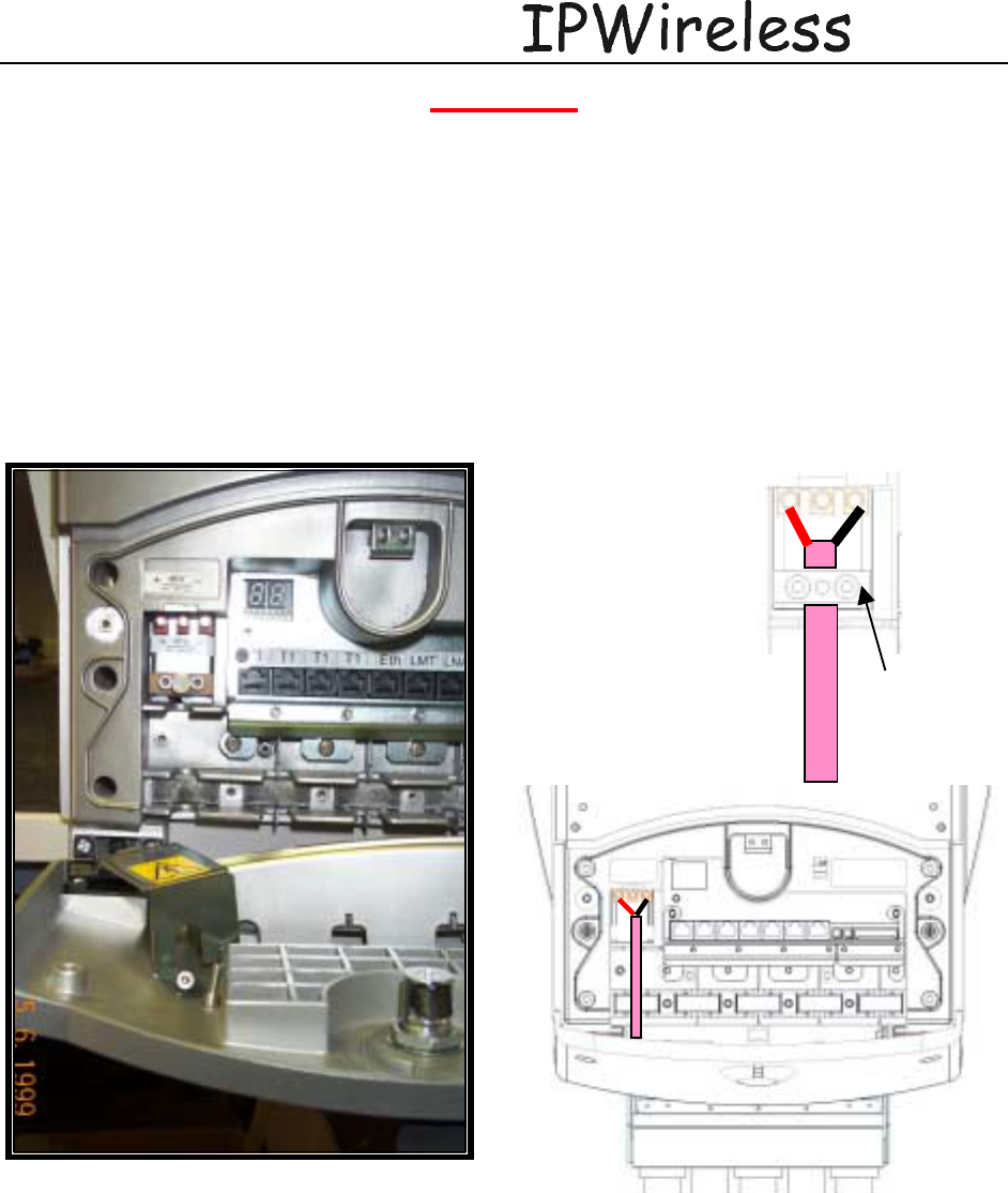
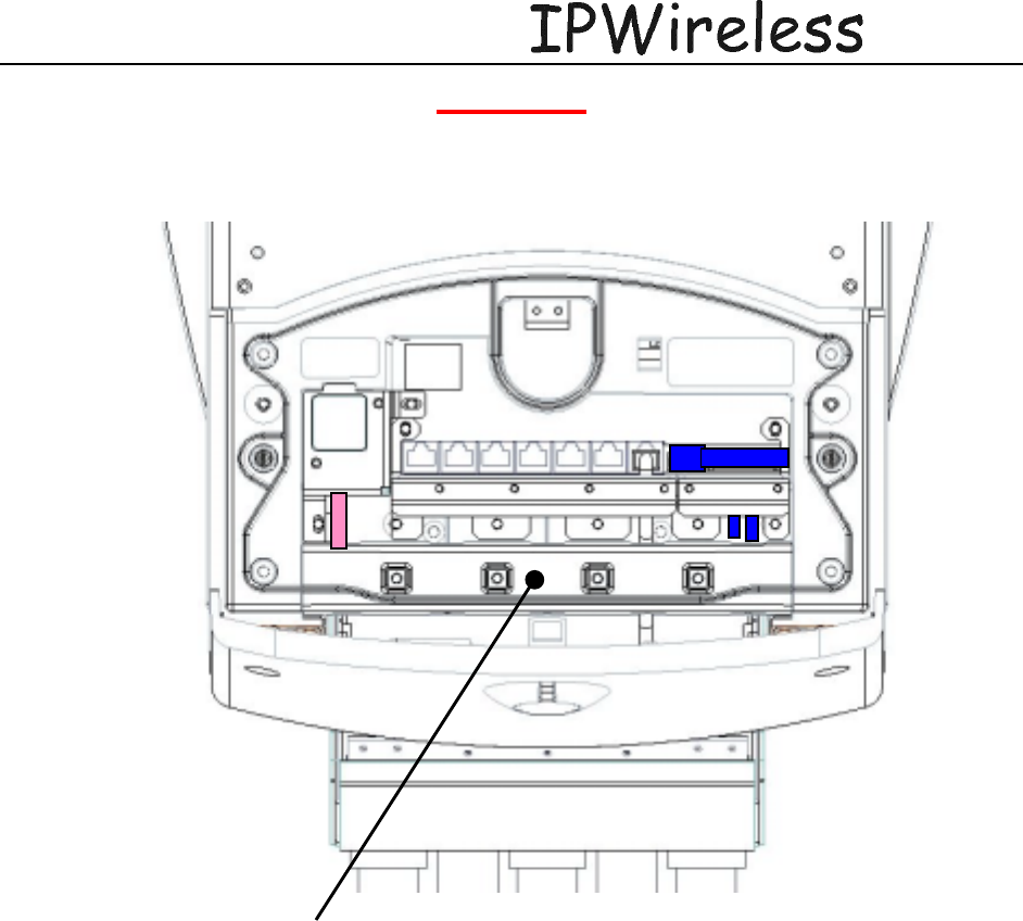
5.6 Backhaul Connections to INC
The Node B currently requires one 100 BaseT connection to a serving INC. Future
enhancements will enable (4) T1's for connection to a serving INC. The connections are labeled
and shown in the figure below.
If the Node B is in not in the same site location as the serving INC, there must be no greater than
a 5 millisecond delay on the backhaul connection. This can be provided by microwave or land
based facilities with a very high reliability rate of 99.9995%.
Terminate the Ethernet cables with RJ48 connectors and strip the wire to allow proper
connection to the earth bar. Test the continuity for the Ethernet cables with test equipment
consisting of a main and a remote unit.
The termination for these interfaces is specified within the datasheets for the interfaces. The
specification for both cables should be CAT5 - 4 pair, screened cable, recommended Alcatel
LANmark-5 F2TP or equivalent.
Power
Terminals
Protective
Cover
Backhaul
T1
(
4
)
Backhaul
100BaseT
Node B Installation Guide
DRAFT
17 July, 2001 IPWireless Proprietary
IT IS ILLEGAL TO MAKE COPIES OF THIS DOCUMENT WITHOUT EXPRESS PERMISSION BY IPWIRELESS 28
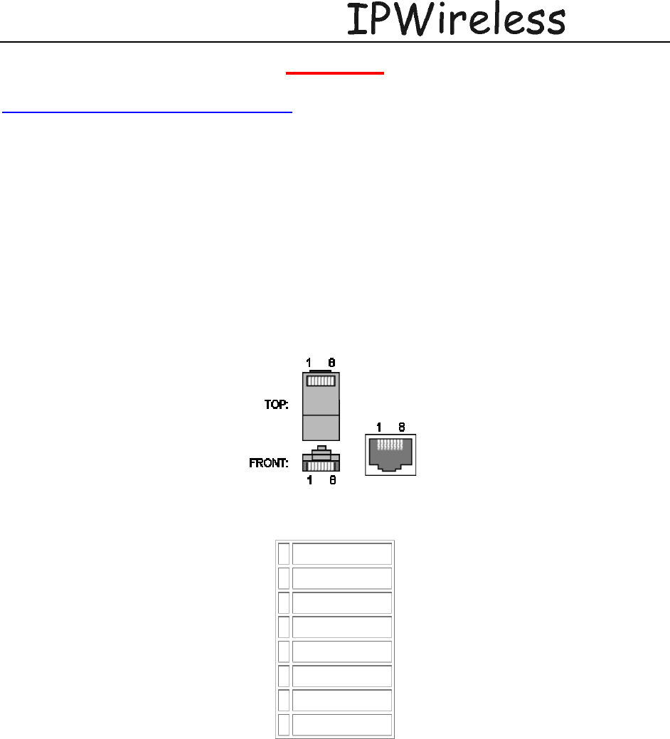
The pin-outs for the external Ethernet & T1 interfaces are given in the following tables. Source:
http://www.dcbnet.com/notes/9611t1.html
Figure 3: Ethernet Pin-outs using RJ45
1 RX + White w/Green
2 RX - Green
3 TX + White w/Orange
4 Blue
5 White w/Blue
6 TX - Orange
7 White w/Brown
8 Brown
Figure 4: T1 Pin-outs
1 Receive (ring)
2 Receive (tip)
3 Not Used
4 Transmit (ring)
5 Transmit (tip)
6 Not Used
7 Not Used
8 Not Used
Node B Installation Guide
DRAFT
17 July, 2001 IPWireless Proprietary
IT IS ILLEGAL TO MAKE COPIES OF THIS DOCUMENT WITHOUT EXPRESS PERMISSION BY IPWIRELESS 29
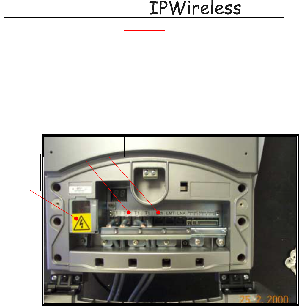
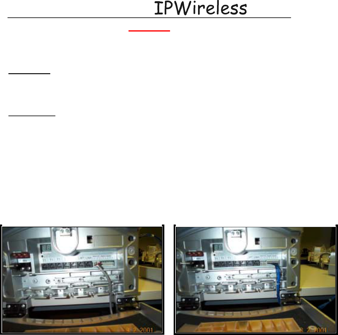
Connecting T1 or 100baseT cables to NodeB
Remove the RJ45 Cable Clamp Ground Bar 4x M3 nuts.
Replace Ground bar (4 Fixings)
Strip back outer
plastic sheath to
expose shield.
Ensure shield is
in contact with
Earth Bracket
Node B Installation Guide
DRAFT
17 July, 2001 IPWireless Proprietary
IT IS ILLEGAL TO MAKE COPIES OF THIS DOCUMENT WITHOUT EXPRESS PERMISSION BY IPWIRELESS 30
5.7 Alarm Connections
The description of the alarms is as follows
Alarm Inputs
The alarm inputs from the Node B Patch board to the digital board shall be TTL levels and active
high. The external alarm inputs shall be opto-isolated current loops. The voltage and currents
shall be supplied by the external source.
Alarm Outputs
The alarm outputs from the digital board to the Node B Patch Board shall be TTL levels and
active high. The external alarm outputs shall be isolated normally-open relay contacts capable of
switching at least 100mA DC.
The connectors are 12way (alarm inputs) and 2ways for the alarm outputs, 2.5mm pitch header
that mate with the supplied cable mount – tension clamp. The cables should be stripped 5-6mm
and inserted into the connector prior to mating with the NodeB.
The signals are paired starting from the right, pin1 is the right-hand-side on each connector.
Figure 4 : Alarm Outputs (2x2) Figure 4 : Alarm Inputs
Node B Installation Guide
DRAFT
17 July, 2001 IPWireless Proprietary
IT IS ILLEGAL TO MAKE COPIES OF THIS DOCUMENT WITHOUT EXPRESS PERMISSION BY IPWIRELESS 31
5.8 Replacement of the Seal cable clamp
Replace Seal Cable Clamp &
secure with 4 x M4 screws
Node B Installation Guide
DRAFT
17 July, 2001 IPWireless Proprietary
IT IS ILLEGAL TO MAKE COPIES OF THIS DOCUMENT WITHOUT EXPRESS PERMISSION BY IPWIRELESS 32
5.9 Conduit Pivot Bracket Securing
2 x M4 fixings
Torqued 5Nm
Conduit Pivot
pivot bracket
open
Node B Installation Guide
DRAFT
17 July, 2001 IPWireless Proprietary
IT IS ILLEGAL TO MAKE COPIES OF THIS DOCUMENT WITHOUT EXPRESS PERMISSION BY IPWIRELESS 33
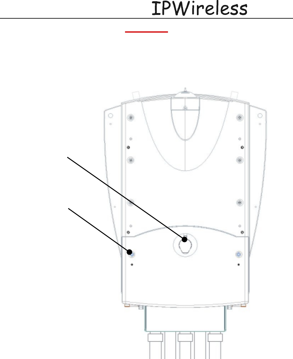
5.10 Closing the Door and securing the NodeB
Close door and firmly press in centre point at lock ensure latch ‘clicks’ into place. Secure service
cover with 2 screws.
2x M4 Socket Hex
Bolts
Press firmly to
ensure lock latch

Node B Installation Guide
DRAFT
17 July, 2001 IPWireless Proprietary
IT IS ILLEGAL TO MAKE COPIES OF THIS DOCUMENT WITHOUT EXPRESS PERMISSION BY IPWIRELESS 34
5.11 GPS
5.5.1 GPS Operation
The Node B has an integral GPS antenna and receiver, as shown in figure above. The GPS
timing signal is used by the Node B for the TDD frame timing, so that all Node B’s in a network
are synchronized. The GPS signal is also used by the master oscillator for a frequency reference.
The Node B can operate for several hours after a loss of GPS timing but a gradual drift of the
frame timing will result in system interference and a loss of handoff capability.
The GPS receiver is automatically enabled when the Node B is powered and there are no
adjustments or settings to be made by the user.
After installation of the Node B, verify proper operation of the GPS receiver by connecting the
Local Maintenance Terminal (LMT) to the LMT port and accessing typing “gpsstats”.
5.5.3 GPS Repeater Installations
A GPS repeater functions as a reradiating repeater to provide a GPS signal in areas that do not
have a clear view of the sky. The repeater consists of an active antenna, a repeater block, a
passive antenna, connecting cables and a +12VDC supply
The location of the active antenna should be chosen so that the antenna has a clear view of the
sky. A suitable location can be verified before installation by checking for GPS lock with a
handheld GPS unit. The repeater block and passive antenna are installed in the coverage area
(Node B location). The +12VDC supply can be provided by a wall transformer that is connected
to a UPS.
After installation and power-on, verify that the handheld GPS unit is able to obtain GPS lock
inside the Node B installation area. If not, make adjustments to the antenna locations as required
until the handheld GPS receiver can obtain lock. After the Node B is installed, verify that the
Node B GPS receiver is able to obtain and keep GPS lock condition.

Node B Installation Guide
DRAFT
17 July, 2001 IPWireless Proprietary
IT IS ILLEGAL TO MAKE COPIES OF THIS DOCUMENT WITHOUT EXPRESS PERMISSION BY IPWIRELESS 35
6 (Step 11) Power up and Initial Setup of Node B
8 (Step 12) SOFTWARE INSTALLATION
Registration
IPWireless Network Controller software
9 (Step 13) On Air final check
10 Operation & Maintenance
10.1 Maintenance
Node B is designed for an in-service lifetime of 10 years.
There are no field repairable items within the NodeB.

Node B Installation Guide
DRAFT
17 July, 2001 IPWireless Proprietary
IT IS ILLEGAL TO MAKE COPIES OF THIS DOCUMENT WITHOUT EXPRESS PERMISSION BY IPWIRELESS 38
APPENDIX A – CONTACT INFORMATION
Colorado California Europe
IPWireless
1707 Cole Blvd.
Golden, CO 80401
IPWireless
1250 Bayhill Drive
Suite 113
San Bruno, CA 94066
IPWireless
4 Lansdowne Court
Bumpers Way
Chippenham
SN14 6RZ
Fax# (303) 274-6252 Fax: +1-650 794-2668

Node B Installation Guide
DRAFT
17 July, 2001 IPWireless Proprietary
IT IS ILLEGAL TO MAKE COPIES OF THIS DOCUMENT WITHOUT EXPRESS PERMISSION BY IPWIRELESS 39
APPENDIX B – BACKHAUL SPECIFICATIONS
Node B Installation Guide
DRAFT
17 July, 2001 IPWireless Proprietary
IT IS ILLEGAL TO MAKE COPIES OF THIS DOCUMENT WITHOUT EXPRESS PERMISSION BY IPWIRELESS 41
APPENDIX D – Node B SPECIFICATIONS
Size 16” H x 12” W x 5” D
Weight 42 Pounds
RF Power output +34 dBm composite (maximum)
Receive Sensitivity -110 dBm/6 MHz channel
Antenna connector type N F X 3 (Tx, Tx/Rx, GPS receiver)
Maximum antenna line loss 2 dB suggested
Power consumption 300 Watts maximum
Voltage requirement -48 VDC or 110 VAC (Optioned at time of order)
Head Disipation 184 Watts
Backhaul facility throughput 6 Mbps downlink, 3 Mbps uplink
Backhaul facility type 4 X T1, 100BT Ethernet
LMT interface 10/100BT Ethernet
Frequency Range 2500 MHz – 2686 MHz
Bandwidth 12 MHz
Air Interface UTRAN TD-CDMA
Duplex method Time division
Chipping Rate 7.68 Mcps
Spreading Codes OVSF
Maximum Path loss 150 Db
Error Correction variable punctured Turbo coding
Spreading factor variable - 4, 8 and 16
Modulation QPSK

Node B Installation Guide
DRAFT
17 July, 2001 IPWireless Proprietary
IT IS ILLEGAL TO MAKE COPIES OF THIS DOCUMENT WITHOUT EXPRESS PERMISSION BY IPWIRELESS 42
Glossary
ADC Analog to Digital Converter
BTS Base Transceiver Station
DAC Digital to Analog Converter
Downlink From Network to the User Equipment
DSCH Downlink Shared Channel
ETSI European Telecommunications Standardization Institute
FIFO First-In First-Out (buffer)
FPGA Field Programmable Gate Array
HTTP Hyper-Text Transfer Protocol
INC Integrated Node Controller
IP Internet Protocol
ISP Internet Service Provider
ITFS Instructional Television Fixed Service
IUB Iub interface – Node B to INC interface
LMT Local Maintenance Terminal
LNA Low Noise Amplifier
MCP Multimedia Communications Port
MAC Media Access Control
Mcps Mega Chips per Second
MMDS Multichannel Multipoint Distribution Service
MSPS Mega Samples Per Second
MTU Maximum Transmission Unit
Node B A UMTS Radio Base Station
PDU Protocol Data Unit
PLL Phase Locked Loop
QPSK Quadrature Phase Shift Keying
RAM Random Access Memory
RLC Radio Link Control
RRC Root Raised Cosine
SDU Service Data Unit
SRAM Static RAM
T1 1536kbps pipe
TD-CDMA Time Division Code Division Multiple Access
TDD Time Division Duplex
UART Univeral Asynchronous Receiver Transmitter
UE User Equipment
UMTS Universal Mobile Telecommunications System
Uplink From User Equipment to the Network
USB Universal Serial Bus
USCH Uplink Shared Channel
UTRAN UMTS Terrestrial Radio Access Network
VCXO Voltage Controlled Crystal Oscillator