General Dynamics Broand NODEBHZ1 Wireless Broadband Base Station User Manual NodeB V2 Installation Guide 01

General Dynamics Broadband, Inc. Wireless Broadband Base Station NodeB V2 Installation Guide 01

Contents

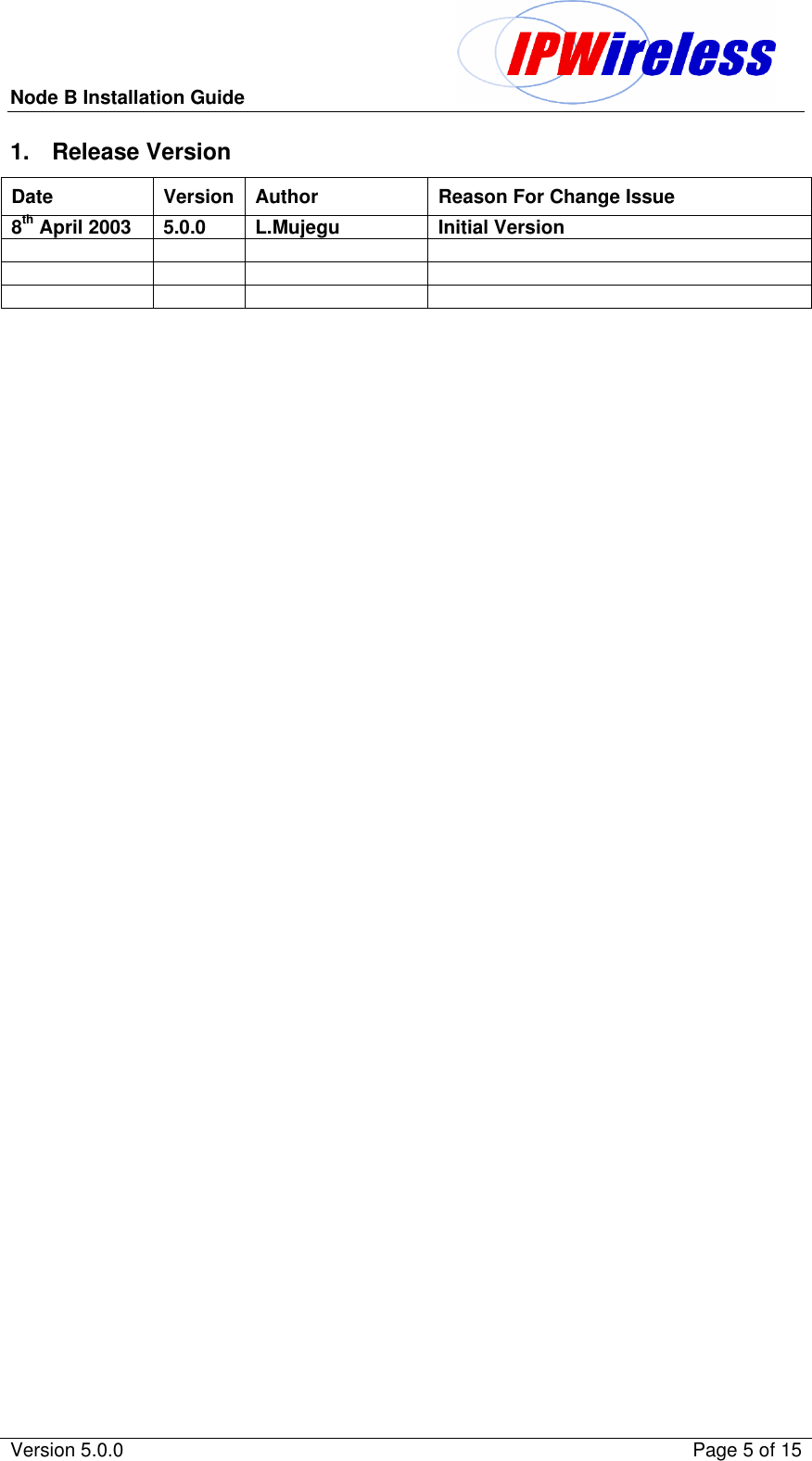
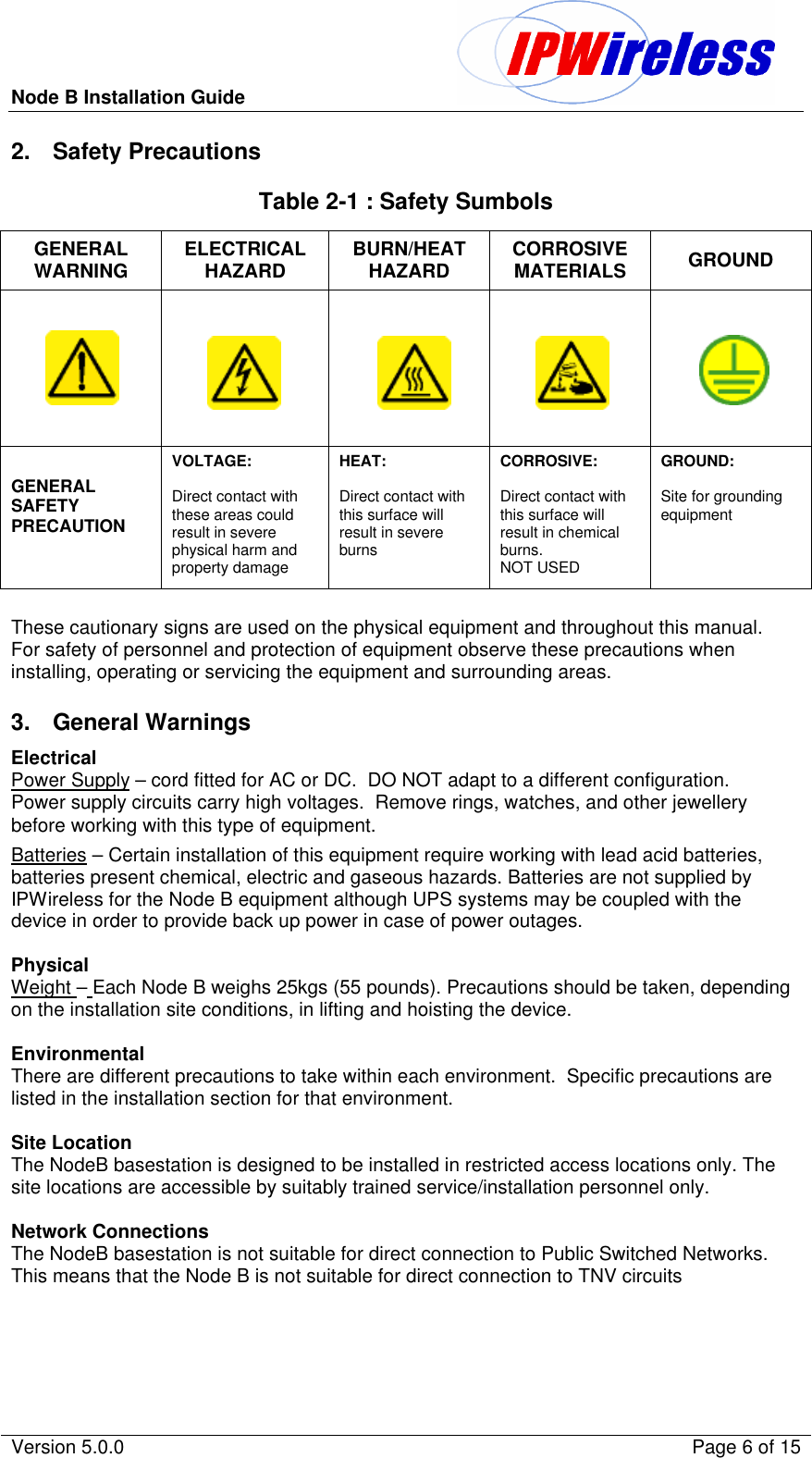
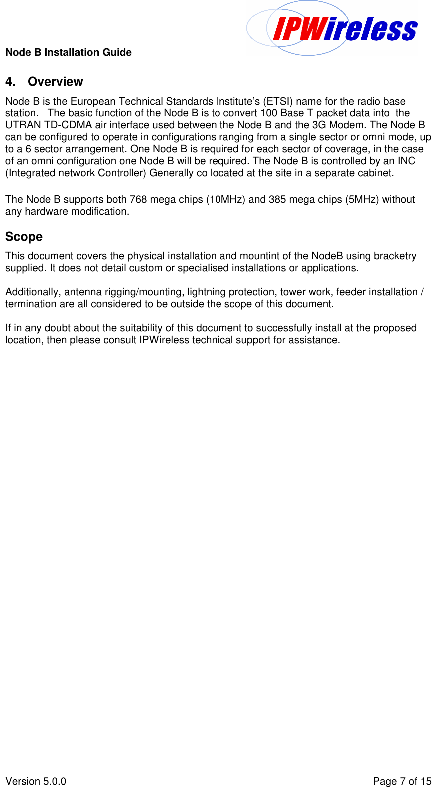
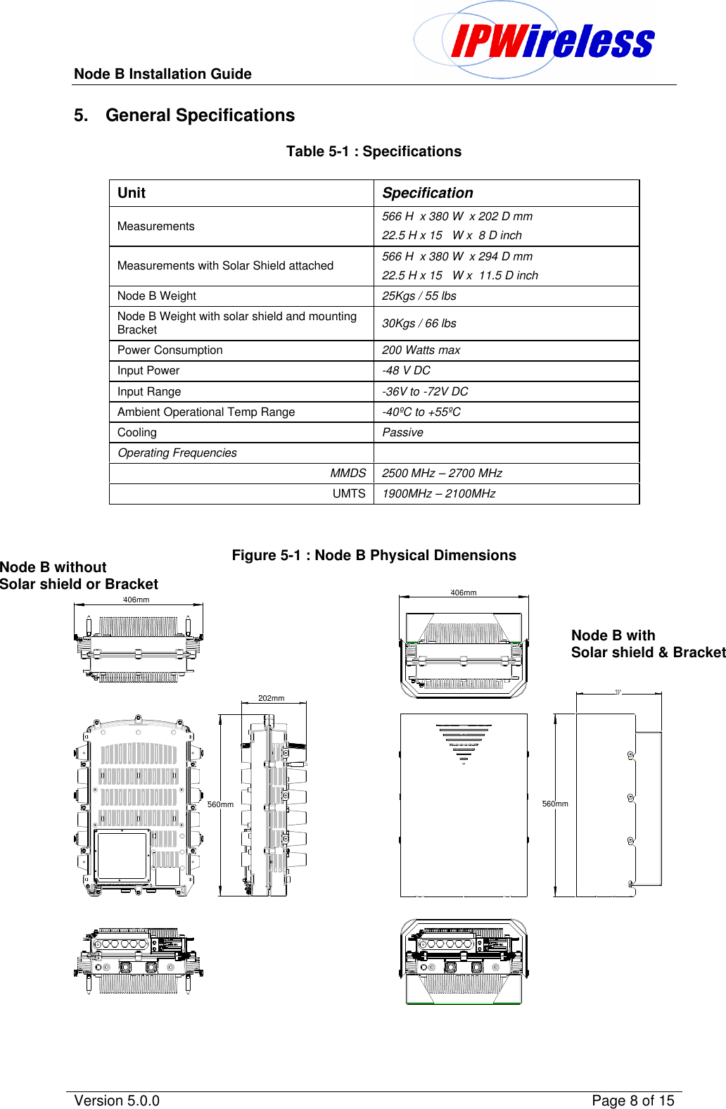
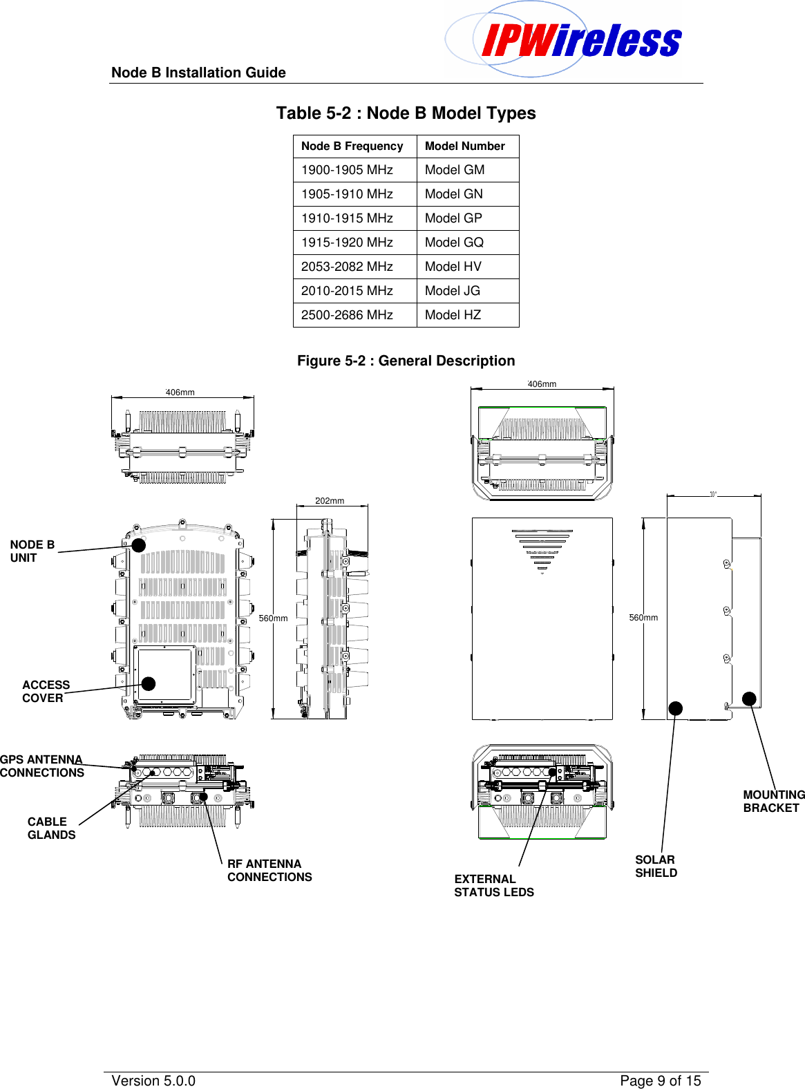
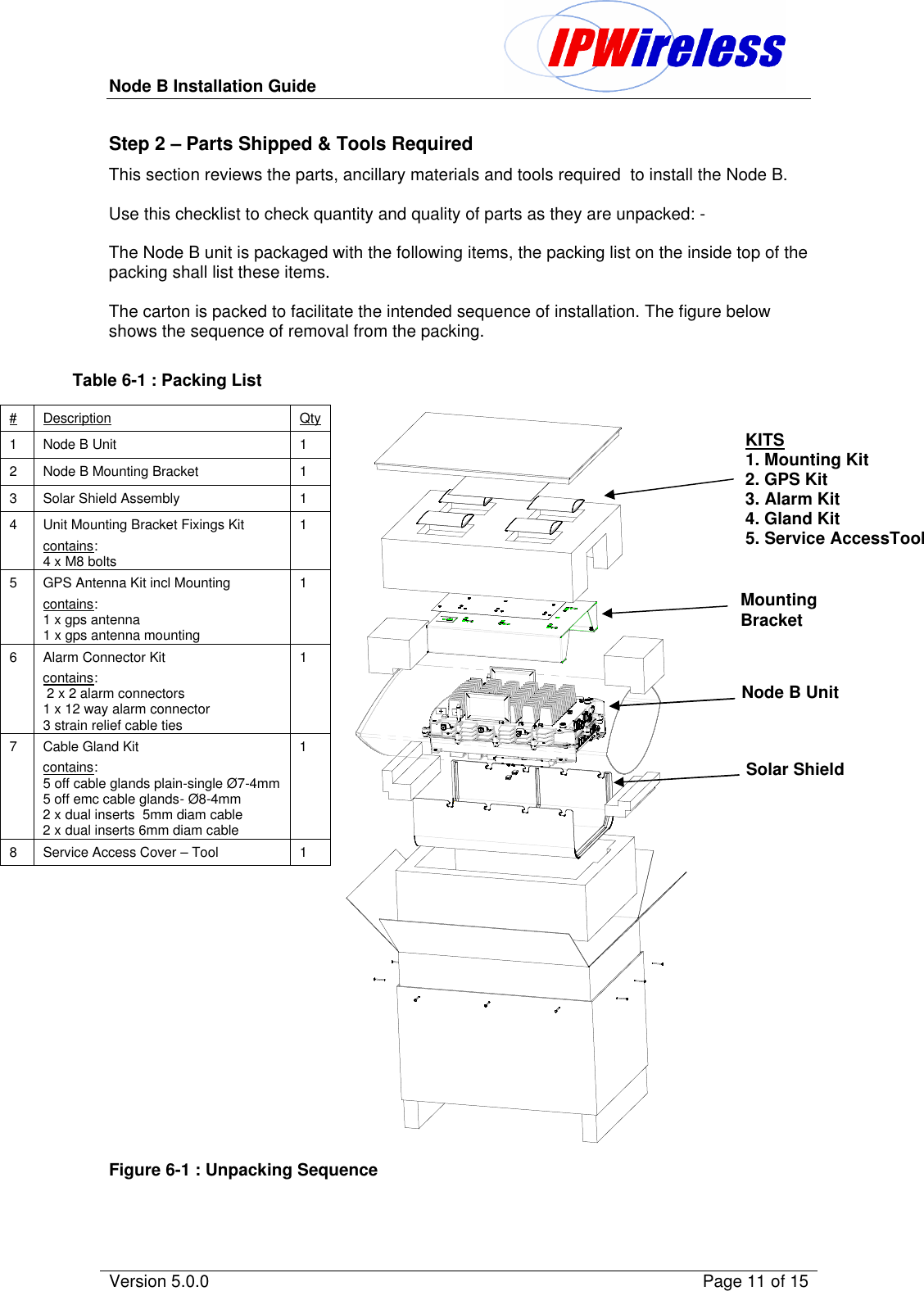
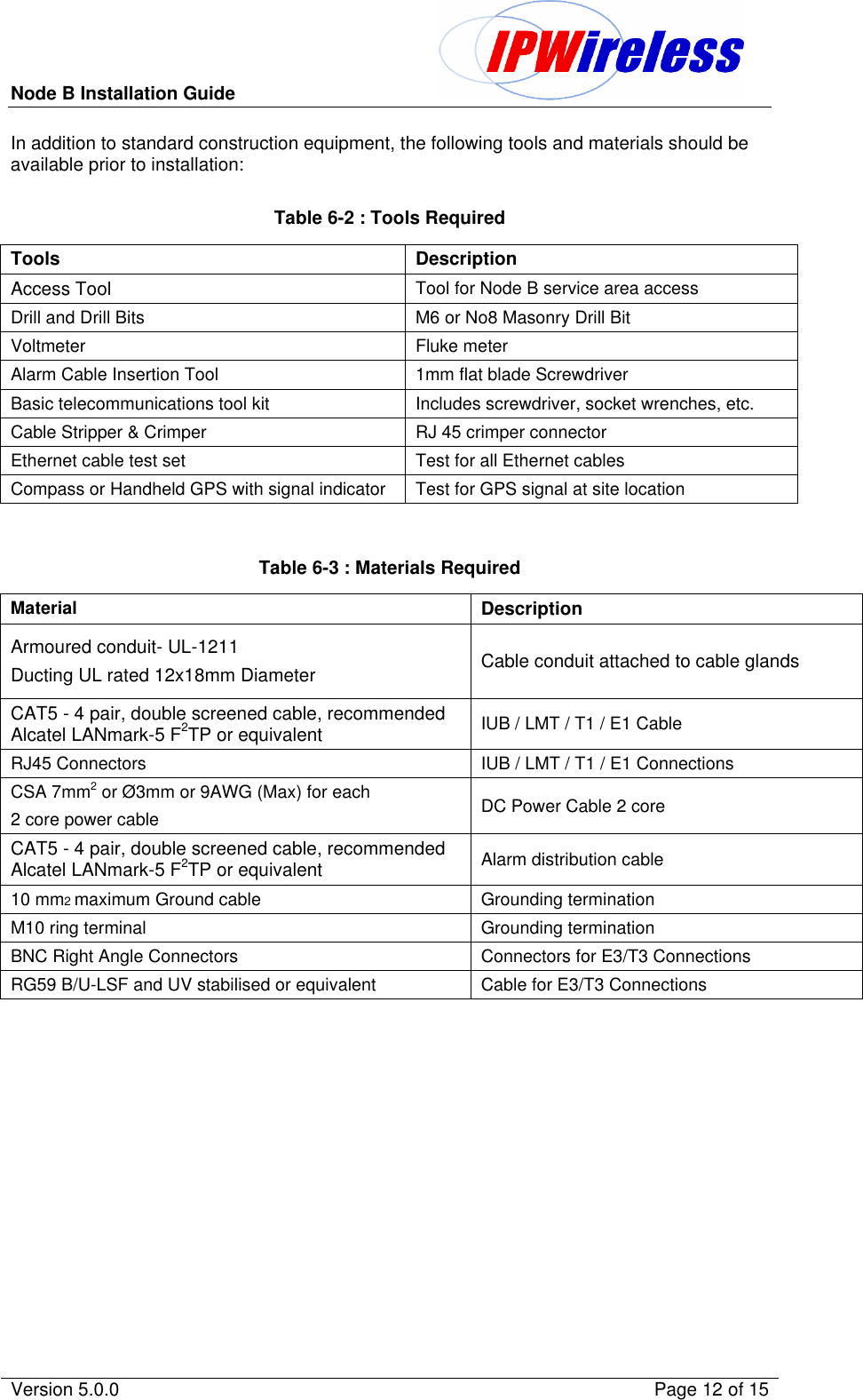
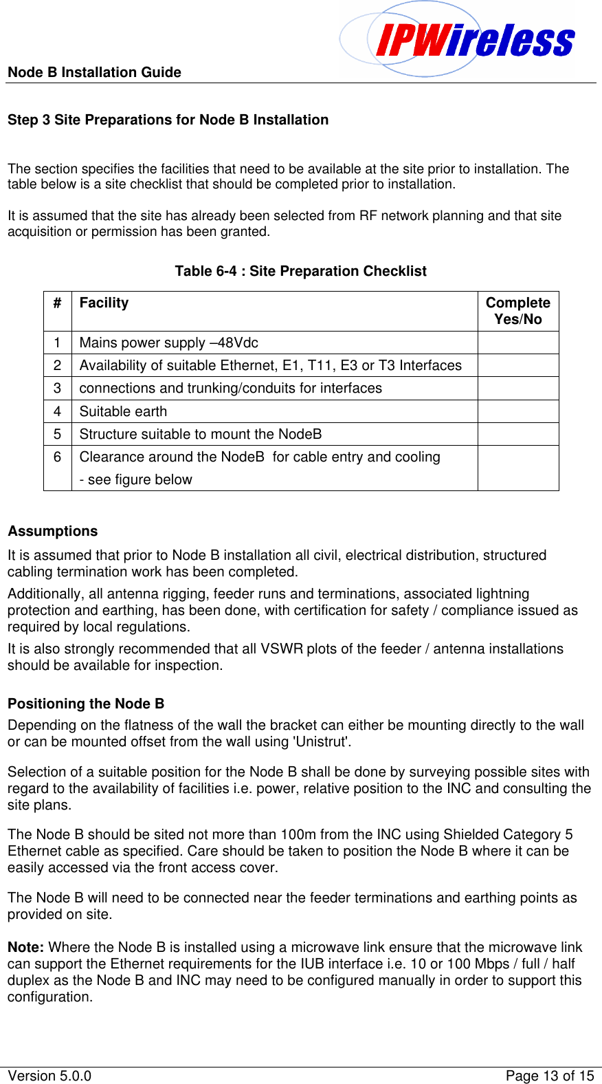
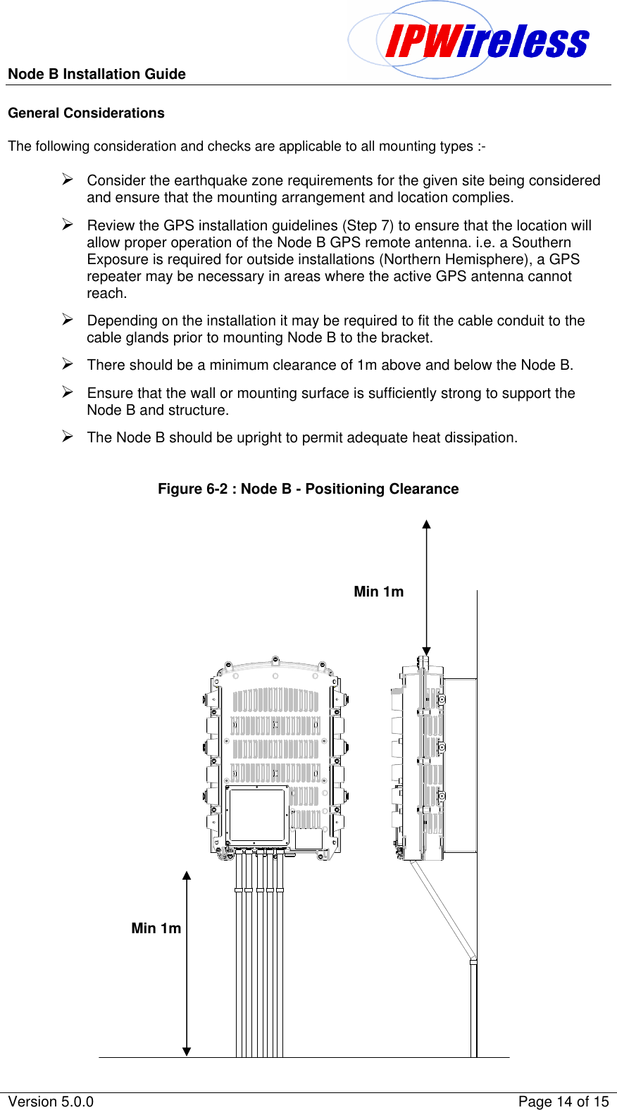
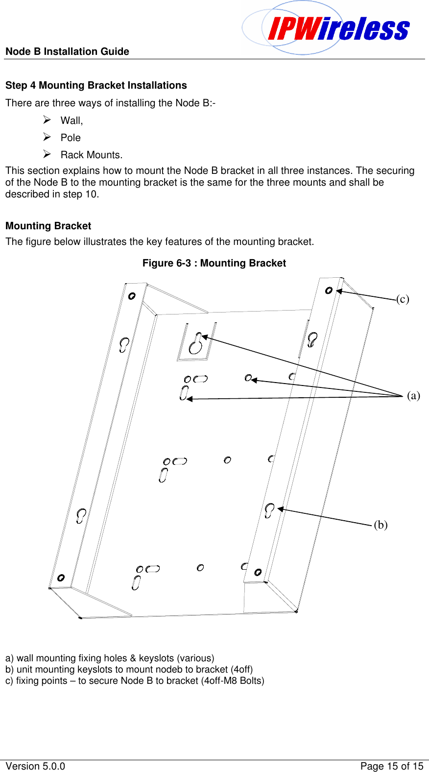
Installation Guide 1

Node B Installation Guide                                               Version 5.0.0    Page 1 of 15         Node B V2   Installation Guide
Node B Installation Guide                                               Version 5.0.0    Page 2 of 15                              Information in this document and the products described are subject to change without notice. 2000-2003 IPWireless, Inc. All rights reserved. Reproduction, alteration, or distribution in any manner whatsover without the written permission of IPWireless Inc, is strictly  forbidden. Trademarks used in this text: the IPWireless  logo, icon and IPWireless Broadband Modeem are trademarks of IPWireless, Inc.; Microsoft, Windows, and Windows NT are registered trademarks of Microsoft Corporation. Other trademarks and trade names may be used in this document to refer to either the entities claiming the marks and names or their products, IPWireless, Inc., disclaims any proprietary interest in trademarks and trade names other than its own. February 2003   Part No. IPW-0463
Node B Installation Guide                                               Version 5.0.0    Page 3 of 15  Table of Contents 1. Release Version ..............................................................................................5 2. Safety Precautions..........................................................................................6 3. General Warnings ...........................................................................................6 4. Overview..........................................................................................................7 5. General Specifications....................................................................................8 6. Installation.....................................................................................................10 Step 1- Pre-Installation.....................................................................................10 Step 2 – Parts Shipped & Tools Required.......................................................11 Step 3 Site Preparations for Node B Installation............................................13 Step 4 Mounting Bracket Installations ............................................................15 Step 5 Conduit Installation & Cabling ................... Error! Bookmark not defined. Step 6 Node B Installation onto Mounting Bracket ............ Error! Bookmark not defined. Step 7 Ground Installation ..................................... Error! Bookmark not defined. Step 8 Service Cover Access................................. Error! Bookmark not defined. Step 9 DC Power Connection................................. Error! Bookmark not defined. Step 10 Backhaul Connections (Iub) to INC.......... Error! Bookmark not defined. Step 12 Antenna Cabling - Installation.................. Error! Bookmark not defined. Step 13 Alarm Connections ................................... Error! Bookmark not defined. Step 14 GPS Installation & Operation ................... Error! Bookmark not defined. Step 15 Solar Shield Installation............................ Error! Bookmark not defined. 7. APPENDIX............................................................ Error! Bookmark not defined. Appendix A - Installation Check Card ................... Error! Bookmark not defined. Appendix B - Glossary ........................................... Error! Bookmark not defined.
Node B Installation Guide                                               Version 5.0.0    Page 4 of 15  Table of Tables Table 2-1 : Safety Sumbols......................................................................................................6 Table 5-1 : Specifications.........................................................................................................8 Table 5-2 : Node B Model Types .............................................................................................9 Table 6-1 : Packing List..........................................................................................................11 Table 6-2 : Tools Required.....................................................................................................12 Table 6-3 : Materials Required...............................................................................................12 Table 6-4 : Site Preparation Checklist ...................................................................................13 Table 6-5 : T1/E1 Pin-outs .......................................................Error! Bookmark not defined.  Table of Figures Figure 5-1 : Node B Physical Dimensions ...............................................................................8 Figure 5-2 : General Description..............................................................................................9 Figure 6-1 : Unpacking Sequence ......................................................................................11 Figure 6-2 : Node B - Positioning Clearance .........................................................................14 Figure 6-3 : Mounting Bracket................................................................................................15 Figure 6-4: Drill template.......................................................Error! Bookmark not defined. Figure 6-5 : Bracket Fixing to Wall - Wall.................................Error! Bookmark not defined. Figure 6-6: Node B Securing to Uneven Wall..........................Error! Bookmark not defined. Figure 6-7 : Pole Mounting using Unistrut systems .................Error! Bookmark not defined. Figure 6-8 : Node B - Rack Mounted .......................................Error! Bookmark not defined. Figure 6-9: Flexible Conduit.....................................................Error! Bookmark not defined. Figure 6-10: Node B onto Mounting Bracket............................Error! Bookmark not defined. Figure 6-11 : Earth Connection................................................Error! Bookmark not defined. Figure 6-12 : Service Access...................................................Error! Bookmark not defined. Figure 6-13 : Service Area Description....................................Error! Bookmark not defined. Figure 6-14 : Power Connections ............................................Error! Bookmark not defined. Figure 6-15 : Backhaul Connections........................................Error! Bookmark not defined. Figure 6-16 : Ethernet Pin-outs using RJ45.............................Error! Bookmark not defined. Figure 6-17 : Ethernet Pin-outs using RJ45.............................Error! Bookmark not defined. Figure 6-18 : Antenna Connections .....................................Error! Bookmark not defined. Figure 6-19 : Alarm Outputs & Inputs ......................................Error! Bookmark not defined. Figure 6-20 : GPS Antenna......................................................Error! Bookmark not defined. Figure 6-21 : Solar Shield Fitting .............................................Error! Bookmark not defined. Figure 6-22 : Solar Shield Securing.........................................Error! Bookmark not defined. Figure 6-23 : Solar Shield Hooked on Node B.........................Error! Bookmark not defined.
Node B Installation Guide                                               Version 5.0.0    Page 5 of 15  1. Release Version Date Version Author Reason For Change Issue 8th April 2003 5.0.0 L.Mujegu Initial Version
Node B Installation Guide                                               Version 5.0.0    Page 6 of 15  2. Safety Precautions Table 2-1 : Safety Sumbols GENERAL WARNING ELECTRICAL HAZARD BURN/HEAT HAZARD CORROSIVE MATERIALS GROUND          GENERAL SAFETY PRECAUTION  VOLTAGE:  Direct contact with these areas could result in severe physical harm and property damage HEAT:   Direct contact with this surface will result in severe burns CORROSIVE:  Direct contact with this surface will result in chemical burns. NOT USED GROUND:  Site for grounding equipment  These cautionary signs are used on the physical equipment and throughout this manual.  For safety of personnel and protection of equipment observe these precautions when installing, operating or servicing the equipment and surrounding areas.  3. General Warnings Electrical Power Supply – cord fitted for AC or DC.  DO NOT adapt to a different configuration. Power supply circuits carry high voltages.  Remove rings, watches, and other jewellery before working with this type of equipment. Batteries – Certain installation of this equipment require working with lead acid batteries, batteries present chemical, electric and gaseous hazards. Batteries are not supplied by IPWireless for the Node B equipment although UPS systems may be coupled with the device in order to provide back up power in case of power outages.  Physical Weight – Each Node B weighs 25kgs (55 pounds). Precautions should be taken, depending on the installation site conditions, in lifting and hoisting the device.  Environmental There are different precautions to take within each environment.  Specific precautions are listed in the installation section for that environment.  Site Location The NodeB basestation is designed to be installed in restricted access locations only. The site locations are accessible by suitably trained service/installation personnel only.  Network Connections The NodeB basestation is not suitable for direct connection to Public Switched Networks. This means that the Node B is not suitable for direct connection to TNV circuits
Node B Installation Guide                                               Version 5.0.0    Page 7 of 15  4. Overview Node B is the European Technical Standards Institute’s (ETSI) name for the radio base station.   The basic function of the Node B is to convert 100 Base T packet data into  the UTRAN TD-CDMA air interface used between the Node B and the 3G Modem. The Node B can be configured to operate in configurations ranging from a single sector or omni mode, up to a 6 sector arrangement. One Node B is required for each sector of coverage, in the case of an omni configuration one Node B will be required. The Node B is controlled by an INC (Integrated network Controller) Generally co located at the site in a separate cabinet.  The Node B supports both 768 mega chips (10MHz) and 385 mega chips (5MHz) without any hardware modification.  Scope This document covers the physical installation and mountint of the NodeB using bracketry supplied. It does not detail custom or specialised installations or applications.  Additionally, antenna rigging/mounting, lightning protection, tower work, feeder installation / termination are all considered to be outside the scope of this document.  If in any doubt about the suitability of this document to successfully install at the proposed location, then please consult IPWireless technical support for assistance.
Node B Installation Guide                                               Version 5.0.0    Page 8 of 15  5. General Specifications Table 5-1 : Specifications   Figure 5-1 : Node B Physical Dimensions          10"406mm406mm202mm560mm 560mm     Unit  Specification Measurements 566 H  x 380 W  x 202 D mm 22.5 H x 15   W x  8 D inch Measurements with Solar Shield attached 566 H  x 380 W  x 294 D mm 22.5 H x 15   W x  11.5 D inch Node B Weight  25Kgs / 55 lbs Node B Weight with solar shield and mounting Bracket 30Kgs / 66 lbs Power Consumption 200 Watts max Input Power -48 V DC Input Range -36V to -72V DC Ambient Operational Temp Range -40ºC to +55ºC Cooling Passive Operating Frequencies   MMDS 2500 MHz – 2700 MHz UMTS 1900MHz – 2100MHz Node B without Solar shield or Bracket Node B with Solar shield & Bracket
Node B Installation Guide                                               Version 5.0.0    Page 9 of 15  Table 5-2 : Node B Model Types Node B Frequency Model Number 1900-1905 MHz Model GM 1905-1910 MHz Model GN 1910-1915 MHz Model GP 1915-1920 MHz Model GQ 2053-2082 MHz Model HV 2010-2015 MHz Model JG 2500-2686 MHz Model HZ  Figure 5-2 : General Description 10"406mm406mm202mm560mm 560mm   ACCESS COVER CABLE GLANDS SOLAR SHIELD MOUNTINGBRACKET NODE B UNIT EXTERNAL STATUS LEDS RF ANTENNA CONNECTIONS GPS ANTENNA CONNECTIONS
Node B Installation Guide                                               Version 5.0.0    Page 10 of 15  6. Installation This section describes the steps to be followed to physically install the Node B.  Step 1- Pre-Installation This section describes the initial checks that should be carried out to ensure that preparation  for the installation is complete.  For Installation Check Card please see Appendix A at the back of this manual.  1. Review site construction drawings to determine if site was constructed according to the drawings. 2. Review drawings and actual installation to determine location of Node B installation. 3. Check availability of electrical, grounding and antenna connections. 4. Complete site survey. 5. Check structural strength of wall, pole or mounting frame to support Node B weight of 25Kgs (55lbs).
Node B Installation Guide                                               Version 5.0.0    Page 11 of 15  Step 2 – Parts Shipped & Tools Required This section reviews the parts, ancillary materials and tools required  to install the Node B.  Use this checklist to check quantity and quality of parts as they are unpacked: -  The Node B unit is packaged with the following items, the packing list on the inside top of the packing shall list these items.  The carton is packed to facilitate the intended sequence of installation. The figure below shows the sequence of removal from the packing.  Table 6-1 : Packing List       # Description Qty 1 Node B Unit 1 2 Node B Mounting Bracket 1 3 Solar Shield Assembly 1 4 Unit Mounting Bracket Fixings Kit contains:  4 x M8 bolts 1 5 GPS Antenna Kit incl Mounting contains:  1 x gps antenna  1 x gps antenna mounting 1 6 Alarm Connector Kit contains:  2 x 2 alarm connectors  1 x 12 way alarm connector  3 strain relief cable ties 1 7 Cable Gland Kit contains:  5 off cable glands plain-single Ø7-4mm 5 off emc cable glands- Ø8-4mm 2 x dual inserts  5mm diam cable 2 x dual inserts 6mm diam cable 1 8 Service Access Cover – Tool 1                Figure 6-1 : Unpacking Sequence Node B Unit Mounting Bracket KITS 1. Mounting Kit 2. GPS Kit 3. Alarm Kit 4. Gland Kit 5. Service AccessTool Solar Shield
Node B Installation Guide                                               Version 5.0.0    Page 12 of 15  In addition to standard construction equipment, the following tools and materials should be available prior to installation:  Table 6-2 : Tools Required Tools Description Access Tool Tool for Node B service area access Drill and Drill Bits M6 or No8 Masonry Drill Bit Voltmeter Fluke meter Alarm Cable Insertion Tool 1mm flat blade Screwdriver Basic telecommunications tool kit Includes screwdriver, socket wrenches, etc. Cable Stripper & Crimper RJ 45 crimper connector Ethernet cable test set Test for all Ethernet cables Compass or Handheld GPS with signal indicator Test for GPS signal at site location   Table 6-3 : Materials Required Material Description Armoured conduit- UL-1211 Ducting UL rated 12x18mm Diameter Cable conduit attached to cable glands CAT5 - 4 pair, double screened cable, recommended Alcatel LANmark-5 F2TP or equivalent IUB / LMT / T1 / E1 Cable RJ45 Connectors IUB / LMT / T1 / E1 Connections CSA 7mm2 or Ø3mm or 9AWG (Max) for each  2 core power cable DC Power Cable 2 core CAT5 - 4 pair, double screened cable, recommended Alcatel LANmark-5 F2TP or equivalent Alarm distribution cable 10 mm2 maximum Ground cable Grounding termination M10 ring terminal Grounding termination BNC Right Angle Connectors Connectors for E3/T3 Connections RG59 B/U-LSF and UV stabilised or equivalent Cable for E3/T3 Connections
Node B Installation Guide                                               Version 5.0.0    Page 13 of 15  Step 3 Site Preparations for Node B Installation  The section specifies the facilities that need to be available at the site prior to installation. The table below is a site checklist that should be completed prior to installation.  It is assumed that the site has already been selected from RF network planning and that site acquisition or permission has been granted.  Table 6-4 : Site Preparation Checklist # Facility Complete Yes/No 1 Mains power supply –48Vdc   2 Availability of suitable Ethernet, E1, T11, E3 or T3 Interfaces   3 connections and trunking/conduits for interfaces   4 Suitable earth   5 Structure suitable to mount the NodeB   6 Clearance around the NodeB  for cable entry and cooling - see figure below    Assumptions It is assumed that prior to Node B installation all civil, electrical distribution, structured cabling termination work has been completed. Additionally, all antenna rigging, feeder runs and terminations, associated lightning protection and earthing, has been done, with certification for safety / compliance issued as required by local regulations.  It is also strongly recommended that all VSWR plots of the feeder / antenna installations should be available for inspection.  Positioning the Node B Depending on the flatness of the wall the bracket can either be mounting directly to the wall or can be mounted offset from the wall using 'Unistrut'. Selection of a suitable position for the Node B shall be done by surveying possible sites with regard to the availability of facilities i.e. power, relative position to the INC and consulting the site plans. The Node B should be sited not more than 100m from the INC using Shielded Category 5 Ethernet cable as specified. Care should be taken to position the Node B where it can be easily accessed via the front access cover. The Node B will need to be connected near the feeder terminations and earthing points as provided on site.  Note: Where the Node B is installed using a microwave link ensure that the microwave link can support the Ethernet requirements for the IUB interface i.e. 10 or 100 Mbps / full / half duplex as the Node B and INC may need to be configured manually in order to support this configuration.
Node B Installation Guide                                               Version 5.0.0    Page 14 of 15  General Considerations  The following consideration and checks are applicable to all mounting types :-  Ø Consider the earthquake zone requirements for the given site being considered and ensure that the mounting arrangement and location complies. Ø Review the GPS installation guidelines (Step 7) to ensure that the location will allow proper operation of the Node B GPS remote antenna. i.e. a Southern Exposure is required for outside installations (Northern Hemisphere), a GPS repeater may be necessary in areas where the active GPS antenna cannot reach. Ø Depending on the installation it may be required to fit the cable conduit to the cable glands prior to mounting Node B to the bracket. Ø There should be a minimum clearance of 1m above and below the Node B. Ø Ensure that the wall or mounting surface is sufficiently strong to support the Node B and structure. Ø The Node B should be upright to permit adequate heat dissipation.  Figure 6-2 : Node B - Positioning Clearance      Min 1m  Min 1m
Node B Installation Guide                                               Version 5.0.0    Page 15 of 15  Step 4 Mounting Bracket Installations There are three ways of installing the Node B:- Ø Wall, Ø Pole Ø Rack Mounts. This section explains how to mount the Node B bracket in all three instances. The securing of the Node B to the mounting bracket is the same for the three mounts and shall be described in step 10.  Mounting Bracket The figure below illustrates the key features of the mounting bracket. Figure 6-3 : Mounting Bracket    a) wall mounting fixing holes & keyslots (various) b) unit mounting keyslots to mount nodeb to bracket (4off) c) fixing points – to secure Node B to bracket (4off-M8 Bolts)    (b) (a) (c)

Navigation menu