General Dynamics C4 Systems PNR-1000 PathMaker Network Radio User Manual 1
General Dynamics C4 Systems PathMaker Network Radio 1
Exhibit 8 Users Manual (Draft)

Exhibit 8
Page 1 of 88 FCC ID: MIJPNR-1000
03/15/12
Exhibit 8 – User’s Manual
General Dynamics C4 Systems
PathMaker Network Radio
FCC ID: MIJPNR-1000
Model No. PNR-1000
8.0 User’s Manual (Draft)
8220 East Roosevelt Street
Scottsdale, AZ 85257
99-P42565K_Rev B
Software Version 5.2
U
Us
se
er
r
D
Do
oc
cu
um
me
en
nt
ta
at
ti
io
on
n
N
Ne
et
tw
wo
or
rk
k
R
Ra
ad
di
io
o

For customer support, please call or email:
Toll Free: 877-230-0236
Local: 410-850-4893
DSN: 644-1139
Need email
For more information, contact:
GENERAL DYNAMICS C4 Systems
8220 E. Roosevelt Street, Scottsdale, AZ 85257
Domestic and International: +1 954-837-4855
Toll free (U.S. only): 888-920-1430
pathmaker@gdc4s.com
© 2012 General Dynamics. All Rights Reserved. All trademarks indicated as such
herein are trademarks of General Dynamics® Reg. U.S.P.T.O. All other product or
service names are the property of their respective owners.
General Dynamics Reserves the right to make changes in its products and
specifications at any time and without notice. Printed in the U.S.A
EXPORT CONTROL WARNING:
Do not disclose or provide this document or item (including its contents) to non-U.S.
Citizens or non-U.S. Permanent Residents, or transmit this document or item (including
its contents) outside the United States without the written permission of General
Dynamics and required U.S. Government export approvals.

i
Table of Contents
CONTENTS
Introduction ..................................................................................................................... 1
General Information ..................................................................................................... 2
Safety Precautions ....................................................................................................... 2
Modes and Features .................................................................................................... 5
List of Items Furnished ................................................................................................. 5
Accessories .................................................................................................................. 5
Electrical Characteristics .............................................................................................. 6
Environmental Operation and Storage ......................................................................... 7
System ......................................................................................................................... 8
Setup ............................................................................................................................. 10
Unpacking .................................................................................................................. 10
Charging the Battery .................................................................................................. 10
Operation ...................................................................................................................... 12
Equipment Description ............................................................................................... 12
Main Screen ............................................................................................................... 15
Display icons .............................................................................................................. 15
Function Keys ............................................................................................................ 17
General Information ................................................................................................... 17
Voice Communications .............................................................................................. 17
Text Communications ................................................................................................ 18
Data Communications ................................................................................................ 18
Voice Communications .............................................................................................. 18
Operating Procedures ................................................................................................ 19
Power ON/OFF ........................................................................................................................................................ 19
Selecting a Channel ................................................................................................................................................. 21
Volume Adjust......................................................................................................................................................... 22
Talk Select Using Menus ......................................................................................................................................... 23

ii
Push-to-talk ............................................................................................................................................................. 24
Text Message .......................................................................................................................................................... 25
Talk Screen Options .................................................................................................. 27
Talk screen .............................................................................................................................................................. 27
Shortcuts ................................................................................................................................................................. 28
Prioritize Mode ....................................................................................................................................................... 29
Broadcast ................................................................................................................................................................ 29
Group List ................................................................................................................................................................ 30
Private (Point to Point) ........................................................................................................................................... 30
Units in panic .......................................................................................................................................................... 30
Incoming and Outgoing Calls .................................................................................................................................. 31
Outgoing calls ......................................................................................................................................................... 31
Using the Pathmaker Radio ....................................................................................... 32
Main Screen ............................................................................................................... 32
Incoming and Outgoing calls ................................................................................................................................... 32
Menu screens .......................................................................................................................................................... 34
Messages ................................................................................................................................................................ 34
Message Menu Screen ............................................................................................................................................ 35
Messages - Inbox .................................................................................................................................................... 35
Messages – Inbox - Options .................................................................................................................................... 35
Messages - Options - Details ................................................................................................................................... 36
Messages - Options - Send ...................................................................................................................................... 36
Messages - New ...................................................................................................................................................... 36
Messages – New - Options ...................................................................................................................................... 37
Messages - Templates ............................................................................................................................................. 37
Messages - Templates - Options ............................................................................................................................. 37
Settings ...................................................................................................................... 38
Settings - Edit Nickname ......................................................................................................................................... 44
Settings - Edit Nickname - Options ......................................................................................................................... 45
Settings - Add Group ............................................................................................................................................... 45
Settings - My Groups............................................................................................................................................... 45
Settings – My VLANs ............................................................................................................................................... 46
Settings - Contact List ............................................................................................................................................. 47
Settings – Matrix ..................................................................................................................................................... 48
Settings – GPS ......................................................................................................................................................... 48
Settings – GPS Setup ............................................................................................................................................... 49
Settings – GPS Setup - Interval ................................................................................................................................ 49
Settings – GPS Setup - GPS GW/ EP Type ................................................................................................................ 49
Settings – GPS Setup - GPS ...................................................................................................................................... 50
Settings – GPS Setup- Distribute On/Off ................................................................................................................. 50
Settings – GPS Setup- Send PC ................................................................................................................................ 50
Settings – Com Ports ............................................................................................................................................... 51
Settings - Accessibility ............................................................................................................................................. 51
Settings - Save Mode .............................................................................................................................................. 53
Settings - Dark Mode .............................................................................................................................................. 53
Settings - Voice FB................................................................................................................................................... 53
Settings - Alert Tones .............................................................................................................................................. 54
Settings – Select Channel ........................................................................................................................................ 55
Settings - Technician ............................................................................................................................................... 56
Technician SUB-Menu Options ............................................................................................................................... 57

iii
Technician - Select Channel .................................................................................................................................... 60
Technician - Edit Group ........................................................................................................................................... 60
Technician - Remote Update .................................................................................................................................. 60
Technician - Master reset ....................................................................................................................................... 61
Technician - BER Meter ........................................................................................................................................... 61
Technician - Listen Mode ON/OFF .......................................................................................................................... 61
Technician - Key Locked ON/OFF ............................................................................................................................ 62
Technician - Drop Down ON/OFF ............................................................................................................................ 62
Technician - Emergency ON/OFF ............................................................................................................................ 62
Technician - PTT – AUTO/ON/OFF .......................................................................................................................... 62
Technician – Crypt (Encryption) .............................................................................................................................. 62
Technician - Show ID ON/OFF ................................................................................................................................. 63
Technician - Commander ON/OFF .......................................................................................................................... 63
Technician - GW Sound ON/OFF ............................................................................................................................. 64
Technician - Matrix Setup ....................................................................................................................................... 64
Technician - Debug level ......................................................................................................................................... 66
Technician - Compilation Date ................................................................................................................................ 66
Technician - About .................................................................................................................................................. 67
Lock/Unlocking the Keypad .................................................................................................................................... 68
Maintenance .................................................................................................................. 69
Preventive Maintenance ............................................................................................ 69
Corrective Maintenance ............................................................................................. 70
Repair Parts ............................................................................................................... 72
Accessories ................................................................................................................... 73
USB/RS-232 Communication Cable .......................................................................... 73
Headset...................................................................................................................... 73
Gateways ...................................................................................................................... 74
Gateway - GSM GW ................................................................................................................................................ 74
Gateway - Analog GateWay .................................................................................................................................... 75
Gateway - IP Gateway ............................................................................................................................................. 76
Driver installation ...................................................................................................... Error! Bookmark not defined.
Installation ....................................................................... Error! Bookmark not defined.
Third Party Software Installation .................................. Error! Bookmark not defined.
VC++ Installation ........................................................................................................ Error! Bookmark not defined.
.NET Framework 3.5 Installation ................................................................................ Error! Bookmark not defined.
Windows Installer 3.1 Installation ............................................................................. Error! Bookmark not defined.
Custom Driver Installation ............................................ Error! Bookmark not defined.
Pathmaker+ Configuration ......................................................................................... Error! Bookmark not defined.
NOTE THIS SOFTWARE STILL SAYS SAVION ALL OVER IT............................................ Error! Bookmark not defined.
Acronyms and Abbreviations ......................................................................................... 77

iv

v
List of Figures
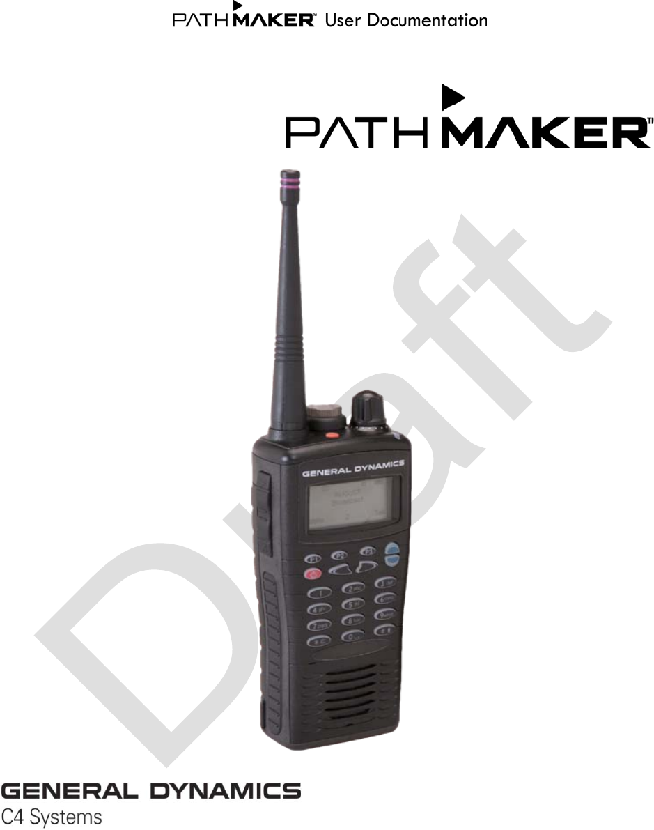
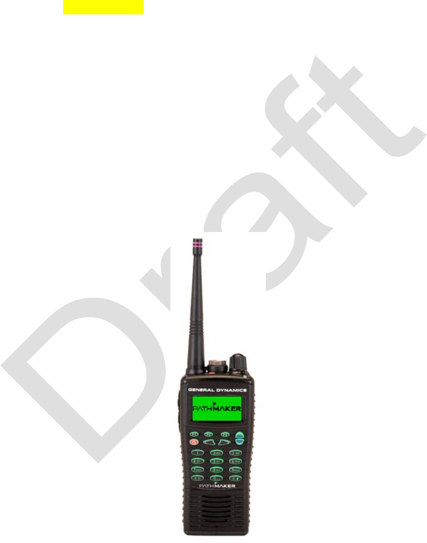
Figure 1 - Pathmaker Radio ............................................................................................ 1
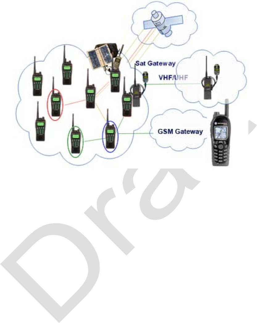
Figure 2 - Network with Gateways .................................................................................. 9
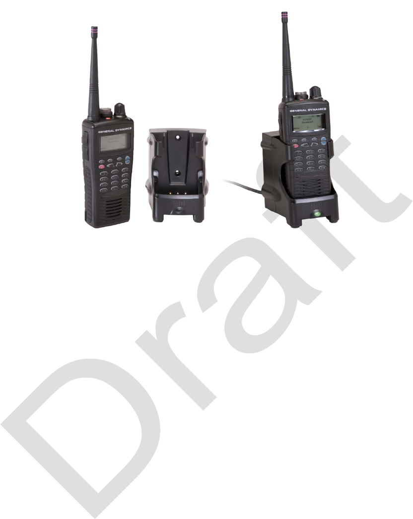
Figure 3 - Charging the Battery ..................................................................................... 11
Figure 4 - Radio Components ....................................................................................... 13
Figure 5 - Main Screen .................................................................................................. 15
Figure 6 - Function Keys ............................................................................................... 17
Figure 7 - Talk Menu Map ............................................................................................. 27
Figure 8 - Settings Menu Map ....................................................................................... 39
Figure 9 - Technician Menu Map ................................................................................... 56

vi
List of Tables
Table 1 - List of Items Furnished ..................................................................................... 5
Table 2 - Accessories ...................................................................................................... 5
Table 3 - Electrical Characteristics .................................................................................. 6
Table 4 - Environmental Specifications ........................................................................... 7
Table 5 - Radio Components ........................................................................................ 13
Table 6 - Talk Options ................................................................................................... 28
Table 7 - Settings Menu Options ................................................................................... 40
Table 8 - Replaceable Parts .......................................................................................... 69

vii
99-P42565K 1
INTRODUCTION
Pathmaker is a voice-oriented, handheld radio communications device providing groups
of users with unlimited mobility and coverage without the need for a fixed infrastructure.
By creating an ad hoc, self-routing mobile network, Pathmaker ensures high quality
voice, data, and video communications together with simultaneous connectivity to
external networks.
Pathmaker offers a simultaneous voice and data wireless mesh network at the end unit
level (radio device, cell phone/PDA, etc.). General Dynamic’s technology enables each
Pathmaker device to function as if it were a voice and data router/repeater. As such,
Pathmaker creates a powerful multi-hop/multi-user dynamic network that extends
coverage to the tactical edge and overcomes the daily issues of infrastructure
dependency, blocked transmissions (walls, metal, dead-spots, climate, etc.) and out-of-
range communication.
Figure 1 - Pathmaker Radio

2 99-P42565K
General Information
Pathmaker Network Radios provide dynamic wireless, mobile, ad-hoc networking
communications without reliance on network infrastructure. Pathmaker Radio users
become their own network, which makes the radios ideal for use in remote locations
where no infrastructure exists or where the infrastructure has been destroyed or
overloaded.
Safety Precautions
Carefully read all of the cautions and warnings before using the radio:
Before using, maintaining, or installing the Pathmaker radio and battery charger,
carefully read and observe all safety recommendations in the relevant technical
manuals.
Do not use the radio equipment for uses other than those indicated in the present
manual.
For correct use of the radio equipment, read and observe all that is listed in this
user's guide.
Do expose the Pathmaker Radio to heat sources greater 60°C.
Do not install or remove the battery when refueling a vehicle or in the presence of
fuel.
Do not place the Pathmaker radio above the airbags or in their area of action. If
an airbag is activated, it may not inflate correctly and/or may hurl the portable
unit, with great force, inside the passenger compartment where the vehicle
occupants are located.
The external antenna connector not used during normal operations must be
protected by a proper cover.
Use the connector covers when the connector is not in use is recommended.

99-P42565K 3
Do not cause short circuits between the battery terminals. Do not place the
batteries on metal surfaces.
Do not place metal tools on the battery terminals.
Do not place battery in a pocket, purse/bag, or any other container with metal
objects.
Replace the batteries with equivalent batteries approved by the manufacturer.
When replacing the batteries, follow the instructions given in the relevant
technical manual.
Do not use batteries that are not damaged, have liquid leaks or evident gaseous
emissions.
Replace damaged radio battery before operating the radio.
When using the battery charger be sure there is adequate ventilation, the power
cord will not be stepped on or tripped on. Do not use the battery charger outside
of the environment for which it is specified.
The battery may vent or explode if the battery is incorrectly installed on the radio.
Even if the battery is discharged it may vent or explode if burned or placed near a
fire.
Use only battery chargers recommended by the manufacturer, and follow all
instructions for using and recharging the battery in the manual.
Do not use the Pathmaker radio if the antenna is damaged.
Turn off the radio, if the equipment enables you to do so, in electromagnetically
sensitive environments (ex. hospitals, airports, etc.).
The Pathmaker radio may cause electromagnetic interference (EMI) to other
equipment if it is not adequately shielded for EMI immunity.
The Pathmaker radio may cause interference with pacemakers or other electro-
medical equipment.

4 99-P42565K
Power the radio off before entering environments which have a potentially
explosive atmosphere (ex. fuel storage sites, filling stations, etc.).
Do not remove or replace the battery while in environments which have a
potentially explosive atmosphere (ex. fuel storage sites, filling stations, etc.).
Do not use the battery charger in environments which have a potentially
explosive atmosphere (ex. fuel storage sites, filling stations, etc.).
All maintenance on the Pathmaker radio must be done in accordance with the
manual.
The Battery Charger and Pathmaker radio (Other than batteries, antennas,
connector covers etc.) have no user replaceable parts and must be returned to
General Dynamics for service.
Use only original accessories and accessories approved by the manufacturer are
suitable for the Pathmaker. The use of different accessories (earphone, antenna,
etc.) invalidates the warranty and may cause a hazard.
Follow the battery charger instructions in order to use it safely.
Do not use the battery charger if the power supply cord and/or plug are
damaged.
The following, while not direct safety precautions are recommended good user practices:
Avoid touching the antenna when the radio is on, because this may reduce the
radio’s range and degrade communications.
When using the earphone, hold the Pathmaker with the antenna straight up and
speak clearly into the microphone.
When using the earphone, do not allow the cord to become wrapped around the
radio or antenna.
Hold the Pathmaker with the antenna straight up and approximately 3 cm away
from your head during voice communications using the loudspeaker.

99-P42565K 5
Modes and Features
• Simultaneous voice, data, and video communications.
• Half-duplex voice calls (Push-to-talk)
• Call types: Private, Group, Broadcast and multi-session
• Quality of Service - voice calls given priority over data packet
• Data packet transfer performed in parallel to voice calls
• Multiple Private data sessions
• Network gateway extension to external legacy communications networks
such as PMR (Tetra, P25) Satellite, GSM, VHF/UHF, SATCOM, IP & PSTN
• Very low energy consumption
List of Items Furnished
Table 1 - List of Items Furnished
Description
Part Number
Pathmaker radio
01-P42559K001
Battery pack (Installed on radio.)
60-P42581K001
User Documentation
99-P42565K
Accessories
Table 2 - Accessories
Description
Part Number
Assembly, Gateway GSM
01-P42570K001
Assembly, Gateway Analog
01-P42573K001
Cable, Pathmaker USB Data
30-P42577K001
Charger, Single Pod 110-230V
60-P42593K001
Charger, Six Pod 110-230V
60-P42594K001
Microphone, Heavy Duty Submersible
50-P42595K001
Earpiece, Rubberized D Shape
50-P42596K001
Earpiece, Transparent Acoustic Tube
50-P42597K001
Earpiece, Rubberized
50-P42598K001
PTT, Large In-Line
50-P42599K001
Microphone, Compact Speaker Mic
50-P42600K001

6 99-P42565K
Electrical Characteristics
Table 3 - Electrical Characteristics
Frequency band
2.4 GHz – 2.485 GHz
Equipment type
2-way radio device
User data rate (max)
Up to 400 Kbps
Static Rx sensitivity
–93 dBm
TX output power
100 mW to 0.5 W
FSK modulation
512KHz deviation
RF channel bandwidth
2 MHz
Encryption
128/256 bits
Audio max power
1 Watt into 8 ohms
Power supply
7.4V Li-Ion 1800 mAh
Dimensions and weight including battery and
antenna
130 (h) x 59.5 (w) x 37
(d) mm, 277g
Air interface ad-hoc protocol
QOLSR variant, multi-
hop best-in-class ad-
hoc networking
Commercial GPS
3-5m, standard NMEA
protocols
(Position Location
Information with GPS)
Data terminal interface RS232, USB
Battery
18 hours on single
battery pack
(AA battery option)
Range 1 km Clear Line of
Sight

99-P42565K 7
Environmental Operation and Storage
Table 4 - Environmental Specifications
Environmental Protection
IP67 submersible 1m for 30
minutes
Military Standard
MIL-STD 810C/D/E/F
Climatic conditions
- ETSI EN 300 019-1-7
- EN 300 019-2-7 class 7.3
Dust and rain protection
IEC 529 class IP54
Operating temperature range
TBD
Storage temperature range
-40°C to +85°C
Transportation conditions
ETS 300 019-1-2 class 2.3
Vibration and shock
- ETSI EN 300 019-1-7 class
7M
- MIL STD 810 E/F – Method
514.4/5 (vibrations)
- MIL STD 810 E/F – Method
516.4/5 (shock)
- Free fall 1 meter height on
concrete surface
Plastic parts
Finishing: compliant to SP-
92100555
Aluminum parts
Color: black, orange, grey;
Paint: epoxy based resin;
Finishing: compliant to SP-
92100555

8 99-P42565K
System
Pathmaker type radios automatically create a self-configuring network without the need
for any fixed infrastructure or base station sites. Each unit automatically acts as a relay
station to other radios if this is required by their deployment pattern and mobility paths.
Pathmaker Network Radios provide a dynamic wireless, mobile, ad-hoc, automatic, self
organized RF mesh network without reliance on network infrastructure. Each
Pathmaker radio functions as a voice and data router/repeater creating a powerful multi-
hop/multi-user dynamic network that extends coverage till the tactical edge and
overcomes the daily issues of infrastructure dependency, blocked transmissions (walls,
metal, dead-spots, climate, etc.) and out of range communication. Because Pathmaker
Radio users become their own network, the radios are ideal for use in remote locations
where no infrastructure exists or where the infrastructure has been destroyed or
overloaded. Pathmaker radios are built for critical missions in challenging conditions
and provide superior simultaneous voice, data, and video communications and allow for
multiple users on a single frequency to conserve spectrum space. With a maximum of
32 radio users per network, users can form traditional squad communications groups, or
extend range and coverage by connecting to multiple networks.
Where legacy network infrastructure exists, the Pathmaker Network Radio System can
take advantage of those networks by providing gateways, thereby increasing the
network’s footprint and reach. Users can form traditional squad communications
groups, or extend range and coverage by connecting to multiple networks. Users can
communicate privately (one-to-one), as a group (one-to-many), multiple group
(broadcast), and have multiple private and group sessions on one RF channel. The
Pathmaker Network automatically indicates what radios are available on the Network
via each radio’s given nickname. As radios leave and enter the network, the available
contact list is automatically updated.
Supported gateways include: GSM Cellular, PSTN, IP, and Analog – including analog
devices such as a UHF/VHF/HF radio (i.e., P25 radios, analog SATCOM terminals,
etc.).
99-P42565K 9
Figure 2 - Network with Gateways

10 99-P42565K
SETUP
Normal setup includes unpacking, inspecting for damage, and charging the battery.
Other setup procedures specific to a particular operating mode are included in the
Operation section of this manual.
Unpacking
Inspect the hardware for damage. Retain the packing material and the shipping
container, if desired, for possible future use. Return shipping label? Instructions?
Charging the Battery
The battery charger provides rapid recharging of the lithium-ion battery pack provided
with the Pathmaker radio. The charger may be placed on any flat surface, such as a
desktop, or it may be bulkhead mounted using the [provided?] mounting hardware. The
battery may be inserted into the charger alone or while mounted to the radio. When
charge is complete, the charger automatically switches to standby mode.
Two chargers are available, a single-unit charger as shown below, and a six-unit
charger. The operation for each is the same.
The normal time to charge a fully discharged battery is 120 minutes.
To operate the charger:
1. Plug the AC power cord of the charger into an AC supply between 100 to 240
VAC. The LED should not illuminate. If it does illuminate, check the AC supply or
replace the charger.
2. Switch the radio off.
3. Insert the battery into the charger, either with or without the radio attached. The
LED will illuminate RED indicating the battery is charging.
4. When the LED illuminates GREEN, charge is complete. The radio may be
removed or may remain in place on the charger.
99-P42565K 11
Figure 3 - Charging the Battery
The LED is normally off when the charger is plugged in and no radio or battery is
installed.
If the LED does not illuminate at all when the radio or battery is installed, check AC
power or try reseating the radio or battery.
If the LED illuminates flashing RED at any time, the charger is defective and should be
replaced.
Precautions
• Keep the charger in a well ventilated, dry place.
• Do not use the charger with any other batteries.
• Do not use the charger as a power supply.
• Never charge a radio that is switched on.
• Never insert metal objects into the charger.
• Do not touch the charger terminals.
• Do not connect the charger to a power source outside the 100 to 240 VAC range.
• Do not disassemble the charger.

12 99-P42565K
OPERATION
This section contains a description of the radio, controls and indicators and operation of
the radio. A detailed description of each menu option is also included.
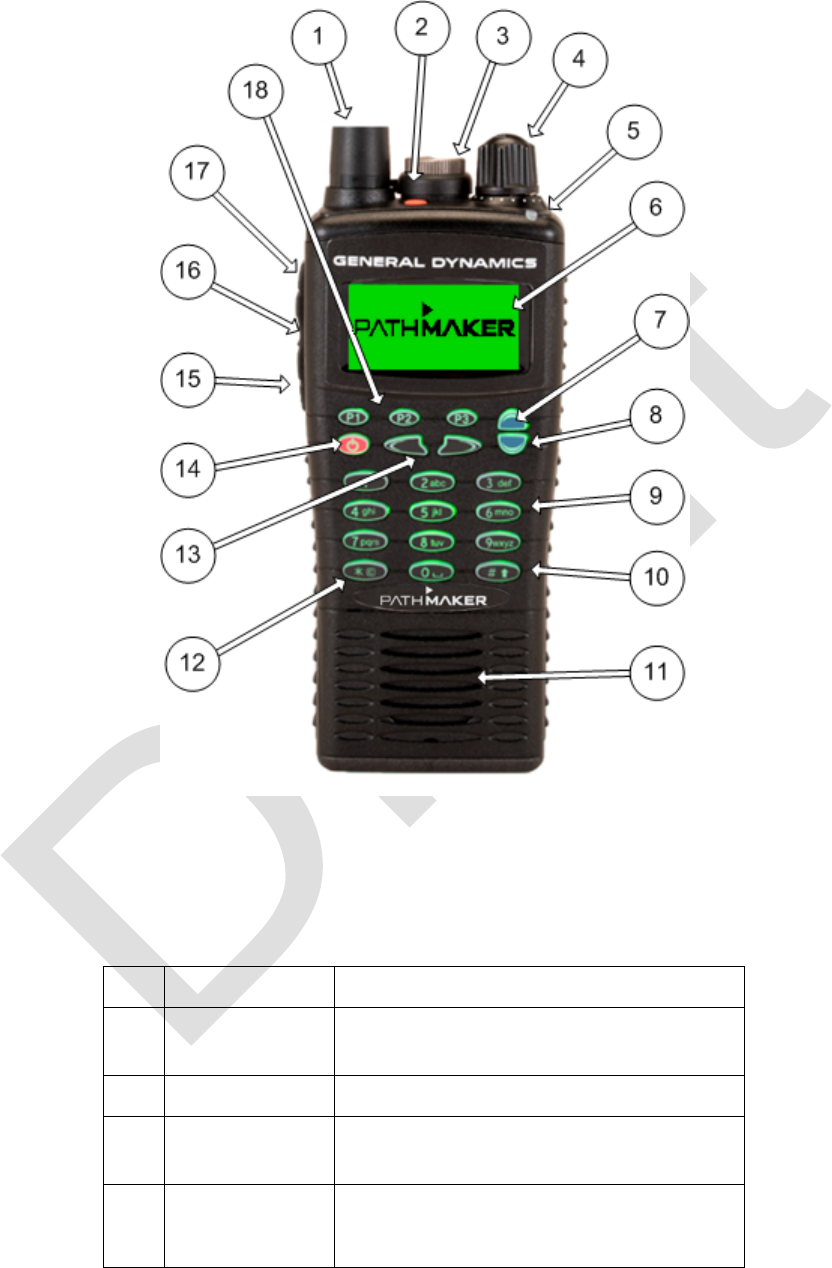
Equipment Description
The front panel contains the display, the keyboard, and an LED indicator showing
outgoing and incoming calls.
The rear panel contains the battery compartment. The left-hand panel contains the push
and push-to-talk buttons.
The top panel holds a receptacle used to connect accessories. It also holds the antenna
connector and rotary switch.
The components are illustrated in the following figure and functionally listed in the table
below. The callouts in the illustration refer to the sequence numbers in the table.
99-P42565K 13
Figure 4 - Radio Components
Table 5 - Radio Components
No.
Designation
Description/Function
1
Antenna
Wireless communication at 2.4 GHz
band
2
Panic
Emergency button
3
Accessory
Connector
USB, Microphone, PTT, Earphone
4
Rotary switch
Multi-function switch:
Rotate to set level of volume or
select menu items.

14 99-P42565K
No.
Designation
Description/Function
5
LED Indicator
Red indicates outgoing call
Green indicates incoming call
6
Display
Displays status of the device and
menu options
7
Scrolling key
Scroll up to select menu options
8
Scrolling key
Scroll down to select menu options
9
Keyboard
Alpha-Numeric keyboard
10
Pound key
Lock or unlock the keyboard.
First press the Asterisk key,
then the Pound key
11
Speaker/MIC
Internal loudspeaker/Microphone
12
Asterisk key
Lock or unlock the keyboard.
First press the Asterisk key
then the Pound key
13
Key
Function Keys
14
Power
ON/OFF
Continuous press (3 sec) ON/OFF
Momentary press back to main
screen
15
Push switch
Cancel (back to main screen)
16
Push switch
Push-to-talk
17
Push switch
Channel list
18
Shortcut
Keys
P1 – broadcast / phone call answer
P2 - private list / phone call send
P3 – group list /phone call end
99-P42565K 15
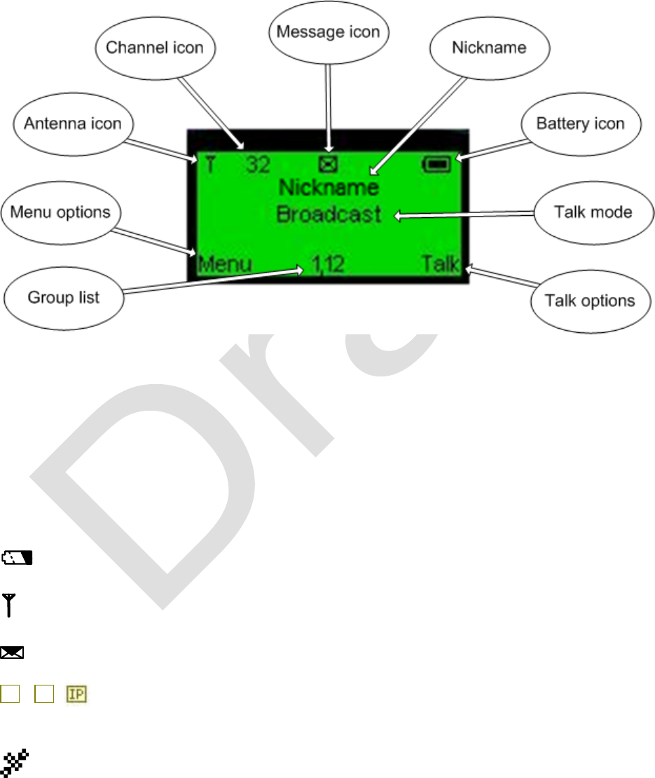
Main Screen
Press and hold the Power ON/OFF key until the unit turns on. This will initialize the unit.
Initialization can take a few seconds. When initialization is complete, the main screen
will appear.
Figure 5 - Main Screen
In this illustration, the radio’s nickname is Nickname, the radio is transmitting on channel
32, the transmission mode is Broadcast, there are two groups - 1 and 12 - in the Group
list, the battery is fully charged, and it is connected to a mesh network (which is
indicated by the antenna icon appearing in the screen). The message icon indicates that
there is an unread text message in the inbox.
Display icons
Battery icon - Indicates the current level of battery power on a five graded scale.
Antenna icon - Indicates location of a valid Pathmaker network.
Messages (Reception) icon - Indicates message reception.
G
,
A
Gateway icons - Indicates the connection to external Gateway. G = GSM,
A = Analog. IP = IP gateway.
GPS – Indicates GPS function.

16 99-P42565K
Headset icon – Indicates headset attached.
Serial cable icon – Indicates connection of serial cable.
Outgoing Broadcast call icon – Indicates outgoing broadcast call from the unit.
Outgoing Group call icon - Indicates outgoing group call from the unit.
Outgoing Private call icon - Indicates outgoing private call from the unit.
Incoming Broadcast call icon – Indicates incoming broadcast call.
Incoming Group call icon – Indicates incoming group call from one of the group
members.
Incoming Group call icon – Indicates incoming private call.
99-P42565K 17
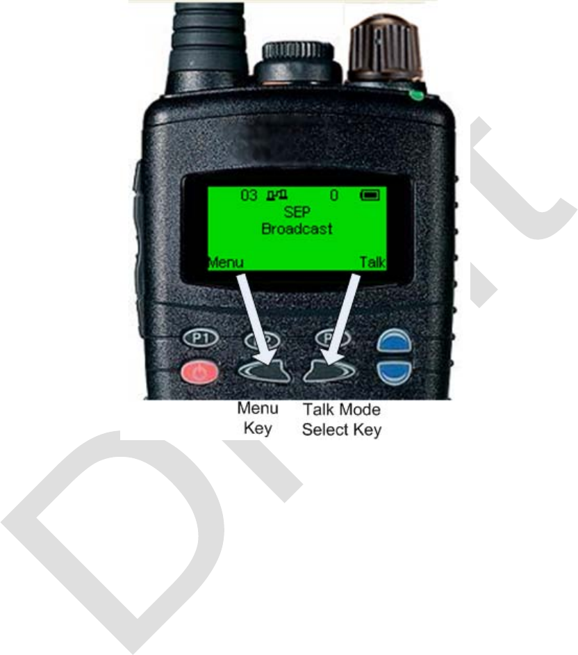
Function Keys
The function keys are indicated on the Menu screen as shown below:
Figure 6 - Function Keys
To open the menu options, press the left function key.
To open the talk mode options, press the right function key.
General Information
There are three general forms of communication when using the Pathmaker radio,
voice, text, and data. Each of which is described briefly below. Step-by-step procedures
are described in detail in below.
Voice Communications
Voice communications take place as they would using any general purpose transceiver.
Once the communications channel and transmit mode (Broadcast, Group, or Private)

18 99-P42565K
are set, press the push-to-talk (PTT) switch to transmit voice messages. Release the
PTT to receive voice.
Text Communications
Text communications take place in much the same way as text messages are
performed in common cell phones. Once the communications channel and transmit
mode (Broadcast, Group, or Private) are set, use the main menu to select Messages
and type the desired message.
Data Communications
Data communications include video and require connection to a computer using the
USB cable. The computer, in turn, is connected to the data source such as a video
camera. The Pathmaker is used to transmit the data to the next link.
Voice Communications
There are four levels of communications and they are called Talk Modes. Each Talk
Mode has a defined priority over the other modes. The Talk Modes are Broadcast,
Group, Private, and Priority. The terms refer to the transmit characteristics of a given
mode. A given talk mode defines which network members are targeted to receive a
message. It does not restrict reception from other radios.
For example, a radio in broadcast mode will be heard by any other radio that is using
the same channel and is also in receive mode (PTT not pressed).
A radio set to the group talk mode will only be heard by radios in the same group.
A radio in private talk mode will only be heard by the radio selected for private
communications. It is like a phone call.
In each of these cases, the transmitting radio will only be heard by radios that are in
receive mode (PTT not pressed) and on the same channel. Other radios that happen to
be transmitting at the time of the call are not affected until they are also in receive
mode.
Priority mode is a special case of broadcast. The transmitting “commander” radio not
only interrupts any currently received communication, it also disables the transmissions
of any radios that are transmitting and places them into receive mode as long as the
Commander’s PTT is depressed.
99-P42565K 19
Finally, the Group Prioritization mode may be thought of as a sub-set of commander
mode. A radio may be set to interrupt both the receive and transmit of a number of
radios in a group selected to had priority over another.
Operating Procedures
Selected basic operating procedures are shown below.
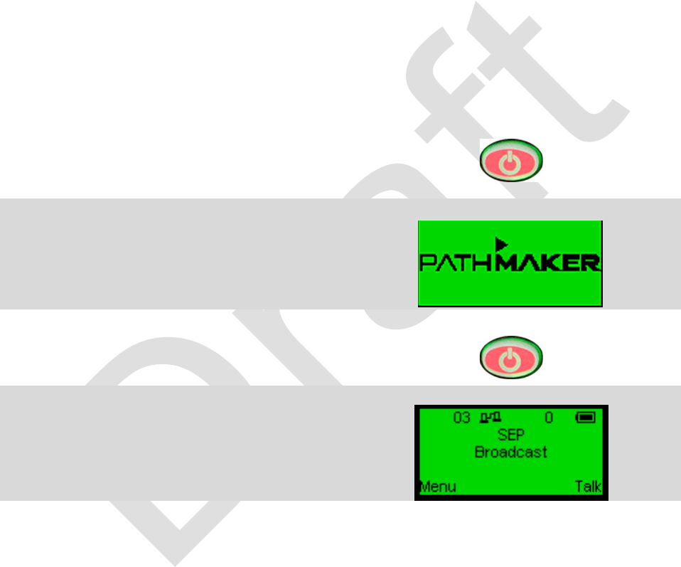
POWER ON/OFF
Power On
1. Press and hold the ON/OFF switch.
2. After a few seconds the Pathmaker
screen will appear.
3. Release the ON/OFF switch.
4. The main screen will appear.
Radio is ready to operate.
20 99-P42565K
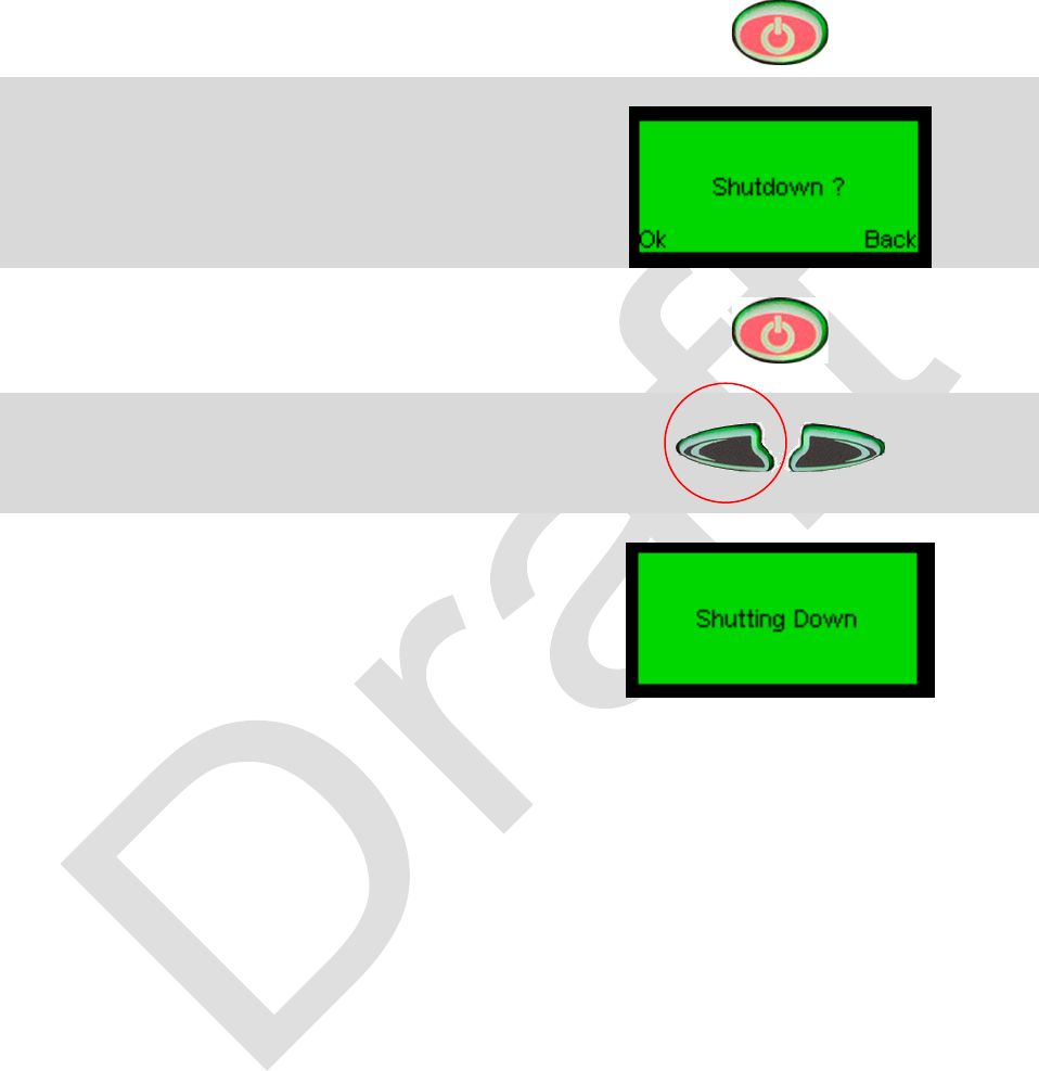
Power Off
1. Press and hold the power ON/OFF
switch.
2. Shutdown confirmation screen will
appear.
3. Release the power ON/OFF switch.
4. Press and release the left function
key to confirm shutdown.
5. Shutdown screen is displayed.
Radio will power off automatically.
99-P42565K 21
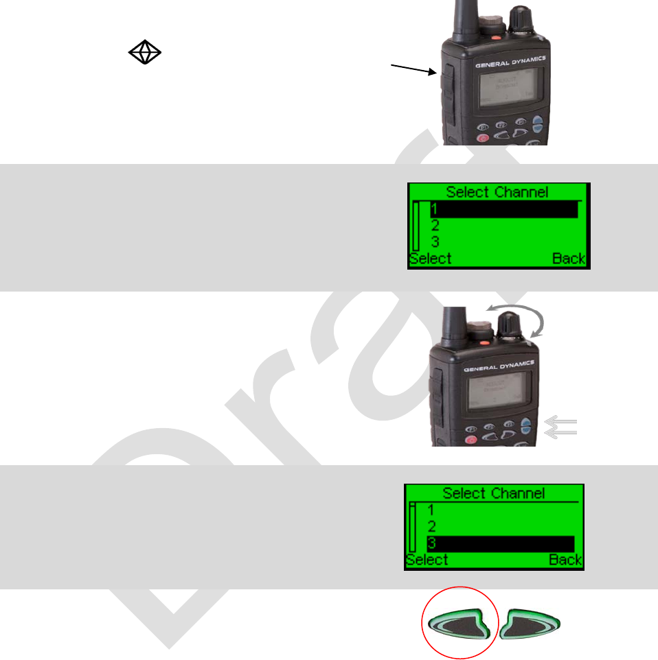
SELECTING A CHANNEL
1. Press and release the channel key.
Marked with .
This is the top third of the push switch.
2. The Select Channel screen will appear.
.
3. Rotate the rotary switch or press and
release the scroll keys to select desired
channel.
4. Highlight desired channel.
5. Press and release the left function key
to save.
22 99-P42565K
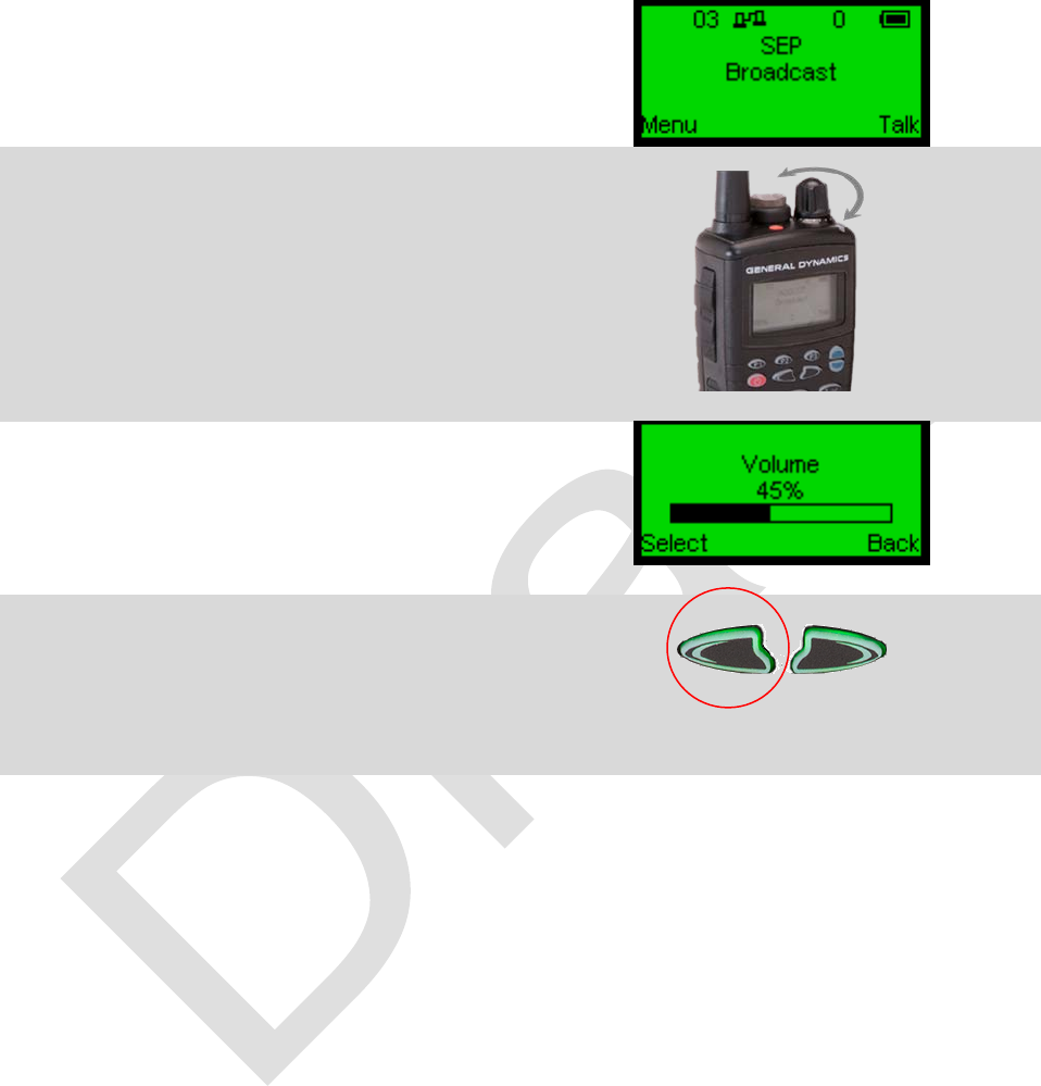
VOLUME ADJUST
1. Begin at main screen.
2. Turn rotary switch to adjust volume.
3. Adjust to desired level.
4. Press and release left function key to
save or wait until display returns to
Main screen.
99-P42565K 23
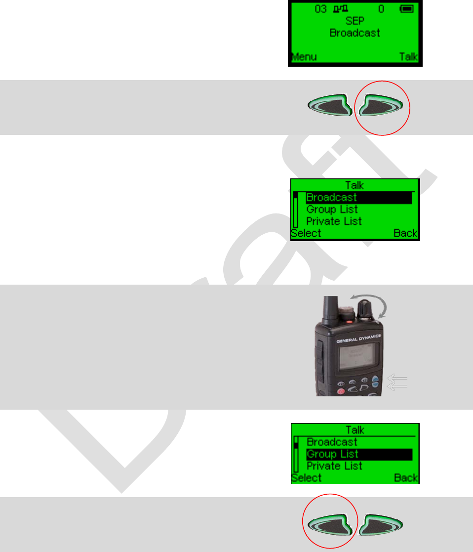
TALK SELECT USING MENUS
1. Start at the Main screen.
2. Press and release right function key.
3. Talk Select menu screen is displayed.
Examples:
Broadcast – Talk with everyone on
same channel.
Group – Talk only with members of
same group.
Private – Talk only with individual
identified by nickname.
4.
Select desired talk mode using rotary
switch or scroll keys.
5. Highlight desired talk mode.
6. Press and release left function key.
24 99-P42565K
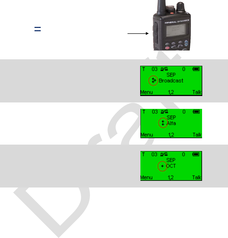
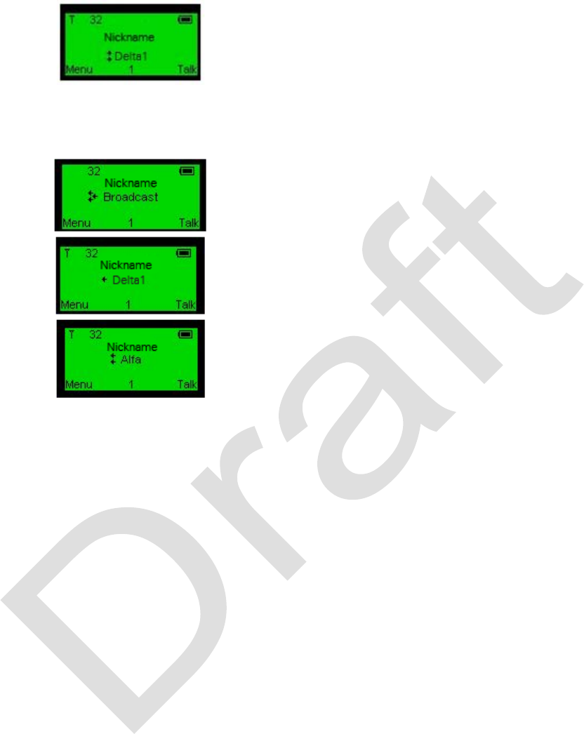
PUSH-TO-TALK
1. Press and hold center of Push-to-Talk
switch.
Marked with: It’s the middle third of
the push switch.
2. Speak into microphone.
3. Three left-facing arrows indicate
Broadcast.
4. Two left-facing arrows indicate Group
call.
5. One left-
facing arrow indicates Private
call.
99-P42565K 25
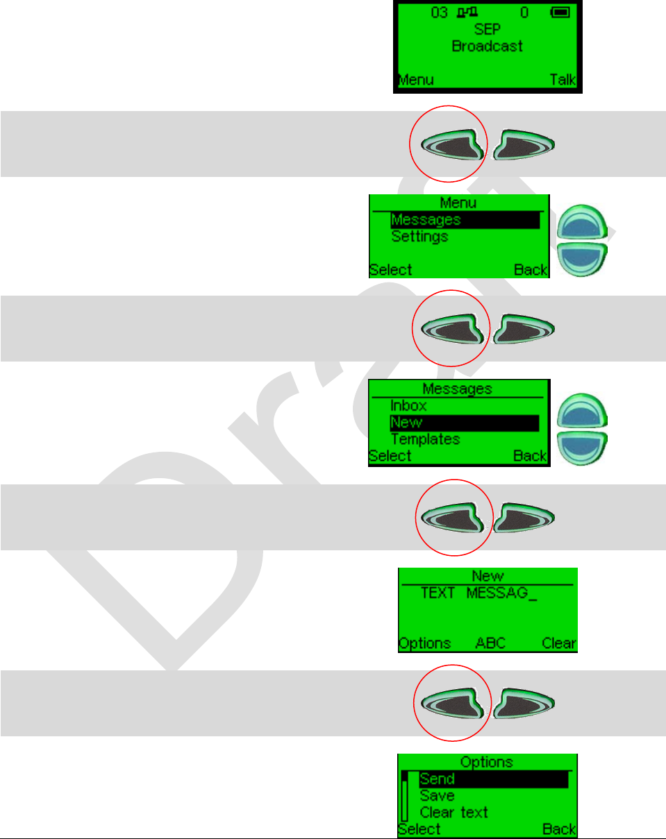
TEXT MESSAGE
1. Begin at main screen
2. Press and release left function key.
3. Use scroll keys to select.
4. Press and release left function key.
5. Use scroll keys to select.
6. Press and release left function key.
7. Type message using keypad.
8. Press and release left function key.
9. Send message.
26 99-P42565K
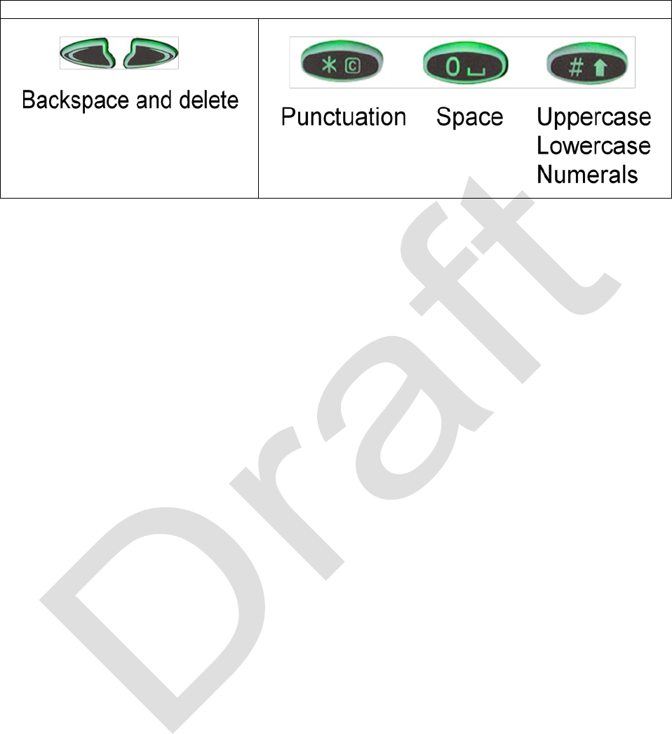
EDIT KEYS
99-P42565K 27
Talk Screen Options
To enter the Talk screen, from the Main screen press the right function key. The Talk
options are listed in the following table.
TALK SCREEN
This screen provides quick access to device communication options, presenting a
selection of users, groups to talk to, GW networks, registering incoming/outgoing calls,
units in panic, and configuring the communication interface according to your personal
preferences.
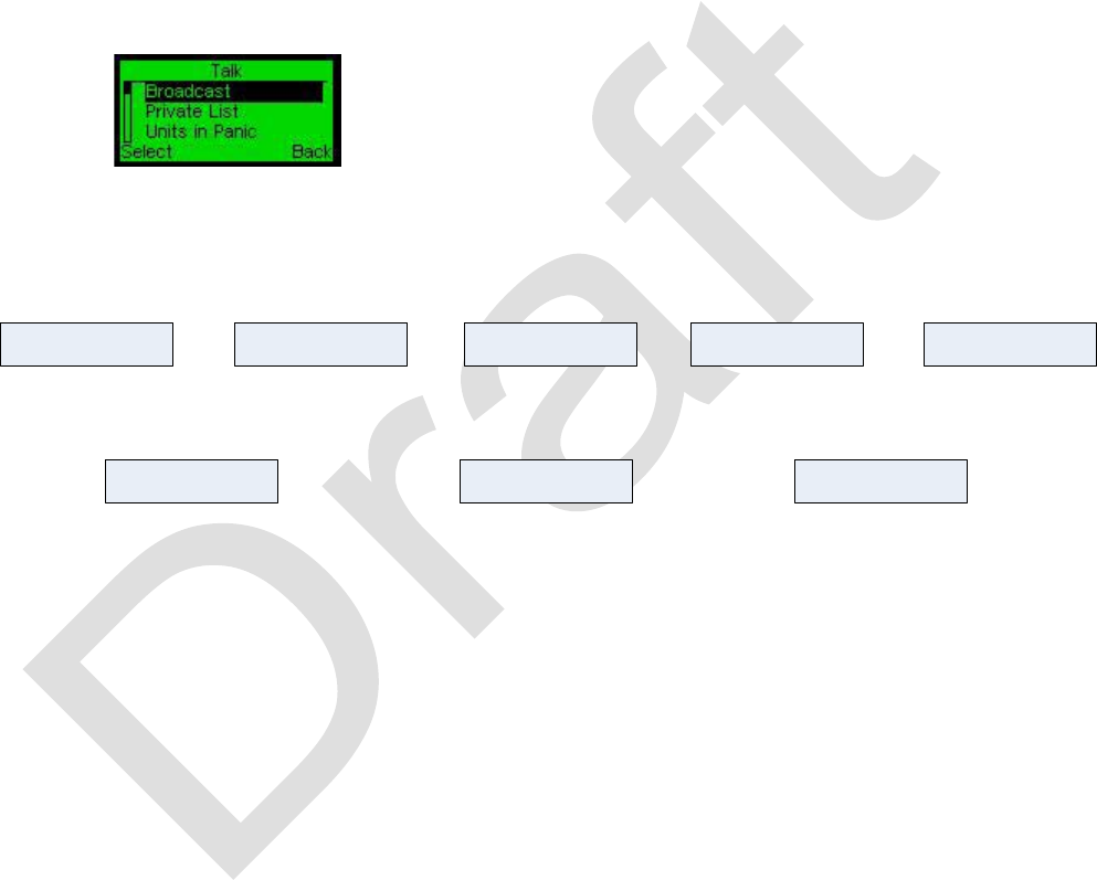
Talk Menu Screen. This screen includes
several options. Scroll to the desired
option using the Up-Down/Rotary keys and
select.
The Talk Menu map is shown below.
Broadcast Group List
• Assigned Groups
Private List
• Radios in network
Units in Panic
• Radios in panic
Incoming calls
• Incoming call list
Outgoing calls
Prioritize Mode
*
Prioritize Group
*
• Outgoing call list
*
Prioritize Mode and Prioritize Group menus are only visible if the Commander mode is set ON in the Technician menu.
Figure 7 - Talk Menu Map

28 99-P42565K
The Talk options are listed in the following table.
Table 6 - Talk Options
1st level
2nd Level
Function
Prioritize
Mode
Broadcast session
overwrites any other
sessions on the network
Broadcast
Talk session to all units
in the network
Group list
Displays the
list of groups
the unit is
related to
Select a group from the
list.
Talk session to units
related to a selected
group.
Private list
Displays the
list of
participants in
the network
Select participant from
the list.
Talk session to selected
unit.
Units in Panic
Select
Displays the units in
Panic mode.
Select a unit to private
talk
Incoming
calls
Displays incoming calls
Outgoing
calls
Displays outgoing calls
SHORTCUTS
Several shortcuts are available to speed navigation of the menus.
P1 - Broadcast
P2 - Private list / phone call answer
P3 – Group list /phone call end
Push Switch (above Push-to-talk switch) – Displays channel list when in main menu
screen.
Power ON/OFF – Momentary depress to go back to main screen.
99-P42565K 29
Note:
The Rotary switch can be used to set volume levels, scroll through menu options, and
scroll channels depending on which screen is displayed. If the Main Screen is
displayed, it will control volume. If a menu screen is displayed it will control navigation to
menus. If the list of channels is displayed, it will control which channel is selected.
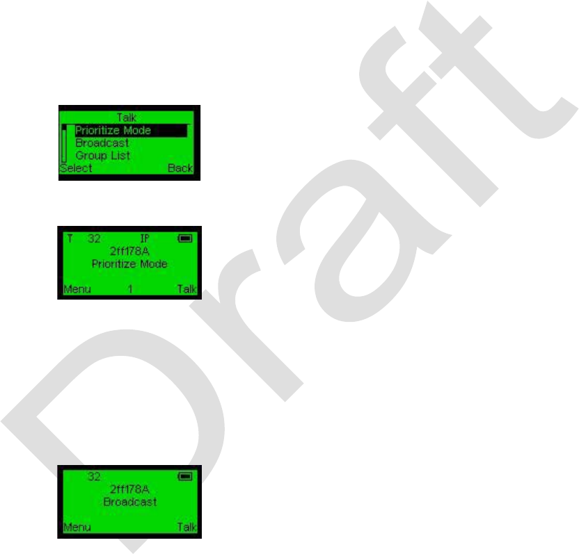
PRIORITIZE MODE
To operate in this mode enter Settings > Technician and set the unit as Commander
On.
In Talk mode select Prioritize Mode. On
the Main menu you are informed that the
unit operates in this mode.
Any broadcast, group, or private call sent
from the unit
operating in this mode
overwrites all other sessions in the
network.
BROADCAST
Messages will be sent to all radios on the same channel.
Sets the unit in Broadcast mode (default
communication mode) and returns to the
Main screen. Pressing the PTT will
broadcast (voice or data) through the
network.
30 99-P42565K
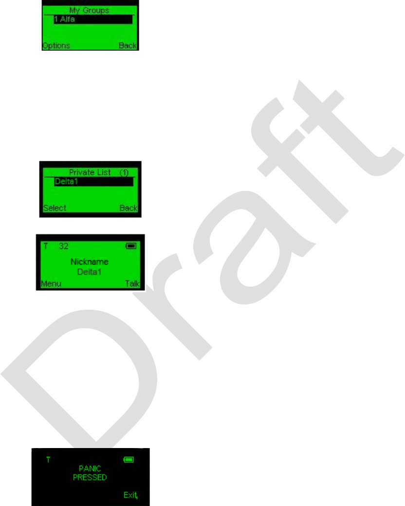
GROUP LIST
Selecting this option will limit your conversations to your group members only.
The group list will be displayed only if you
have groups listed in the My Group list.
Pressing the PTT will connect you (voice
or data) with your group members only.
PRIVATE (POINT TO POINT)
Private selection screen presents a list of existing network nicknames which are part of
network coverage at a given moment.
Call destination selection screen.
To select a call destination, scroll to the
desired nickname and press Select. The
display will return to the Main screen
showing your interlocutor.
Main screen showing outgoing private call.
UNITS IN PANIC
Panic mode
In Panic mode, the communication mode of the unit is set to continuous broadcast of a
panic alarm signal and stays in that mode until the communication mode is manually
changed. This mode does not disrupt the regular communication functions
(incoming/outgoing voice communications).
To activate panic mode, press and hold
down the panic button (red button on top
of the unit). The screen indicates panic
pressed.
99-P42565K 31
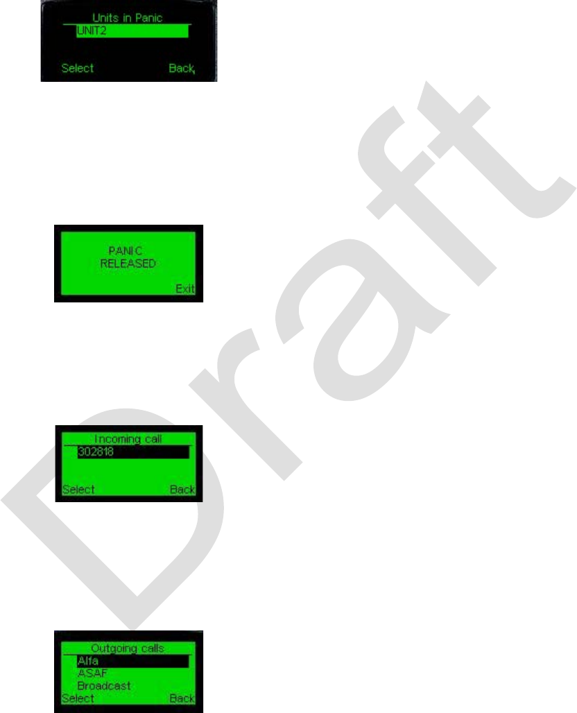
When in “panic pressed” status, all units will automatically change to Panic screen
displaying the list of units in Panic mode. Panic mode overrides groups and private
modes.
You may establish a private call with a unit
from the list by selecting it.
Units in Panic
screen appears on your
unit (black background), showing the list of
all units in panic.
Selection of a unit returns the display to
the Main
screen, switching the
communication mode to Private, with the
selected unit.
To deactivate Panic mode, again press
and hold down the Panic button. This will
return the display to the Main Menu
screen via the Panic released screen.
INCOMING AND OUTGOING CALLS
Incoming Calls screen allows you to select from among the last 10 incoming calls for
calling back. It is a very convenient way to reply to a private call.
From the Main Screen, press the right
function key and select Incoming calls.
OUTGOING CALLS
The Outgoing Calls screen allows you to view or select from among the last 10 outgoing
calls to repeat the call.
From the Main Screen, press the right
function key and select Outgoing calls.
Pressing the Answer button from the Main
screen will get you to the Outgoing calls
screen as well.

32 99-P42565K
Using the Pathmaker Radio
The Pathmaker radios can be set to function as a general User, Commander, Relay and
Bridge device, depending on a given scenario.
User – The User function is the most common. No special setup is required other than
selecting a channel and pressing the PTT switch for voice communications in the
Broadcast, Group, or Private modes. Text messaging is also performed in this mode of
operation. To send a text message, from the Main Screen, press the left function key
and then select New to enter the desired text.
Commander – The radio designated as a Commander has voice priority of all other
radios in a network. No matter what other voice communication is taking place
(Broadcast, Group, or Private) the Commander’s message takes priority.
To set a radio as a Commander, from the Main Screen select Settings > Technician >
Commander ON.
Relay – Any radio can automatically serve as a relay device without user intervention.
However, in some scenarios, it may be beneficial to designate an unattended radio as a
relay to connect other members of a network who are otherwise out of range. In this
mode, the radio keyboard is locked, the display and LED are dimmed and the volume is
muted.
To set a radio as a relay station, from the Main Screen select Settings > Technician >
Drop Down > ON.
Main Screen
INCOMING AND OUTGOING CALLS
Incoming calls are displayed on the Main screen as follows:
Incoming Broadcast Call On Main Screen
Incoming Private Call On Main Screen
99-P42565K 33
Incoming Group Call On Main Screen
The LED will become green when an incoming call is received.
Outgoing calls are displayed on the Main screen as follows:
Outgoing Broadcast Call On Main Screen
Outgoing Private Call On Main Screen
Outgoing Group Call On Main Screen
When pressing the PTT or when voice transmission is activated, the LED indicator turns
red.

34 99-P42565K
MENU SCREENS
In the main screen, press the left function key. Two options are available, Messages
and Settings.
The Menu screen lists the options.
Scroll to the desired option and press
Select (left function key).
MESSAGES
Pathmaker can send and receive short user inputs and predefined messages through
the network and external interfaces. The predefined messages are listed in the
Templates screen. Newly received messages are saved to the Inbox.
The following table lists the menu options.
Messages Menu Options
1st level
2nd
Level
3rd Level
Function
Inbox
Option
Select
View incoming
messages
Details
Details of a message
Send
Send a message
Erase
Erase a message
Erase All
Erase all messages
New
Option
Send
Send a message
Save
Save a message
Clear text
Clear a message
Back
Back to the previous
level
Exit
Exit menu options
Templates
Any message which
can be used as a
template
99-P42565K 35
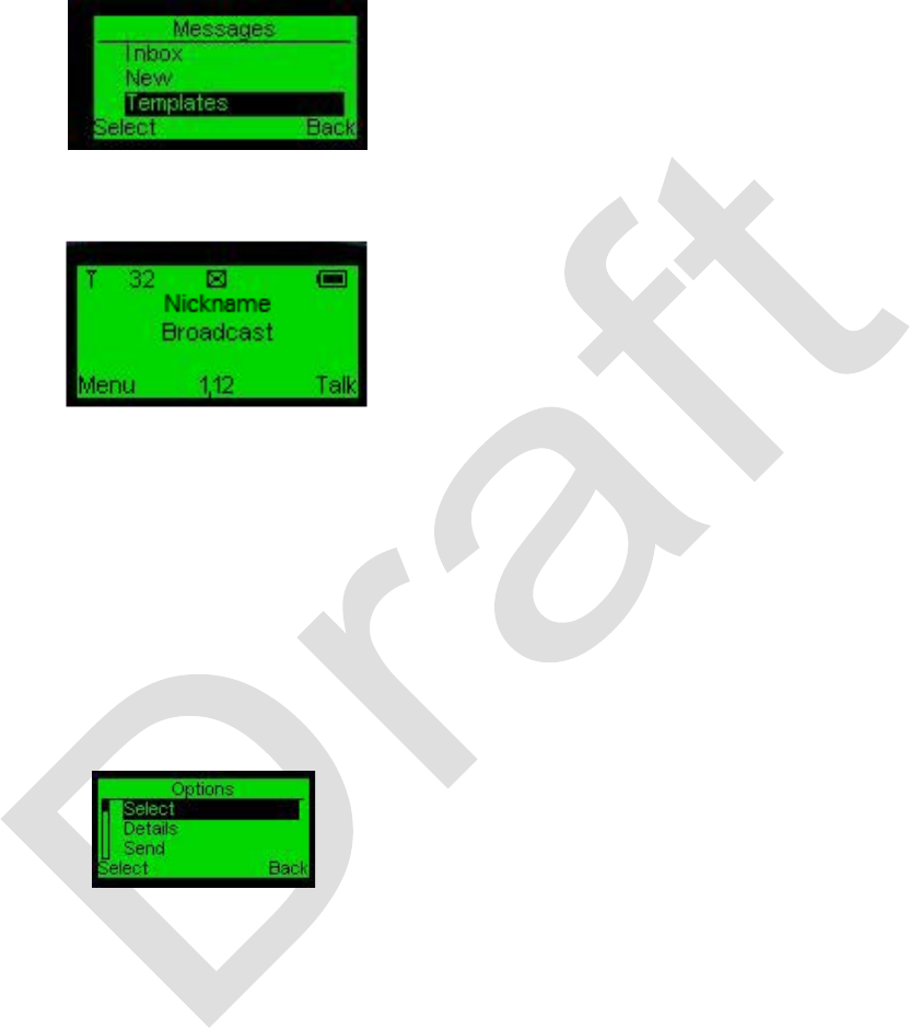
MESSAGE MENU SCREEN
Select Messages from the main Menu screen.
Messages Menu Screen
Select the appropriate message
format (Inbox for incoming
messages, New for outgoing
message and Templates for sending
predefined outgoing message).
Messages Received Screen.
When a message is received, the
Message (reception) icon will pop
up. Go to Inbox to view the
message.
If the message is received, a small
envelope-shaped icon is displayed.
MESSAGES - INBOX
MESSAGES – INBOX - OPTIONS
This screen allows you to manage your messages.
To display the message (new or template),
choose Select. Select Details
to view
received message details. The Details
screen will appear.
Choose the Send option in case you want
to forward the message. A window
showing you the sending modes
(Broadcast, Group, and Private) will
appear, allowing you to choose the
sending mode. After sending, you will see
a sending completion notification on the
screen.
To erase the message, choose Erase. The
inbox message will be erased. Use Erase
All for all inbox messages.
Select Back to return to the Inbox screen
or press the END button to return to the
36 99-P42565K
main screen.
To display the message (new or template),
choose Select. Select Details
to view
received message details. The Details
screen will appear.
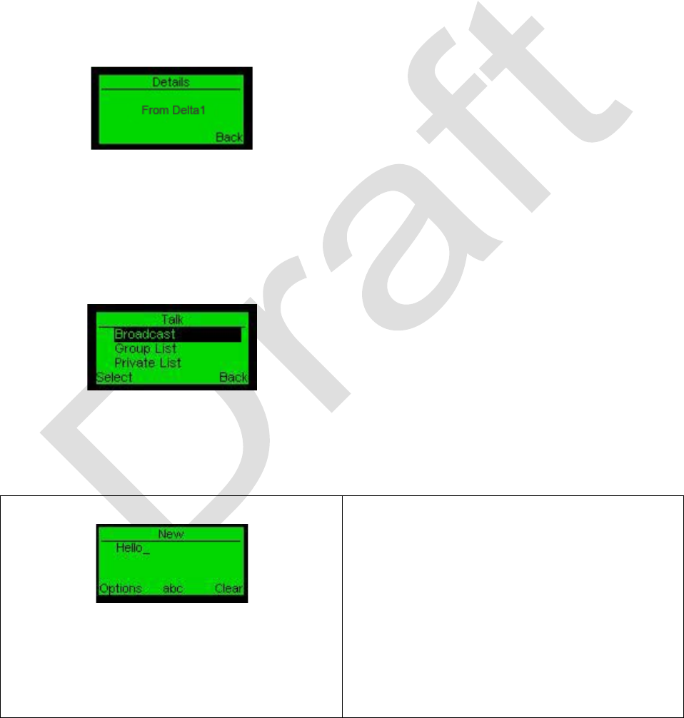
MESSAGES - OPTIONS - DETAILS
This screen shows inbox message Sender.
Inbox Message Details Screen.
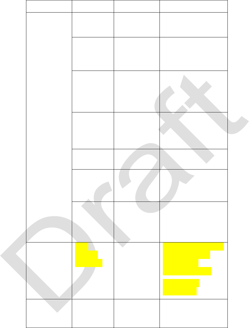
MESSAGES - OPTIONS - SEND
This screen shows the sending modes list. Select the relevant mode for sending your
message.
Inbox Sending Modes Screen
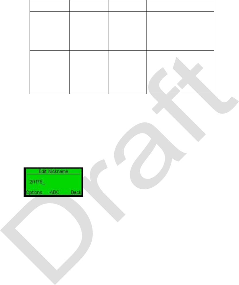
MESSAGES - NEW
This screen allows you to compose new messages.
New Message Screen.
To compose a message, use text buttons.
You are limited to 160 characters at the
most.
Use the pound key “#” to change between
"ABC" -
signing the upper case letters,
"abc" -
signing the lower case letters and
"123" - signing the digits from 0 to 9. Use
the asterisk key “*” to add symbols.
Use the Clear option to erase text.

99-P42565K 37
MESSAGES – NEW - OPTIONS
The Options screen allows you to manage the newly-written message.
New Message Options Screen
Use Send
to send the message out. A
screen with sending
modes will appear
(choose the sending method – Broadcast,
Private or Group). After sending, you will
see a sending completion notification on
the screen.
Use Save
to save the message to the list
of templates.
Use Clear text to clear message text and
go back to "New” message screen.
Use Exit to return to Main screen.
Press Back to go back to the New
message screen.
MESSAGES - TEMPLATES
This screen contains a set of predefined messages saved by the user. Every newly-
saved message will appear as a template.
To add a message to the Template list, go
to Messages > New. Create the message
and then press Options > Save. The text
will be saved to the templates list.
Scroll up/down to the desired message
using the up-down/rotary keys, and press
Options (left function key). The Options
screen will appear.
MESSAGES - TEMPLATES - OPTIONS

38 99-P42565K
This screen allows you to manage your template message(s).
Template Options Screen.
To view the template message
, choose
Select.
To send the message, choose Send.
A screen with sending modes displays
(select the sending method – Broadcast,
Private or Group). After sending, you will
see a sending completion notification on
the screen.
To erase the message, choose Erase. The
template
message will be erased. Use
Erase All to erase all template messages.
Press Back to return to the templates.
Settings
The Settings screen allows you to configure various device settings; Accessibility
settings - such as interface language, themes, display fonts, contrast, volume and a
MIC sensitivity option; advanced settings such as Nickname, My Groups, Add Group,
Radio Channel, Serial interface Baud rate, Matrix of the network, Dark mode, Save
mode and Technician mode.
Settings Screen.
Scroll to the desired option and use the
Select option.

99-P42565K 39
Edit Nickname
• Edit Screen
My Groups
• Assigned Groups
Add Group
• Group List
My VLANs
• Assigned VLANs
Add VLAN
• VLAN List
Matrix
• Matrix Screen
GPS GPS Setup
• Coordinate Screen • Interval
• GPS GW/Type EP
• GPS On/Off
• Distribute On/Off
• Send PC On/Off
• RS232
• USB
Com Ports Accessibility
• Language
• Contrast
• Volume
• MIC Sensitivity
Save Mode on/off
Voice FB on/off Alert Tones Select Channel Remote Update Technician About
• Panic on/off
• Busy on/off
• Out of Service on/off
• Net Join on/off
• Sms on/off
• Power Up on/off
• Power Down on/off
• Volume on/off
• Low Battery on/off
• Select channel
• Edit Groups
• Remote Update ►
• Master Reset
• BER Meter ►
• Listen Mode on/off
• Key Locked on/off
• Drop Down on/off
• Emergency on/off
• PTT auto/on/off
• Crypt ►
• Show ID on/off
• Commander on/off
• GW Sound on/off
• Matrix Setup ►
• Debug Level ►
• Compilation Date
• About
Dark Mode on/off
NOTE: The ►symbol indicates additional menus.
Figure 8 - Settings Menu Map

40 99-P42565K
Table 7 - Settings Menu Options
1st level
2nd Level
3rd Level
Function
Edit
Nickname
Option
Set
Back
Set nickname.
Back one level.
My Groups
Displays
list of
groups
currently
assigned
to the
radio. Max
of two.
Prioritize
(Only if
Commander
mode is set
ON.)
Delete
Selected
Group
Prioritize selected
group.
Cancel assignment
of the selected
group.
Add Group
Displays
list of all
groups.
Displays list of
groups can be
related to. Max of
two.
My VLANs
Displays
list of
VLANs
currently
assigned
to the
radio. Max
of two.
Add VLAN
Displays list of
VLANs can be
related to. Max of
two.
Contact List
*
Options
New
Add new contact to
the list
Delete
Delete contact from
list
Edit Name
Edit selected
contact name
Edit
Number
Edit selected
contact number
Info
Contact Information

99-P42565K 41
1st level
2nd Level
3rd Level
Function
Send
Contact
Send contact
information to other
units in the network
Matrix
Scroll
between
the 4
displays
Display network
connectivity with
other units
GPS
Displays location
coordinates
Info
Displays list of
received satellites
GPS Setup
Interval
GPS data transmit
in seconds. Range
from 4 to 250
seconds.
GPS GW
Type EP
Set the device as
GPS GateWay or
EndPoint *
GPS
ON/OFF
Toggle switch turns
the device GPS
option On or Off
Distribute
ON/OFF
Toggle switch turns
the device GPS
distribute option On
or Off
Send PC
ON/OFF.
Toggle switch turns
the GPS data
transmit to PC
option On or Off
* The radio can function as GPS Gate Way or End Point.
Gate Way transmits GPS data of all devices connected to the network at preset
intervals (in seconds) to the PC.
End Point transmits GPS data only of his location to the PC at preset interval.

42 99-P42565K
1st level
2nd Level
3rd Level
Function
Com Ports
RS-232
USB
Baud rate
921600 default
Loopback
ON/OFF
Activate Local
Loopback. Test
purposes only.
Alarms
ON/OFF
Activate transfer of
alarm messages via
USB
Activate
ON/OFF
Activate USB
communication port
Accessibility
Language
English
Select from list
Contrast
Set the contrast of
the display
Volume
Set the volume of
the speaker
MIC
Sensitivity
Set the sensitivity of
the microphone.
Maximum
recommended
setting is 75%.
Save Mode
ON/OFF
ON – If device is not
used for 13 sec,
display will be
dimmed
OFF – display
illuminated
continuously
Dark Mode
ON/OFF
ON – No display
illumination
OFF – display
illuminated
continuously unless
Save Mode is set
ON. (See above.)
Voice FB
ON/OFF
Activate audible
channel feedback
99-P42565K 43
1st level
2nd Level
3rd Level
Function
Alert tone
Busy
ON/OFF
Activate tone when
the called party is
busy
Out
service
ON/OFF
Activate tone when
the called party is
out of network
service
Net Join
ON/OFF
Activate tone when
the unit joins
network
(get ID from the
network)
SMS
ON/OFF
Activate tone when
text message
(SMS) is received
at the unit
Power Up
ON/OFF
Activate tone when
the unit turns on
Power
Down
ON/OFF
Activate tone when
the unit turns off
Volume
ON/OFF
Activate tone when
volume level
changes
Low
Battery
ON/OFF
Activate tone when
battery voltage
passes low
threshold level.
What is the
threshold?
Select
Channel
1 – 40
channel
range
Select channel
from the list
44 99-P42565K
1st level
2nd Level
3rd Level
Function
Technician
Enter code to
access technician
menu
About
HID
NID **
SW
HW
Hard ID of the unit
Network ID of the
unit
Software version
Hardware version
*Contact list provides information and ability to communicate with GSM or legacy
networks via relevant gateway.
** The unit can operate with devices of the same NID.
SETTINGS - EDIT NICKNAME
Nicknames are used to uniquely identify a given radio. Nicknames are optional but
greatly enhance user identification. This screen assists you with creating and editing a
nickname.
Edit Nicknames Screen.
Enter a Nickname for your unit by using
the text buttons. Use #
button to change
between "ABC" - enters the upper case
letters, "abc" - enters
the lower case
letters and "123" - enters the digits from 0
to 9. To erase text use the down scroll
key.
Use the Back
option to return to the
Settings screen.
Select Options to set or cancel your
nickname.
99-P42565K 45
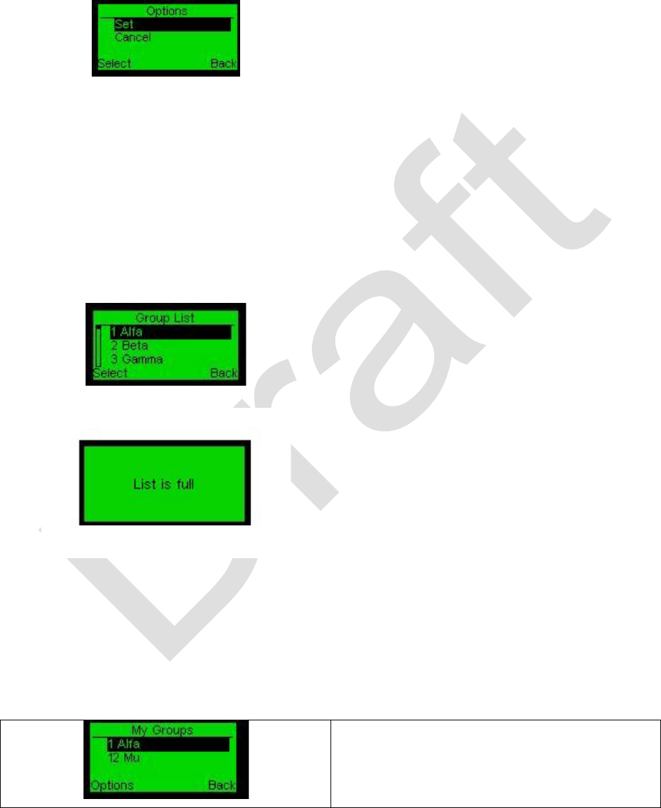
SETTINGS - EDIT NICKNAME - OPTIONS
This screen allows you to Set or Cancel the setting of the nickname you entered.
Nicknames Options Screen
Choose the option and press Select. The
Back option will return to the Edit
Nicknames screen.
Use the Back option to return to the
Settings screen.
Use Scroll down Key for “Clear
character” function.
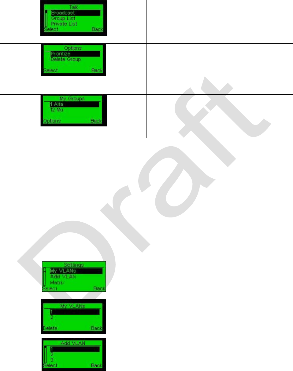
SETTINGS - ADD GROUP
Groups are used for selective voice communications with other members of the same
group. This screen assists you to add groups to the My Groups list.
Add Group Screen. Add the group by selecting
it from the list. Membership in a maximum of
two groups is allowed. The group list is
editable in the Technician menu, which is
described below. The Back option will bring
you to the Setting screen.
Group List Full Notification. If there are
already two groups listed and you intend to
add an additional group, “List is full”
notification is displayed.
The My Groups screen will automatically
display, allowing you to delete a group from
the list to make room for other groups to be
added.
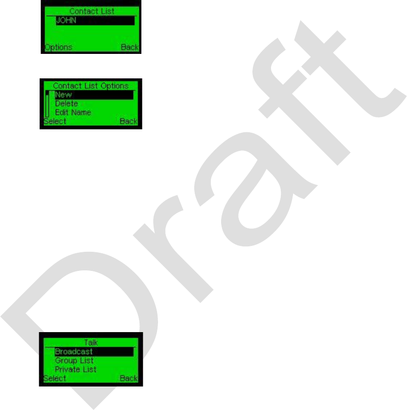
SETTINGS - MY GROUPS
This screen allows you to see the groups you belong to. You can be part of at most two
groups at a time.
My groups screen showing the two groups
this radio belongs to.
46 99-P42565K
Upon becoming a group member, Group List
will be added automatically to your Talk
screen menu, and the added group numbers
will appear on your main screen.
My Groups Options Screen.
Entering the Options screen allows you to
prioritize one of the groups, or delete it from
the My Groups list. Pressing the Back option
will take you back to the Menu screen.
In order to communicate with your selected
group members only, enter the Group List
from the Talk screen or press P3 (group list
shortcut key) and choose the desired group.
Note:
If a unit must not be part of a group, the My Groups list can be empty. Being part of a
group will allow Group communication mode within the network.
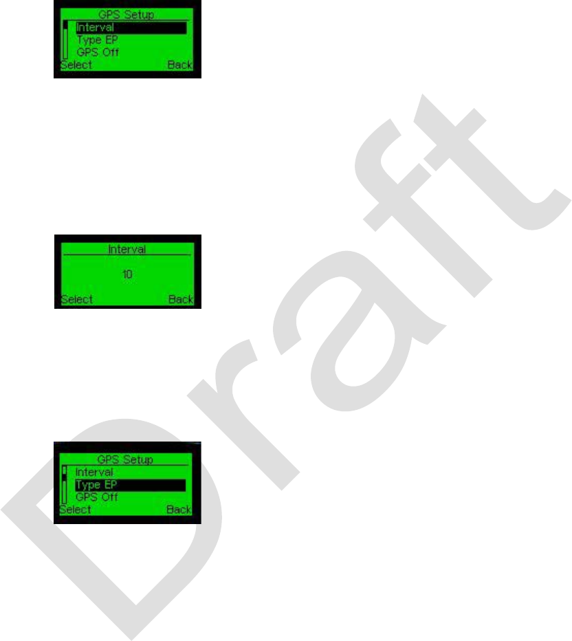
SETTINGS – MY VLANS
VLANs are used for selective data communications (such as video) with other members
of the same group. VLANs are used with data communications in much the same way
Groups are used for voice communications. Up to two VLANs may be assigned to a
given radio.
To see a list of assigned VLANs, Select My
VLANs.
My VLANs Screen, This screen displays the
list of active VLANs. Scroll down the screen to
view the list and then select the relevant
VLAN. To remove a VLAN select Delete.
Add VLANs Screen, This screen assists you to
add more VLANs to the My VLANs list.
To add a VLAN, select Add VLAN, scroll to the
desired VLAN and press the Select (left)
function key.
99-P42565K 47
SETTINGS - CONTACT LIST
If your Pathmaker network is connected to a legacy network via GSM gateway, you can
enter any phone number and save it for future options.
Note:
For this feature to function as described, the call function must be operational and the
GSM gateway must be connected.
Contact List Screen. The Contact List
holds the all phone numbers and names
associated with the phone number.
Contact List Options Screen. Select Options
to access further options from the list.
New: Add a new number or name to the
list.
Delete: Delete a number or name from the
list.
Edit Name: Select any name from the list
to edit it.
Edit Number: select any number from the
list to edit it.
Info: Displays information about a selected
entry.
Send Contact: Select the mode of
transmission from the list.
Send Contact Screen.
The options are:
Broadcast: Sends a message to all
radios within Broadcast range.
Group List: All radios associated with
that group on the network will receive the
message.
Private List: Only the radio with selected
nickname will receive the message.

48 99-P42565K
SETTINGS – MATRIX
This screen displays the connectivity map of your network.
Matrix screen. The network units are
displayed in boxes. Units with black
background are relay stations and units
with white background are regular stations.
The number of units in the Network is the
number of boxes which appear in the
Matrix screens.
You can browse Matrix screens using the
Left function key. There are four screens,
each showing 8 devices. The matrix
screens display up to 32 units in your
network.
You can recognize your unit by me
beneath the box representing your unit,
(icon numbered “
0” in this case). The
number in the box displays the ID number
of the unit in the network.
SETTINGS – GPS
GPS information can be viewed and managed using the GPS and GPS Setup menus.
Select GPS to display the current
coordinates.
99-P42565K 49
SETTINGS – GPS SETUP
The following GPS Setup screens assist you to handle the GPS setup and GPS
functionality of the device.
Scroll down the list to select the
appropriate action.
SETTINGS – GPS SETUP - INTERVAL
This screen enables you to set the time interval (in seconds) the device transmits its
position to the other devices in the network and to the PC.
Select Interval on the previous screen
then apply the Scroll keys to set the time
interval and then press Select.
SETTINGS – GPS SETUP - GPS GW/ EP TYPE
This screen sets the GPS data kind functionality of the device.
GPS GW/Type EP screen. Gate Way
transmits GPS data of all devices
connected to the network at preset
intervals (in seconds) to the PC.
End Point transmits GPS data only of this
location to the PC at preset interval.
50 99-P42565K
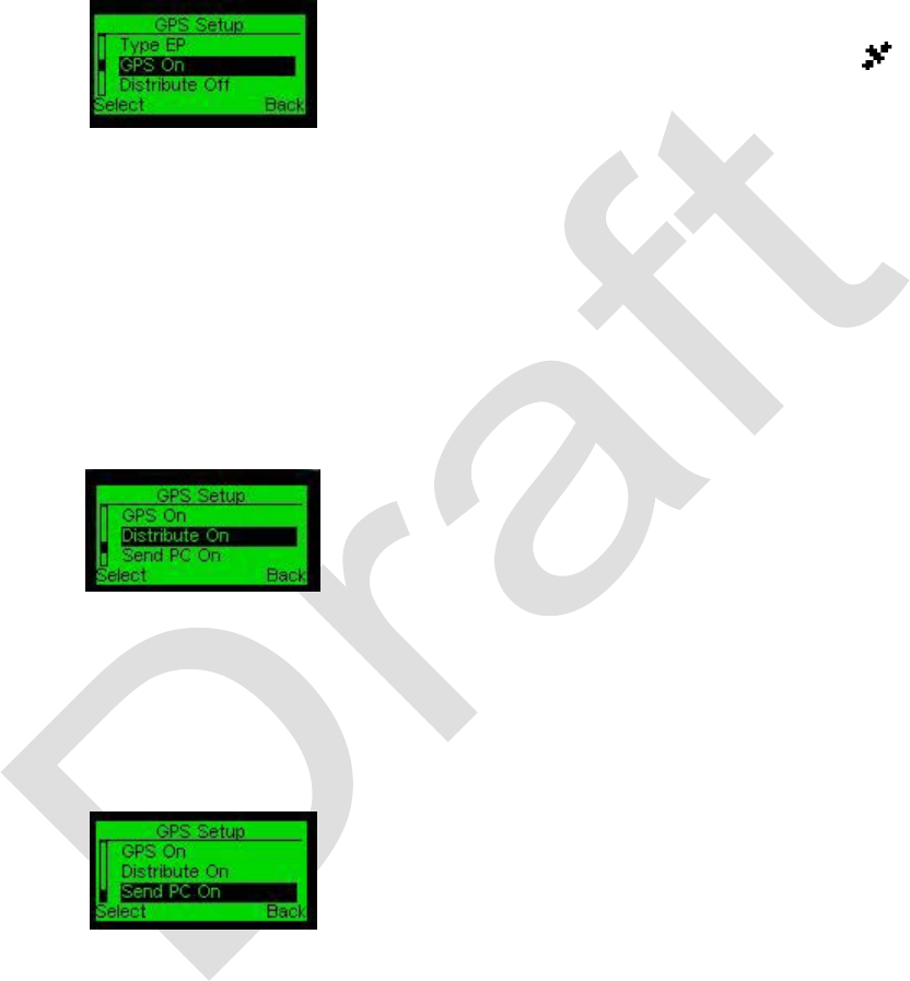
SETTINGS – GPS SETUP - GPS
This screen assists you to turn On or Off the GPS module of the device.
GPS On/Off Screen.
• If GPS function is On, the main
screen displays the satellite icon.
• The phantom view icon indicates that
the GPS module is on but not "locked
to a satellite".
• The icon turns to into black after
locked to a satellite.
SETTINGS – GPS SETUP- DISTRIBUTE ON/OFF
This screen assists you to stop or start GPS data distribution toward other devices in the network.
• Distribute On – GPS coordinates are
sent to all other units in network.
• Distribute Off - GPS coordinates are
not sent to all other units in network.
SETTINGS – GPS SETUP- SEND PC
The collected GPS data can be forwarded to a PC.
Turn the option to On to activate this
function. Connect the radio to the PC over
the USB cable.
99-P42565K 51
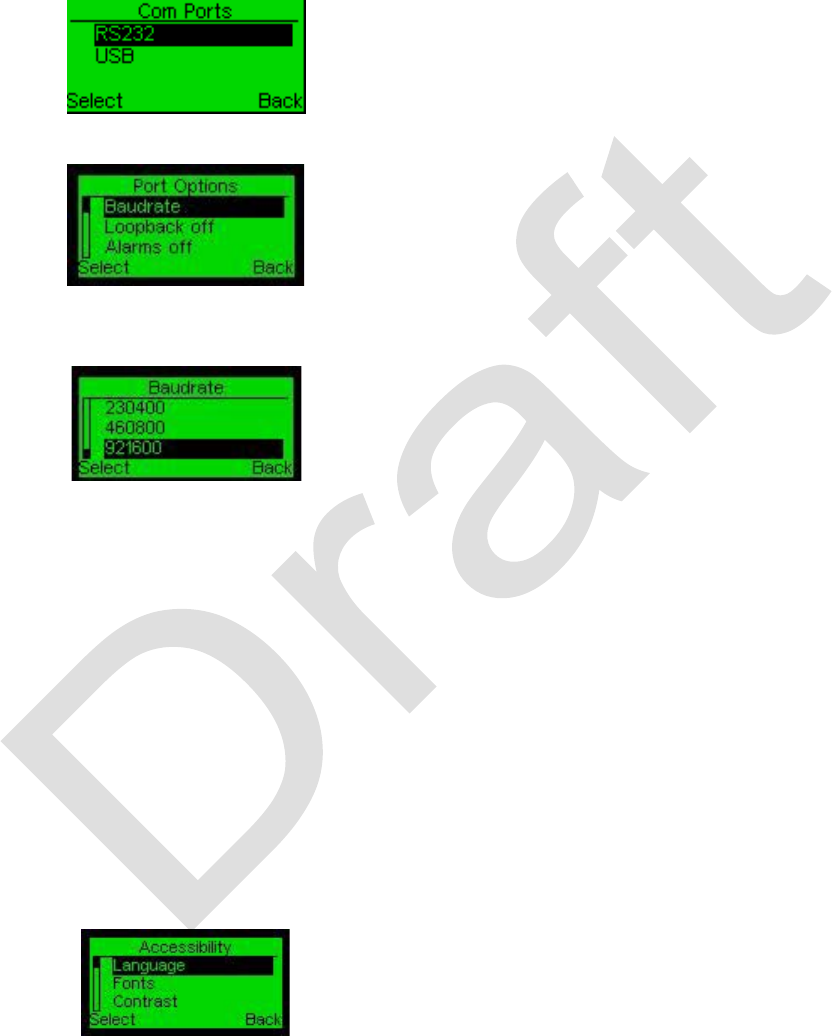
SETTINGS – COM PORTS
Select the applicable serial communication port and connect the cable. The USB
receptacle is located on the top of the unit.
Com Port Selection Screen.
Use this screen
to set the USB or RS-232 port.
Port Options Screen.
After you select the
applicable port, the Port Options screen
displays.
Select the applicable option from the list.
Baud Rate Adjustment Screen
The baud rate screen allows you to set the
serial baud rate of the unit.
The baud rate settings are used for data
and gateway voice/data communications.
The default is 921600. Use the default
Baud rate the first time you use the device.
Loopback is a test function only and sets
the local loop back of the unit on or off.
Alarms can be set on or off.
To activate the selected port, set this
option on.
SETTINGS - ACCESSIBILITY
The accessibility settings allow you to configure the unit for convenient utilization.
Accessibility Screen.
Available settings are:
• Language
• Contrast
• Volume
•
MIC Sensitivity
52 99-P42565K
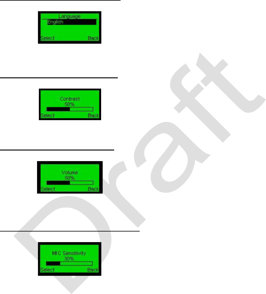
Settings - Accessibility - Language
Language Screen.
This screen allows you to
select the device interface language. For
this version it is English.
Settings – Accessibility - Contrast
Contrast Screen.
This screen allows you to
set the contrast of the display.
Select this option and set the contrast by
rotating the rotary switch.
Settings – Accessibility - Volume
Volume Screen.
This screen allows you to set
the volume of the speaker.
Select this option and set the volume by
rotating the rotary switch.
Settings – Accessibility - MIC Sensitivity
Microphone Sensitivity Screen.
This screen
allows you to set the sensitivity of the
microphone. Select this option and set the
volume by rotating the rotary switch.
Maximum recommended setting is 75%.

99-P42565K 53
SETTINGS - SAVE MODE
This option allows you to turn on the Screen Saver Mode of the unit in order to reduce
your battery power consumption.
Save Mode Option. In this mode, the
screen will be dimmed automatically after
13 seconds if during this period no keys
(Keypad keys, Rotary button, Panic button,
and Push button) are pressed.
The screen will turn back on after you
press any key.
When turned on, the Save Mode option
will display on
, when turned off, it will
display off
. To turn the mode on or off,
select it in the Settings screen.
SETTINGS - DARK MODE
This option allows you to turn the Dark operation Mode of the unit on or off. To do so,
select it in the Settings screen.
Dark Mode Option. When turned on, the Dark
Mode option will display on, the screen will be
dimmed, and the LED indicating incoming and
outgoing calls will be turned off.
When turned off, the Dark Mode option
will display off, and the screen brightness
will follow the settings of the Save Mode.
SETTINGS - VOICE FB
This menu option enables voice feedback indicating when the channel is changed.
Voice FB Screen. Set the menu option to on or
OFF as applicable.

54 99-P42565K
SETTINGS - ALERT TONES
You can activate various audible alert tones listed on this screen.
Alert Tones Screen. Press the left function key
to set the option to on to enable the alert.
• Busy – when the called party is busy.
Alerts the sender when the sender makes
a private call to the called radio and the
called party is already in a call.
• Out of service – when your device is out
of service.
• Net Join –
when your unit joins the
network.
• SMS – set to on to enable reception of
text (SMS –
Short Message Service)
messages.
• Power Up – when the unit is turned on.
• Power Off – when the unit is turned off.
• Volume –
when on you can listen to
changes each time the volume control
button is turned to the left or right.
• Low Battery – when on, you are alerted
if the battery charge level becomes low.
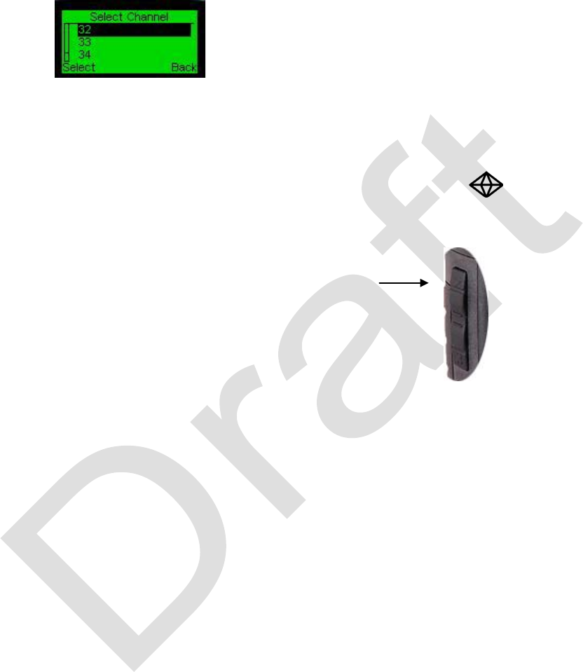
99-P42565K 55
SETTINGS – SELECT CHANNEL
This screen is used in selecting a unique radio channel.
Channel Selection Screen. Pathmaker
system can operate on 40 different
channels. You can select any channel
from 1 to 40. You can use the scrolling
keys or the volume control to select the
desired channel.
In order to set up a network, all units must
transmit on the same channel.
The Push switch ( )
serves as a
shortcut key to this screen from the Main
menu screen.
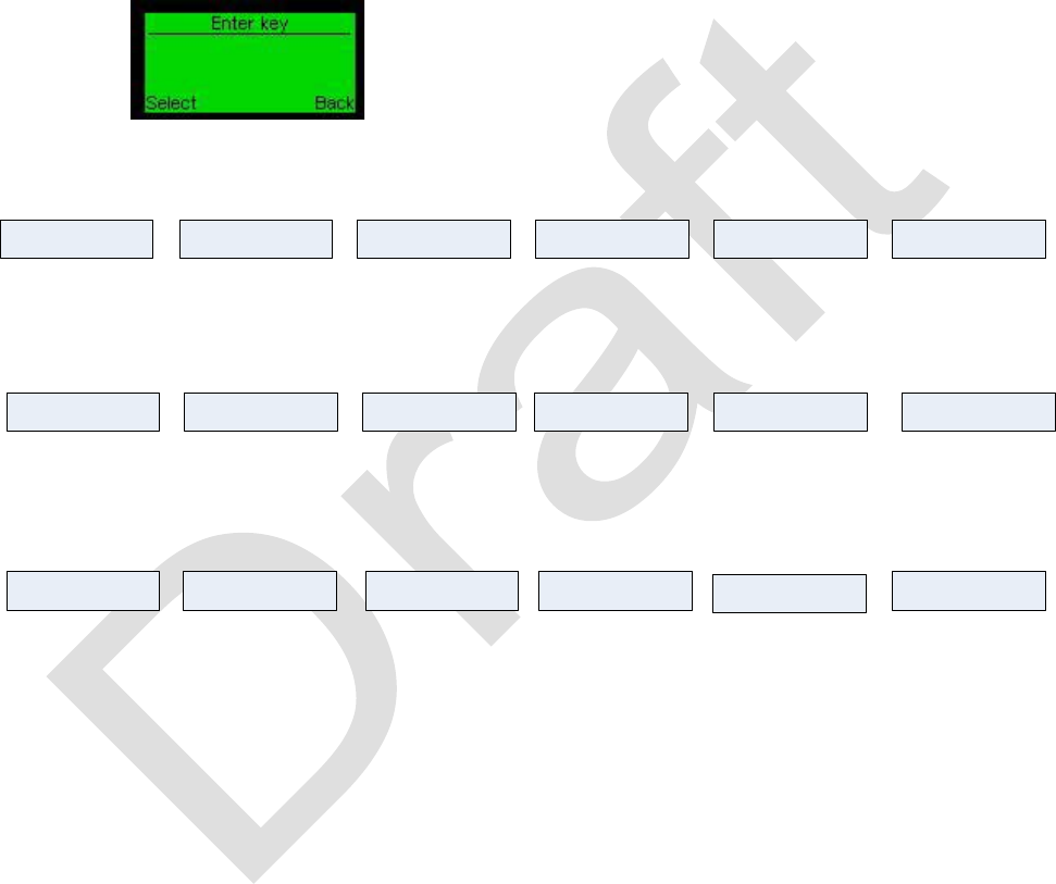
56 99-P42565K
SETTINGS - TECHNICIAN
This screen is used for internal system administrator settings, network complex
calibration settings, etc. This screen is password protected. When the screen displays,
enter your password within 30 seconds and then press Select.
Technician password enter screen.
The menu options are listed in the following figure and table.
Select channel
• Channel Screen
Edit Groups
• Groups List
Remote Update
• Receive Update
• Transmit Update
Master Reset
• Confirmation
BER Meter
• Transmit
• Receive
• Transmit FEC
• Receive FEC
Listen Mode on/off
Key Locked on/off Drop Down on/off Emergency on/off PTT auto/on/off Crypt
Commander on/off GW Sound on/off Matrix Setup Debug Level Compilation Date About
Show ID on/off
• Crypt Key
• Crypt Data on/off
• Crypt Voice on/off
• Crypt Statistics
• Matrix On/Off
• RSSI On/Off
• None
• Debug
• Errors
• Warnings
• Info
• All
Figure 9 - Technician Menu Map

99-P42565K 57
TECHNICIAN SUB-MENU OPTIONS
1st Level
2nd Level
Function
Select
Channel
1 to 40
channel range
Select channel from list
Edit Group *
List of groups
Select group name to
edit
Remote
Update**
Receive
Update
Transmit
Update
Set all units to be
updated to Receive
Update mode
Set one unit with
updated firmware to
Transmit Update mode
Master Reset
Reset the unit to default
parameters
BER
Meter***
Transmit
Receive
Transmit FEC
(Forward Error
Correction)
Receive FEC
Transmission without
FEC
Receive without FEC
Transmission with FEC
Receive with FEC
Listen Mode
ON/OFF ****
Off normal operation
On listen only to the
network
Key Locked
ON/OFF
Off normal operation
On the unit is
automatically locked
when turned on
Drop Down
ON/OFF *****
Off normal operation
On drop down station
Emergency
ON/OFF
Off no panic function
On panic enabled
PTT auto
ON/OFF
Auto PTT enabled only
if no headset
connected
Off no PTT at the unit
ON PTT enabled

58 99-P42565K
1st Level
2nd Level
Function
Crypt
Crypt Key
16 character alpha-
numeric key.
Crypt Data
ON/OFF
Enables or disables
data encryption.
Crypt voice
ON/OFF
Enables or disables
voice encryption.
Crypt Statistics
Displays encrypted
Voice and data packets
sent & received in unit.
Show ID
ON/OFF
Off - ID of the unit not
displayed on main
screen.
On - ID displayed on
main screen.
Commander
ON/OFF
Off - Normal operation
On - Prioritized mode
enabled.
GW Sound
ON/OFF
Off no sound.
On sound enabled.
Activate only on Bridge
Unit connected to
gateway.
Matrix Setup
Matrix ON/OFF
Display of the Matrix
ON/OFF
RSSI ON/OFF
Display RF reception
parameters of the units
received.
Debug level
None
Set level of the debug
tool
No printout
Errors
Error messages only
Warnings
Warning and error
messages only
Info
Info warning and error
messages only
All
All messages

99-P42565K 59
1st Level
2nd Level
Function
Compilation
Date
Displays date of
compilation
About
HID
NID
SW
HW
Hard ID of the unit
Network ID of the
network
Software version
Hardware version
Notes:
* Edit group should be executed on all units related to the operating network.
** The minimal distance between transmit and receive unit should be 1.5 meters.
Transmit unit must be in line of sight with the receive units. All units must be on the
same channel.
*** BER (bit error rate) tests the quality of RF reception between two units. Test can be
executed with FEC (Forward Error Correction) or without. Both units have to be on the
same channel and on the same mode (FEC / no FEC).
**** Unit in listen mode receives information from directly received units depending on
network condition.
***** When this function is activated, the display and LEDs dim, keyboard locks and
volume mutes. (In this mode the unit serves usually as a relay station).
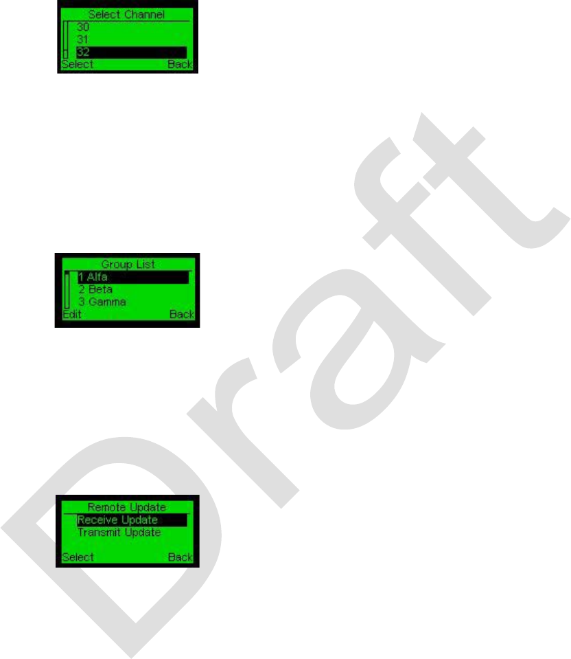
60 99-P42565K
TECHNICIAN - SELECT CHANNEL
All radios must be on the same channel to communicate.
Channels are numbered from 1 to 40.
Select the appropriate channel and press
Select. The number of the selected
channel will be displayed on the main
menu.
TECHNICIAN - EDIT GROUP
This screen displays the list of group names which can be edited further.
Group names must match in order for the
radios to communicate in a group. If a
given group name is changed in one radio,
the name of the same group has to be
changed in all units related to same
network.
TECHNICIAN - REMOTE UPDATE
This screen is used to update the firmware version.
Select a separate channel for all units to
be updated.
On units to be updated, select Receive
Update and then press Select.
Select an updated unit with the relevant
firmware version, set it to Transmit
Update and then press Select.
There
should be a minimum distance of
1.5 meters between the transmit unit and
the receive units. Verify that line of sight
exists between transmitting unit and
receiving units.
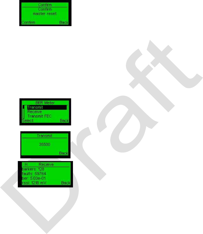
99-P42565K 61
TECHNICIAN - MASTER RESET
This screen is used to reset the unit to its default parameters.
Press Confirm to endorse the reset
operation of the unit to its default version
parameters.
TECHNICIAN - BER METER
This screen is used to check the quality of RF reception without correction or in FEC
mode with correction.
To initiate the BER (Bit Error Rate) test,
set one unit to Transmit mode and the
other unit to Receive mode.
Select Transmit to view the transmit Baud
rate.
The test results are displayed on the
receiver unit.
To initiate the FEC (Forward Error
Correction) test, set one unit to Transmit
mode and the other unit to Receive mode.
Note:
Verify that both units are on the same
channel and mode (with or without FEC).
TECHNICIAN - LISTEN MODE ON/OFF
The unit in Listen mode cannot transmit and does not relate to the network structure. It
will not be displayed on the MATRIX of the units in the network.

62 99-P42565K
Unit in Listen mode receives information only from directly received units depending on
network condition.
This menu option functions like a rotary switch.
OFF – unit operates in normal mode.
ON – the unit can listen only.
TECHNICIAN - KEY LOCKED ON/OFF
This menu option functions like a rotary switch.
OFF – the keyboard is not locked.
ON – the keyboard is locked
TECHNICIAN - DROP DOWN ON/OFF
This menu option functions like a rotary switch.
OFF – The unit operates normally.
ON – T
he unit functions as a relay station
and the keyboard locks.
TECHNICIAN - EMERGENCY ON/OFF
This menu option functions like a rotary switch.
OFF – panic function disabled
ON – panic function enabled
TECHNICIAN - PTT – AUTO/ON/OFF
This menu option functions like a rotary switch.
Auto – push-to-talk enabled only if no headset is connected
OFF - push-to-talk disabled
ON - push-to-talk enabled
TECHNICIAN – CRYPT (ENCRYPTION)
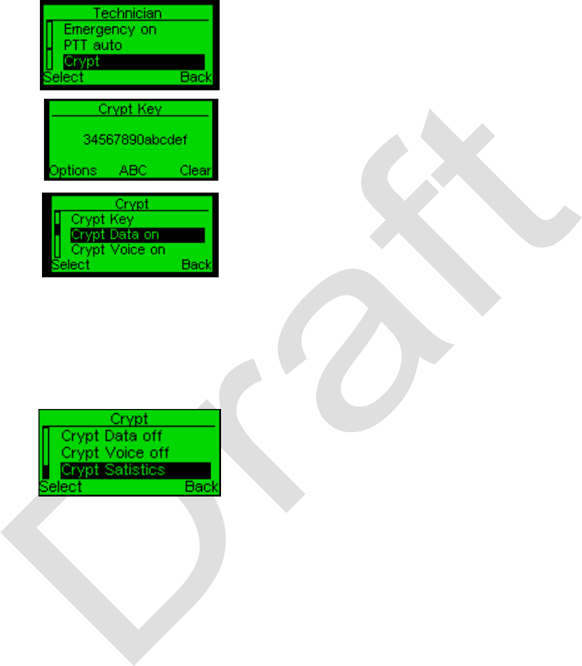
99-P42565K 63
These screens are used enable & configure encryption of voice or data transmitted in
the network.
Select Crypt to enter encryption settings.
Crypt Key – 16 characters key -Used for
all encryption ( Voice & data) – must be
the same for all network.
Crypt data OFF – Transmitted Data is not
encrypted.
Crypt data ON – – Transmitted Data is
encrypted.
Crypt Voice OFF – Transmitted Voice is
not encrypted.
Crypt Voice ON – Transmitted Voice is
encrypted.
Displays encrypted voice and data packets
sent & received in unit.
E-D – Encrypted data.
E-V - Encrypted voice.
D-D - Decrypted data.
D-V - Decrypted voice.
TECHNICIAN - SHOW ID ON/OFF
Unit ID is determined by the order in which a radio enters the network.
This menu option functions like a rotary switch.
OFF – Unit ID is not displayed on the main menu.
ON - unit ID is displayed on the main menu
TECHNICIAN - COMMANDER ON/OFF

64 99-P42565K
This function must be set to on to enable the Prioritize function in the talk menu. This
menu option functions like a rotary switch.
OFF – Normal operation
ON – The radio’s transmissions take priority over any others in the network.
TECHNICIAN - GW SOUND ON/OFF
This menu option functions like a rotary switch.
When the radio operates as a bridge unit,
the sound can be turned off.
OFF – sound is disabled
ON – sound is enabled
TECHNICIAN - MATRIX SETUP
You can select the following options:
•
Matrix (Displays units and their
functionality in the network)
•
RSSI (Displays receive signal
parameters)
When Matrix is set on, letters in the boxes display the functionality of the units as listed
in the Matrix Code below.
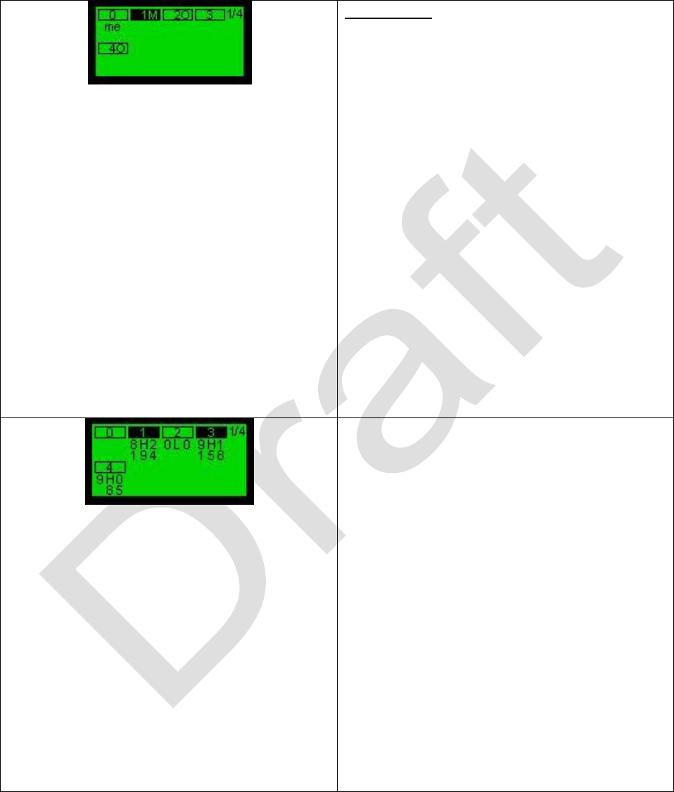
99-P42565K 65
Matrix code
R – relay station
O – the unit contacts you via the relay
station (you do not see the unit directly)
M – main relay station (best connected
relay node)
L – transmission from this unit is received
but is below the required reception level
and consequently cannot be part of the
network
N – transmission from this unit is received
but it cannot be part of the network due to
limitations of the network.
Note:
Units displayed by an empty box indicates
that the unit functions normally (not as a
relay) and receives transmissions directly.
When RSSI is set on, the receive signal
parameters are displayed.
The top left digits represent the number of
packets directly received from a possible
last 9 packets window. The top right digit
represents the quality of the link used to
communicate: 3 is the best, 0 is no link.
The character in the middle (L or H)
represents the state of the low noise
amplifier. H - the amplifier is operational, L
- the amplifier is not running, in order to
avoid signal compression when the units
are close to each other.
The lower digits show the Received Signal
Strength value (0 - 750 possible) of the
signal received from this unit.
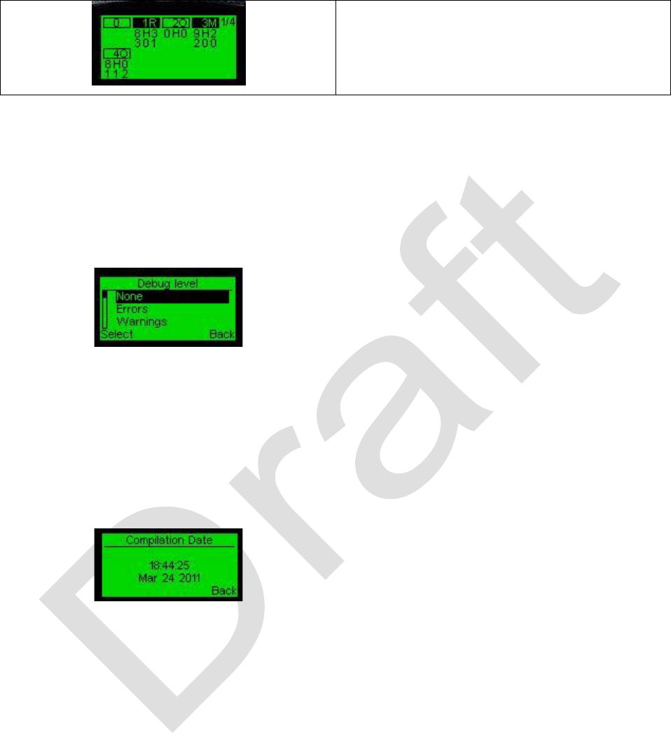
66 99-P42565K
In this view both Matrix and RSSI are On.
To view complete network picture both
Matrix and RSSI should be on.
TECHNICIAN - DEBUG LEVEL
This menu options enable setting the level of the debug operation.
Select one of the following options:
None – no debug
Errors – show errors only
Warnings – show warnings only
Info – show information only
All – show all of the above
TECHNICIAN - COMPILATION DATE
This menu option shows the date of the
last compilation.

99-P42565K 67
TECHNICIAN - ABOUT
This screen shows firmware versions.
HID (Hardware ID) is the unique unit
identification number.
NID (Network ID) is the unique unit
identification number.*
SW is the software version of the unit.
HW is the hardware version of the unit.
•
The radio can operate with devices
of the same NID.

68 99-P42565K
LOCK/UNLOCKING THE KEYPAD
To Lock/Unlock the keypad, press “*” and then “#”.
When the keys are locked, the PTT button
remains active.

99-P42565K 69
MAINTENANCE
The maintenance concept for the Pathmaker radio consists of removal and replacement
of faulty parts such as the antenna, battery, belt clip, earphone, or USB cable at the
organizational level. The radio has no serviceable parts. Do not disassemble the device.
Radios requiring repair must be returned to General Dynamics for repair.
The Pathmaker radio assembly kit, part number 01-P42559K001 consists of the
following replaceable parts:
Table 8 - Replaceable Parts
Description
Part Number
Assembly, Pathmaker Radio
01-P42558K001
Antenna, 2dB 2.4GHz Omni Direction
85-P42580K001
Battery, Pathmaker
60-P42581K001
Belt Clip, Pathmaker
42-P42582K001
User Documentation, Pathmaker Network Radio
99-P42565K
Preventive Maintenance
Preventive maintenance consists of inspection of the radio’s surfaces, contacts, and
connectors for damage or contaminants.
Clean the unit’s exterior using a clean, lint-free cloth moistened in a solution of mild
household detergent and water. Follow this by wiping down with a clean, lint-free cloth
moistened in clean water, and then wipe dry. Never use harsh detergents, chemical
cleaning agents, abrasive compounds, or bristle brushes to clean the unit.
Preventive maintenance also includes charging the battery to ensure it retains a charge.

70 99-P42565K
Corrective Maintenance
Corrective maintenance consists of observing a symptom, determining probable cause,
and then taking corrective action. The table below can be used as a troubleshooting
guide to correct common problems.
Troubleshooting Guide
Symptom
Probable Cause
Corrective Action
Radio will not power up.
Dead or low battery.
Replace or recharge battery.
Defective radio.
Replace radio.
Cannot receive from any other
radios in network.
Volume setting too low.
Adjust volume.
Incorrect channel setting.
Set to proper channel.
Out of range.
Check Matrix view. Position
radio in range with another
radio in network.
Defective radio.
Replace radio.
Can send/receive messages
by only one radio in network.
Radio is in Private mode.
Set radio to Broadcast or
Group mode.
Can send messages to some
radios in network but not all.
Radio is in Group mode.
Set radio to Broadcast mode.
Radio drops out of network.
Out of range.
Check Matrix view for other
radios. If none are present,
position radio in range with
another radio in network. If
other radios are present, radio
may be defective.
Defective radio.
Replace radio.
Voice is not heard in distant
unit.
Transmitting unit “mic
sensitively” =0
Change “mic sensitively”>0
(menusettingAccessibilt
mic sensitivity
Receiving unit is in mute
Change volume level in
receiving unit
Talk mode is not defined
correctly (private, group etc. )
Change talk mode
RF connectivity problem
Check if Antenna icon exists.,
Check matrix status and verify
Line of Sight between every 2
units
Defective battery.
Replace battery.
PTT is disabled.
Technician > PTT
ON/OFF/Auto
Defective PTT
Replace radio
Listen Mode is enabled.
An “L” is displayed near upper
right corner of main screen.
Technician > Listen Mode
ON/OFF

99-P42565K 71
Symptom
Probable Cause
Corrective Action
Can’t see unit ID on main
screen.
Unit ID turned off.
Technician > Show ID
ON/OFF
Power Button will not turn
radio off.
Keypad is locked. “Locked” is
displayed in lower left of
screen.
Press * then # to unlock or
lock.
Technician > Key Locked
ON/OFF
Cant see GPS coordinates
GPs is not enabled.
Settings > GPS Setup Set
GPS ON/OFF
Can’t find Prioritize mode in
Talk screen
Commander is off.
Technician > Commander ON
Panic button doesn’t work
Emergency mode is off
Technician > Emergency
ON/OFF
None of the keypad keys
work.
Keypad is locked.
Press * then # to unlock or
lock.
Battery does not charge.
Charger LED green.
Defective charger.
Replace charger
Battery does not charge.
Charger LED red.
Defective battery.
Replace battery.
Battery does not charge.
Charger LED blinking red.
Defective charger.
Replace charger.
Battery does not charge.
Charger LED amber.
Battery not seated properly.
Reseat battery.

72 99-P42565K
Repair Parts
Description
Part Number
Antenna, 2dB 2.4GHz Omni Direction
85-P42580K001
Battery, Pathmaker
60-P42581K001
Belt Clip, Pathmaker
42-P42582K001
Assembly, Pathmaker Radio
01-P42558K001
Cable, Pathmaker USB Data
30-P42577K001
User Documentation, Pathmaker Network Radio
99-P42565K
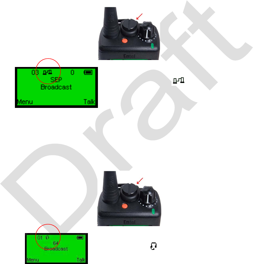
99-P42565K 73
ACCESSORIES
USB/RS-232 Communication Cable
The communication cable is used to interface with various digital devices (PC,
Gateways etc.).
The serial cable communication connection is illustrated below.
When the cable is used to attach the unit
to a PC, the icon is displayed on the
Main screen indicating the cable
connection.
Headset
The Headset kit is connected to the accessory connector of the unit as follows:
When the Headset is attached, a Headset
icon will appear on the Main screen
indicating connection.
As long as the connection exists, all the
incoming and outgoing sessions will be
conducted by means of the Headset.
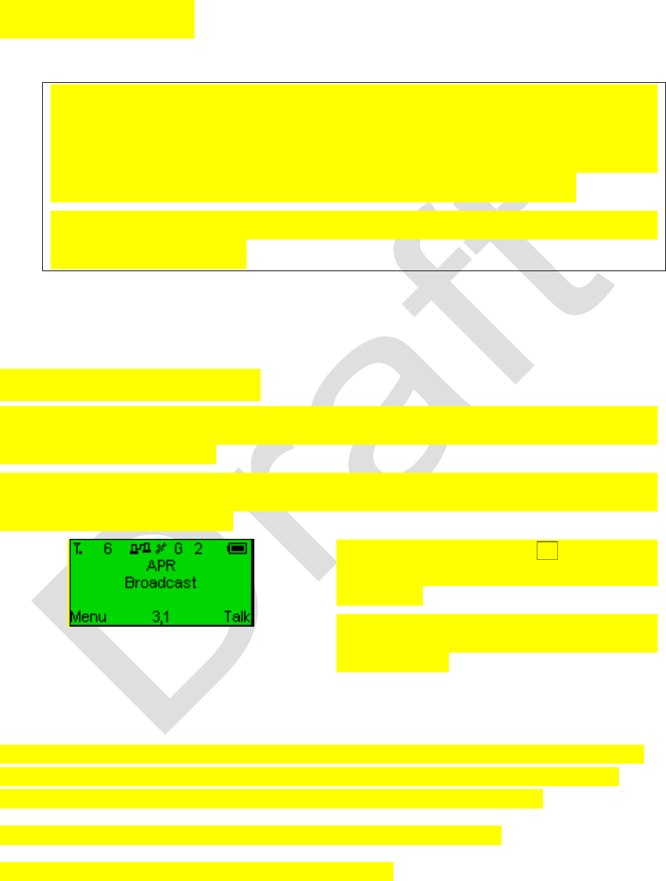
74 99-P42565K
GATEWAYS
Gateways are optional and are documented separately. Please refer to the
documentation supplied with the gateway for setup and system integration
information. The following section applies only after the integration process has
been completed and the radio has established contact with a gateway.
Many of the screens shown below are not be available unless the radio has been
integrated with a gateway.
Gateway - GSM GW
This mode enables you to send and receive conventional telephone calls using the
radios. Any radio in the network can place a call t by dialing the desired telephone
number by using the keypad.
Similarly, any conventional telephone is able to place a call directly to any radio in the
network. To do so, callers must know the telephone number of the GSM Gateway and
the Unit ID of the desired radio.
The GSM Gateway icon
G
displays on
the Main screen upon making the
connection.
The radio’s network ID number is shown to
the right of the Gateway icon. In this
example it is 2.
When in a GSM gateway configuration, you can place a call from a radio by dialing the
called party’s phone number as you would from a conventional telephone. After the
number is dialed, press and release the P2 shortcut key to place the call.
To answer an incoming call, press and release the P1 shortcut key.
To end a call, press and release the P3 shortcut key.

99-P42565K 75
When in a call, use the PPT key just as you would when using the radio in the voice
mode. That is, push to talk and release to listen.
Callers from conventional telephones must dial the GSM Gateway’s telephone number.
Upon connection, callers will be prompted to also enter the target radio’s Unit ID
number.
Gateway - Analog GateWay
In this mode you can use the gateway to communicate with other devices. Radios
connect to the Analog Gateway over-the-air.
The Multi-GW unit defines which units in the Pathmaker network will receive the analog
network session and defines which Pathmaker network sessions will be transmitted to
the analog network.
• When the [A] icon is present on the general screen of the unit, in “Talk” mode of the
unit will appear additional talk mode “Analog GW”.
• Use regular broadcast call in order to perform a voice call to the analog network.
• Management of the Multi GW unit can be done from the Pathmaker Suite application
remotely.
• Only one session to/from analog network can be done at a time.
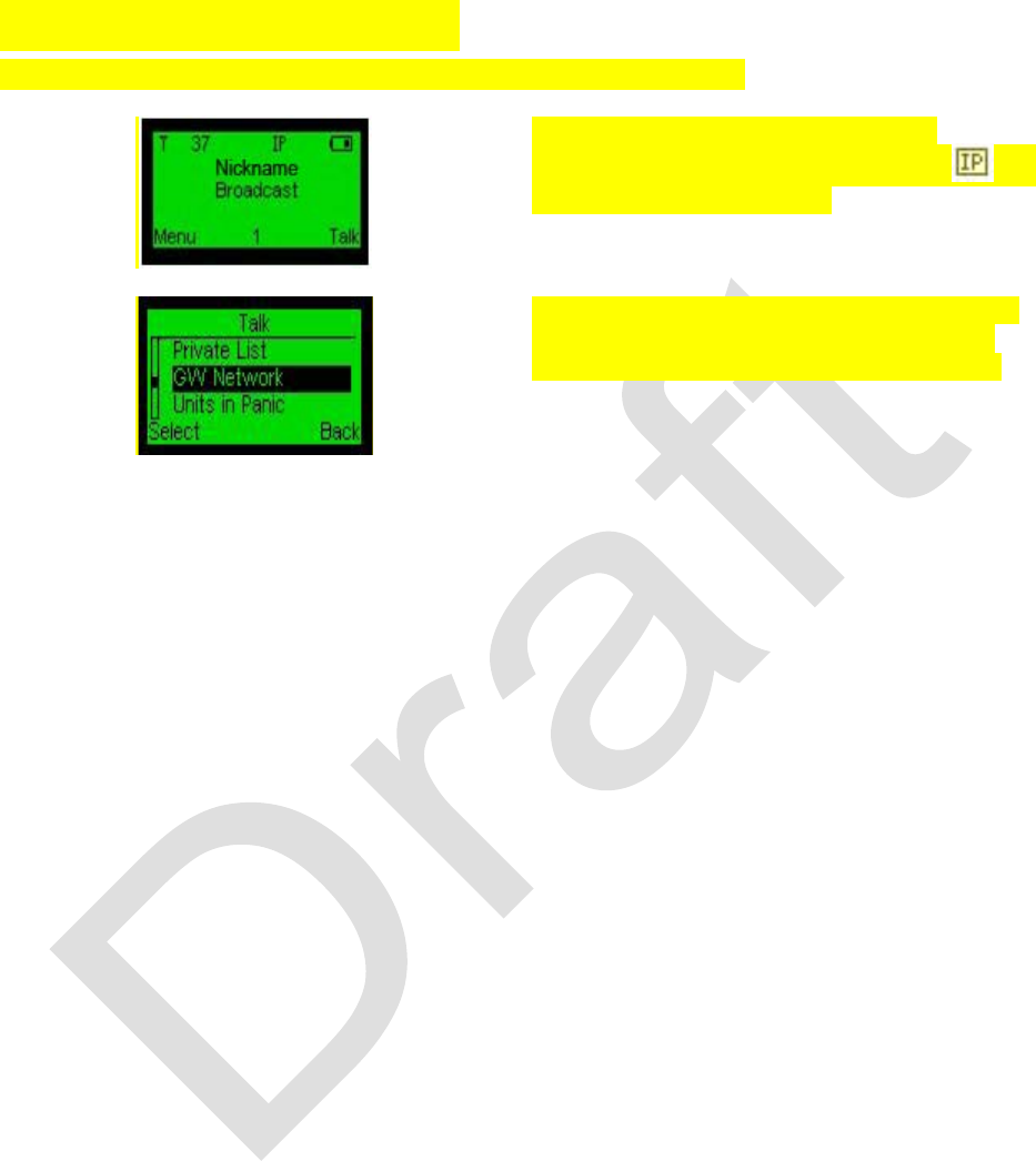
76 99-P42565K
Gateway - IP Gateway
Enables the connection between different networks via TCP/IP.
The connection will be acknowledged
automatically and the IP gateway icon will
display on the Main screen.
To view your IP Networks list, select the GW
Network option in the Talk Modes screen.
Afterwards, connect to one of the networks.

99-P42565K 77
ACRONYMS AND ABBREVIATIONS
Acronyms and Abbreviations
BER
Bit Error Rate
CDMA
Code Division Multiple Access
EMI
Electro-magnetic Interference
FB
Feedback
FEC
Forward Error Correction
FSK
Frequency-shift keying
GPS
Global Positioning System
GPRS
General packet radio service
GSM
Global system for mobile communications
GW
Gateway
HW
Hardware
IEC
International Electrotechnical Commission
LED
Light emitting diode
LCD
Liquid Crystal Display
MIL-STD
Military Standard
PC
Personal computer
PDA
Personal digital assistant
PSTN
Public Switched Telephone Network
PMR
Private mobile radio
PTT
Push-to-talk
RF
Radio frequency
RSSI
Receive Signal Strength Indication
SATCOM
Satellite Communications
SMS
Short Message Service. Text messages.
SW
Software
Tetra
Terrestrial trunked radio
TCP/IP
Transmission control protocol/Internet protocol
TX
Transmit
UHF
Ultra high frequency
VHF
Very high frequency
WiFi
Wireless Fidelity
WiMax
Worldwide Interoperability for Microwave Access