General Dynamics Itronix GD3000 TABLET PC User Manual
General Dynamics Itronix Corporation TABLET PC Users Manual
UserManual.wiki
>
General Dynamics Itronix
>
GD3000 User Manual
Users Manual
Navigation menu
Upload a User Manual
Namespaces
Wiki Guide
HTML
PDF
Info
Views
User Manual
Discussion / Help
Navigation


![30 z Screen Rotation This MCA uses G sensor to switch Landscape/Portrait mode automatically when the machine turns. It works for 0º - 90º - 180º - 270º, and can be enabled/ disabled through the [Digiheal Application software]. Default setting is enabled.](https://usermanual.wiki/General-Dynamics-Itronix/GD3000/User-Guide-1307789-Page-34.png)
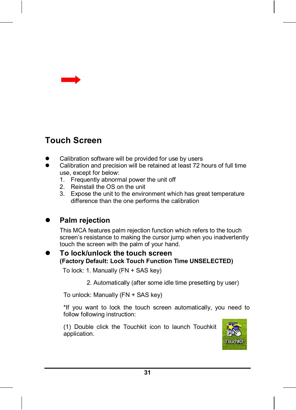
![32(2) Select [Setting] Æ [Option] (3) You will find [Lock Touch Function Time] section on the bottom. Select [Enable] to activate this function. You can also adjust the idle time in this section. Information about Fingerprint function With use of fingerprint authentication, you can log on to Windows by only authenticating fingerprints that have previously been registered.](https://usermanual.wiki/General-Dynamics-Itronix/GD3000/User-Guide-1307789-Page-36.png)


![41 Information about 3G function Note: The system does not support 3G Voice features. The system provides 3G function (optional), please remove the SIM card cover. Then insert 3G SIM card into the slot. Attention: WLAN function will be auto turn-off when 3G function is on. Please click on [3G Watcher] program shown on Desktop to turn on 3G function. Please follow 3G Watcher Help Topics/ Wireless Data Connections/Manage profiles to create a profile first. After all settings are completed, click Connect to access Internet. User will find on Windows task bar. The indicator shows the received signal strength in dBm up to a maximum of five](https://usermanual.wiki/General-Dynamics-Itronix/GD3000/User-Guide-1307789-Page-45.png)


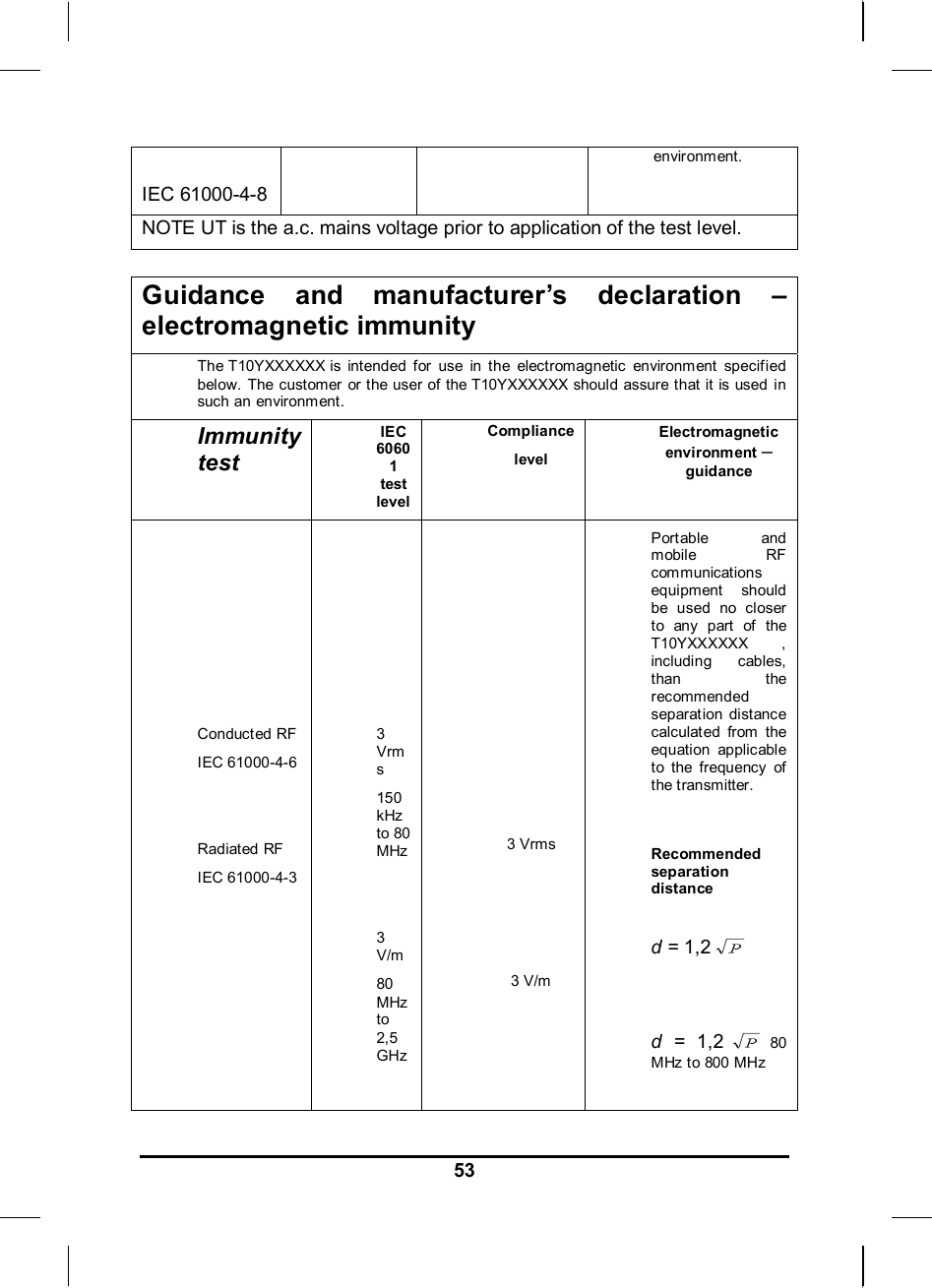
![52put lines Surge IEC 61000-4-5 ±1 kV line(s) to line(s) ±2 kV line(s) to earth ±1 kV line(s) to line(s) ±2 kV line(s) to earth Mains power quality should be that of a typic al commercial or hospital environment. interruptions and voltage variations on power supply input lines IEC 61000-4-11 <5 % UT (>95 % dip in UT) for 0,5 cycle 40 % UT (60 % dip in UT) for 5 cycles 70 % UT (30 % dip in UT) for 25 cycles <5 % UT (>95 % dip in UT) for 5 sec <5 % UT (>95 % dip in UT) for 0,5 cycle 40 % UT (60 % dip in UT) for 5 cycles 70 % UT (30 % dip in UT) for 25 cycles <5 % UT (>95 % dip in UT) for 5 sec Mains power quality should be that of a typic al commercial or hospital environment. If the user of the T10YXXXXXX ] requires continued operation during power mains interruptions, it is recommended that the T10YXXXXXX be powered from an uninterruptible power supply or a battery. Power frequency (50/60 Hz) magnetic field 3 A/m 3 A/m Power frequency magnetic fields should be at levels characteristic of a typical location in a typical commercial or hospital](https://usermanual.wiki/General-Dynamics-Itronix/GD3000/User-Guide-1307789-Page-64.png)