General Dynamics Itronix IX100XUSI-WLBT 802.11bg WLAN Module User Manual WM BG MR 01 25 041406
General Dynamics Itronix Corporation 802.11bg WLAN Module WM BG MR 01 25 041406
Contents
- 1. USERS MANUAL
- 2. users manual
- 3. integrator manual
integrator manual

All rights are reserved by USI. No part of this technical document can be reproduced in any form without permission of USI
. 1
Data Sheet
of 802.11g
WM-BG-MR -01 B2B Wireless Lan +BT Combo Module
Data Sheet A
pr
14th. 2006 Rev 2.5
802.11g Wireless LAN SiP Module
(
WM-BG-MR -01
)
www.usi.com.tw
802.11g Wireless LAN+BT SiP combo Module V2.2
All rights are reserved by USI. No part of this technical document can be reproduced in any form without permission of USI
. 2
Introduction
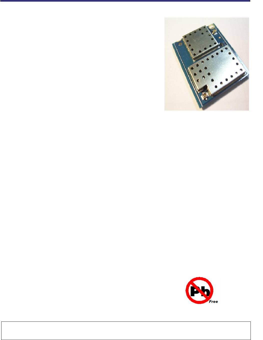
The 802.11 Wireless SiP module WM-BG-MR-01
which refers as “SiP-g combo module” is a small
size module that provides full function of 802.11g/b
and Bluetooth class 2 on a tiny module via 60 pins
board to board connector.
This multi- functionality and board to board physical
interface provides 16 bit PC Card /CF+ bus interface
for WiFi and UART for Bluetooth.
The small size & low profile physical design make it
easier for system design to enable high performance
wireless connectivity without space constrain. The
low power consumption (Sleep mode 1.2 mA) and
excellent radio performance make it the best
solution for OEM customers who require embedded
802.11g Wi-Fi + Bluetooth features, such as,
Wireless PDA, Scanner Smart phone, Media player
slim type Notebook, barcode ,mini-Printer, VoIP
phone etc.
For 802.11g feature, Marvell “Libertas” chipset
solution is adopted and CSR BlueCore 03-ROM for
Bluetooth. The Radio architecture & high integration
MAC/BB chip provide excellent sensitivity with rich
system performance. Two antenna connectors
provide antenna connectivity for each function.
WM-BG-MR-01 provides outstanding BT WiFi co-
existence solution through internal 2 wires ,
hardware interface to optimized connection with
CSR Bluetooth solution even without good antenna
isolation between BT & WiFi module.
In addition to WEP 64/128, WPA and TKIP, AES is
supported to provide the latest security requirement
on your network.
For the software and driver development, USI
provides extensive technical document and
reference software code for the system integration
under the agreement of Marvell International Ltd.
Features
z Lead Free design which supporting Green
design requirement, RoHS Compliance.
z 2 wires, hardware signaling BT WiFi co-
existence supported.
z Small size suitable for low volume system
integration.PCM audio interface
supported.
z Low power consumption & excellent
power management performance, extend
battery life.
z 2.412-2.484 GHz two SKUs for worldwide
market.
z Easy for integration into mobile and
handheld device with flexible system
configuration and antenna design.

802.11g Wireless LAN+BT SiP combo Module V2.2
All rights are reserved by USI. No part of this technical document can be reproduced in any form without permission of USI
. 3
Change Sheet
Rev.
Date
Description of change
Approval & Date
Page Par Change(s)
1.0 10/1/04 All All Draft version for Review
2.0 04/11/05 6,15,
17,22
,23,
25~2
7
1. Executive summary for target available
date from “the middle of 1Q 2005” to
“ the end of 2Q”
2. Output power for 11g is 13 +/- 1dBm
3. Update the mech. Drawing .
4. Modify the function description for
Marvell Transceiver from ”8010” to
“8015”
5. Correct the Pin Definition for xxx_B is
for “active_high”
6. add description for Pin 28;36;43;58 ;
which reserved for BT’s PCM interface ,
make it no confuse in customer reading.
2.1 04/18/05 25 1. correct the pin definition for Pin24 from
“Control signal to enable engineer testing
mode “ to “Output signal to indicate 16 bit IO
operation. This signal is connected to ground at module
side to indicate 16 bit IO..” then Type is for GND to
indicate the module under the mode for 16bit IO.
2.2 04/28/05 24 1. Pin A10 pin definition change from “ the pin
is open to “This address range is mainly used
for accessing the CIS in Memory Mode. Signal
HA0 is not used in word access mode.” , Type
change from “ No connection” to “Input ,
PD,5VT”
2.3 10/31/05 2, 8,
9 Power Consumption
2.4 11/08/05 25,26
, 27 Add SDIO Pin Definition
2.5 04/14/06 17, all 1. Specify connectors for BT and WiFi
2. Add page numbers

802.11g Wireless LAN+BT SiP combo Module V2.2
All rights are reserved by USI. No part of this technical document can be reproduced in any form without permission of USI
. 4
TABLE OF CONTENTS
1. EXECUTIVE SUMMARY................................................................................................................6
2. DELIVERABLES .............................................................................................................................6
3. REFERENCE DOCUMENTS.........................................................................................................7
4. TECHNICAL SPECIFICATION .....................................................................................................8
4.1. ABSOLUTE MAXIMUM RATING ............................................................................................... 8
4.2. RECOMMENDABLE OPERATION CONDITION ......................................................................8
4.2.1. TEMPERATURE, HUMIDITY............................................................................................. 8
4.2.1. VOLTAGE AND CURRENT ............................................................................................... 8
BLUETOOTH...................................................................................................................................... 8
4.3. COMPACTFLASH SPECIFICATION......................................................................................... 9
4.3.1. DC ELECTRICALS.............................................................................................................9
4.3.2. AC ELECTRICALS ............................................................................................................. 9
4.3.3. COMPACTFLASH PROTOCAL TIMING ......................................................................... 10
4.4. WIRELESS SPECIFICATIONS................................................................................................14
4.5. RADIO SPECIFICATIONS 802.11G ........................................................................................ 15
4.6. RADIO SPECIFICATIONS 802.15 BLUETOOTH ................................................................... 15
4.7. BLUETOOTH RADIO CHARACTERISTICS............................................................................16
4.8. DIMENSIONS, WEIGHT AND MOUNTING.............................................................................17
4.8.1. DIMENSIONS ................................................................................................................... 17
4.8.2. WEIGHT............................................................................................................................ 17
4.8.3. MOUNTING ...................................................................................................................... 17
4.9. SHOCK AND VIBRATION........................................................................................................ 17
5. COMPATIBILITY AND INTEROPERABILITY ......................................................................... 18
5.1. WI-FI LOGO..................................................................................................................................
5.2. WHQL COMPLIANCE ..................................................................................................................
6. CONFIGURABILITY .....................................................................................................................19
7. OPERATING SYSTEM COMPATIBILITY.................................................................................20
8. LEGAL, REGULATORY & OTHER TECHNICAL CONSTRAINTS .....................................20
8.1. EMC .......................................................................................................................................... 20
8.2. PRODUCT SAFETY SPECIFICATION.................................................................................... 20
8.3. COMPONENT SPECIFICATION ............................................................................................. 20
8.4. RADIO REQUIREMENTS AND APPROVALS ........................................................................ 21
8.5. PRODUCT MARKING ..............................................................................................................22
8.6. ENVIRONMENTALLY SAFE MATERIAL RESTRICTIONS .................................................... 22
9. FUNCTIONAL DESCRIPTION................................................................................................23
9.1. HARDWARE............................................................................................................................. 23
9.2. HOST INTERFACE ..................................................................................................................24
9.2.1. LED INTERFACE .............................................................................................................27
9.2.2. ANTENNA INTERFACE................................................................................................... 28

802.11g Wireless LAN+BT SiP combo Module V2.2
All rights are reserved by USI. No part of this technical document can be reproduced in any form without permission of USI
. 5
9.2.3. BLUETOOTH INTERFACE .............................................................................................. 28
9.3. SOFTWARE.............................................................................................................................. 28
10. DESIGN FOR EXCELLENCE (DFX)...................................................................................... 28
10.1. TESTABILITY ........................................................................................................................... 28
10.2. LOGISTICS............................................................................................................................... 29
11. HUMAN FACTORS...................................................................................................................29
12. INDUSTRIAL DESIGN..............................................................................................................29
13. RELIABILITY.............................................................................................................................. 29
14. PACKAGE ..................................................................................................................................29

802.11g Wireless LAN+BT SiP combo Module V2.2
All rights are reserved by USI. No part of this technical document can be reproduced in any form without permission of USI
. 6
1. EXECUTIVE SUMMARY
The WM-BG-MR-01 module - is one of the product families in USI’s product offering, targeting for
system integration requiring a smaller form factor. It also provides the standard migration to high
data rate to USI’s current SIP customers. The WM-BG-MR-01 module providing B to B type
connector is provided as option for customers, who want to have Board to board type assembly.
This document outlines the product requirements for a “system in Package” 802.11g/(b) combo module –
here after referred as WM-BG-MR-01 Module.
This product is targeted for first shipments by end of 2Q 2005 and is designated for use in
embedded applications mainly in the mobile device, which required, small size and high data rate
wireless connectivity. The application such as, Wireless PDA, slim type Notebook, Media Adapter,
Barcode scanner, mini-Printer, VoIP phone, Data storage device could be the potential application
for wireless WM-BG-MR-01.
2. DELIVERABLES
The following products and software will be part of the product.
WM-BG-MR-01 Module with packaging
Evaluation kits, including application (CF, PCMCIA Adapter card, RF cable with SMA
connector, antenna),
Software utility which supporting customer for integration, performance test, and
homologation. Capable of testing, loading (firmware) and configuring (MAC, CIS) for the
WM-BG-MR-01 module.
Unit Test / Qualification report
Product Specifications.
Agency certification pre-test report base on adapter boards

802.11g Wireless LAN+BT SiP combo Module V2.2
All rights are reserved by USI. No part of this technical document can be reproduced in any form without permission of USI
. 7
3. REFERENCE DOCUMENTS
C.I.S.P.R.
Pub. 22 "Limits and methods of measurement of radio interference
characteristics of information technology equipment." International
Special Committee on Radio Interference (C.I.S.P.R.), Third Edition,
1997.
CB Bulletin
No. 96A "Adherence to IEC Standards: “Requirements for IEC 950, 2nd Edition
and Amendments 1 (1991), 2(1993), 3 (1995) and 4(1996). Product
Categories: Meas, Med, Off, Tron." IEC System for Conformity Testing
to Standards for Safety of Electrical Equipment (IECEE), April 2000.
CFR 47,
Part 15-B "Unintentional Radiators". Title 47 of the Code of Federal Regulations,
Part 15, FCC Rules, Radio Frequency Devices, Subpart B.
CFR 47,
Part 15-C "Intentional Radiators". Title 47 of the Code of Federal Regulations,
Part 15, FCC Rules, Subpart C. URL:
http://www.access.gpo.gov/nara/cfr/waisidx_98/47cfr15_98.html
CSA C22.2
No. 950-95 "Safety of Information Technology Equipment including Electrical
Business Equipment, Third Edition." Canadian Standards Association,
1995, including revised pages through July 1997.
EN 60 950 "Safety of Information Technology Equipment Including Electrical
Business Equipment." European Committee for Electrotechnical
Standardization (CENELEC), 1996, (IEC 950, Second Edition, including
Amendment 1, 2, 3 and 4).
IEC 950 "Safety of Information Technology Equipment Including Electrical
Business Equipment." European Committee for Electrotechnical
Standardization, Intentional Electrotechnical Commission. 1991, Second
Edition, including Amendments 1, 2, 3, and 4.
IEEE 802.11 “Wireless LAN Medium Access Control (MAC) And Physical Layer (PHY)
Specifications.” Institute of Electrical and Electronics Engineers. 1999.
802.11g Wireless LAN+BT SiP combo Module V2.2
All rights are reserved by USI. No part of this technical document can be reproduced in any form without permission of USI
. 8
4. TECHNICAL SPECIFICATION
The WM-BG-MR-01 is a B2B type assembly part, technical supporting, package
requirement needs to be taken into consideration.
4.1. ABSOLUTE MAXIMUM RATING
Supply Power Max +3.6 Volt
Non Operating Temperature - 40° to 85° Celsius
Voltage ripple +/- 2% Max. Values not exceeding Operating
voltage
4.2. RECOMMENDABLE OPERATION CONDITION
4.2.1. TEMPERATURE, HUMIDITY
The WM-BG-MR-01 module has to withstand the operational requirements as listed in the
table below.
Operating Temperature -20° to 60° Celsius
Humidity range Max 95% Non condensing, relative humidity
4.2.1. VOLTAGE AND CURRENT
Power supply for the WM-BG-MR-01 module will be provided by the host via the power pins
There will be separated power source for WiFi and Bluetooth.
802.11 g(b)
Voltage : VDD
Operating Voltage 3.3 Volt +- 10%
Current
Transmit 480 mA Typical @54Mbps, 12dbm
Receive 275 mA Typical@54Mbps, -70dbm
Deep Sleep 1.2mA Average
Inrush current 3000 mA Max.
The power consumption is standard related.
Bluetooth
Voltage : VDD
Operating Voltage 3.3 Volt +- 10%
802.11g Wireless LAN+BT SiP combo Module V2.2
All rights are reserved by USI. No part of this technical document can be reproduced in any form without permission of USI
. 9
Current
Transmit 50 mA Typical
Receive 40 mA Typical
Deep Sleep 100 uA Max
4.3. COMPACTFLASH SPECIFICATION
4.3.1. DC ELECTRICALS
The DC specification is under 3.3 voltage. Over full range of values specified in the “Recommended
Operation Condition” unless specified.
Power supply : VDD=3.3V
Symbol Parameter Condition Min Typ Max Units
VIH Input high voltage 0.5 VDD - VDD+0.5 V
VIL Input low voltage -0.5 - 0.35VDD V
VOH Output high voltage 2.4 - - V
VOL Output low voltage - - 0.4 V
4.3.2. AC ELECTRICALS
The DC specification is under 3.3 voltage. Over full range of values specified in the “Recommended
Operation Condition” unless specified.
Power supply : VDD = 3.3V
Symbol Parameter Condition Min Typ Max Units
IOH Input high voltage =0.7 VDD 11.3 - 32 mA
IOL Input low voltage =0.18VDD 10.5 - 38 mA
VOH Output high voltage 0.2VDD- 0.6VDD 2.4 0.518 4.0 V/ns
VOL Output low voltage 0.6VDD-0.2VDD - 0.592 4.0 V/ns
802.11g Wireless LAN+BT SiP combo Module V2.2
All rights are reserved by USI. No part of this technical document can be reproduced in any form without permission of USI
. 10
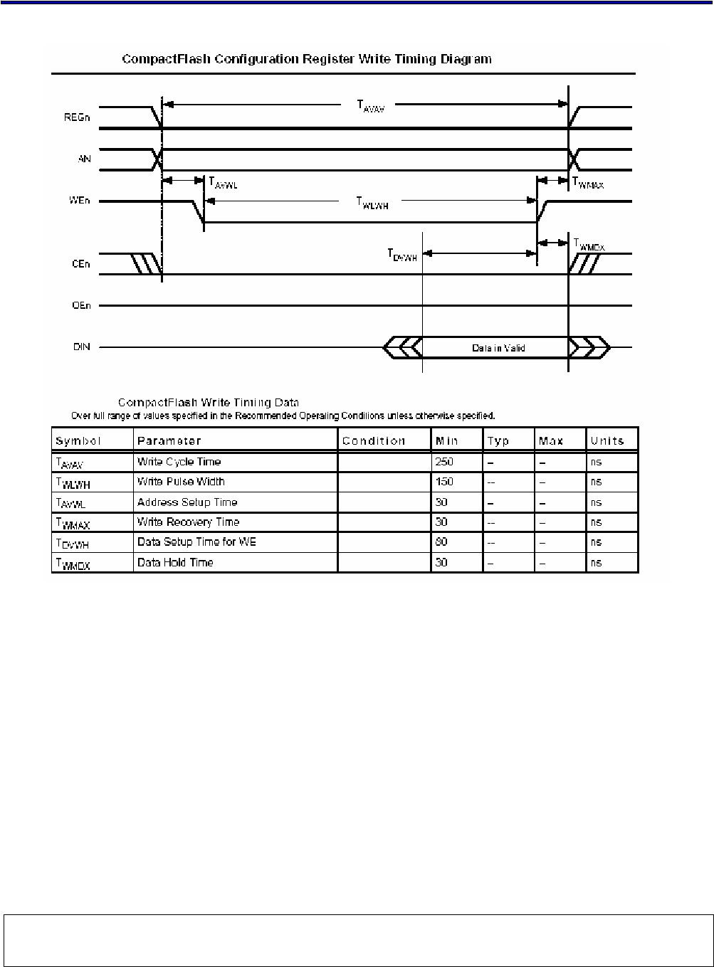
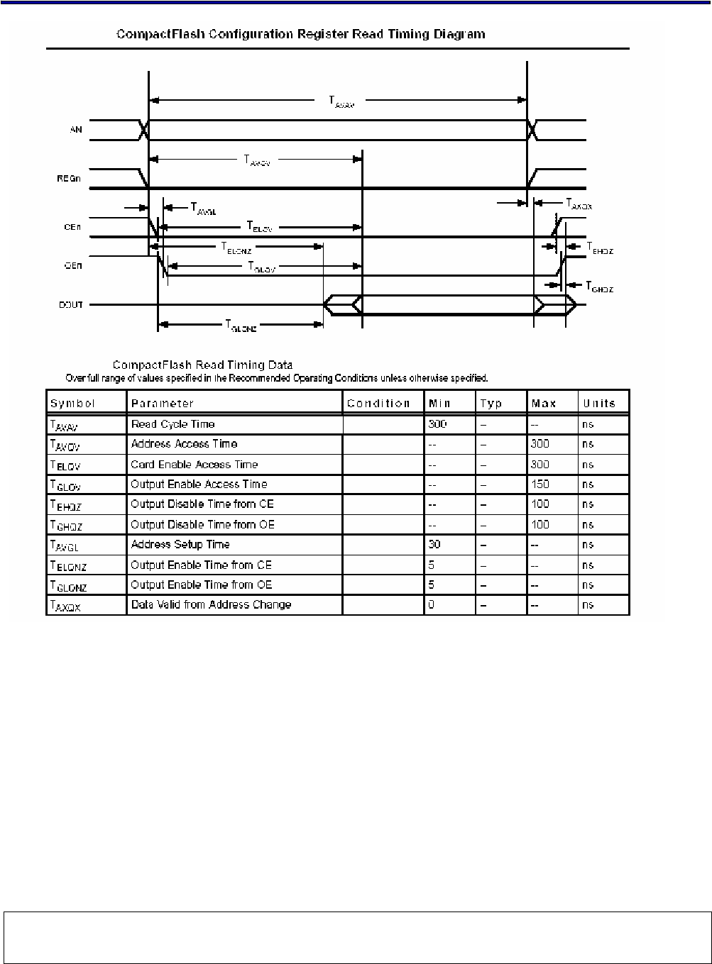
4.3.3. COMPACTFLASH PROTOCAL TIMING
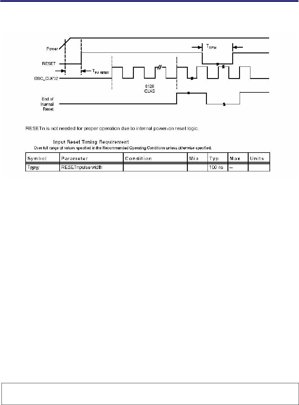
4.3.3.1. RESET SPECIFICATION
802.11g Wireless LAN+BT SiP combo Module V2.2
All rights are reserved by USI. No part of this technical document can be reproduced in any form without permission of USI
. 11
4.3.3.2. ATTRIBUTE MEMORY READ/WRITE TIMING SPECIFICATION
802.11g Wireless LAN+BT SiP combo Module V2.2
All rights are reserved by USI. No part of this technical document can be reproduced in any form without permission of USI
. 12
802.11g Wireless LAN+BT SiP combo Module V2.2
All rights are reserved by USI. No part of this technical document can be reproduced in any form without permission of USI
. 13
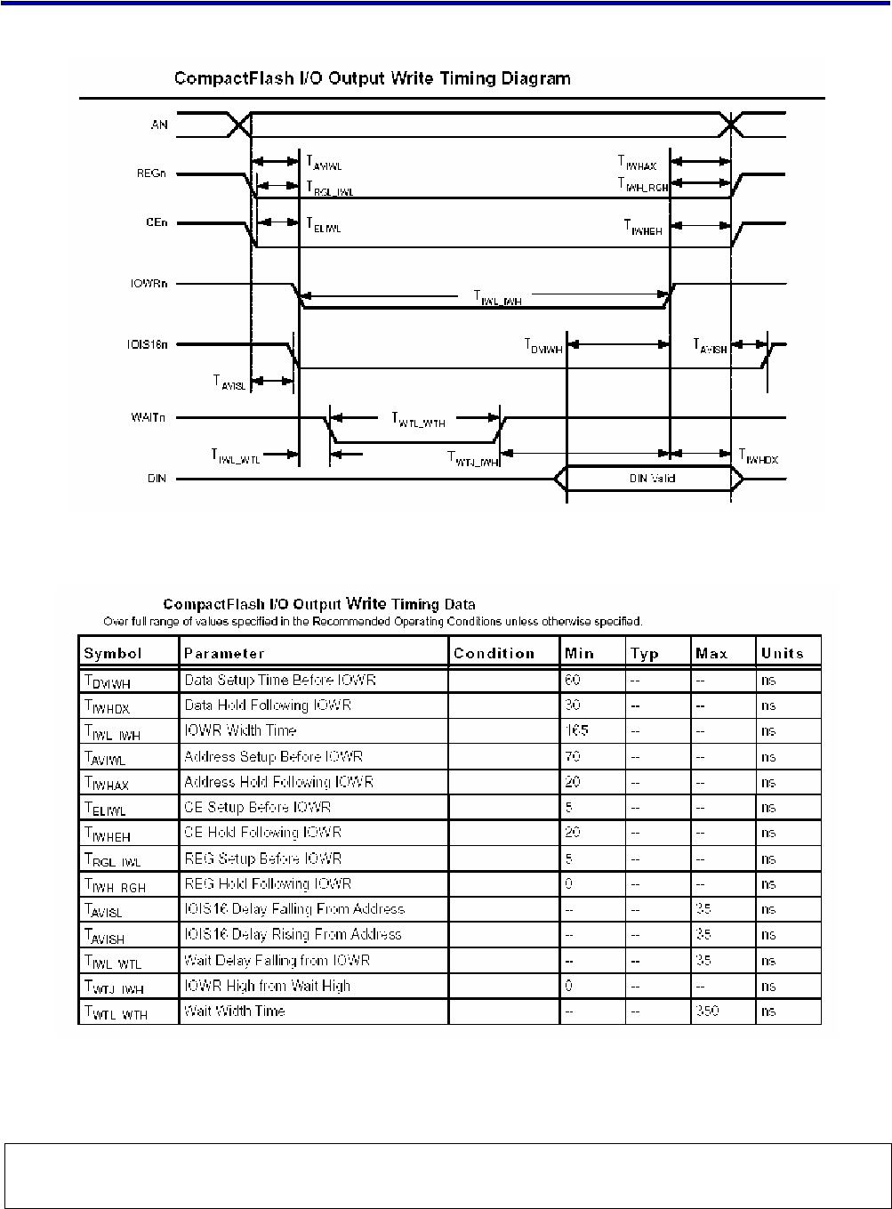
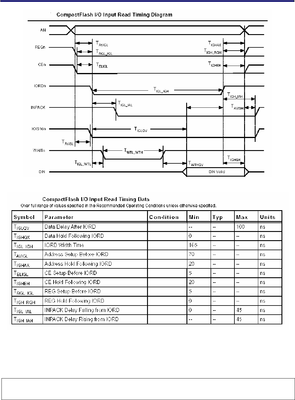
4.3.3.3. I/O READ/WRITE TIMING SPECIFICATION
802.11g Wireless LAN+BT SiP combo Module V2.2
All rights are reserved by USI. No part of this technical document can be reproduced in any form without permission of USI
. 14
4.4. WIRELESS SPECIFICATIONS
The WM-BG-MR-01 module comply with the following features and standards;
802.11g Wireless LAN+BT SiP combo Module V2.2
All rights are reserved by USI. No part of this technical document can be reproduced in any form without permission of USI
. 15
Features Description
WLAN Standards IEEE 802 Part 11b/g (802.11b/g)
Bluetooth BluetoothTM 1.1 and 1.2 compliance
Antenna Connector Two antenna connectors support 802.11b/g and BT one for each.
Coexistence Hardware signaling
Frequency Band 2.400 – 2.484 GHz
4.5. RADIO SPECIFICATIONS 802.11G
Features Description
Frequency Band 2.4000 – 2.497 GHz (2.4 GHz ISM Band)
Number of selectable Sub
channels 14 channels
Modulation OFDM, DSSS (Direct Sequence Spread Spectrum),
DBPSK, DQPSK, CCK , 16QAM, 64QAM
Supported rates 1,2, 5.5,11,6,9,12,24,36,48,54 Mbps
Maximum receive level - 10dBm (with PER < 8%)
Output Power 14 dBm +1.5/-1.0 dBm for 1, 2, 5.5, 11Mbps
14 dBm +/- 1.0 dBm for 6, 9Mbps
12 dBm +/- 1.0 dBm for > 12Mbps
Receiver Characteristics
( 3.3V, 25 degree C ) Typical Max. Unit
PER <8%, Rx Sensitivity @ 11 Mbps -87 -85 dBm
PER <8%, Rx Sensitivity @ 5.5 Mbps -89 -87 dBm
PER <8%, Rx Sensitivity @ 2 Mbps -90 -88 dBm
PER <8%, Rx Sensitivity @ 1 Mbps -92 -90 DBm
PER <10%, Rx Sensitivity @ 54 Mbps -72 -70 DBm
4.6. RADIO SPECIFICATIONS 802.15 BLUETOOTH
The Radio specification is compliant with the BluetoothTM 1.1 and 1.2 class 2 specification
Features Description
Frequency Band 2400 ~ 2483.5 MHz
Number of Channels 79 channels

802.11g Wireless LAN+BT SiP combo Module V2.2
All rights are reserved by USI. No part of this technical document can be reproduced in any form without permission of USI
. 16
Modulation FHSS (Frequency Hopping Spread Spectrum) ,
GFSK
Antenna Connector One Hirose W.FL –R –SMT(10) RF connector
4.7. BLUETOOTH RADIO CHARACTERISTICS
Features Description
Maximum Receive Level 3 dBm ( Typical )
Output Power 1 dBm ( Typical )
Sensitivity -81 dbm @ 0.1% BER @ 25 ° Celsius ( Typical )
802.11g Wireless LAN+BT SiP combo Module V2.2
All rights are reserved by USI. No part of this technical document can be reproduced in any form without permission of USI
. 17
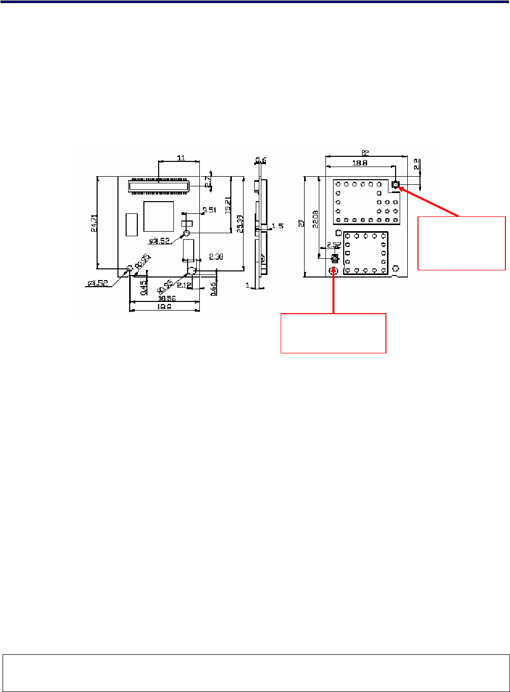
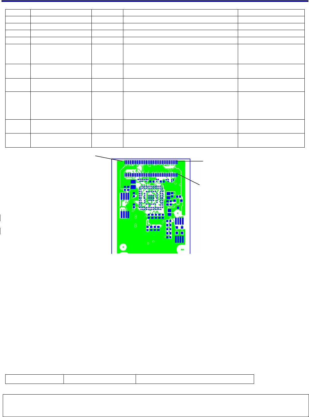
4.8. DIMENSIONS, WEIGHT AND MOUNTING
The following paragraphs provide the requirements for the size, weight and mounting of the
WM-BG-MR-01 module.
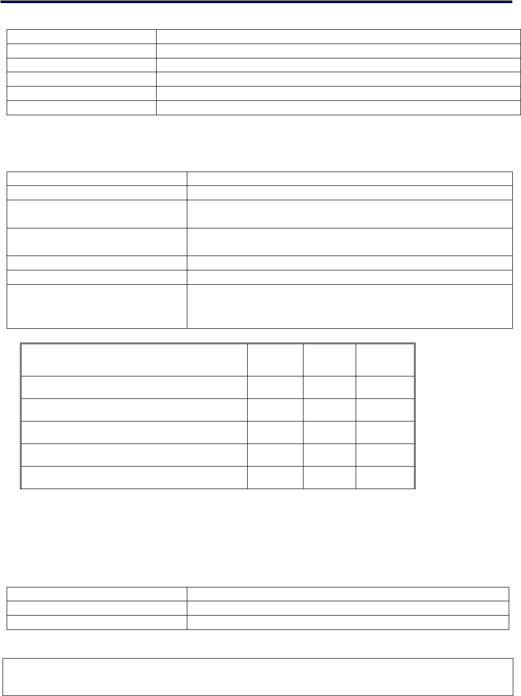
4.8.1. DIMENSIONS
The size and thickness of the WM-BG-MR-01 module is listed below:
The height – will be finalized after the module design is frozen.
4.8.2. WEIGHT
Weight shall not exceed 10 gram including the shielding.
4.8.3. MOUNTING
The WM-BG-MR-01 module is B2B mounted type component. The B2B connector and additional
screw hole provide mounting mechanism to secure the WM-BG-MR-01 module against vibration and
shock on the host system.
4.9. SHOCK AND VIBRATION
All shock and vibration test will be performed by using an interface adapter card. Additional
shock and vibration tests can be performed – on request – by using the real host being PDA,
Textbook or any other application. The interface card will provide mounting facility base on the
recommendation /application guide provided.
Antenna connector
for BT
Antenna
connector for
WiFi

802.11g Wireless LAN+BT SiP combo Module V2.2
All rights are reserved by USI. No part of this technical document can be reproduced in any form without permission of USI
. 18
Vibration
Operating Frequency sweep from 3-150-3 Hz with a constant 0.25 G
input
Non-Operational Frequency sweep from 3-150-3 Hz with a constant 0.5 G input
Shock
Operational 25 G peak within 3.75 msec in normal base position
Non-Operational 65 G peak in 3.75 msec in normal base position.
30 G within 8 msec square or trapezoidal shock in + and -
direction along the 3 axis. (Total 6 shocks)
Note: Above tests are executed without packaging material.
5. COMPATIBILITY AND INTEROPERABILITY
5.1 WIRELESS LAN
5.1.1 FEATURES
z 802.11 b/g
z WEP Encryption (64bit/128bit)
z IEEE power save mode
z Deep Sleep Mode
z Infrastructure & Ad-Hoc Mode
z Rate adaptation
z WPA TKIP security
z WPA2 (Linux ready)
z 802.1x support
z AES
5.1.2 OPERATING SYSTEMS
z WinCE 4.2/5.0, Windows Mobile 2003, Windows Mobile 5.0
z Certification tool support
z Configuration Utility support
z Linux: Slakeware 9.1, Fedora Core 1.0
Kernel: 2.4.22 & above
Certification tool support
Configuration Utility support (Wireless extension support)

802.11g Wireless LAN+BT SiP combo Module V2.2
All rights are reserved by USI. No part of this technical document can be reproduced in any form without permission of USI
. 19
5.2 BLUETOOTH KEY FEATURES OF THE HCI STACK
5.2.1 NEW BLUETOOTH V1.2 MANDATORY FUNCTIONALITY
z Adaptive Frequency Hopping (AFH)
z Faster Connections
z Flow and Flush Timeout
z LMP Improvements
z Parameter Ranges
5.2.2 OPTIONAL V1.2 FUNCTIONALITY SUPPORTED
z Extended SCO (eSCO), eV3+CRC,eV4,eV5.
z Scatter mode
z LMP Absence Masks, Quality of service and SCO handle
z L2CAP flow and error control
z Synchronisation
5.2.3 STANDARD BLUETOOTH FUNCTIONALITY
z Bluetooth components: Baseband (including LC), LM and HCI
z Standard USB v2.0 and UART (H5) HCI Transport Layers
z All standard radio packet types
z Full Bluetooth data rate, up to 723.2kbps asymmetric
z Operation with up to seven active slaves
z Maximum number of simultaneous active ACL connections:7
z Maximum number of simultaneous active SCO connections:3
z Operation with up to three SCO links, routed to one or more slaves
z Scattermet 2.5 operation
z All standard SCO voice coding, plus “transparent SCO”
z Standard operating modes: page, inquiry, page-scan and inquiry-scan
z All standard pairing, authentication, link key and encryption operations
z Standard Bluetooth power saving mechanisms: Hold, Sniff and Park
modes, including “Forced Hold”
z Dynamic control of peers’ transmit power via LMP
z Master/Slave switch
z Broadcast
z Channel quality driven data rate
z All standard Bluetooth Test Modes
6. CONFIGURABILITY
No user configuration needed. The CIS and MAC Address will be loaded during production of
the WM-BG-MR-01 module.

802.11g Wireless LAN+BT SiP combo Module V2.2
All rights are reserved by USI. No part of this technical document can be reproduced in any form without permission of USI
. 20
7. OPERATING SYSTEM COMPATIBILITY
Drivers are supported for the following OS:
Windows CE 3.0 /4.2/5.0, PPC2003, 2004, 2005
Linux.
8. LEGAL, REGULATORY & OTHER TECHNICAL CONSTRAINTS
The WM-BG-MR-01 module is pre-tested to ensure that all requirements met as set forth in the
following sections.
Final certification (module certification) requires the antenna of targeted system with a lead-
time of 6 weeks. The product deliverable shall be a pre-tested WM-BG-MR-01 module. No
module level certification on WM-BG-MR-01 module.
8.1. EMC
The module will be pre-tested to ensure that we can certify the product in the following
countries when final certification will be performed on products and or platforms.
US. FCC CFR47 Part 15-B, Class B
Canada. CSA C22.2, Class B
Europe. 89/336/EEC, EMC Directive, including CE Mark
ETS300 826, EMC standard for 2.4GHz wideband transmission systems
EN55022, Class B (Emissions)
EN50082-1 (Immunity)
EN61000-3-2 (Harmonic AC current emissions)
Japan. VCCI Standard, Class 2 (Emissions)
Korea (MIC)
8.2. PRODUCT SAFETY SPECIFICATION
The WM-BG-MR-01 module is tested and pass successfully the following criteria;
The testing is to assure the quality of safety requirement on module. Final certification will
be conducted on system level.
UL1950 /CSA C22.2.950
EN60 950 (IEC 950)
CB scheme certification from National certification body as listed in CB bulletin No. 96A.
8.3. COMPONENT SPECIFICATION
All components used in this device meet the following component approval requirements.

802.11g Wireless LAN+BT SiP combo Module V2.2
All rights are reserved by USI. No part of this technical document can be reproduced in any form without permission of USI
. 21
PRINTED WIRING BOARDS: The printed wiring boards shall be Underwriters
Laboratories Inc. "Recognized Component" (ZPMV2) under the category for Printed
Wiring Boards, and shall be flammability rated 94V-1 or less flammable. The board
material shall be rated 130°C minimum.
CONNECTORS: Any connectors, if used, shall be Underwriters Laboratories, Inc.
"Recognized" (ECBT2/RTRT2) in accordance with the requirements in the UL Standard
for Safety, UL 498. Any polymeric connector housing shall be molded of plastics rated
UL 94V-2 or less flammable when tested to UL 94.
WIRING: Any wiring material, if used, shall be UL Recognized Component Appliance
Wiring Material (AVLV2). Wire shall be minimum rated 30V, 105°C.
PLASTIC PARTS - Any plastic parts used shall be molded of plastics that are UL
"Recognized" (QFMZ2) and rated UL 94V-2 or less flammable when tested to UL 94.
“PB FREE” - The entire component Suppliers has to support Green requirement base on
USI’s policy. All of the components which including process and materials has to be Lead
Free.
8.4. RADIO REQUIREMENTS AND APPROVALS
The WM-BG-MR-01 module is tested with adapter card to comply with following standard.
The testing is to assure the performance of regulatory requirement on module. Final
certification will be conducted on system level.
US/CAN: FCC CFR47 Part 15.247
Japan: TELEC
Korea: MIC
Europe: ETS 300-328 V1.6.1

802.11g Wireless LAN+BT SiP combo Module V2.2
All rights are reserved by USI. No part of this technical document can be reproduced in any form without permission of USI
. 22
8.5. PRODUCT MARKING
The Module is marked by laser marking which containing the following information:
Description: WM-BG-XX-XX
Serial number: yyllwkxxxx
Revision: format to follow USI revision level in PDM System
For the serial number the following format will be followed:
yy = last two digits of current year
ll = Assembly Location:
UT = USI Taiwan
UM = USI Mexico
UC = USI China
wk = current week (week period = starting on Monday)
xxxx = consecutive number, starting at 0000 at beginning of each week.
8.6. ENVIRONMENTALLY SAFE MATERIAL RESTRICTIONS
The use of polychlorinated biphenyls (PCB’s) is prohibited (specifically) as dielectric in
capacitors or transformers.
Electrolytic capacitors shall not be composed of any quaternary salt ammonium and/or
gamma-butyrolactone (i.e. no el caps allowed).
No CFC's (chlorofluorocarbons) shall be used anywhere in the manufacture of this product.
The use of tantalum capacitors should be minimized in any product of the product family
[including the power-supply]. Where the use of tantalum caps cannot be avoided, provisions
must be made in the manufacturing process to prevent reverse polarization.
The WM-BG-MR-01 module hardware design should take the safety of operation into
consideration and prevent the potential risk on Labor safety for manufacturing process.
802.11g Wireless LAN+BT SiP combo Module V2.2
All rights are reserved by USI. No part of this technical document can be reproduced in any form without permission of USI
. 23
9. FUNCTIONAL DESCRIPTION
The WM-BG-MR-01 module provides and interfaces between Compaq Flash or PC Card
Interface, SDIO , SPI which suitable for wide range high-end processors or low cost ARM7 or
other similar type of processors.
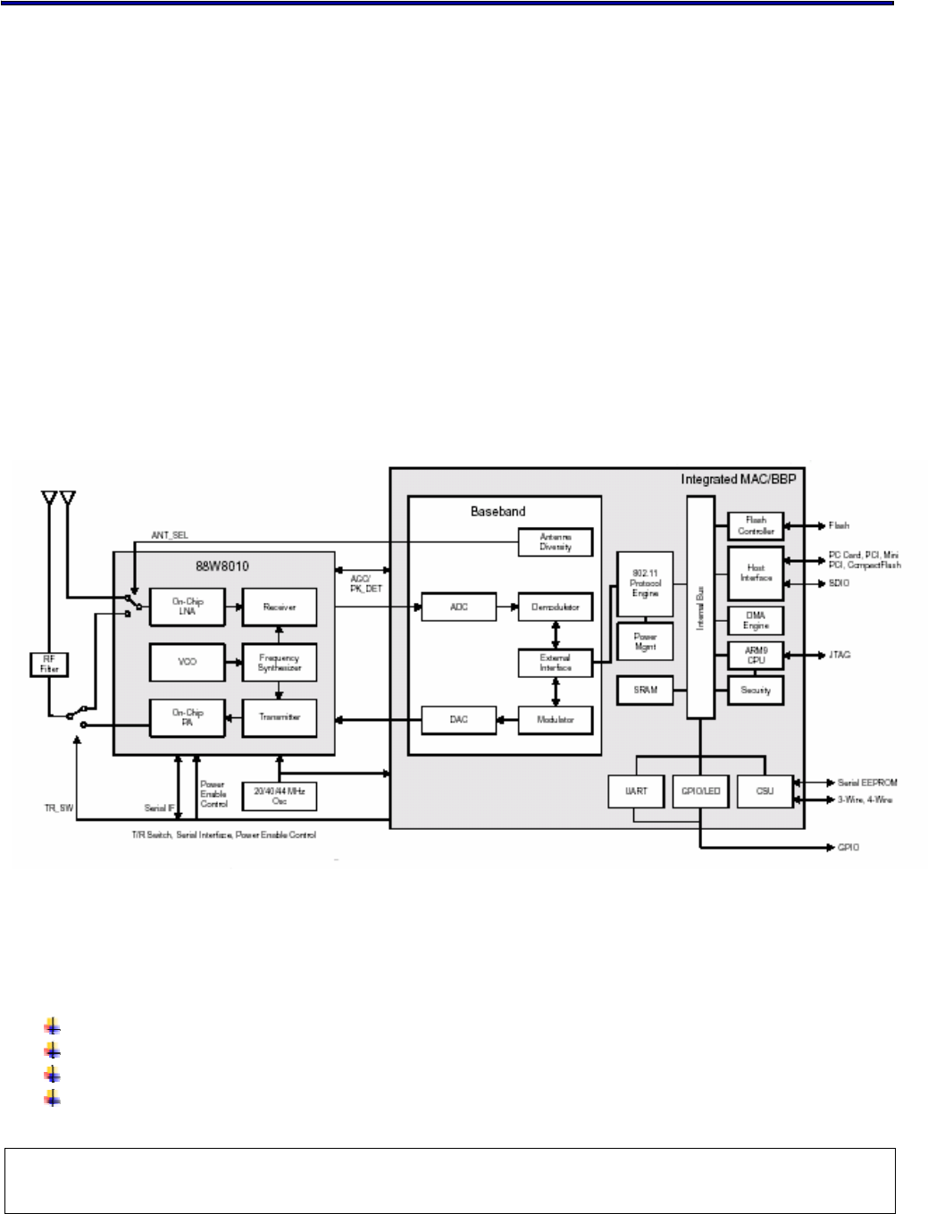
The core of the WM-BG-MR-01 module is the Marvell 88W83 Chipset solution.
The module is design base on the Marvell Libertas solution which contain the flip chip package
MAC/BB chip - 88W8385 , The transceiver 88W8015 low profile package IC to reduce the size
of module. All the other components can be implement by all means to reach the mechanical
specification.
A simplified block diagram of the WM-BG-MR-01 module is depicted in the Fig. below.
To be updated with BT
9.1. HARDWARE
The following sections provide the requirements for the different physical interfaces of the
wireless module :
Host Interface
Antenna connections
LED control signal
Bluetooth WiFi coexistence control signals
88W8385
802.11g Wireless LAN+BT SiP combo Module V2.2
All rights are reserved by USI. No part of this technical document can be reproduced in any form without permission of USI
. 24
Power
GND
9.2. HOST INTERFACE
The host interface will be compatible with CompactFlash (PCMCIA) standard, 16 bit I/O bus.
Signals which are not used won’t be routed to the physical interface (connector). The host
interface of Combo SiP Bluetooth portion is compliant with UART interface, the default baud
rate setting is 115.2kbps and the optional range is from 9.6kbps to 921.6kbps.
On Board connector
Molex 53794-0608 or 55560-0607 [Socket, 60 pins, with positioning protection, stack
height which is able to support 1.5 mm]
Datasheet_Molex_53
794-0608.pdf
Datasheet_Molex_55
560-0607.pdf
Host System:
Host System Connector
Molex 54722-0607 [Header, 60 pins, with positioning protection, stack height 1.5mm]
Datasheet_Molex_54
722-0607.pdf
Pin definition
[ …] means optional function of the pin.
PD : Signal pull down internally in the chip by 50K ohm while initialization.
PU : Signal pull up internally in the chip by 100K ohm while initialization.
5VT: 5 Volt tolerance pin
xxx_B : Signal pins end with _B are “active high”
Pin #
Definition Draft Description Type
WM-BG-
MR-01 CF+ interface
1 GND GND GND
2 D03 HD3 CompactFlash Data bit[3] IO, PU, 4mA
3 D04 HD4 CompactFlash Data bit[4] IO, PU, 4mA
4 D05 HD5 CompactFlash Data bit[5] IO, PU, 4mA

802.11g Wireless LAN+BT SiP combo Module V2.2
All rights are reserved by USI. No part of this technical document can be reproduced in any form without permission of USI
. 25
5 D06 HD6 CompactFlash Data bit[6] IO, PU, 4mA
6 D07 HD7 CompactFlash Data bit[7] IO, PU, 4mA
7 -CE_1 HCE1_B Card Enable1 is driven by the host
system and is used as select strobe in
both I/O and memory mode. Enables
even numbered address bytes.
Input, PU
8 A10 HA10 CompactFlash Address bit [10]. See
address bit [0] description. Input, PU
9 -OE
SD_CMD HOE_B OUTPUT ENABLE is driven by the host
during a memory Read Access.
SD_CMD : SDIO Command Line
Input, PU
10 A09
SD_DAT2 HA9 CompactFlash Address bit [9]. See
address bit [0] description.
SD_DATA2 : SDIO DATA LINE 2
Input, PU
11 A08 HA8 CompactFlash Address bit [8]. See
address bit [0] description. Input, PU
12 A07 HA7 CompactFlash Address bit [7]. See
address bit [0] description. Input, PU
13 VCC VCC_WLA
N 3.3V supply voltage for WLAN Input 3.3 V
14 A06 HA6 CompactFlash Address bit [6]. See
address bit [0] description. Input, PU
15 A05 HA5 CompactFlash Address bit [5]. See
address bit [0] description. Input, PU
16 A04 HA4 CompactFlash Address bit [4]. See
address bit [0] description. Input, PU
17 A03 HA3 CompactFlash Address bit [3]. See
address bit [0] description. Input, PU
18 A02 HA2 CompactFlash Address bit [2]. See
address bit [0] description. Input, PU
19 A01 HA1 CompactFlash Address bit [1]. See
address bit [0] description. Input, PU
20 A00 HA0 CompactFlash Address bit [0]. The
address lines A[10:00] along with
the REG si
g
nal are used to select the
following:
• The I/O port address register
• The memory mapped port address
register
• A byte in the card's information
structure (CIS)
Input, PU
21 D00 HD0 CompactFlash Data bit[0] IO, PU, 4mA
22 D01 HD1 CompactFlash Data bit[1] IO, PU, 4mA
23 D02 HD2 CompactFlash Data bit[2] IO, PU, 4mA
24 -IOIS16 HIOIS16_
B I/O port is 16bits Out, 6mA
25 -CD2 CD2 Normal operation, this pin is functionally
for card detection. Out, 6mA
26 N/A TXD_B UART Data output, Active High Output, WPU, 1µA
27 N/A RTS_B UART Request to send, Active low,
Tristatable, Pulled-up Output, WPU, 1µA
28 N/A PCM_In Synchronous Data input
29 N/A VCC_WLA
N 3.3V power supply for WLAN Input

802.11g Wireless LAN+BT SiP combo Module V2.2
All rights are reserved by USI. No part of this technical document can be reproduced in any form without permission of USI
. 26
30 GND GND
31 GND GND
32 D10 HD10 CompactFlash Data bit[10] IO, PU, 4mA
33 D09 HD9 CompactFlash Data bit[9] IO, PU, 4mA
34 D08 HD8 CompactFlash Data bit[8] IO, PU, 4mA
35 -STSCHG HSTSCHG
_B Card status changed Output, 4mA
36 -SPKR PCM_Sync Synchronous Data strobe Input PD, 4mA
37 -REG HREG_B Register select and I/O enable Input, PU
38 -INPACK HINPACK_
B INPUT ACKNOWLEDGE is driven by WM-
BG-MR-01. Is asserted when the device
is selected and the device is responding
to an I/O Read command.
Output, 2mA
39 -WAIT HWAIT_B HWAIT_B is driven by WM-BG-MR-01 and
allows for extending the memory or I/O
cycle
Output, 4mA
40 RESET
HRESET Used to asynchronously reset WLAN.
High active.
Input, PU
41 N/A N/A Reserved. Keep connection open on Host
side N/A
42 N/A WLAN_LED
_B WLAN LED control si
g
nal, driven the LED
indicating the link status of WLAN. Active
low. Output, 4mA
43 N/A PCM_OUT Synchronous Data output
44 IREQ
IREQ_B Ready/Busy or Interrupt request.
In memory mode, this si
g
nal indicates
the ready or busy status of the card.
When held hi
g
h, the card is ready to
accept a new data transfer. When held
low the card is busy.
In I/O mode, this signal is used to
indicate an interrupt condition.
Output, 4mA
45 -WE HWE_B WRITE ENABLE is driven by the host
during a memory Write Access Input, PU
46 -IOWR
SD_DAT3 HIOWR_B I/O Write Strobe is driven by the host
and is asserted when the host wants to
write to an on-chip I/O register
SD_DAT3 : SDIO DATA LINE 3
Input, PU
47 -IORD
SD_DAT1 HIORD_B I/O Read Strobe is driven by the host
and is asserted when the host wants to
read from an on-chip I/O register
SD_DAT1 : SDIO DATA LINE 1
Input, PU
48 -VS1 -VS1
T
his pin is connected to Ground on
module to indicate the volta
g
e of this
module is 3.3V card. GND
49 -CE2
SD_CLK HCE2_B CARD ENABLE2 is driven by the host
system and is used as select strobe in
both I/O and memory mode. Enables odd
numbered address bytes
SD_CLK : SDIO CLOCK
Input, PU
802.11g Wireless LAN+BT SiP combo Module V2.2
All rights are reserved by USI. No part of this technical document can be reproduced in any form without permission of USI
. 27
50 D15 HD15 CompactFlash Data bit[15] IO, PU, 4mA
51 D14 HD14 CompactFlash Data bit[14] IO, PU, 4mA
52 D13 HD13 CompactFlash Data bit[13] IO, PU, 4mA
53 D12 HD12 CompactFlash Data bit[12] IO, PU, 4mA
54 D11 HD11 CompactFlash Data bit[11] IO, PU, 4mA
55 N/A BT_LED_B BT LED control signal which drives the
LED to indicate the activity of Bluetooth.
Active low.
Output, 4mA
56 N/A RXD_B UART Data input, active High, Pulled
down (weak) Input, WPD, 1µA
57 N/A CTS_B UART Clear to Send, Active low, Pulled
down (weak) Input, WPD, 1µA
58 N/A
SD_DAT0 PCM_CLK Synchronous Data clock
SD_DAT0 : SDIO DATA LINE 0
59 N/A VCC_BT 3.3V supply voltage for Bluetooth Input
60 GND GND
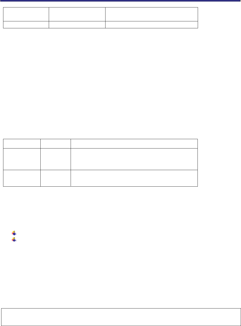
Fig 1: Pin 1 assignment and indication Drawing
( To be updated with latest design)
9.2.1. LED INTERFACE
The Wireless Module will provide two control signals to the host and capable to drive an LED
to indicate the connectivity and operating status.
The WM-BG-MR-01 have 2 LED’s (output) via 60 pins connector for feedback to the user on
the current WLAN activity state. The signaling will reflect status / activity as described in the
table below. Those two signals are provided via the board to board connector with the
following pin assignment.
Pin No Pin description Function description
Pin 59
Pin 60
Pin 59
Pin 1
Pin 60
802.11g Wireless LAN+BT SiP combo Module V2.2
All rights are reserved by USI. No part of this technical document can be reproduced in any form without permission of USI
. 28
42 WLAN_LED Check firmware specification
of GPIO(1) with Marvell
55 BT_LED_B Link activity of Bluetooth
9.2.2. ANTENNA INTERFACE
No antenna diversity supported on the Wireless Module.
The output impedance of the cable is 50 Ohms.
Antenna Connector: Hirose W-FL-R-SMT(10)
9.2.3. BLUETOOTH INTERFACE
There are interfaces signal to routed between WiFi and Bluetooth to provide coexistence with
802.15 Bluetooth modules.
The BT co-existence interface supported, which is 2 Wire CSR co-existence.
The control signals are provided via the 60 pins B2B connector with the interface defined as
below:
Symbol Interface “Signal name” & description
BTACT
2 Wire-CSR
“BT _Priority”
This pin indicates to WLAN BCA device that BT module is
active or will soon be active to TX/RX stage.
WLAN_active
2 Wire-CSR
“Wlan_Active”, This pin indicates to BT module that WLAN
is active or will soon be active to TX/RX stage.
Note 1: “WLAN BCA” device is a functional block in 88W8385 works as Bluetooth co-existence management .
9.3. SOFTWARE
The following source code will be provided for porting to the embedded system under the SLA
with chipset supplier
Linux source code
Source code of development utility base on Windows CE
10. DESIGN FOR EXCELLENCE (DFX)
10.1. TESTABILITY
The WM-BG-MR-01 module can be tested on the by using adapter card or similar interface.
The adapter card must be such that from the FTS the WM-BG-MR-01 module is seen and
recognized as PC Card or Compaq Flash.

802.11g Wireless LAN+BT SiP combo Module V2.2
All rights are reserved by USI. No part of this technical document can be reproduced in any form without permission of USI
. 29
y No additional test pins are required to support in-circuit testing.
10.2. LOGISTICS
All customer specific requirements – customization – will be implemented at the highest
possible level to support build to order and keep the number of modules in SMT to a minimum.
Additional module variants might be added base on business potential.
11. HUMAN FACTORS
Due to the nature of this product (embedded module) no human factors required
12. INDUSTRIAL DESIGN
Due to the nature of this product (embedded module) no industrial design requirements are
required.
13. RELIABILITY
The WM-BG-MR-01 module guarantee an MTBF of 150,000 hrs based on an ambient
temperature and workload of 2,920 hours. The workload is based on a unit working for 8 hours
per day, 365 days per year.
The MTBF estimation base on is Bell code standard, Class II.
14. PACKAGE
To be updated.

802.11g Wireless LAN+BT SiP combo Module V2.2
All rights are reserved by USI. No part of this technical document can be reproduced in any form without permission of USI
. 30
Marvell is Trademark of 3’rd Party.
For Additional information, please contact the following:
Universal Scientific Industrial Co., Ltd.
Headquarters
141, Lane 351, Taiping Road, Sec. 1, Tsao-Tuen, Taiwan,
Http://www.usi.com.tw
Tel: + 886-49-2350876, 2325876
Fax: +886-49-3439561, 2337360,2351093
E-mail:usi@ms.usi.com.tw