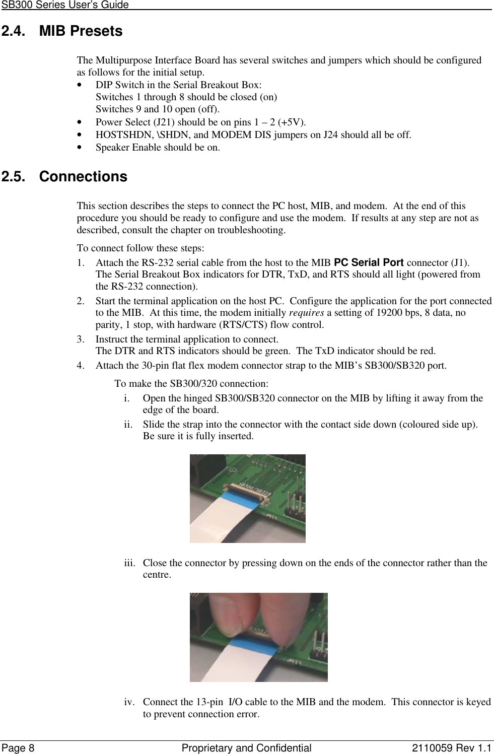
General Dynamics Itronix T5200SB300 T5200, CDPD Wireless handheld terminal User Manual 2110059
General Dynamics Itronix Corporation T5200, CDPD Wireless handheld terminal 2110059
Contents
- 1. SB300 Series User Guide
- 2. T5200 User Manual
SB300 Series User Guide


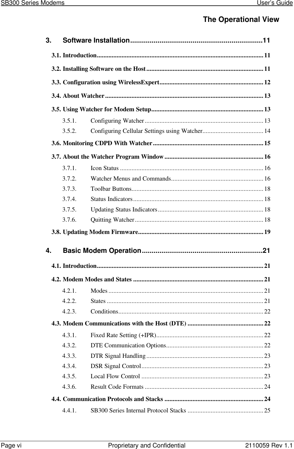


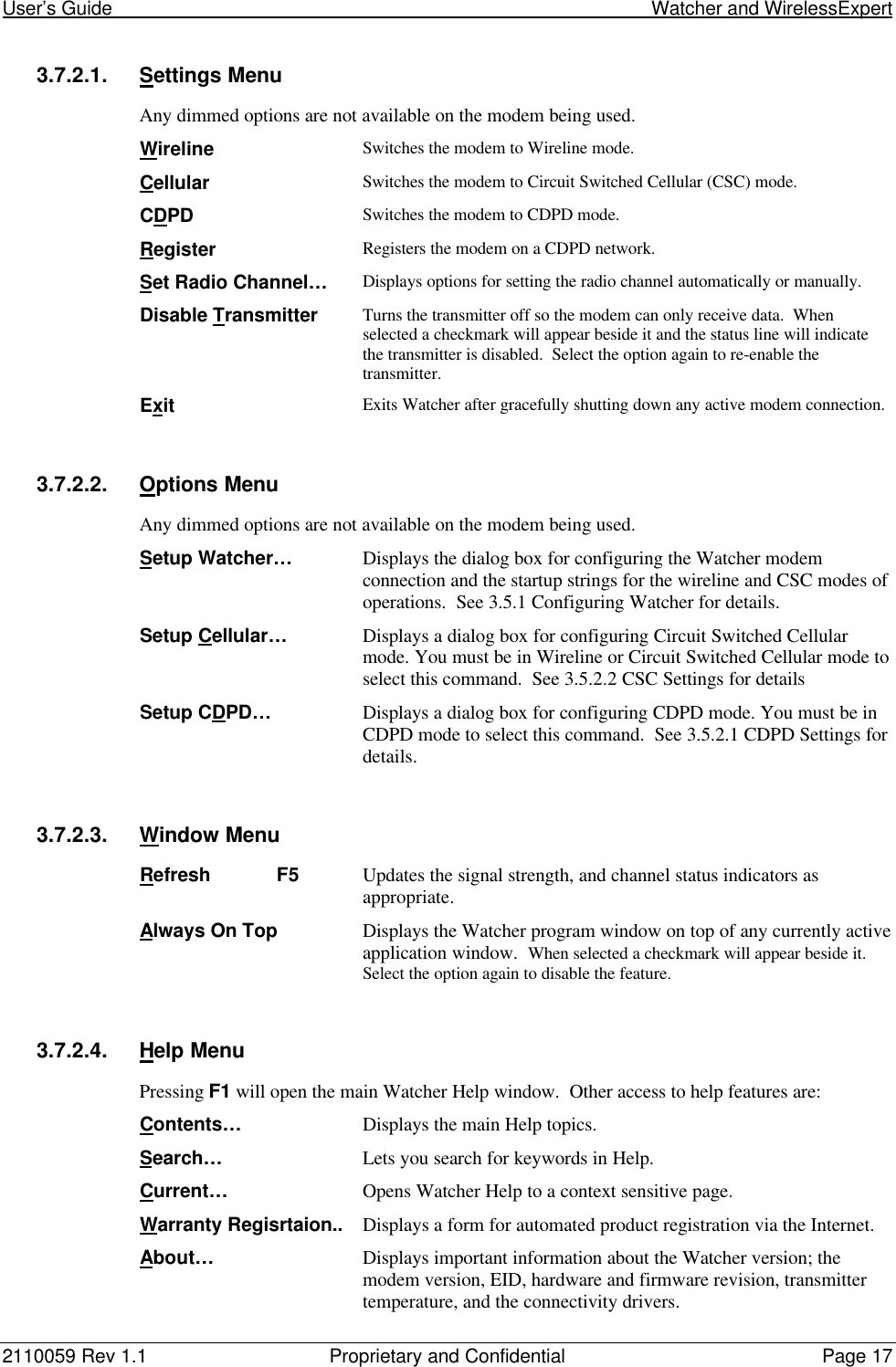


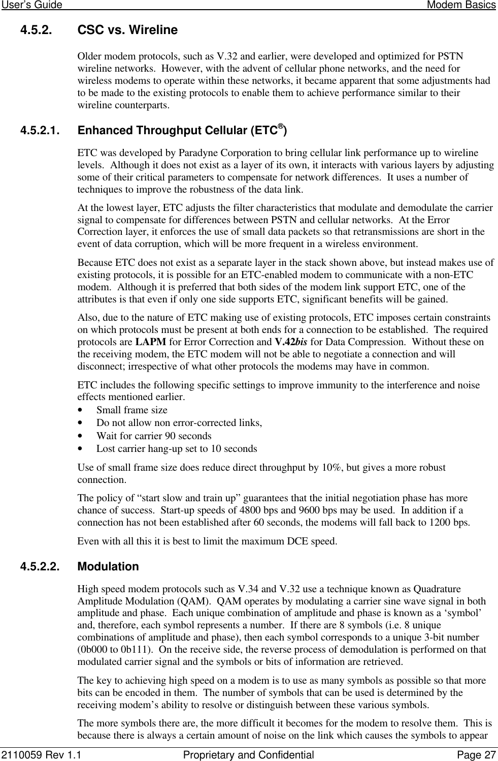
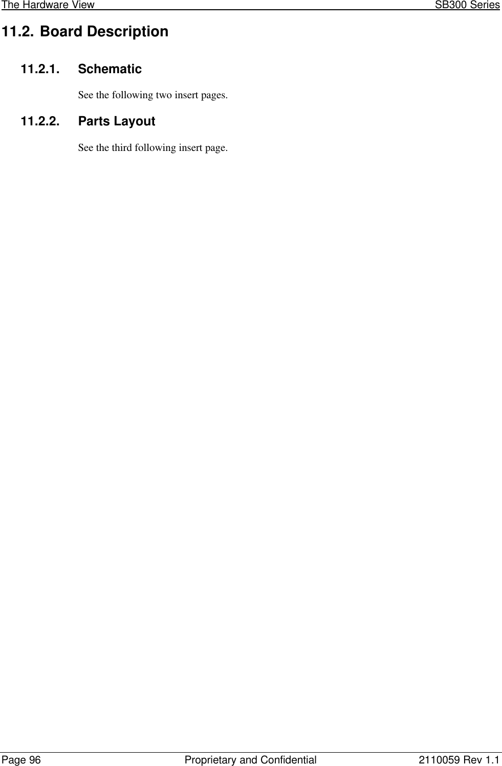
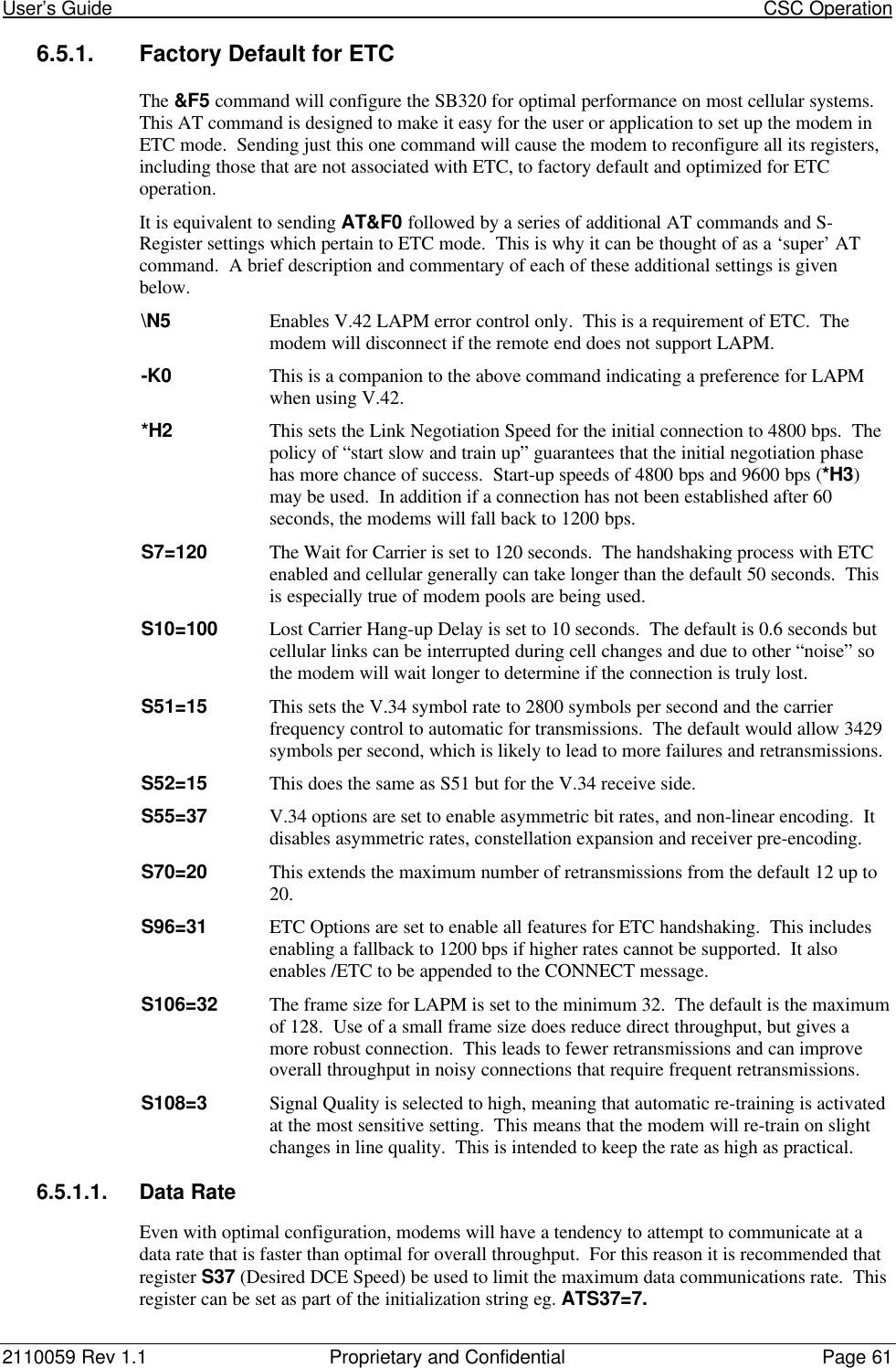
![User’s Guide CDPD Operation2110059 Rev 1.1 Proprietary and Confidential Page 334. +WPNEILIST to display the list and verify the new entry.5. +WS174=n where n indicates the channel side preference. Values are:0 – A side preferred,1 – B side preferred,2 – A side only,3 – B side only.NOTEThe channel side preference is stored in a register not associated with a particularentry in the NEI table. The preference will be used for all NEI registrations.5.2.2. SPNI MatchingIf you want to restrict the modem to only using channels belonging to a particular list of serviceproviders you can enter a table of SPNI values. When the modem is finding a channel, it willcheck the SPNI of each channel against entries in this table. If there is no match, the modem willreject the channel and continue searching.If the table is empty, the SPNI matching feature is disabled.NOTEIf you set SPNI matching and also use +WPCHAN to assign a channel manually, theassigned channel will not lock if the SPNI fails to match. The modem will not be ableto register because it will not look for another channel if you have manually set achannel. The status of channel lock can be checked using +WPRSSI.5.2.2.1. SPNI Table ConfigurationTo manage the use of SPNI matching using AT Commands enter the following commands (theAT is omitted for brevity):Read the Current SPNI Table1. +WPSPNI? Displays the SPNI Table. If the table is empty then SPNI matching is disabled.If there is at least one entry then SPNI matching is enabled.Disable SPNI Matching1. +WPSPNI= By not entering parameters, the table will be erased. An empty table disablesSPNI matching.Enable SPNI Matching1. +WPSPNI=n[,n[,…n]] where n is a SPNI value and multiple values are separated bycommas. The list of parameters provided will replace any previous table. You cannot appendentries to an existing table. You may enter up to 10 values in the table. By entering one ormore SPNI values, the SPNI matching feature is automatically enabled.5.3. CDPD Network RegistrationNote that network registration must be performed before communication across the network canbegin. Registering on the network is distinct from opening a session. Registration simplyconfirms a connection to the network as a whole and authenticates your modem’s credentials.Data Carrier Detect (DCD) is tied to sessions not network registration. A session does not beginuntil you originate a session (client) or answer one (server).The modem can be set to register manually (on command) or automatically when it enters CDPDmode. The NEI address used for registration is determined differently for each method.](https://usermanual.wiki/General-Dynamics-Itronix/T5200SB300.SB300-Series-User-Guide/User-Guide-49397-Page-44.png)


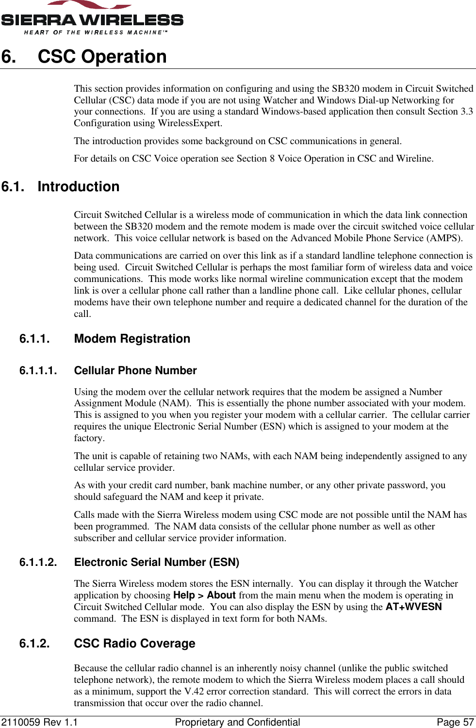
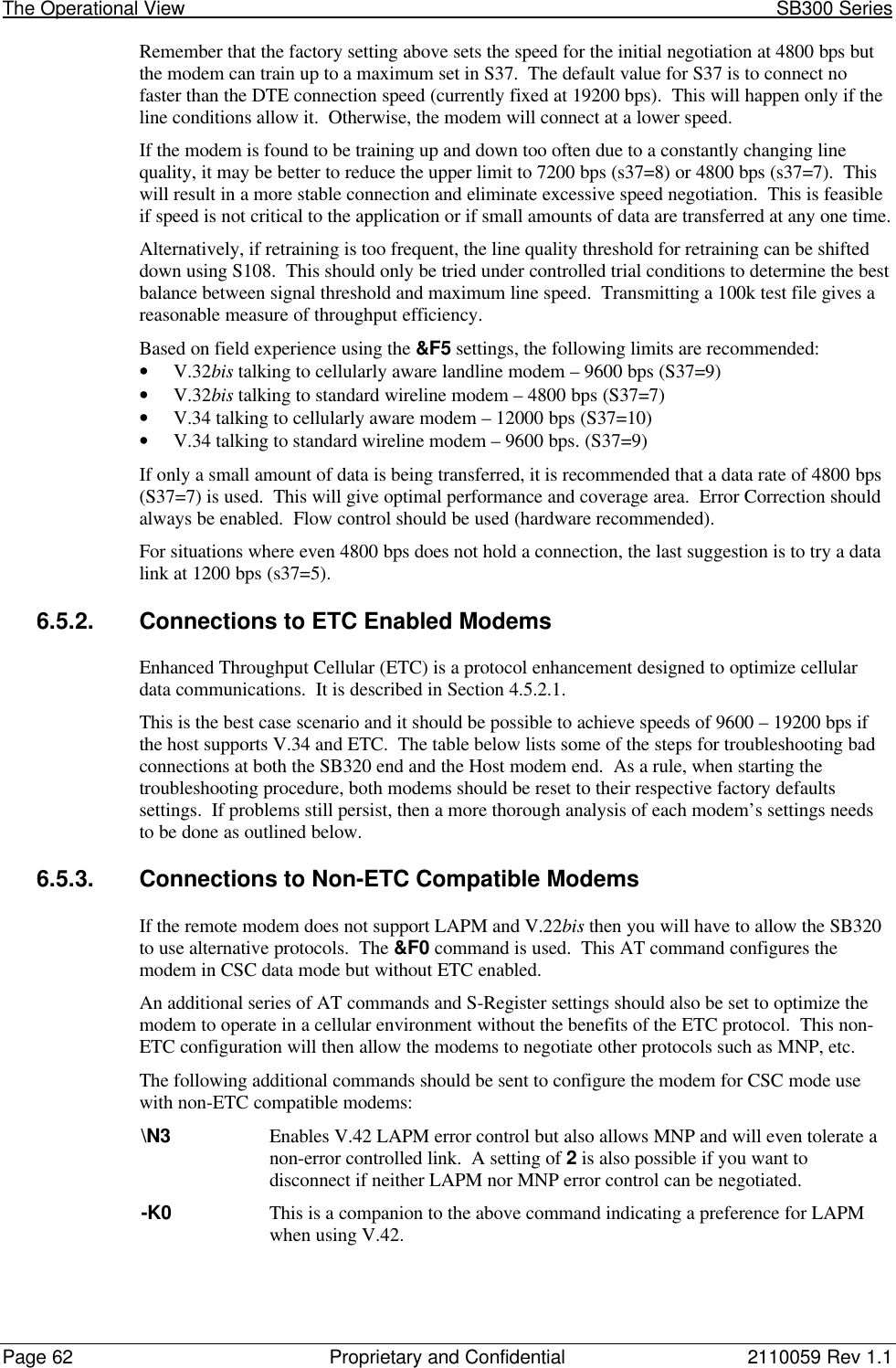


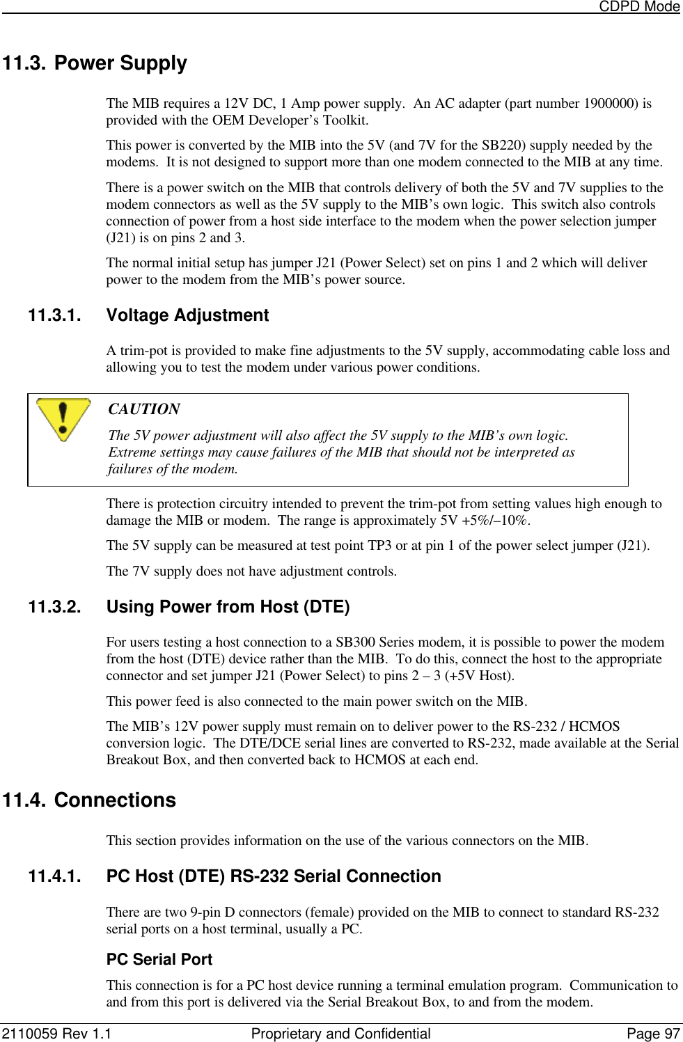
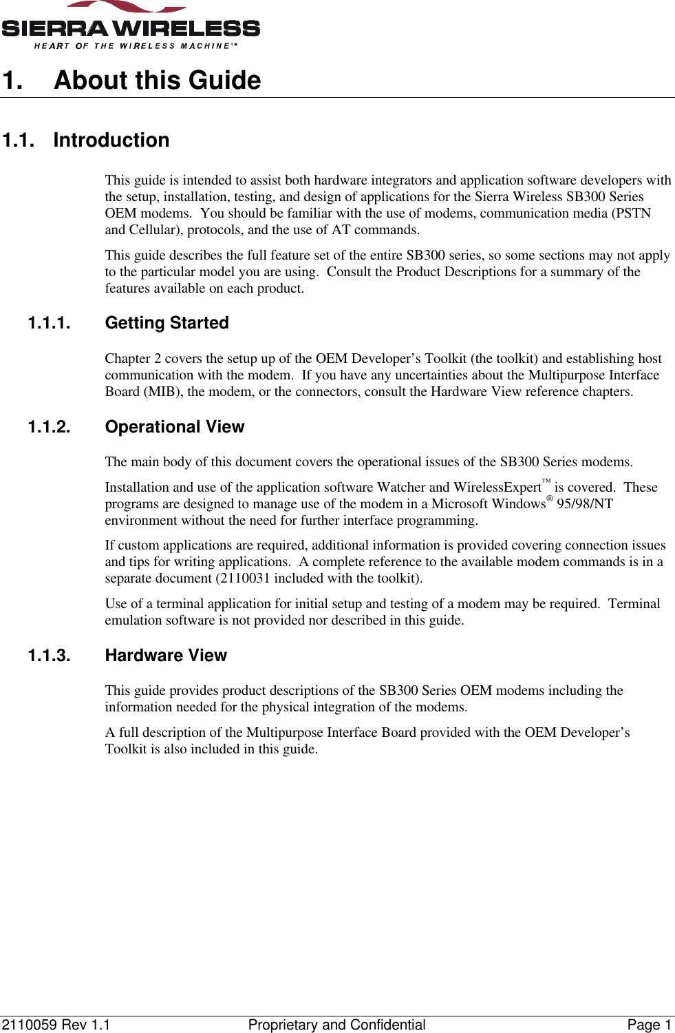
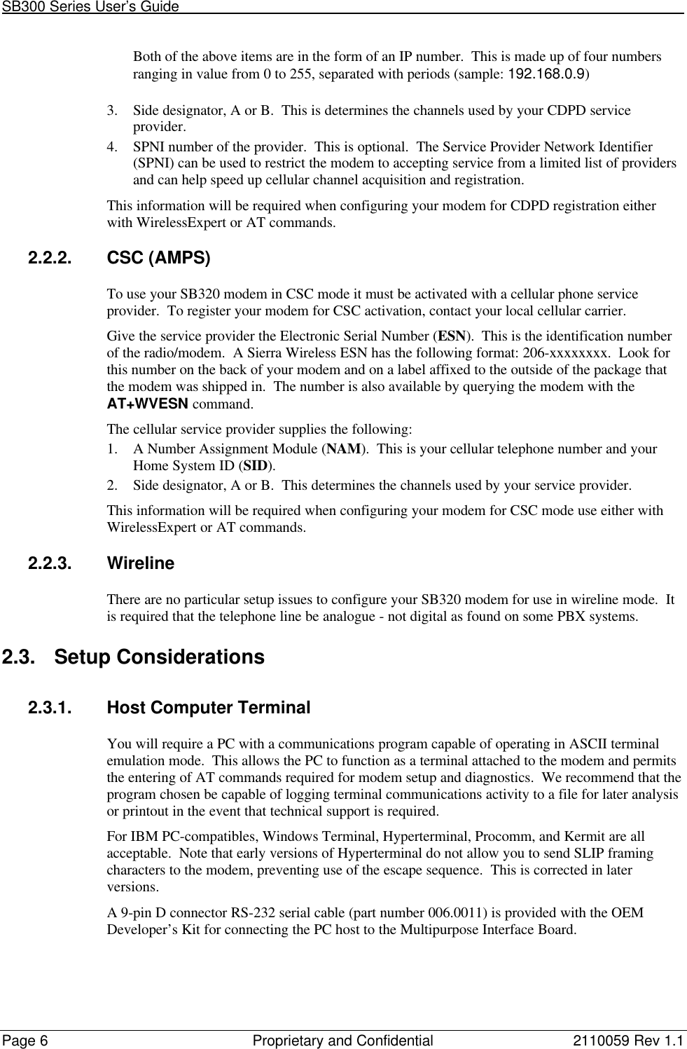
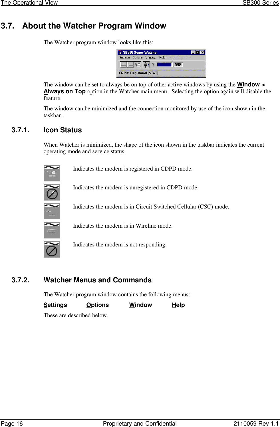
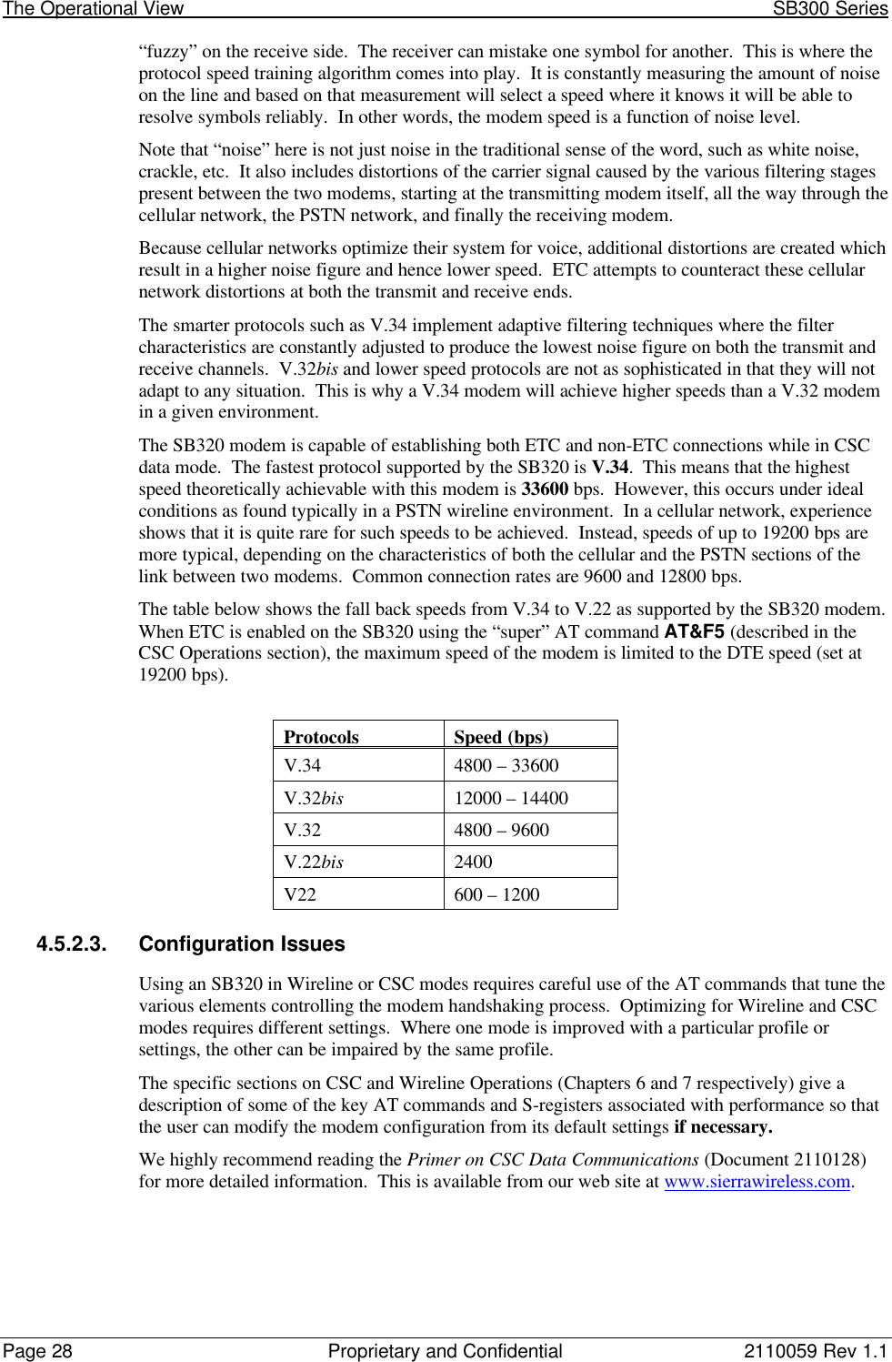
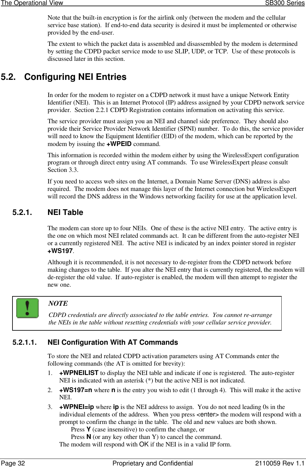
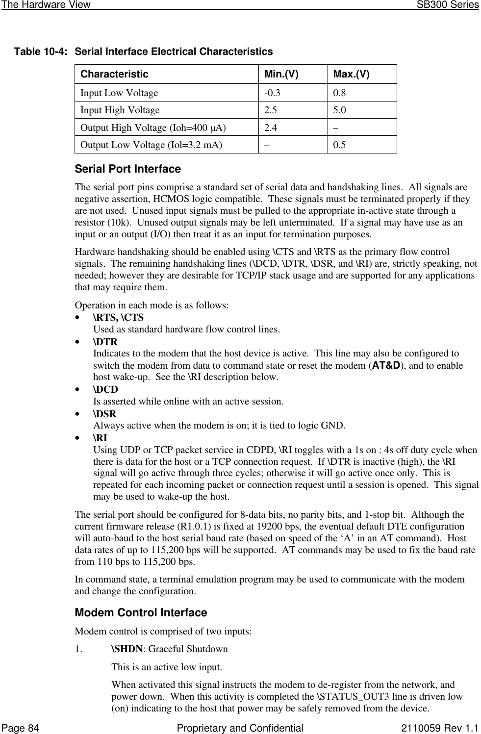
![2110059 Rev 1.1 Proprietary and Confidential Page 8110.3. SB300 CDPD ModemPart number 110003410.3.1. Mechanical10.3.1.1. Physical DescriptionThe SB300 comes in a Type III package, andincludes a 30-pin, 0.5mm pitch ZIF connector forthe host interface, a MMCX connector for theantenna, and a status LED. Dimensions (in mm) are as follows:Figure 10-1: SB300 Physical Dimensions [mm].10.3.1.2. MountingThe SB300 uses an industry standard Type III frame-kit, and as such will fit into PC Card rails.Alternatively, two clips or a bracket may be used to secure the module. There are also twomounting holes provided on either side of the ZIF serial connector.Figure 10-2: SB300 Package Views.](https://usermanual.wiki/General-Dynamics-Itronix/T5200SB300.SB300-Series-User-Guide/User-Guide-49397-Page-92.png)


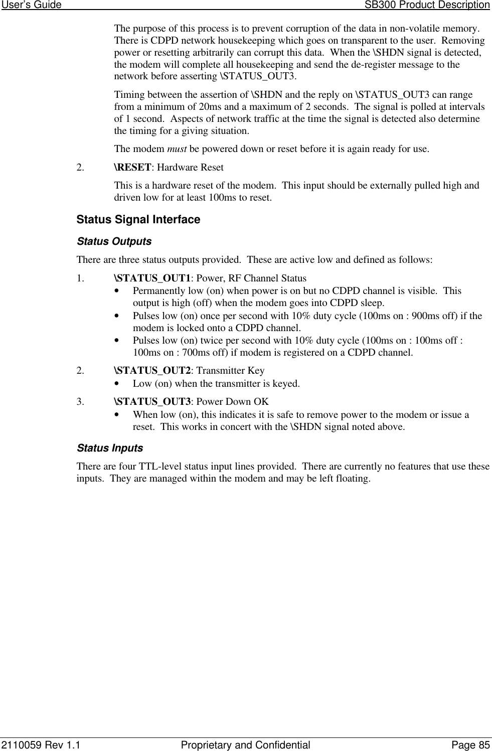

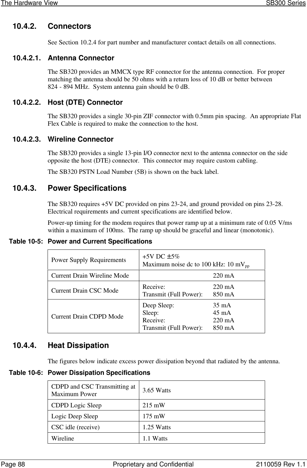
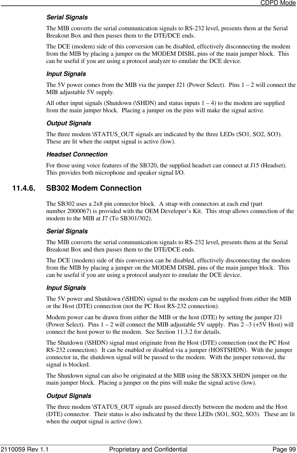
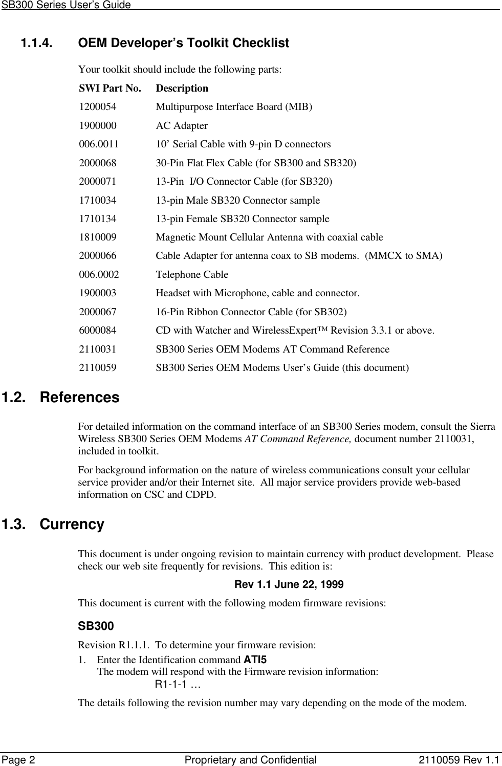
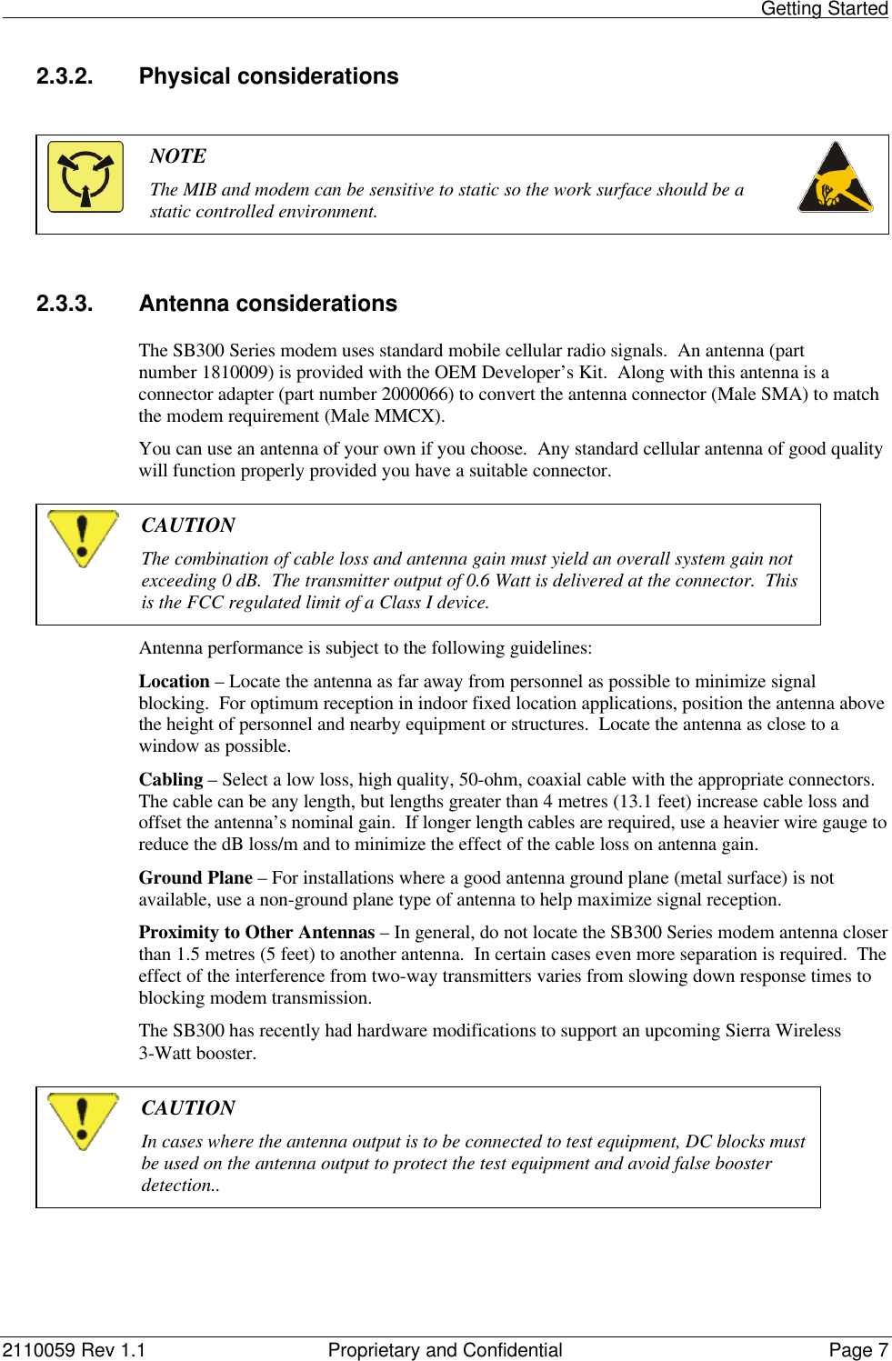
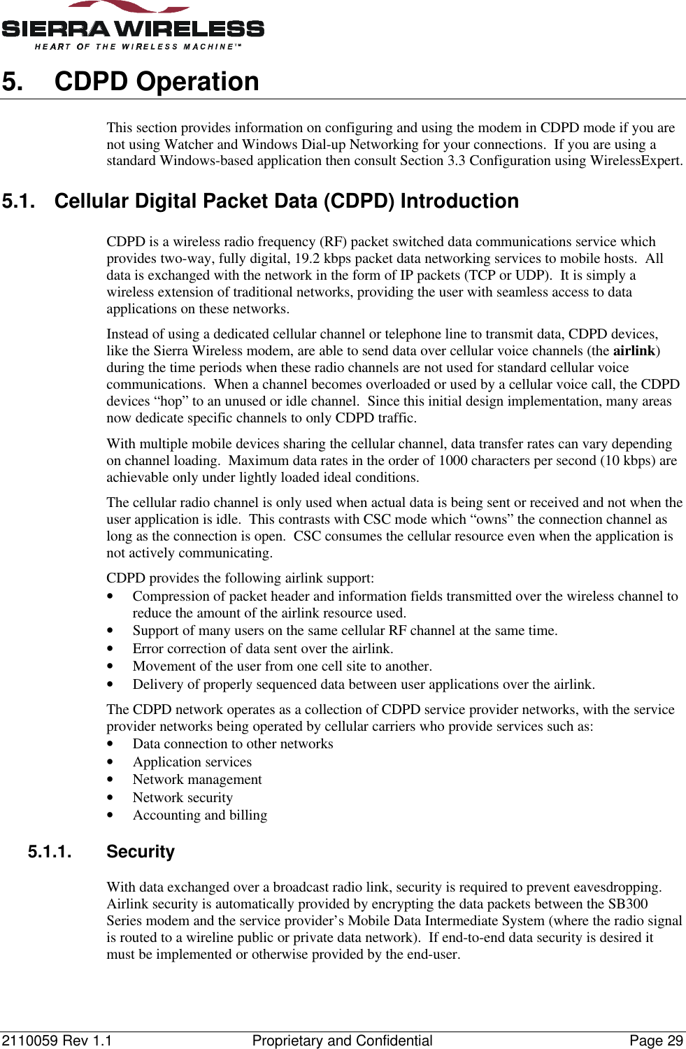
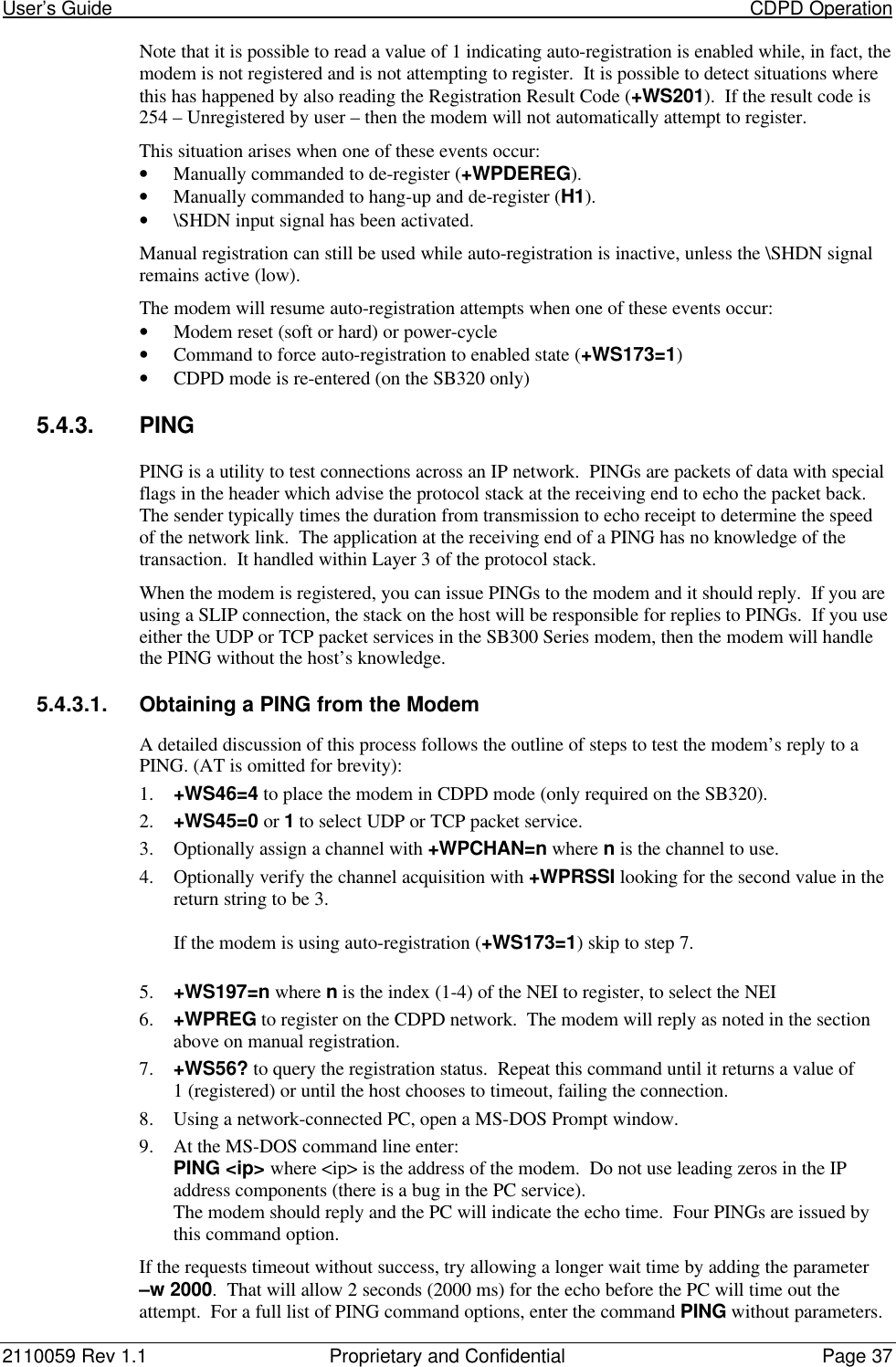
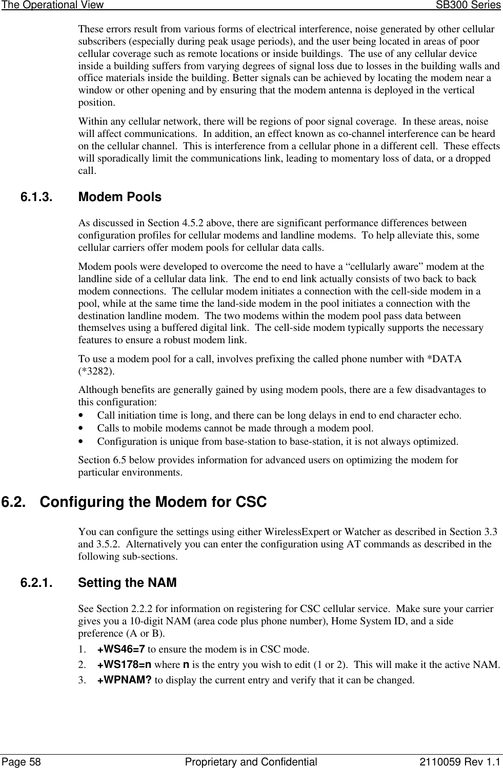
![2110059 Rev 1.1 Proprietary and Confidential Page 8710.4. SB320 SpecificationsPart number 110003310.4.1. Mechanical10.4.1.1. Physical DescriptionThe SB320 comes in a Type III package, andincludes a 30-pin, 0.5mm pitch ZIF connector forthe host interface, a 13-pin I/O connector for the wireline interface, a MMCX connector for theantenna, and a status LED. Dimensions in millimetres are as follows:Figure 10-3: SB320 Physical Dimensions [mm].10.4.1.2. MountingThe SB320 uses an industry standard Type III frame-kit, and as such will fit into PC Card rails.Alternatively, two clips or a bracket may be used to secure the module. There are also twomounting holes provided on either side of the ZIF serial connector.Figure 10-4: SB320 Package Views.](https://usermanual.wiki/General-Dynamics-Itronix/T5200SB300.SB300-Series-User-Guide/User-Guide-49397-Page-98.png)