General Dynamics Itronix T5200SB320 User Manual Manual
General Dynamics Itronix Corporation Manual
UserManual.wiki
>
General Dynamics Itronix
>
T5200SB320 User Manual
SB320 User Guide
Navigation menu
Upload a User Manual
Namespaces
Wiki Guide
HTML
PDF
Info
Views
User Manual
Discussion / Help
Navigation


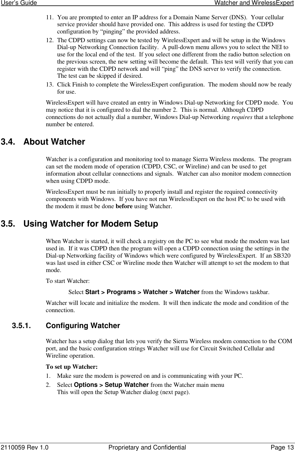


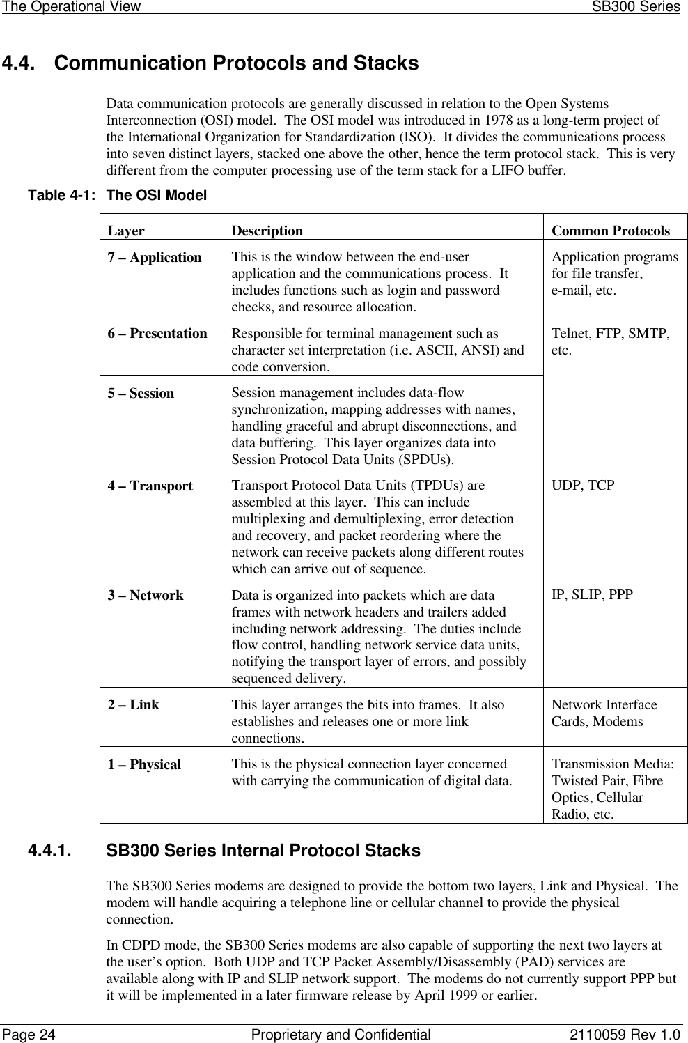


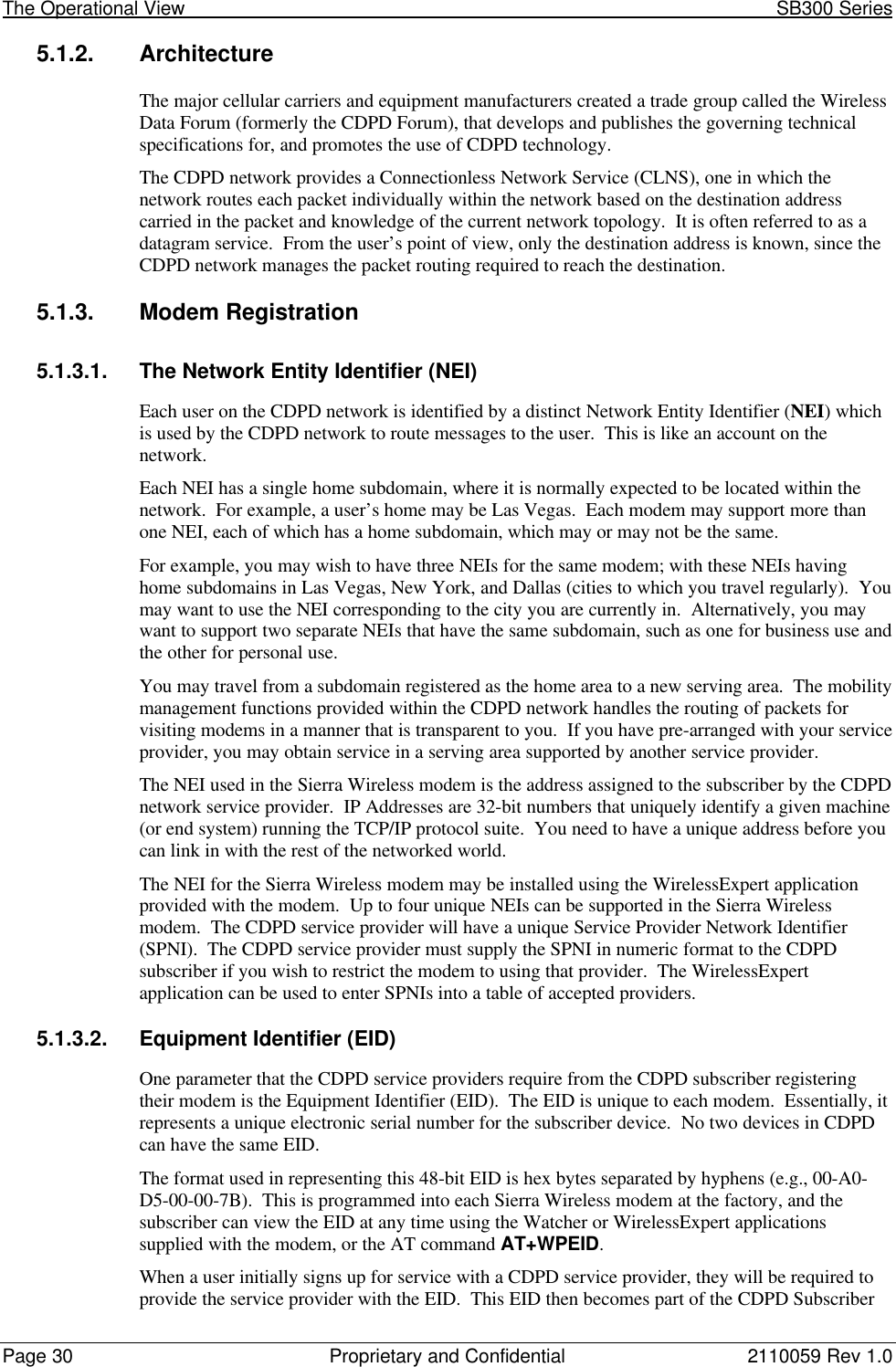
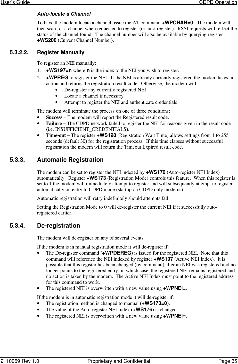
![User’s Guide CDPD Operation2110059 Rev 1.0 Proprietary and Confidential Page 335. +WS174=n where n indicates the channel side preference. Values are:0 – A side preferred,1 – B side preferred,2 – A side only,3 – B side only.NOTE that this preference is stored in a register not associated with a particular entry in theNEI table. The preference will be used for all NEI registrations.5.2.2. SPNI MatchingIf you want to restrict the modem to only using channels belonging to a particular list of serviceproviders you can enter a table of SPNI values. When the modem is finding a channel, it willcheck the SPNI of each channel against entries in this table. If there is no match, the modem willreject the channel and continue searching.If the table is empty, the SPNI matching feature is disabled.NOTE: If you set SPNI matching and also use +WPCHAN to assign a channel manually, theassigned channel will not lock if the SPNI fails to match. The modem will not be able to registerbecause it will not look for another channel if you have manually set a channel. The channel lockcan be checked using +WPRSSI.5.2.2.1. SPNI Table ConfigurationTo manage the use of SPNI matching using AT Commands enter the following commands (theAT is omitted for brevity):Read the Current SPNI Table1. +WPSPNI? Displays the SPNI Table. If the table is empty then SPNI matching is disabled.If there is at least one entry then SPNI matching is enabled.Disable SPNI Matching1. +WPSPNI= By not entering parameters, the table will be erased. An empty table disablesSPNI matching.Enable SPNI Matching1. +WPSPNI=n[,n[,…n]] where n is a SPNI value and multiple values are separated bycommas. The list of parameters provided will replace any previous table. You cannot appendentries to an existing table. You may enter up to 10 values in the table. By entering one ormore SPNI values, the SPNI matching feature is automatically enabled.5.3. CDPD Network RegistrationNote that network registration must be performed before communication across the network canbegin. Registering on the network is distinct from opening a session. Registration simplyconfirms a connection to the network as a whole and authenticates your modem’s credentials.Data Carrier Detect (DCD) is tied to sessions not network registration. A session does not beginuntil you originate a session (client) or auto-answer one (server).The modem can be set to register manually (on command) or automatically when it enters CDPDmode. The NEI address used for registration is determined differently for each method.The mode of registration is set in register +WS173 (Registration Mode). A value of 0 indicatesmanual registration and 1 indicates automatic. The modem is shipped with a value of 1 but themodem will always default to the last method used. Restoring settings with &F (factory) orZ (user profile) will NOT restore a setting to this register.For WirelessExpert to work, the modem must be set to automatic registration.](https://usermanual.wiki/General-Dynamics-Itronix/T5200SB320/User-Guide-49410-Page-45.png)
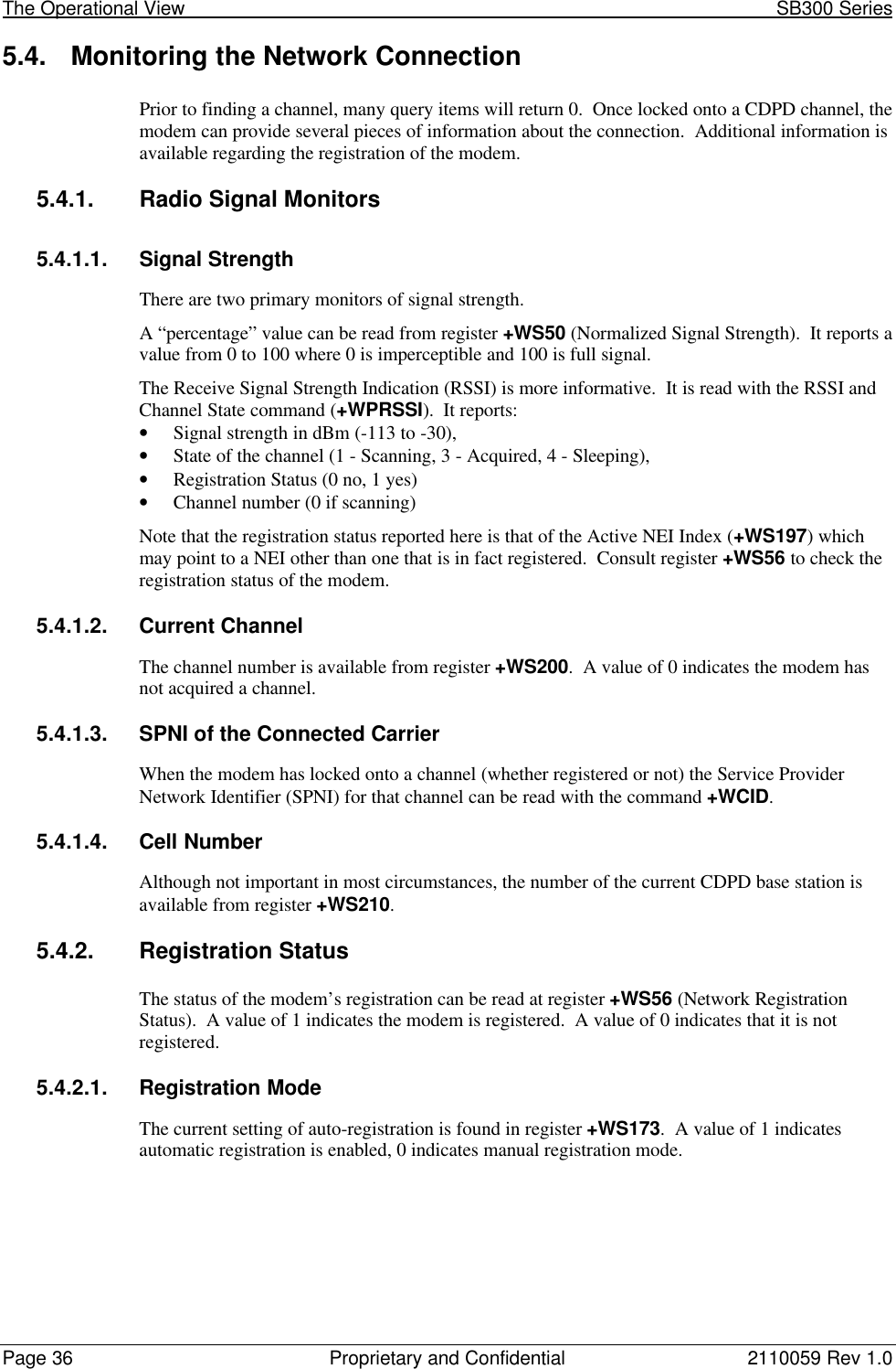
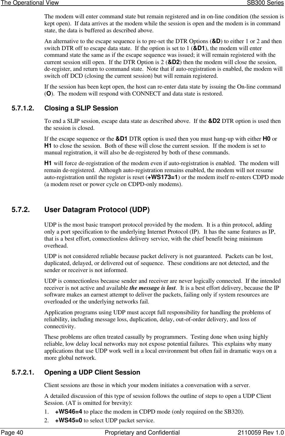

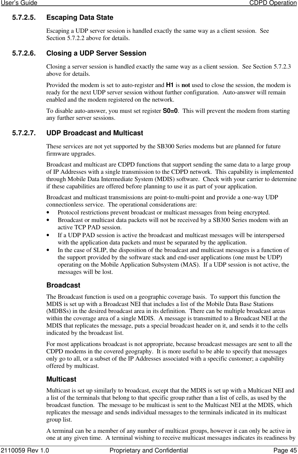


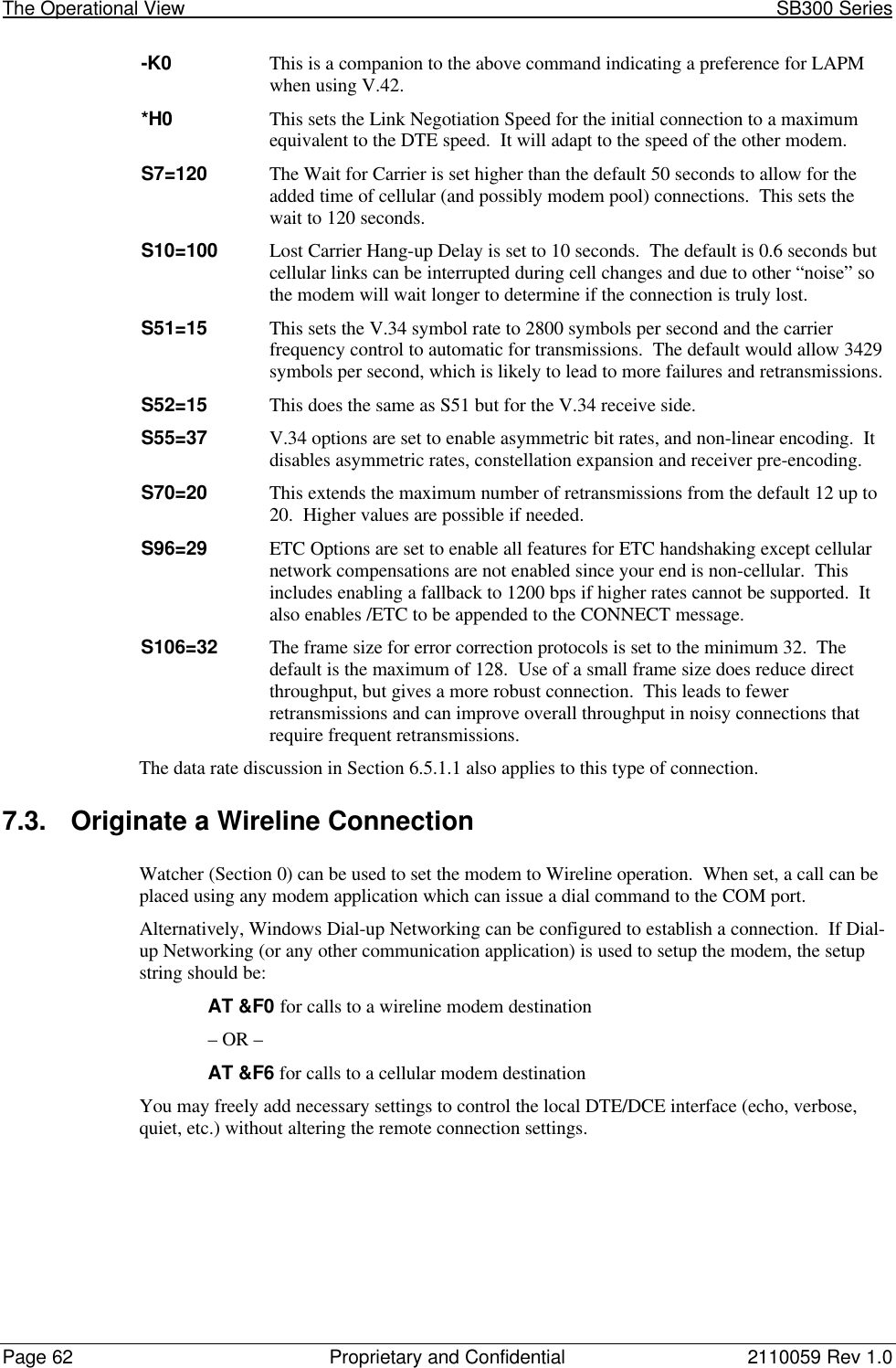


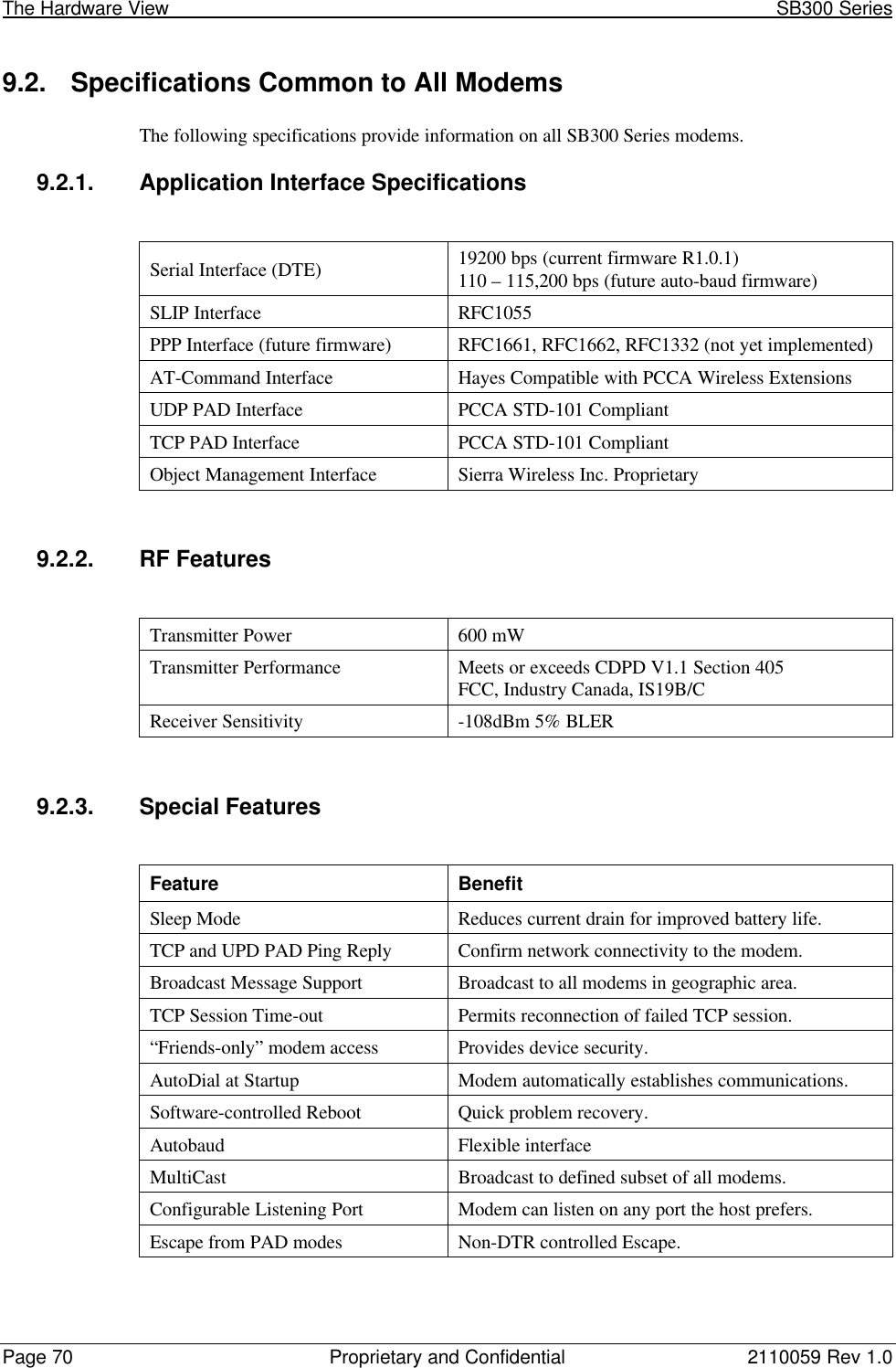

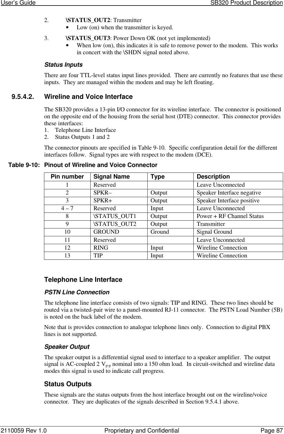
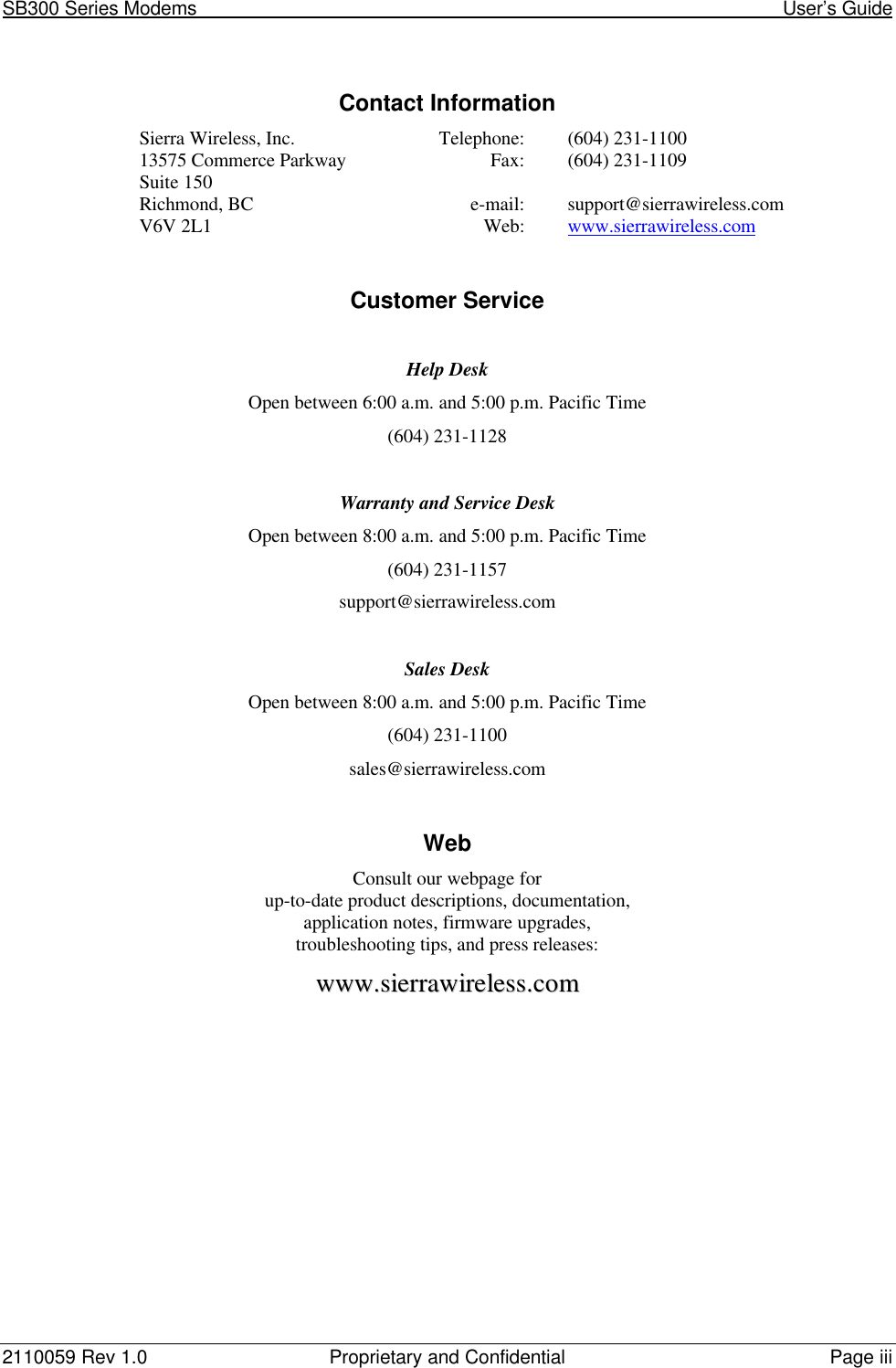
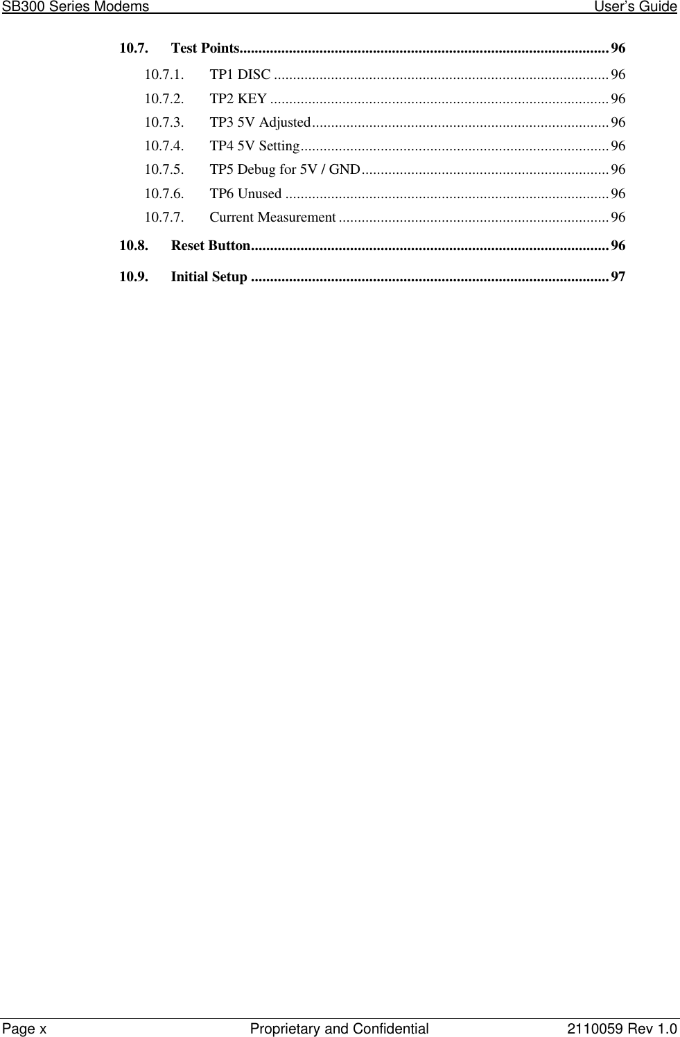
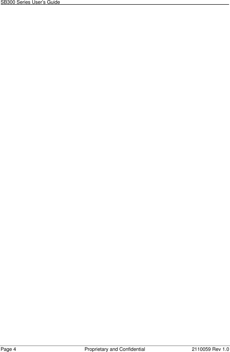
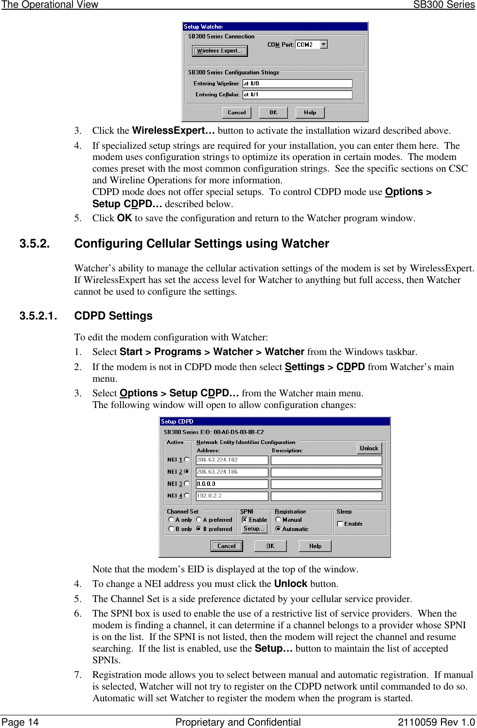
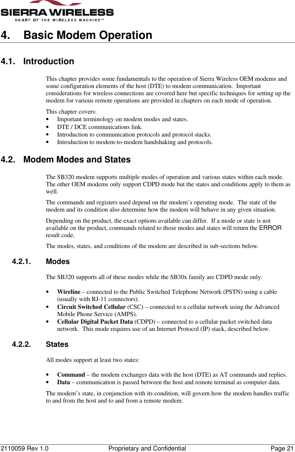
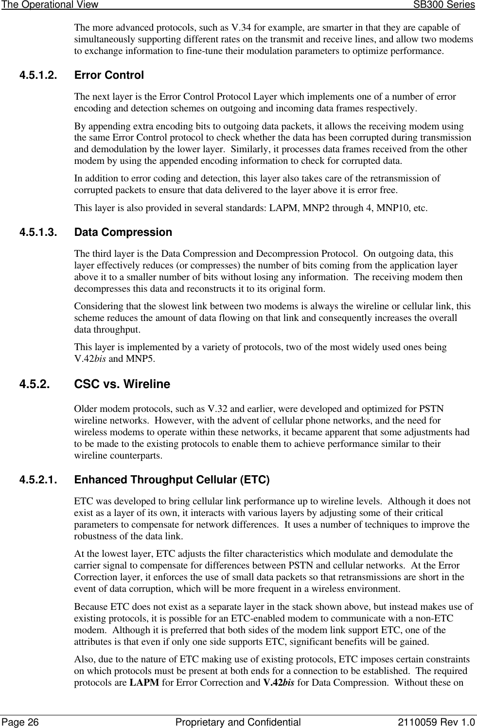
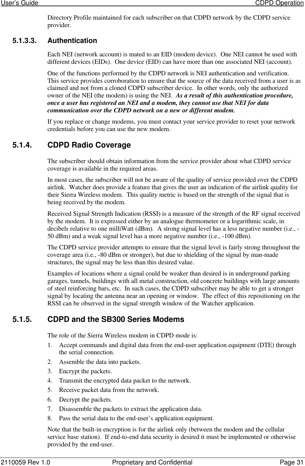
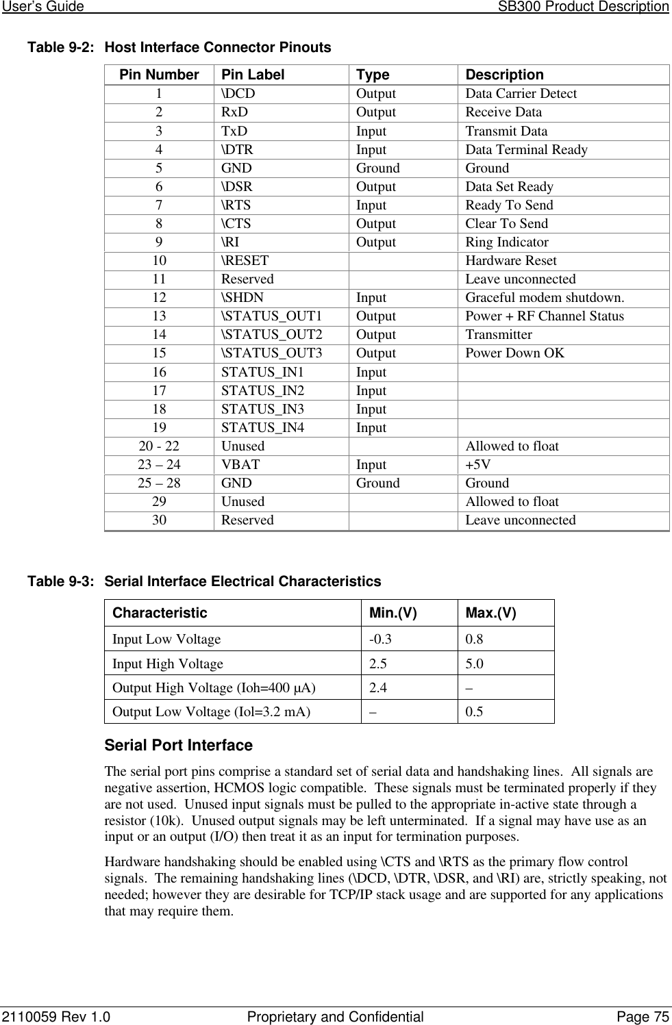
![2110059 Rev 1.0 Proprietary and Confidential Page 739.3. SB300 CDPD ModemPart number 11000349.3.1. Mechanical9.3.1.1. Physical DescriptionThe SB300 comes in a Type III package, and includes a30-pin, 0.5mm pitch ZIF connector for the host interface,a MMCX connector for the antenna, and a status LED. Dimensions (in mm) are as follows:Figure 9-1: SB300 Physical Dimensions [mm].9.3.1.2. MountingThe SB300 uses an industry standard Type III frame-kit, and as such will fit into PC Card rails.Alternatively, two clips or a bracket may be used to secure the module. There are also twomounting holes provided on either side of the ZIF serial connector.Figure 9-2: SB300 Package Views.](https://usermanual.wiki/General-Dynamics-Itronix/T5200SB320/User-Guide-49410-Page-85.png)

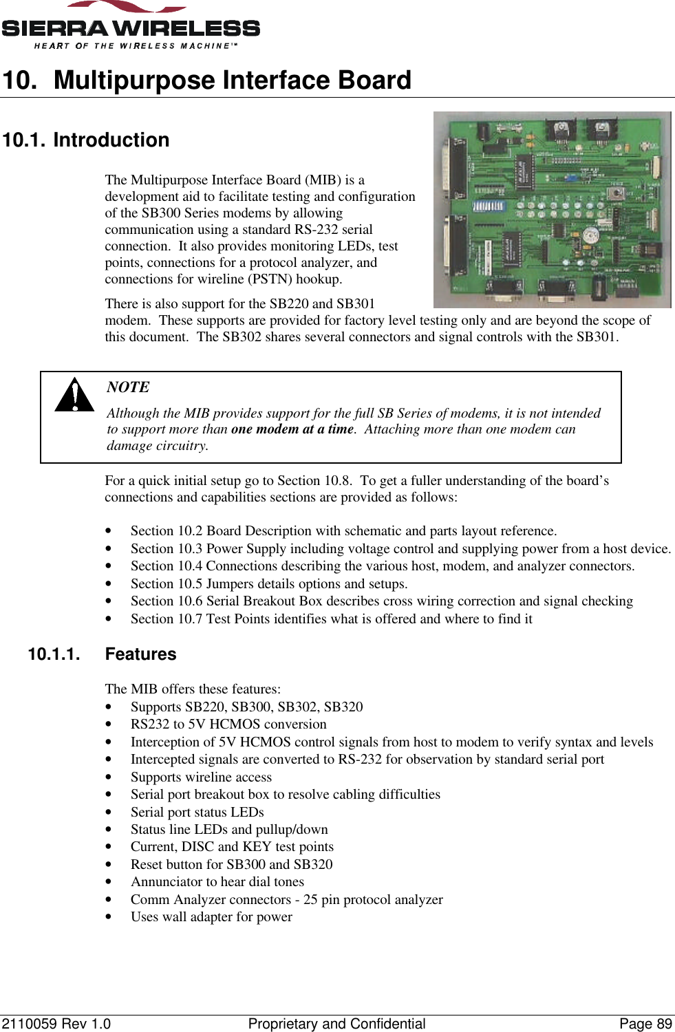
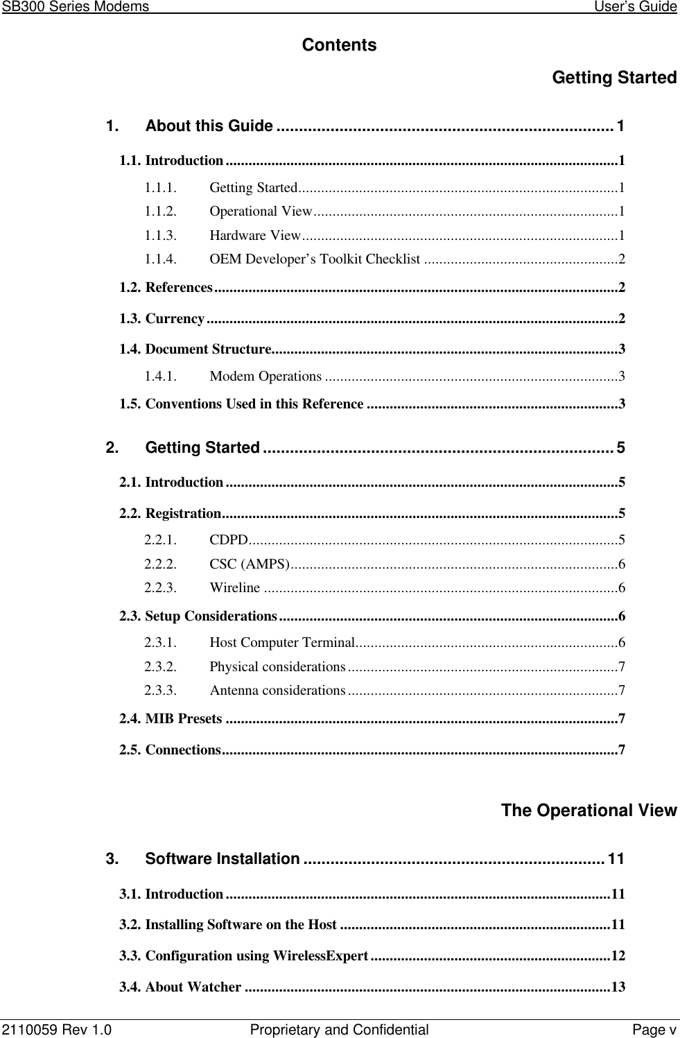
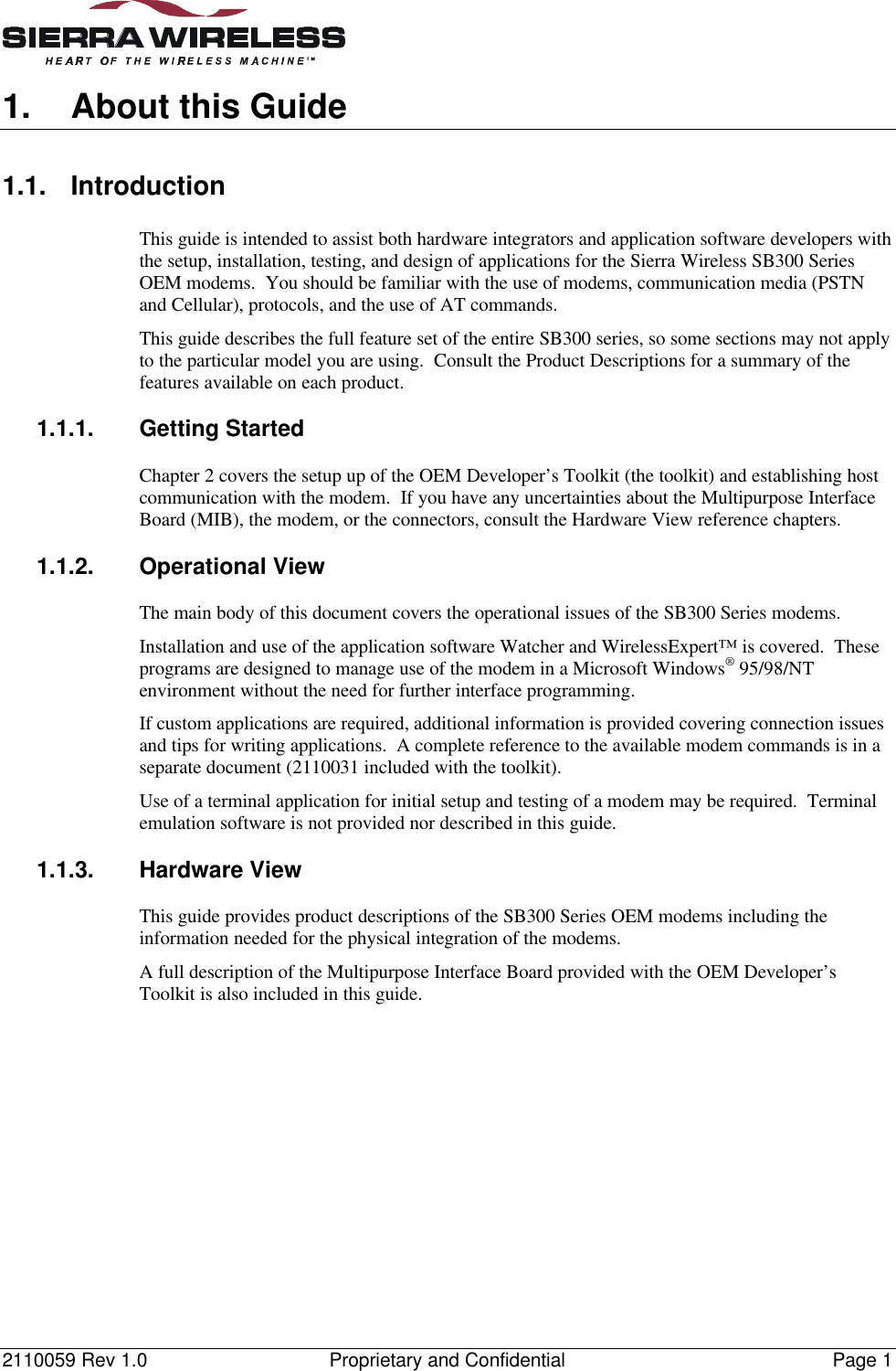
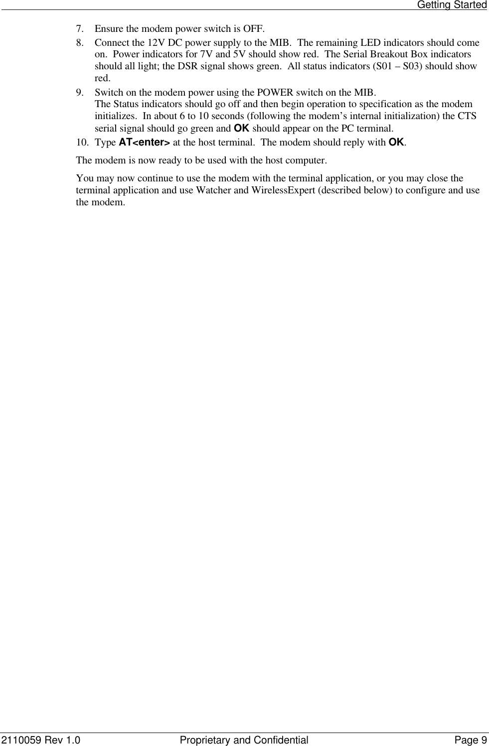
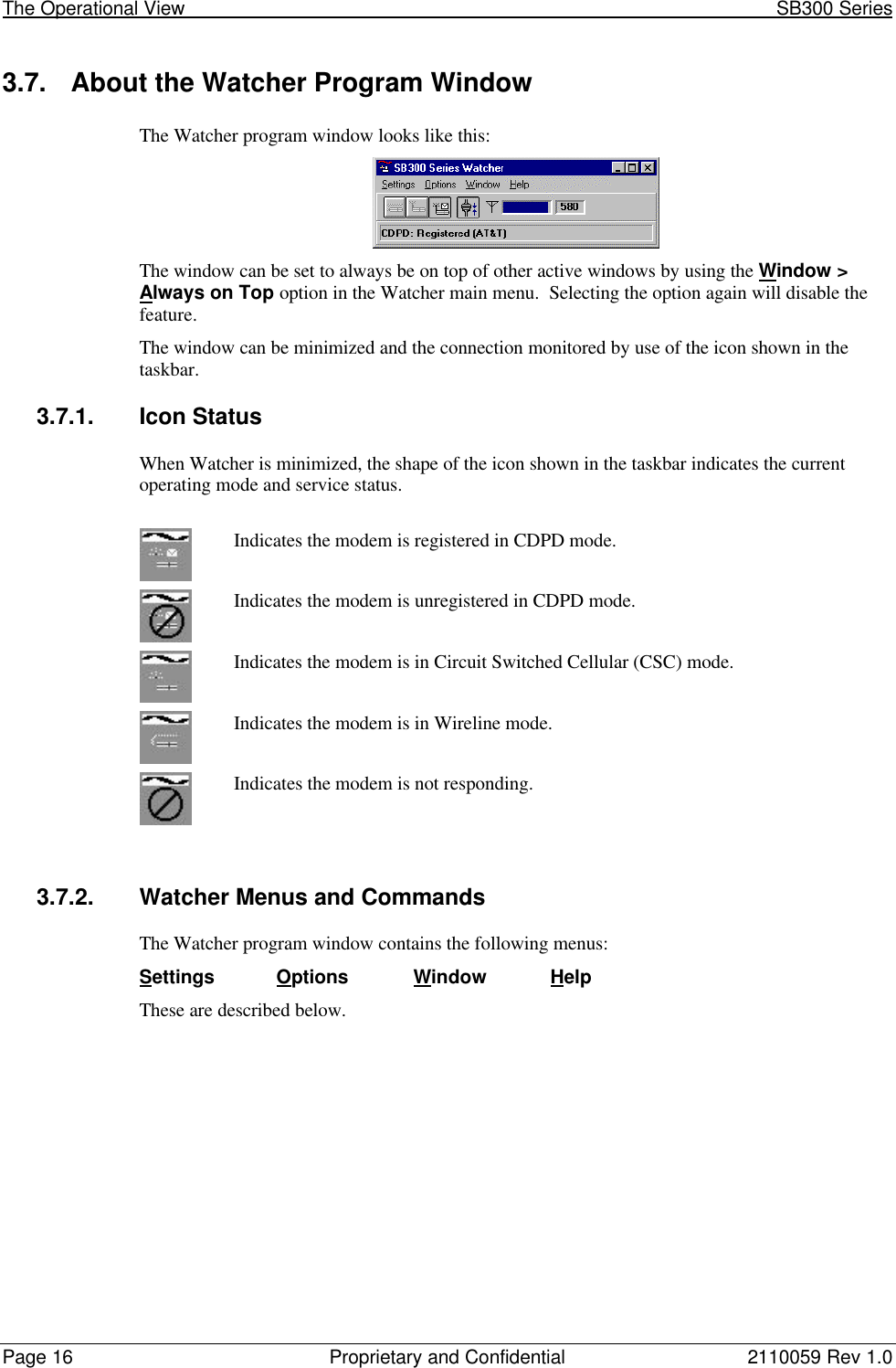
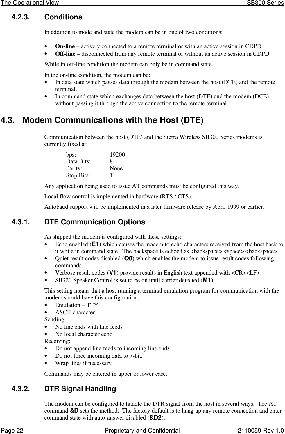
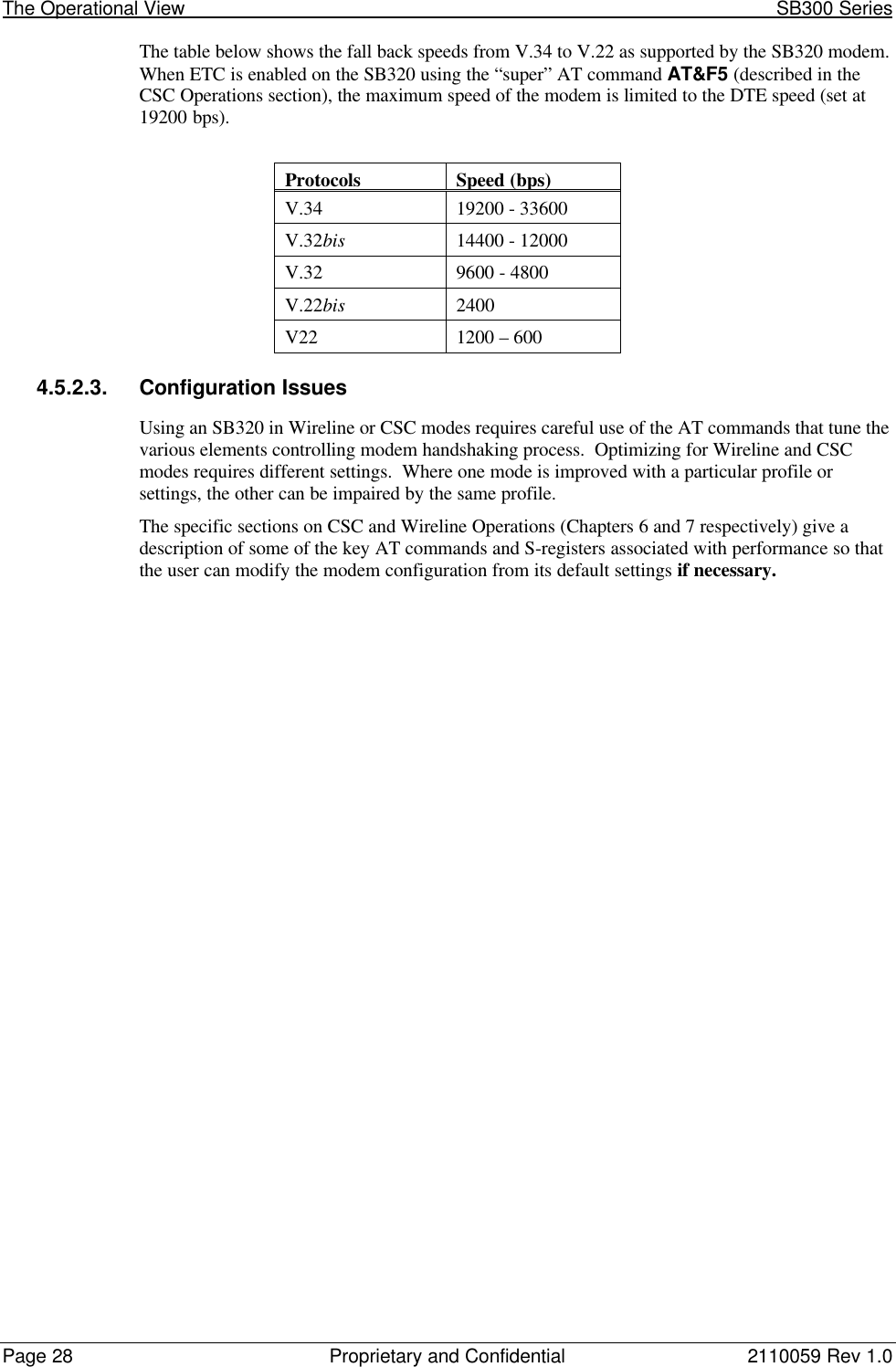
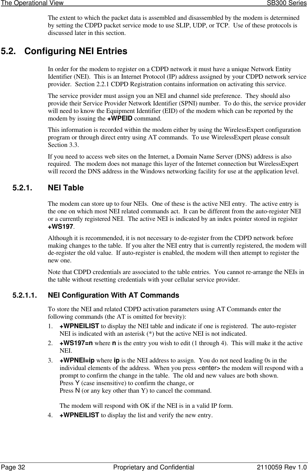
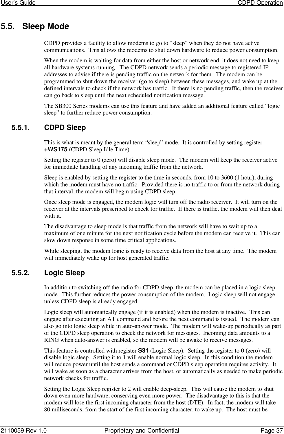
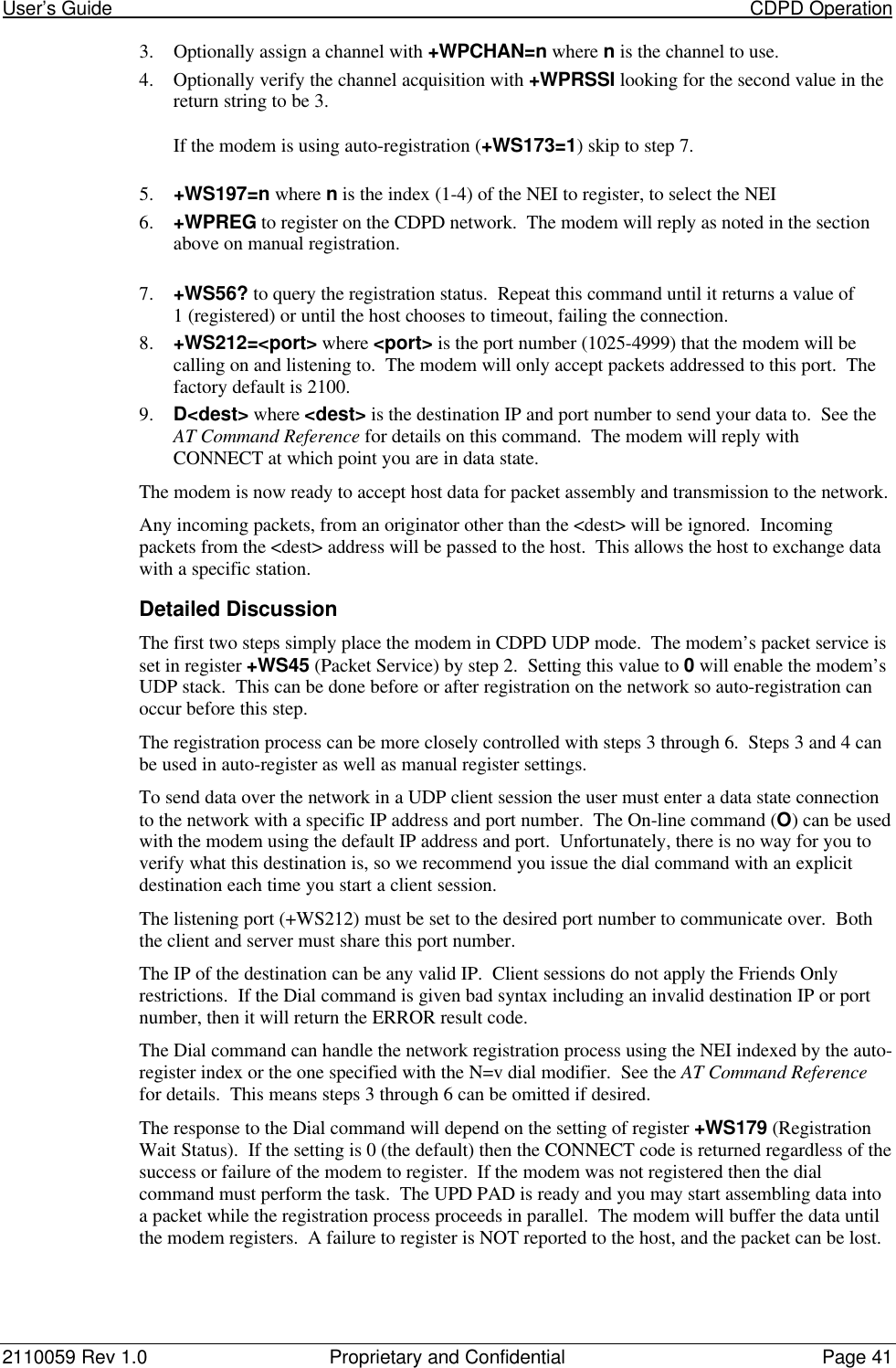
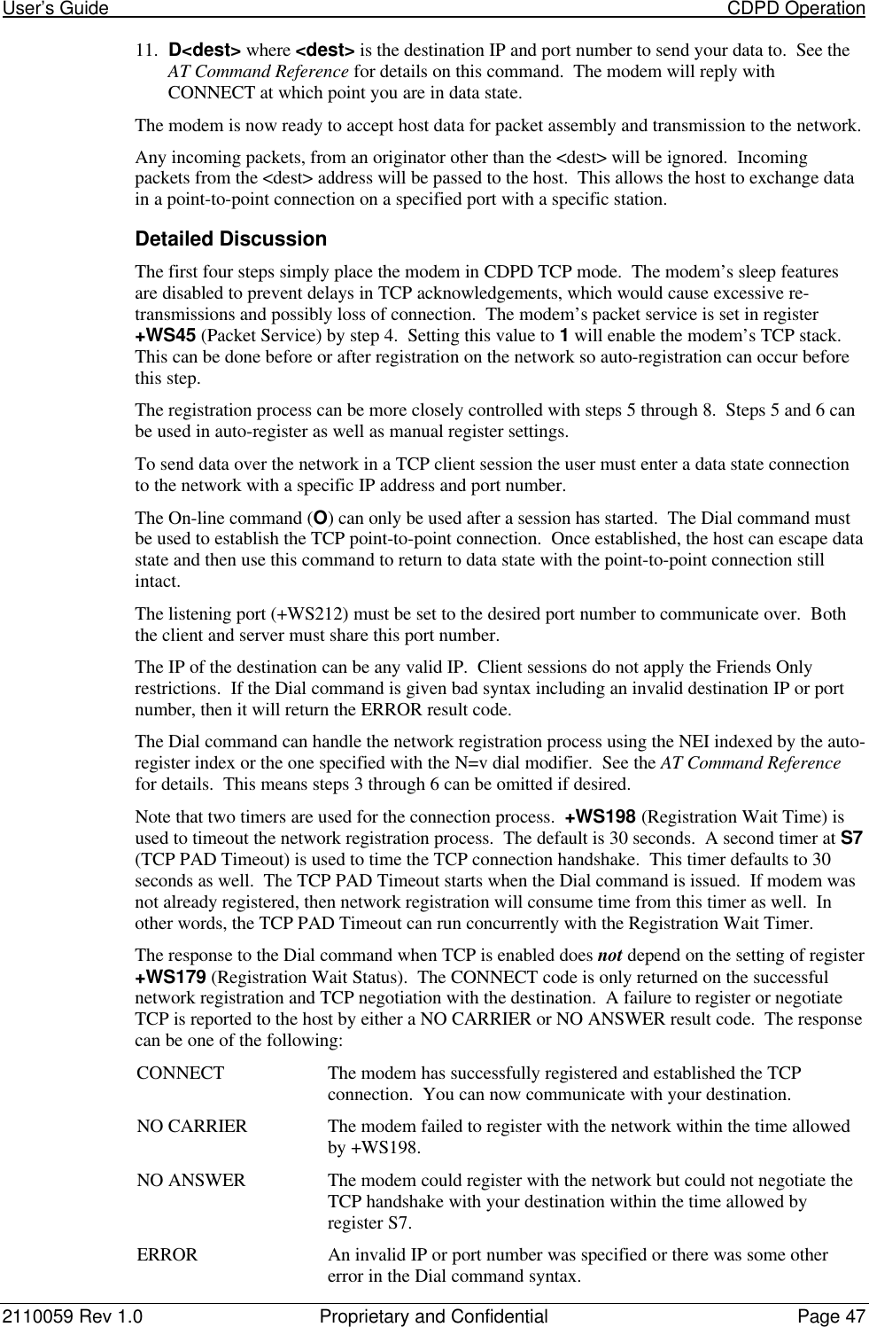
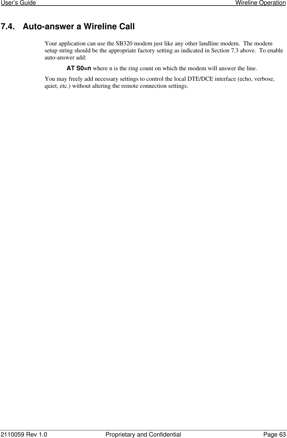
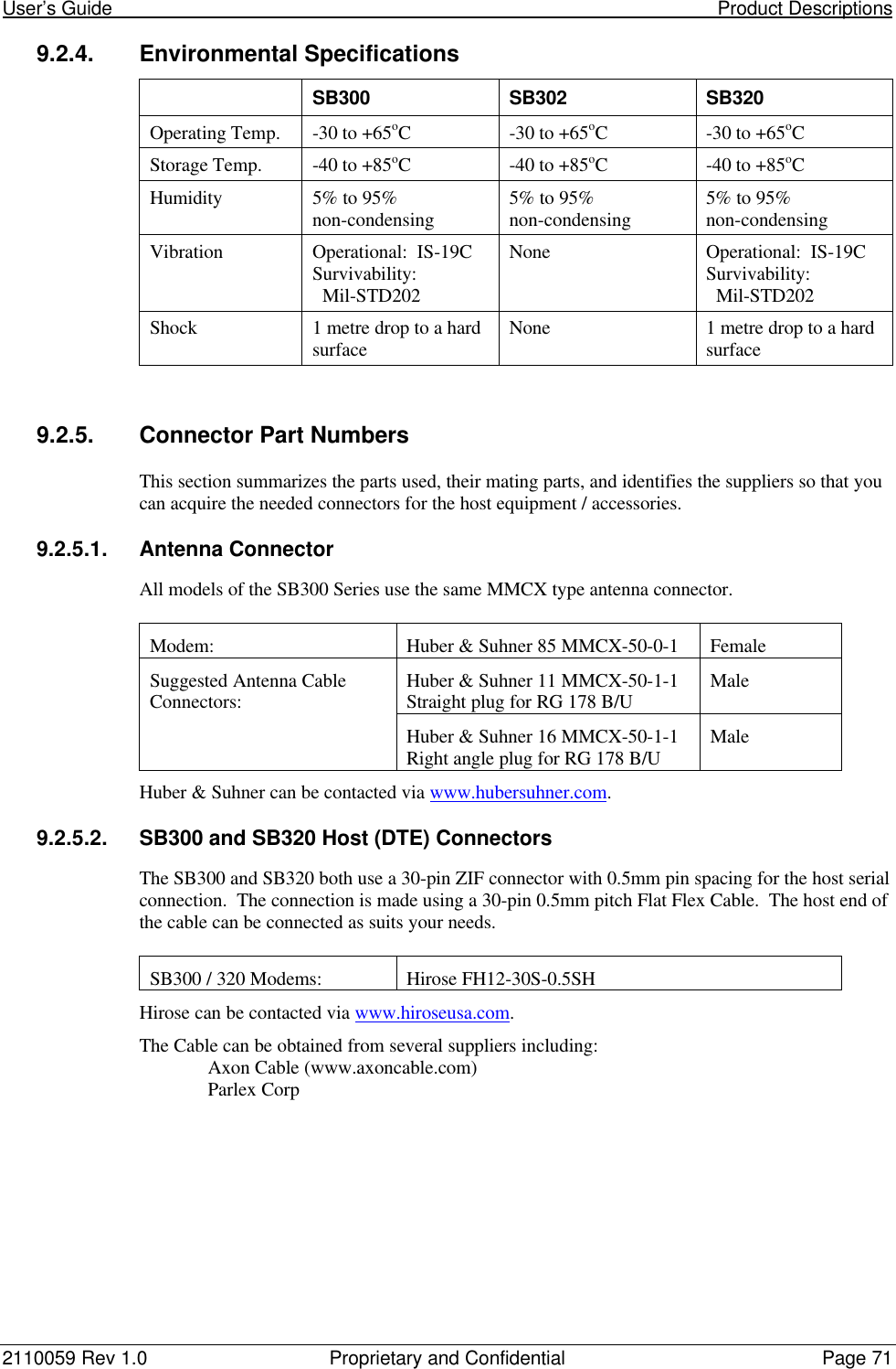
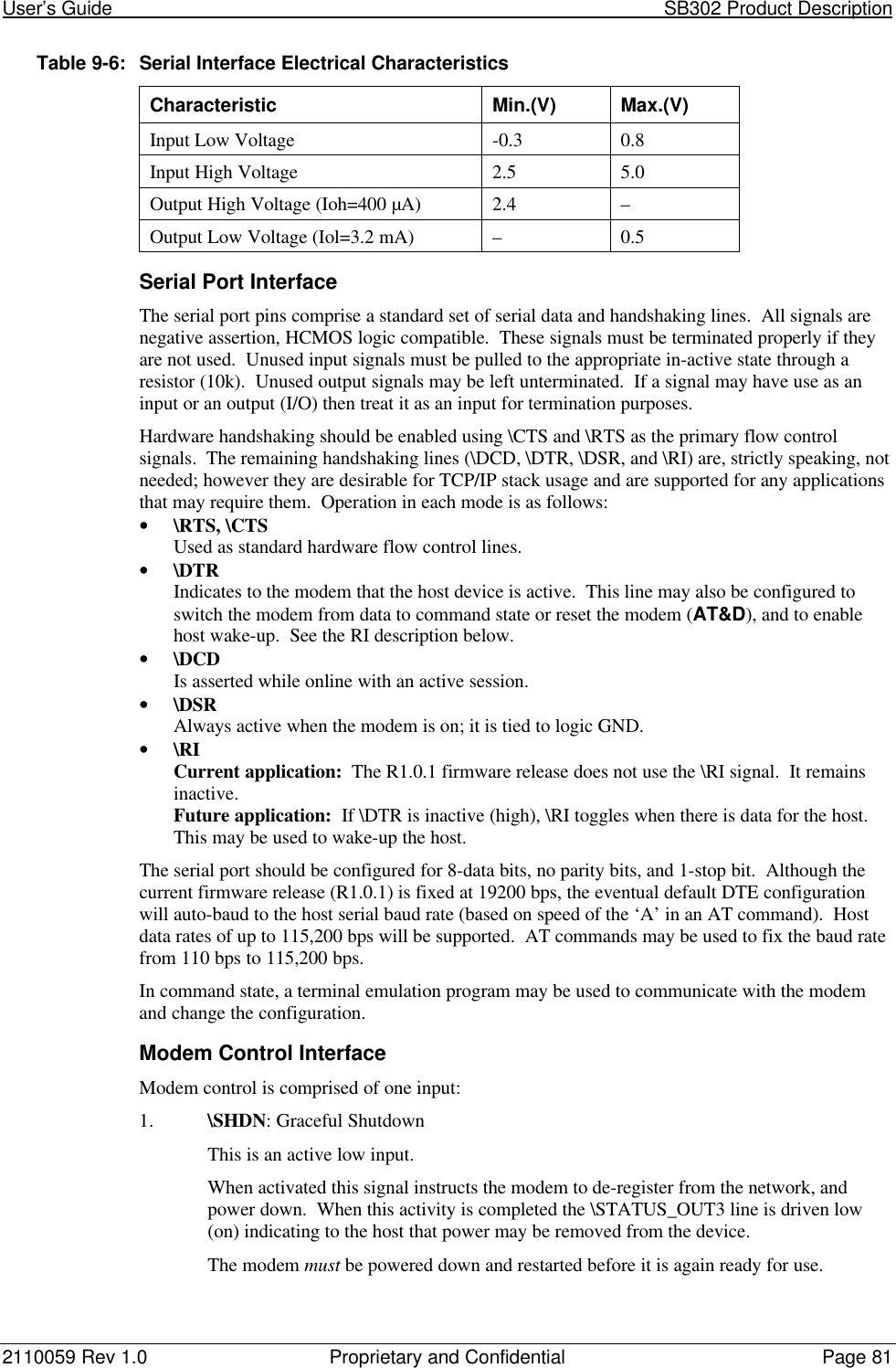
![2110059 Rev 1.0 Proprietary and Confidential Page 799.4. SB302 SpecificationsPart number 11000439.4.1. Mechanical9.4.1.1. Physical DescriptionThe SB302 comes as a board stack of two circuitboards. It includes a 16-pin, 0.1” dual-row header forthe host interface and an MMCX style RF connector for the antenna. Dimensions in millimetresare as follows:Figure 9-3: Physical dimensions shown in inches [mm]. Figure 9-4: Assembly View.9.4.2. ConnectorsSee Section 9.2.5 for part number and manufacturer contact details on all connections.9.4.2.1. Antenna ConnectorThe SB302 provides an MMCX type RF connector for the antenna connection. For propermatching the antenna should be 50 ohms with a return loss of 10 dB or better between824 - 894 MHz. System antenna gain should be 0 dB.](https://usermanual.wiki/General-Dynamics-Itronix/T5200SB320/User-Guide-49410-Page-91.png)

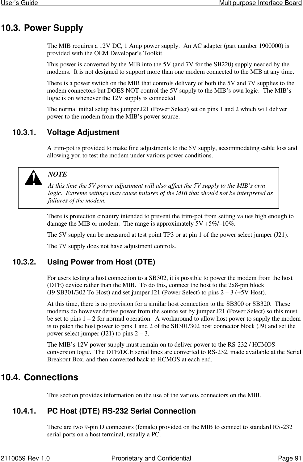
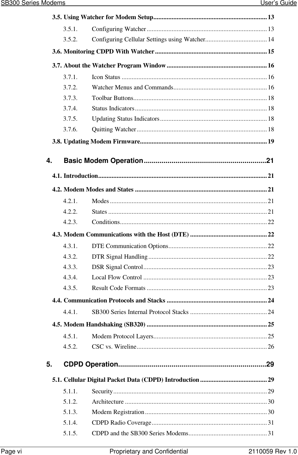
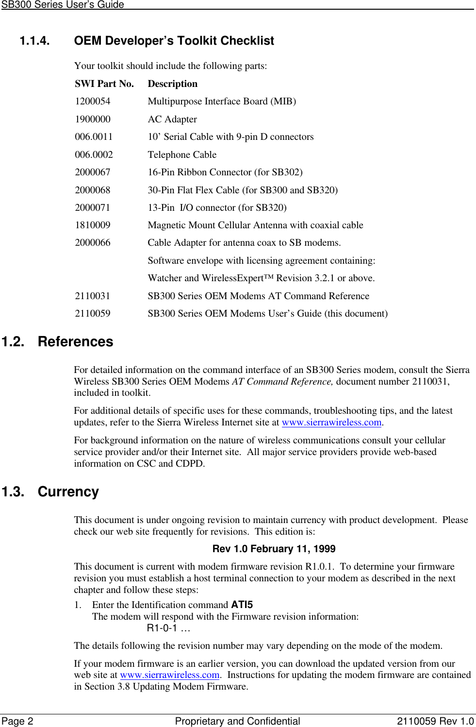
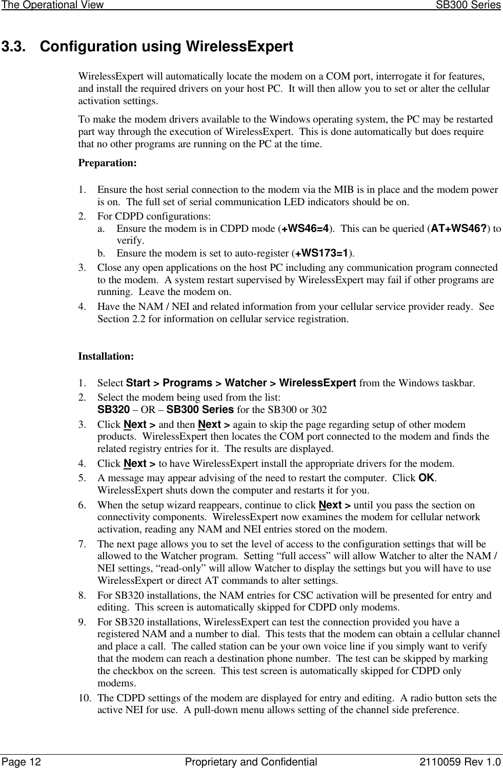
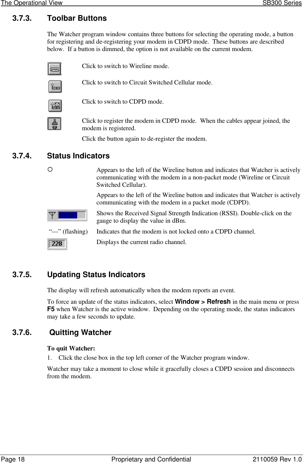
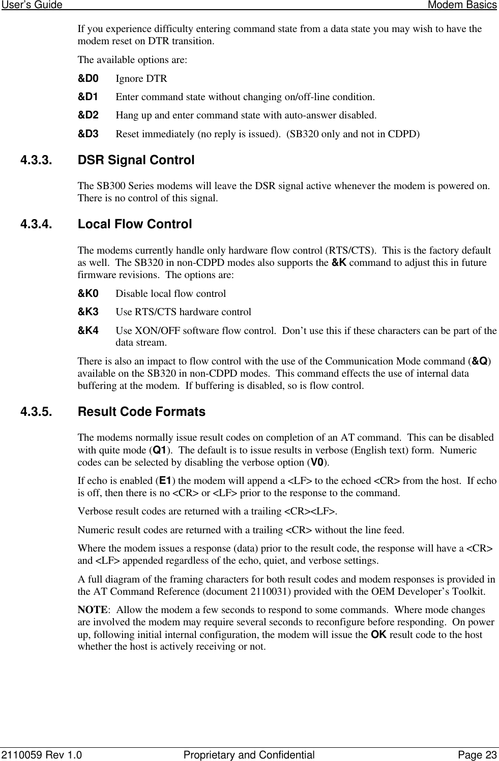
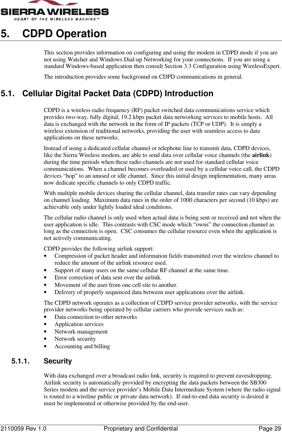
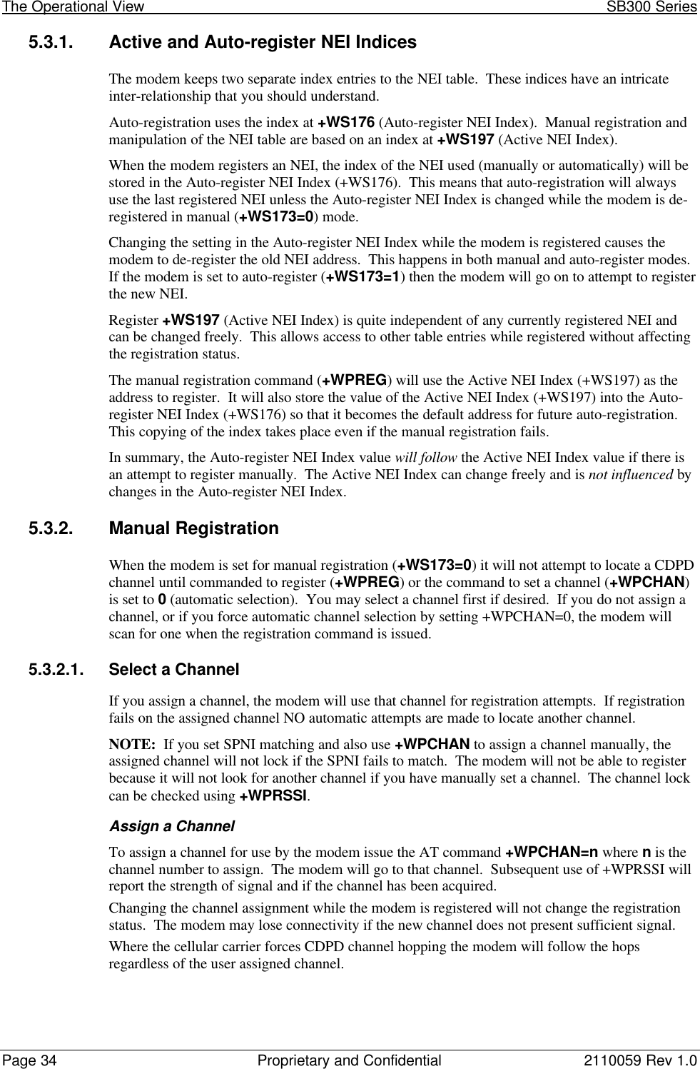
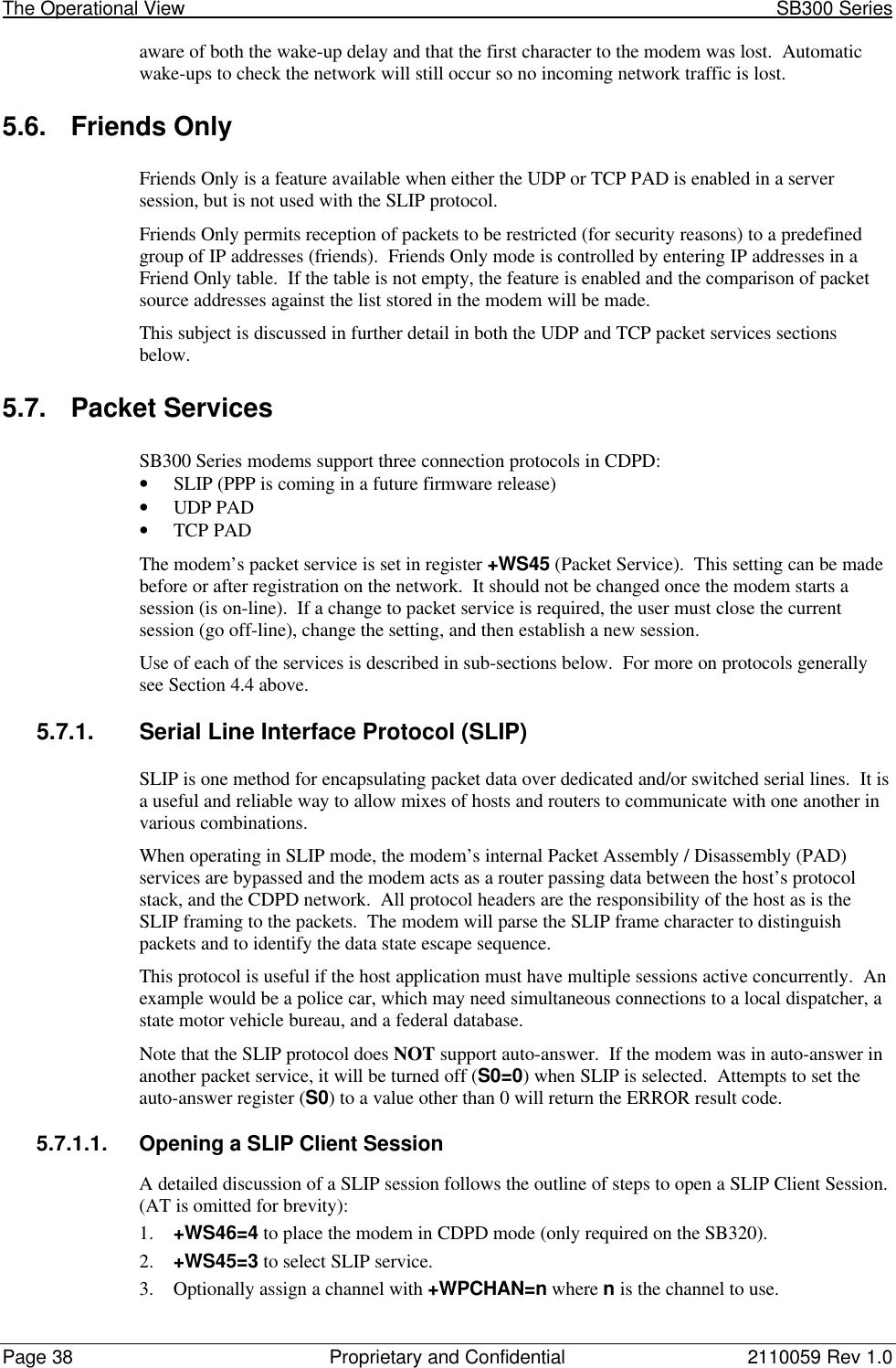
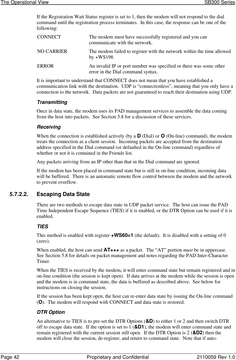
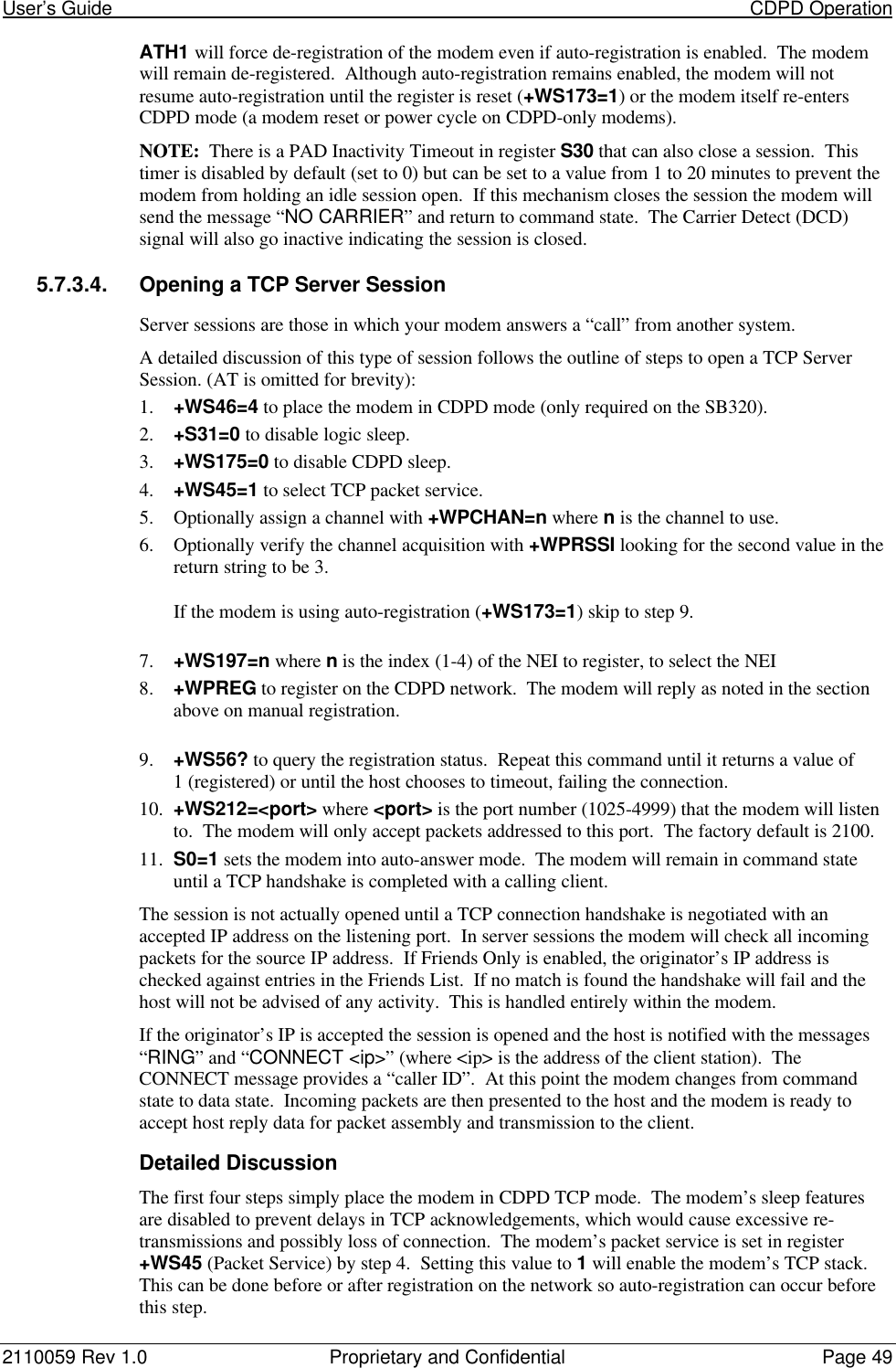
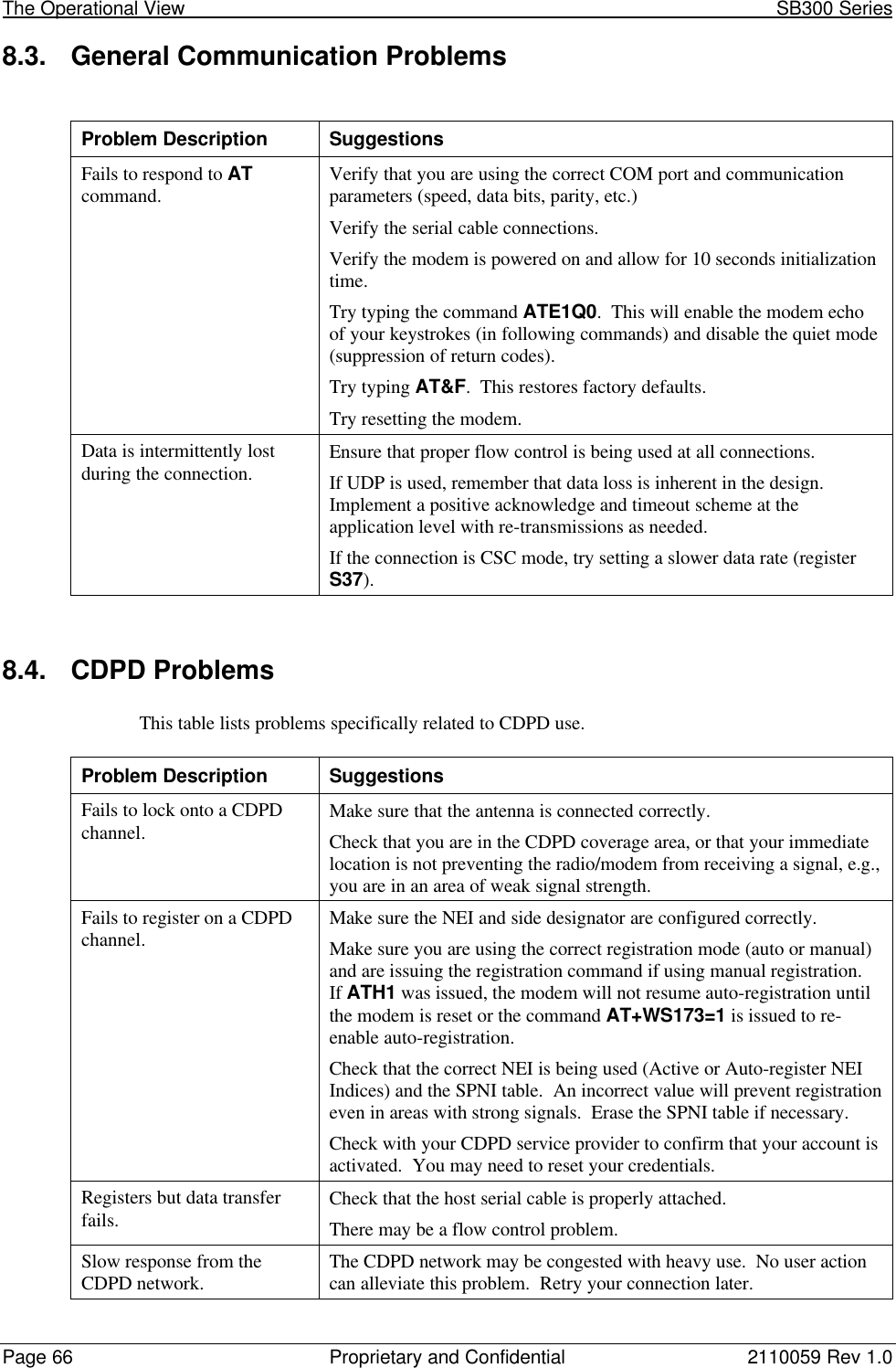
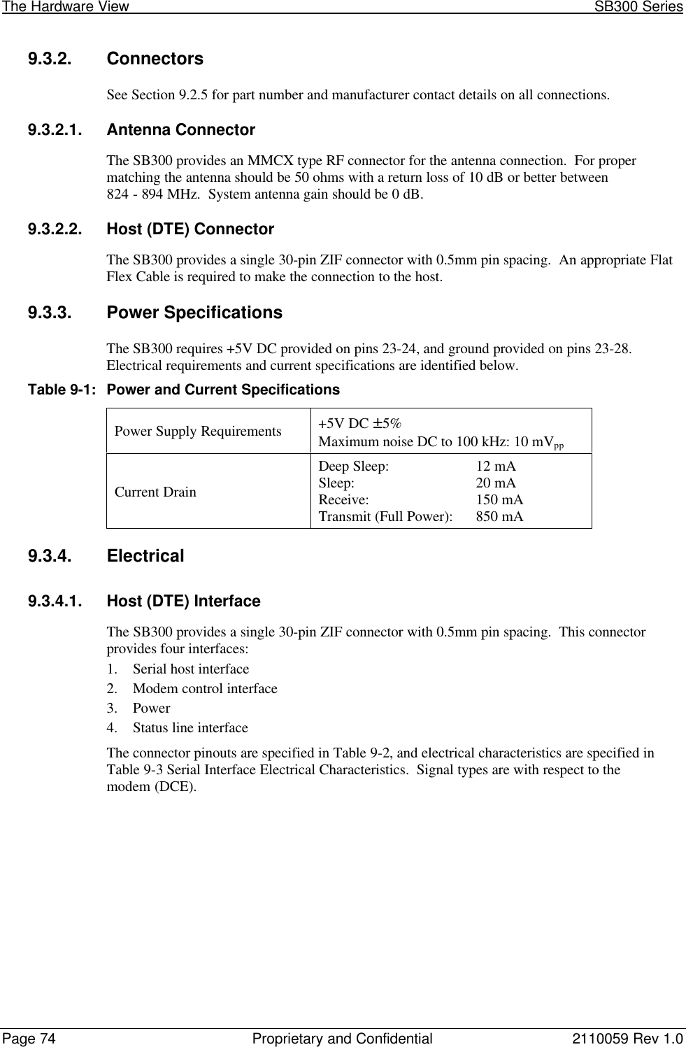
![2110059 Rev 1.0 Proprietary and Confidential Page 839.5. SB320 SpecificationsPart number 11000339.5.1. Mechanical9.5.1.1. Physical DescriptionThe SB320 comes in a Type III package, and includesa 30-pin, 0.5mm pitch ZIF connector for the hostinterface, a 13-pin I/O connector for the wirelineinterface, a MMCX connector for the antenna, and a status LED. Dimensions in millimetres are asfollows:Figure 9-5: SB320 Physical Dimensions [mm].9.5.1.2. MountingThe SB320 uses an industry standard Type III frame-kit, and as such will fit into PC Card rails.Alternatively, two clips or a bracket may be used to secure the module. There are also twomounting holes provided on either side of the ZIF serial connector.Figure 9-6: SB320 Package Views.](https://usermanual.wiki/General-Dynamics-Itronix/T5200SB320/User-Guide-49410-Page-95.png)