General Dynamics Mission Systems AD510 Iridium Satellite Transceiver Active Antenna User Manual Active Antenna
General Dynamics C4 Systems Iridium Satellite Transceiver Active Antenna Active Antenna
UserManual.wiki
>
General Dynamics Mission Systems
>
AD510 User Manual
Users Manual
Navigation menu
Upload a User Manual
Namespaces
Wiki Guide
HTML
PDF
Info
Views
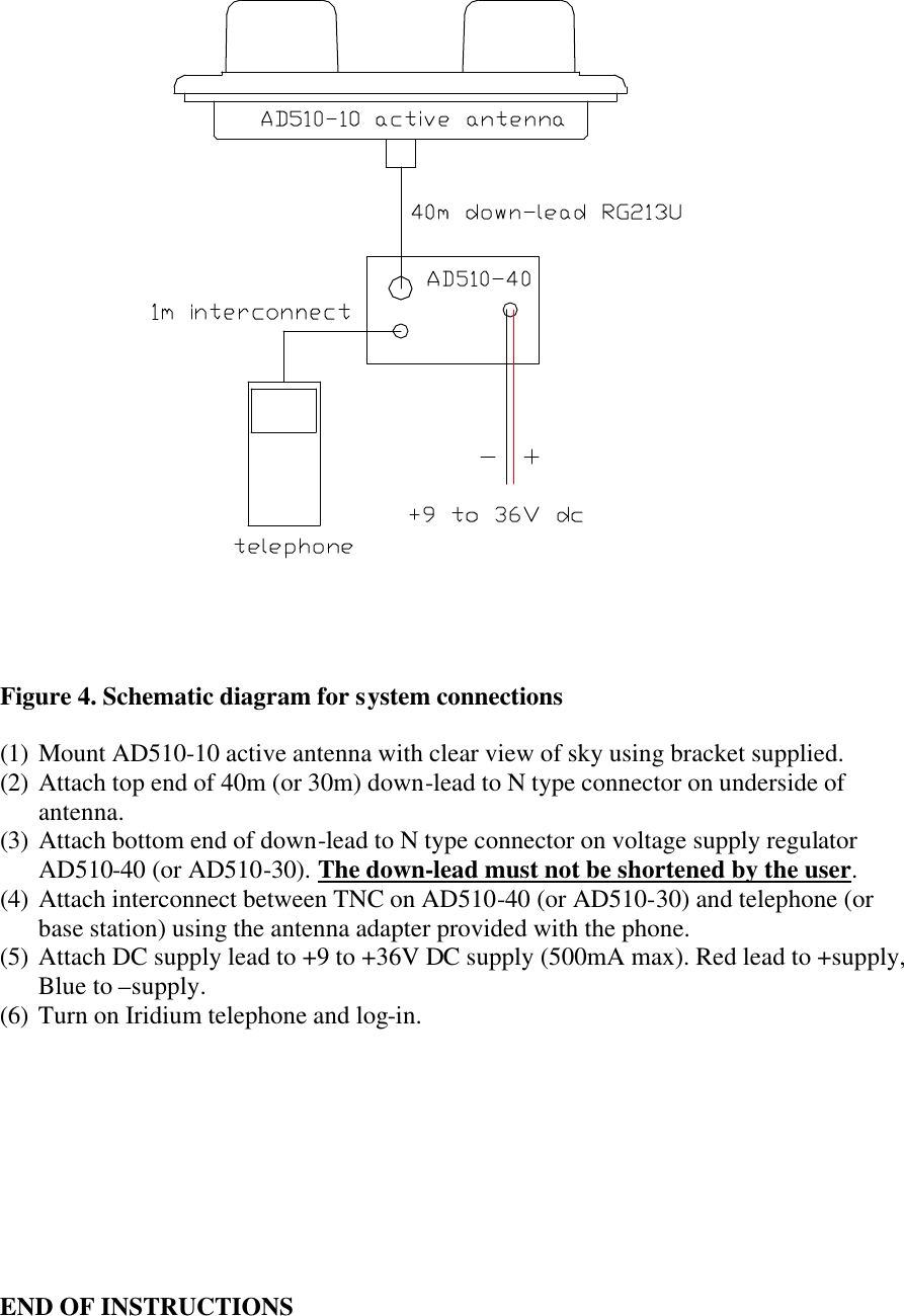
User Manual
Discussion / Help
Navigation