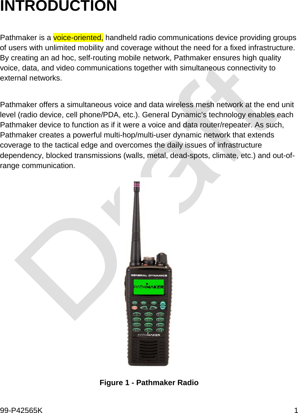
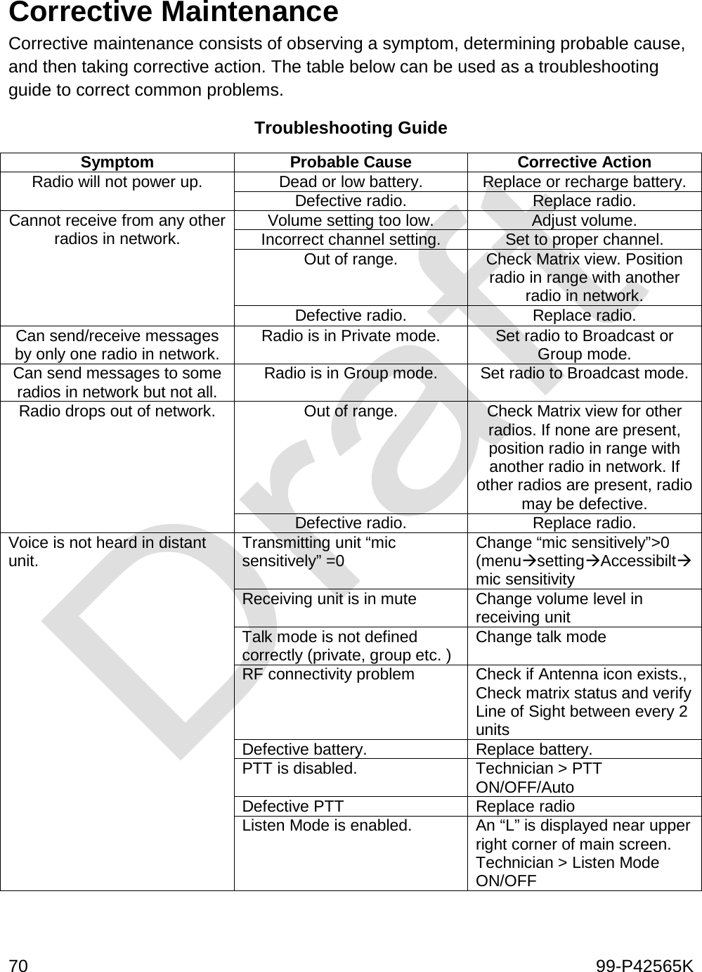
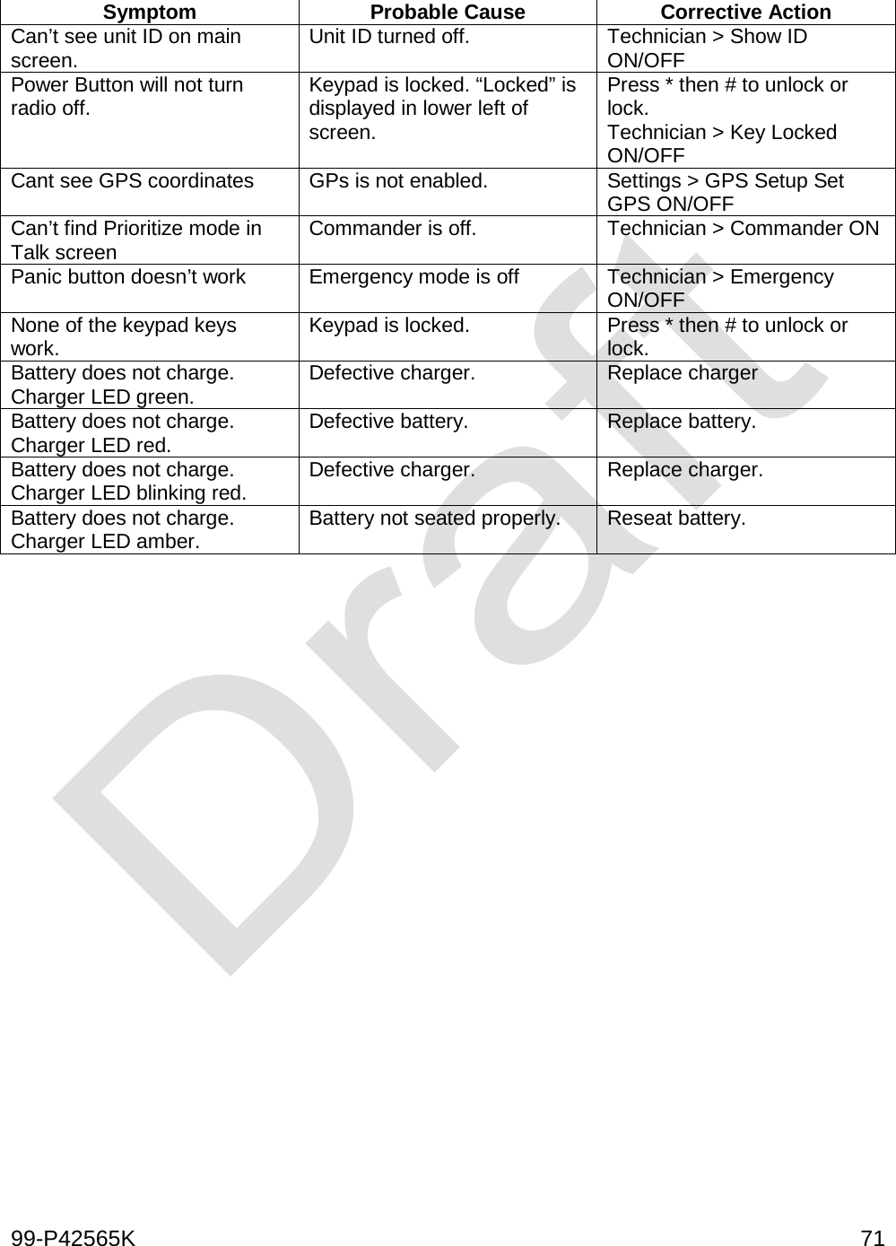
General Dynamics Mission Systems PNR-1000 PathMaker Network Radio User Manual 1
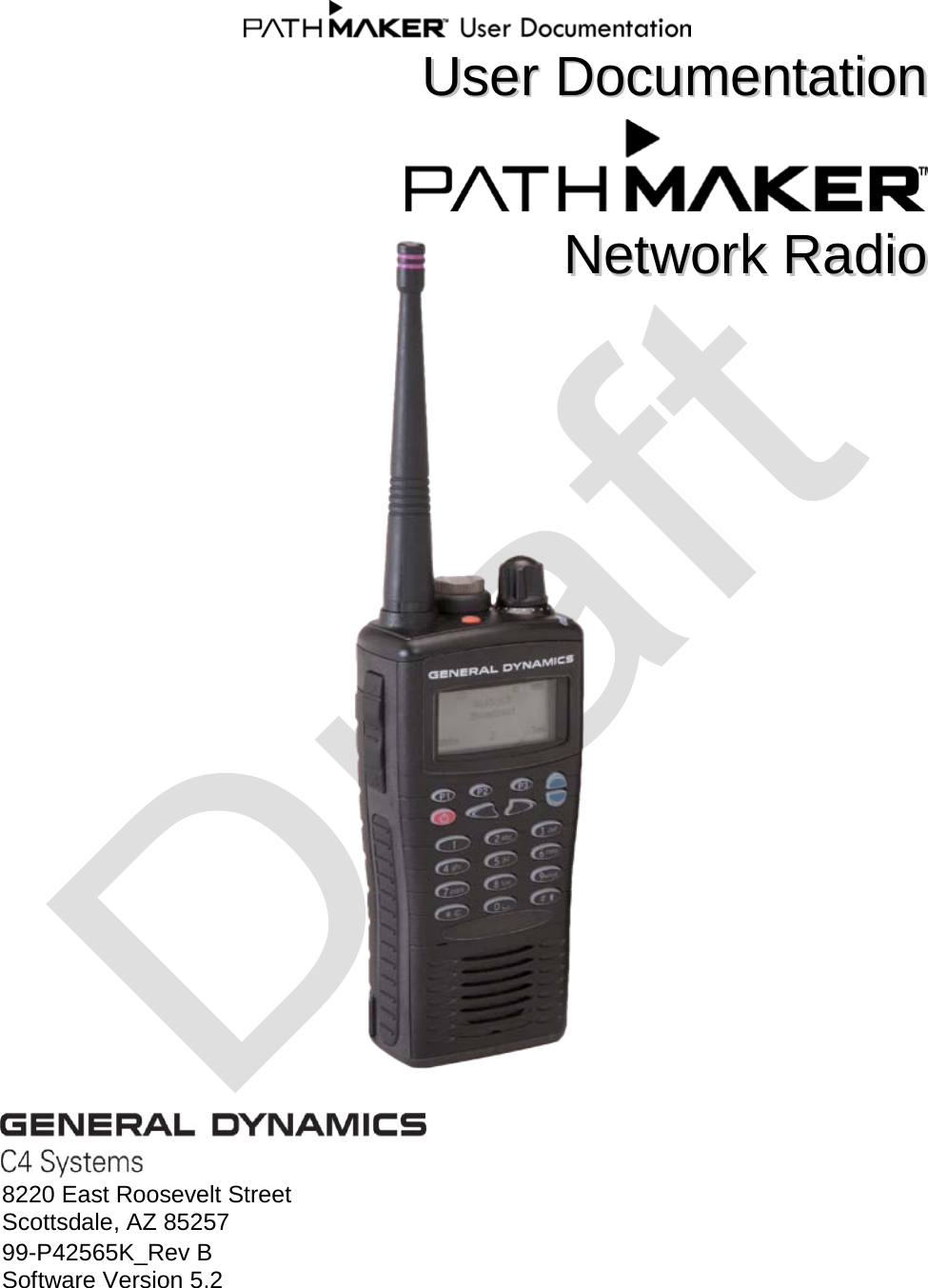
General Dynamics C4 Systems PathMaker Network Radio 1
UserManual.wiki
>
General Dynamics Mission Systems
>
PNR 1000 User Manual
Exhibit 8 Users Manual (Draft)
Navigation menu
Upload a User Manual
Namespaces
Wiki Guide
HTML
PDF
Info
Views
User Manual
Discussion / Help
Navigation
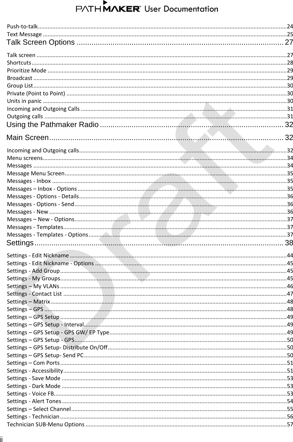
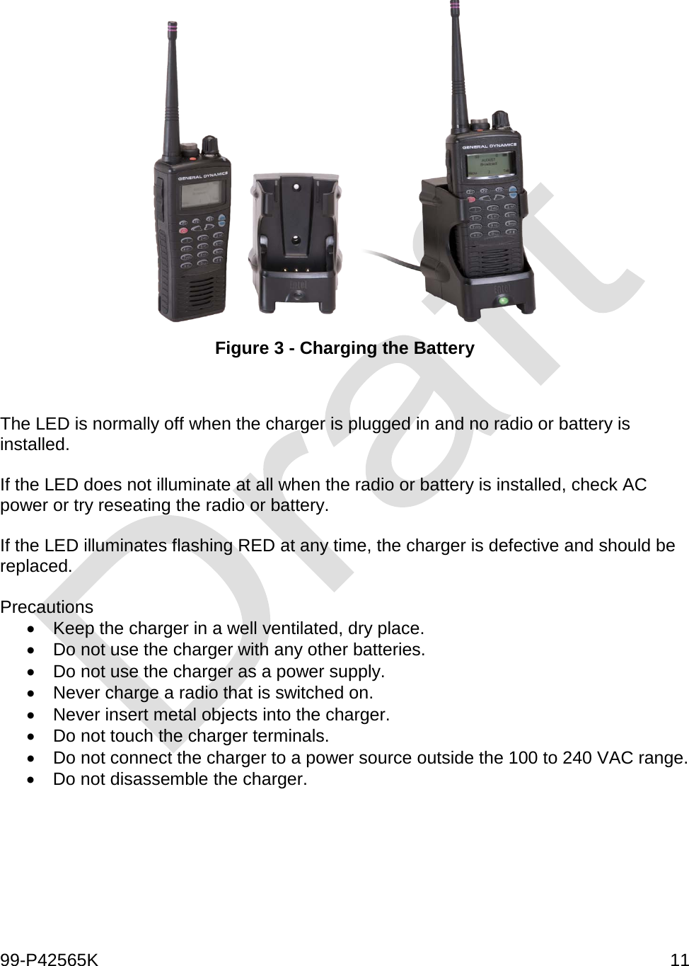
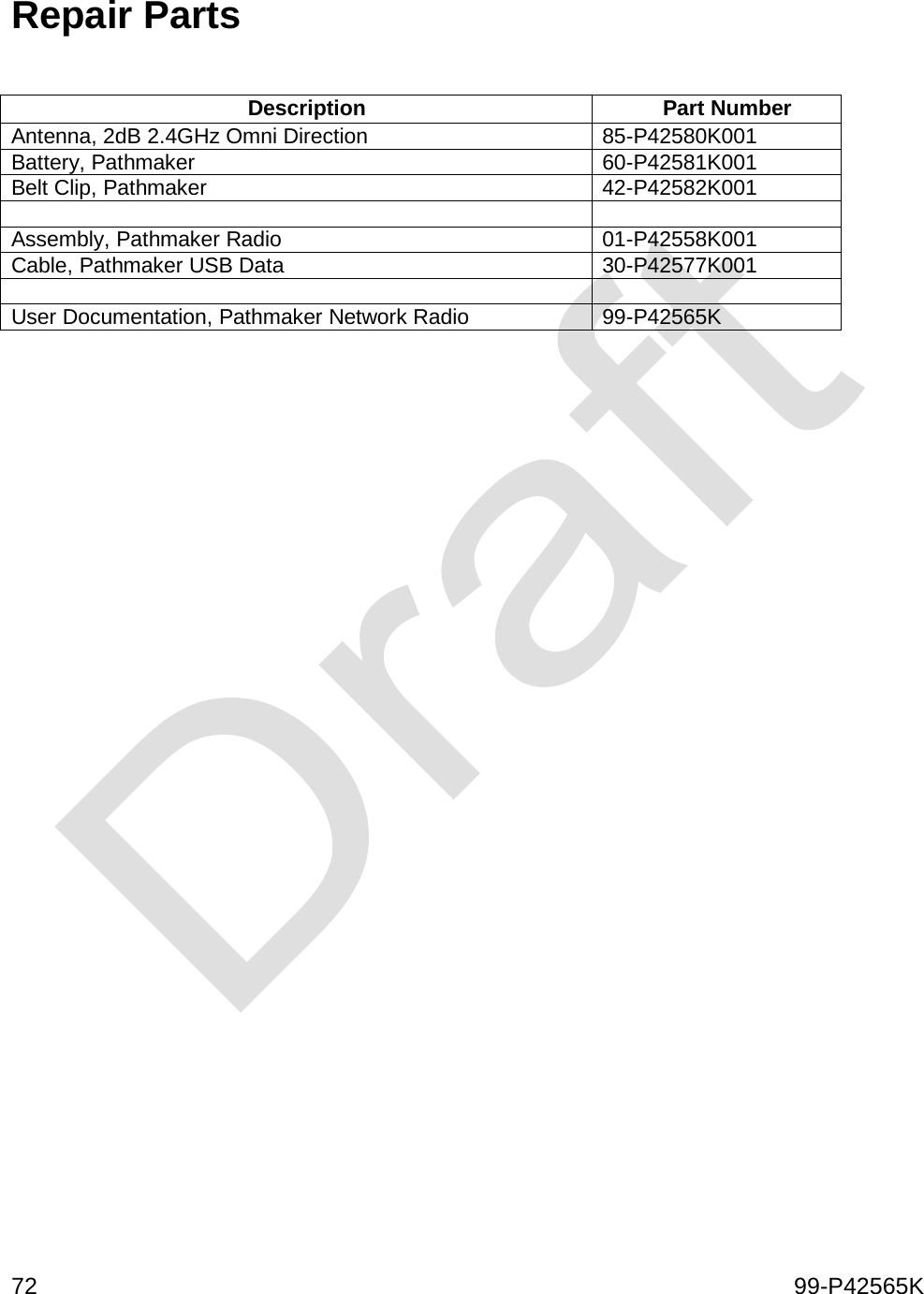
![10 99-P42565K SETUP Normal setup includes unpacking, inspecting for damage, and charging the battery. Other setup procedures specific to a particular operating mode are included in the Operation section of this manual. Unpacking Inspect the hardware for damage. Retain the packing material and the shipping container, if desired, for possible future use. Return shipping label? Instructions? Charging the Battery The battery charger provides rapid recharging of the lithium-ion battery pack provided with the Pathmaker radio. The charger may be placed on any flat surface, such as a desktop, or it may be bulkhead mounted using the [provided?] mounting hardware. The battery may be inserted into the charger alone or while mounted to the radio. When charge is complete, the charger automatically switches to standby mode. Two chargers are available, a single-unit charger as shown below, and a six-unit charger. The operation for each is the same. The normal time to charge a fully discharged battery is 120 minutes. To operate the charger: 1. Plug the AC power cord of the charger into an AC supply between 100 to 240 VAC. The LED should not illuminate. If it does illuminate, check the AC supply or replace the charger. 2. Switch the radio off. 3. Insert the battery into the charger, either with or without the radio attached. The LED will illuminate RED indicating the battery is charging. 4. When the LED illuminates GREEN, charge is complete. The radio may be removed or may remain in place on the charger.](https://usermanual.wiki/General-Dynamics-Mission-Systems/PNR-1000/User-Guide-1658116-Page-21.png)
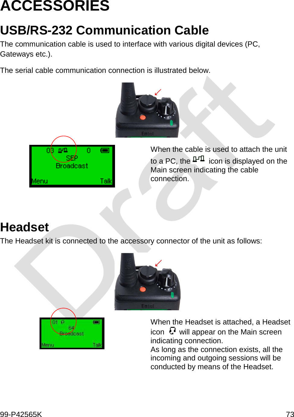
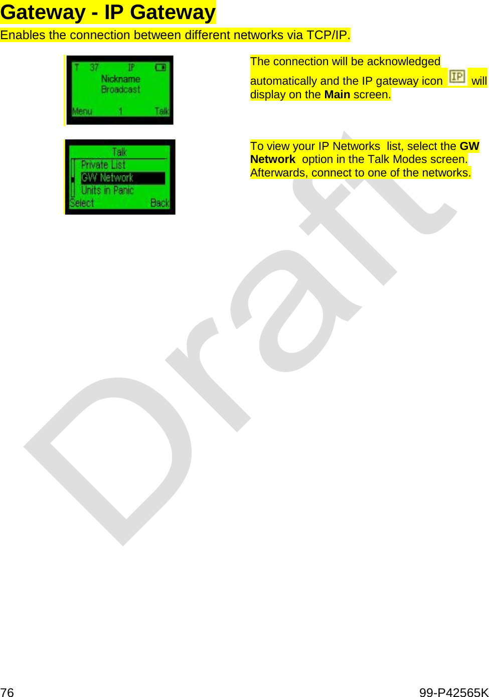
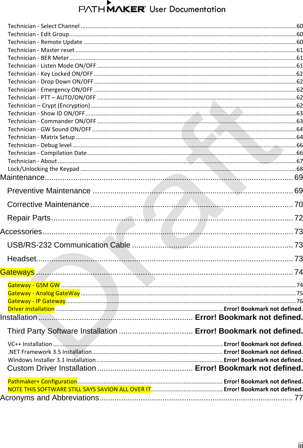
![99-P42565K 75 When in a call, use the PPT key just as you would when using the radio in the voice mode. That is, push to talk and release to listen. Callers from conventional telephones must dial the GSM Gateway’s telephone number. Upon connection, callers will be prompted to also enter the target radio’s Unit ID number. Gateway - Analog GateWay In this mode you can use the gateway to communicate with other devices. Radios connect to the Analog Gateway over-the-air. The Multi-GW unit defines which units in the Pathmaker network will receive the analog network session and defines which Pathmaker network sessions will be transmitted to the analog network. • When the [A] icon is present on the general screen of the unit, in “Talk” mode of the unit will appear additional talk mode “Analog GW”. • Use regular broadcast call in order to perform a voice call to the analog network. • Management of the Multi GW unit can be done from the Pathmaker Suite application remotely. • Only one session to/from analog network can be done at a time.](https://usermanual.wiki/General-Dynamics-Mission-Systems/PNR-1000/User-Guide-1658116-Page-86.png)