General Research of Electronics 0715 Scanning Receiver User Manual ADV0715 Manual
General Research of Electronics Inc Scanning Receiver ADV0715 Manual
Users Manual
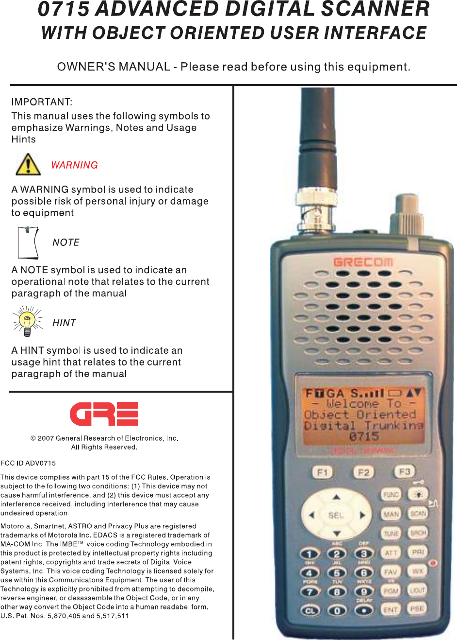
Table of Contents
..........................................................................................................Introduction!5
...........................................................................................................Features!6
..........................................Overview of the Object Oriented User Interface!8
...............................................................................................Background!8
......................................................What is Object Oriented Scanning?!11
........................................................................................About this manual!13
.......................................Object abbreviations used in this document!13
..................................................................................................TGRP!13
...................................................................................................TSYS!13
..................................................................................................CONV!14
....................................................................................................LMIT!14
..................................................................................................SRVC!14
..................................................................................................SWPR!14
......................................................................The FCC Wants You To Know!14
..........................................................................................Scanning Legally!15
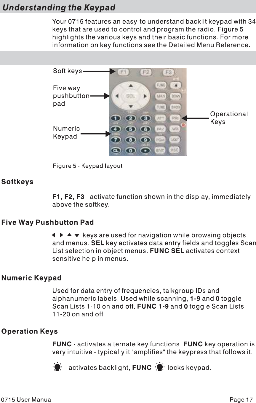
.......................................................................Getting Familiar With Your 0715!17
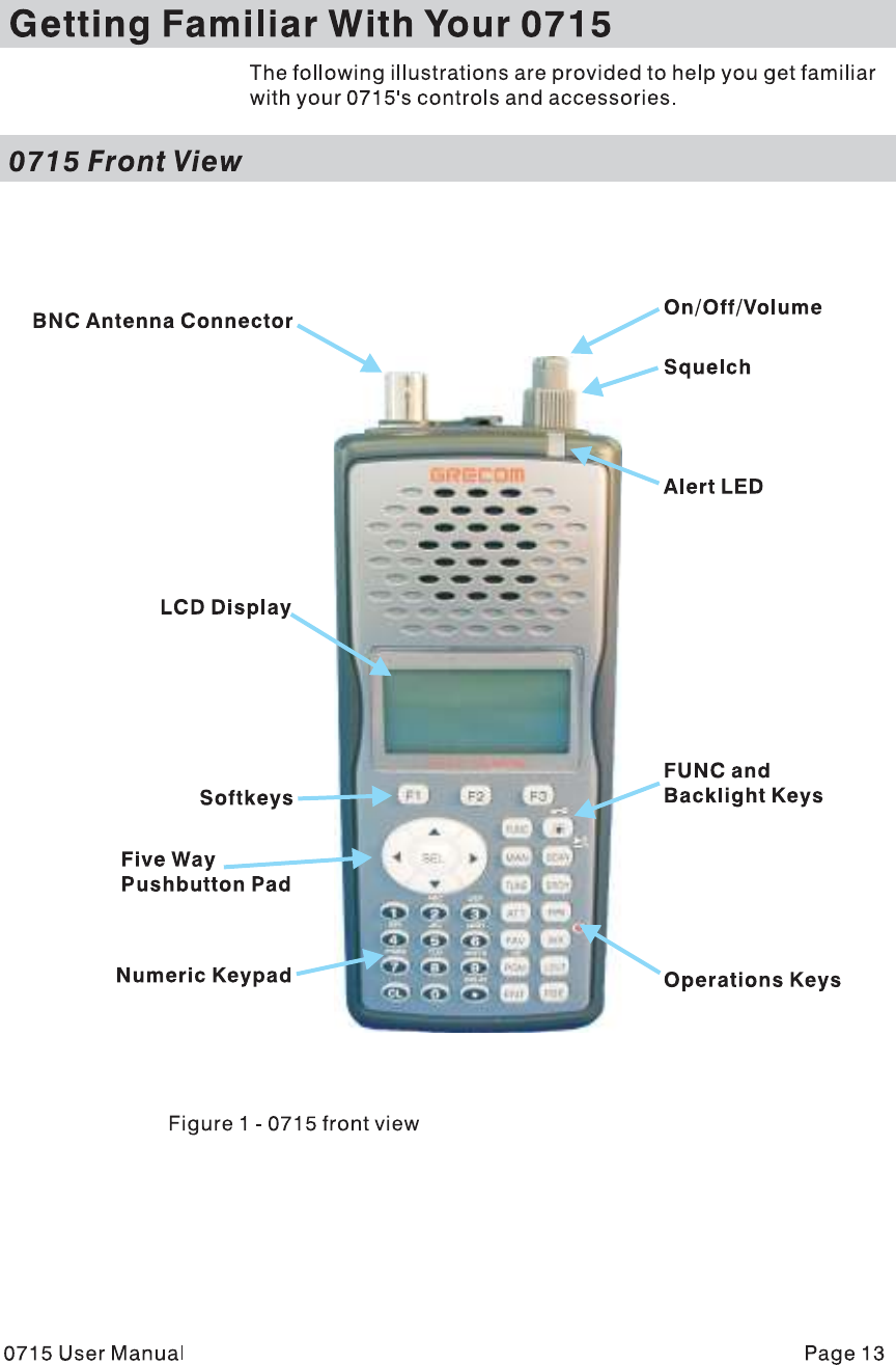
............................................................................................0715 Front View!17
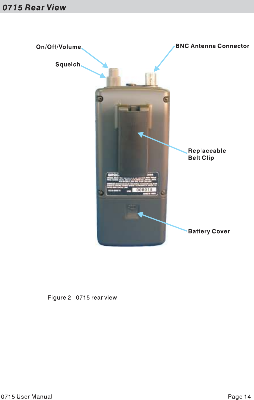
.............................................................................................0715 Rear View!18
.........................................................................................0715 Accessories!19
...............................................................Understanding the Display Icons!20
..........................................................................Understanding the Keypad!21
...................................................................................................Softkeys!21
......................................................................Five Way Pushbutton Pad!21
......................................................................................Numeric Keypad!21
.......................................................................................Operation Keys!21
...................................................................................................Getting Started!23
.........................................................................................First Time Startup!23
.....................................................................................Unpack the radio!23
..................................................................................Insert the batteries!23
..................................................................................Attach the antenna!24
.....................................................................................Turn the radio on!24
.................................................................Creating Your First New Objects!24
..................................................Conventional Channel Object (CONV)!25
.................................Essential Conventional Channel parameters!25
.......................................................................Talkgroup Object (TGRP)!28
......................................Essential Trunking Talkgroup parameters!28
...............Setting up and using a Trunking System (TSYS) object!28
..................................................Using DUPE to speed up object entry!32
.....................................................................Basic Scanning Operation!32
............................................................................Advanced Startup Topics!35
.......................................................................About Object Numbering!35
...............................................................................Search Object Types!35
...............................................................Limit Search Object (LMIT)!36
............................................Essential Limit Search parameters!36
..................................................Spectrum Sweeper Object (SWPR)!37
..................................Essential Spectrum Sweeper parameters!38
.........................................................Service Search Object (SRVC)!39
........................................Essential Service Search parameters!39
............................................................Grouping Objects in Scan Lists!41
...................................................................................Geographically!42
...........................................................................By trunking system!42
....................................................................................By object type!42
....................................................................................By application!43
........................................................Mapping Objects to Scan Lists!43
..................................................Enabling and disabling Scan Lists!44
..............................................................................Other Startup Topics!45
..........................................................Finding Stored Objects Easily!45
............................................Searching For Objects Using FIND!45
..............................................................Filtering By Object Type!45
..................................................................................Object Lockout!46
......................................................................Temporary Lockout!46
.....................................................................Permanent Lockout!47
............................................................................Search Lockout!47
.......................................................................Talkgroup Lockout!48
................................................................................Deleting Objects!49
......................................................................................Priority Scan!49
...............................................Turning Object Priority On or Off!49
........................................Turning Priority Scan Mode On or Off!50
......................................................................CONV Priority Scan!50
......................................................................TGRP Priority Scan!50
...............................................Audible Alarms and the ALERT LED!51
...................................Audible Alarm and ALERT LED Settings!51
................................ALERT LED with Audible Alarm Examples!51
..................................................................Dedicated search modes!52
.................Using Dedicated Spectrum Sweeper (SWPR) Mode!52
......................................................Using dedicated TUNE mode!54
...................Using dedicated Limit and Service search modes!55
.......................................................................LMIT Search Mode!55
......................................................Using dedicated SRVC mode!56
.......................................................................Using Weather Modes!58
....................................................................Weather Radio Mode!58
.................................................................Weather Priority Mode!59
...................................................................SAME Standby Mode!59
.................................................................SAME Entry Examples!61
...............................Entering SAME Location and Event Codes!62
.................................................Activating SAME Standby Mode!65
.................................................................Using V-Scanner Storage!65
.............................Saving Main Memory To A V-Scanner Folder!66
..............Loading A Stored V-Scanner Folder To Main Memory!66
.........................................................Erasing V-Scanner Folders!67
..............................................Standard Text Entry Method and QuickText!67
.................................Entering and Editing Alphanumeric Information!67
......................................................................................Using QuickText!69
..........................................................................Customizing QuickText!70
..................................................................................Detailed Menu Reference!70
................................................................................GLOB Menu Reference!72
................................................................................CONV Menu Reference!75
.................................................................................TGRP Menu Reference!77
.................................................................................TSYS Menu Reference!79
..................................................................................LMIT Menu Reference!81
.................................................................................SRVC Menu Reference!83
................................................................................SWPR Menu Reference!86
...................................................................................................................Index!89
.....................................Appendix A - Remote Control Protocol Version 0.01!92
................................................................................................Get Status!92
....................................................................................................Get LCD!93
..................................................................................................Send Key!93
...............................Appendix B - Frequency, Step and Mode Specifications!95
........................................Appendix C - General Specifications (Preliminary)!96

Introduction
Welcome to an exciting new world of radio scanning!
Recognizing that contemporary scanning receivers are too hard
to program and use, GRE!s engineers conducted extensive
research to determine the functional requirements for an entirely
new scanning receiver user interface. We call this new user
interface the Object Oriented User Interface (OOUI), and it is
based on the premise that, to a hobbyist, a scanner is easiest to
use if all of the things that can be scanned are handled using
common conventions for interaction between the user and the
radio, at least to the extent that this is possible given that the
“things” that can be scanned are different from one another in
either subtle or major ways.
In this new user interface design, we call “things” that can be
scanned Scannable Objects. Simply put, a Scannable Object is
defined as something that can be scanned or monitored.
Scannable Objects include the following:
•Conventional, non-trunked radio channels
•Trunked talkgroups used on a trunked radio system
•Service searches to search for a specific radio service
•Search ranges with upper and lower limits
•Spectrum Sweeper setups with band segments that can be
enabled or disabled by the user
One of the goals of the Object Oriented User Interface is to make
the scanner as easy to use as possible. The OOUI does this by
treating all Scannable Objects the same in terms of how they are
created, edited, manipulated and grouped. Once you have
learned how to create and store a conventional channel, you
know most of what you need to know to create a trunking
talkgroup, and so on.
While we have designed this radio to be the easiest scanning
receiver in its class to program and use, we encourage you to
read this manual in its entirety so that you will fully understand all
of the radio!s capabilities. However, if you consider yourself to be
an experienced scanning hobbyist and are feeling adventurous,
we invite you to dive right in and get started programming your
favorite “objects” into the radio.
0715 User Manual"Page 1

Features
Upgradeable CPU and DSP Firmware - keep your radio current
with enhancements as they become available with free upgrades
from www.greamerica.com!
Intuitive "Object Oriented" User Interface Design is designed
for ease of use, yet powerful enough to satisfy the most
sophisticated experts. Common data entry, browsing and control
methods are used for non-trunked conventional channels,
trunking talkgroups, search configurations and Spectrum
Sweeper setups. The radio grows with you – you can start out
with a small, easy to manage configuration, then expand it
whenever you need to.
Menu Driven Programming With Context Sensitive Help -
Each menu item provides a few lines of help text that provide
assistance with programming and using the scanner.
Powerful and flexible Scan List functionality allows you to
arrange, group and scan objects according to your preference.
Flexible Free-Form Memory Organization - memory is
assigned as objects are created using a sophisticated internal file
management system. You are not constrained to traditional bank/
channel scanner memory layouts. No memory is wasted as a
result of bank/channel programming constraints. The scanner
has sufficient main memory capacity to store over 1,800
conventional channels, trunking talkgroups, search
configurations and Spectrum Sweeper objects in any
combination, providing ample capacity for more sophisticated
hobbyists and professionals while keeping the database size
manageable for beginners.
GRE's Exclusive V-Scanner Technology - Allows you to save
complete radio configurations within the radio, for recall into main
memory as needed in the field. This is similar to having a laptop
computer and programming software available anytime. You can
use V-Scanners to store configurations for different geographical
areas or usage styles. Twenty one V-Scanner Folders are
provided, each capable of storing over 1,800 objects. Total
memory capacity of main memory combined with V-Scanners is
over 37,800 objects!
SKYWARN Storm Spotter Functionality - Instant, one button
access to frequencies used by storm spotter networks. You can
monitor storm conditions as they occur, and become aware of
0715 User Manual"Page 2
dangerous conditions before the media or emergency
management officials are able to announce them to the general
public.
SAME and All Hazards Weather Alerting - Your scanner can
operate in dedicated SAME weather alerting mode, and alert you
to severe weather and other hazards in the specific area(s) that
you select, or, your scanner can check your local NOAA weather
frequency periodically, even while scanning and alert you when
an All Hazards alert occurs.
Multi-System Trunking - Scans most common trunked radio
system signaling formats, including Motorola, EDACS, LTR and
P25 trunked radio networks. Talkgroup and individual call
monitoring is supported.
GRE's Exclusive Automatic Adaptive Digital Tracking - When
monitoring P25 digital systems, instantly adapts the digital
decoder to the digital modulation format of the transmitted signal,
then analyzes the signal over 50 times each second and adapts
to any subtle changes caused by multipath or fading. No
cumbersome manual adjustments are required.
GRE's Exclusive Digital AGC - instantly compensates for low
user audio levels that are very common on digital systems. The
radio is easier to listen to, and provides you with a more
enjoyable scanning experience.
The Best Subaudible Squelch Decoder in the Scanning
Industry - CTCSS and DCS subaudible squelch coding is
processed by the same powerful DSP chip that is used for P25
digital decoding. Provides fast and reliable decoding of
subaudible squelch signaling with squelch tail elimination.
Powerful Spectrum Sweeper - Quickly sweeps the scanner!s
frequency ranges for transmissions from nearby transmitters.
P25 NAC Functionality - Much like CTCSS and DCS with
analog signals, P25 Network Access Code (NAC) is used to
provide selective squelch operation on conventional digital
channels. Your 0715 will detect the NAC that is being used on a
P25 conventional digital channel, and allow you to program NAC
codes to block transmissions that do not have a matching NAC,
including analog traffic on the same frequency!
Exclusive ALERT LED - Programmable tri-color LED can be
configured to illuminate or flash when certain objects are active.
0715 User Manual"Page 3

Eight user-defined colors and brightness levels can be specified
from thousands of possible combinations. Provides visual alerts
when certain channels are active, e.g., blue can be used to
signal activity on your primary police channel, red for fire, etc.
Audible alarms - Programmable audible alarms can be
configured to sound when certain objects are active. Can be
used in conjunction with, or separately from, the ALERT LED
described above.
High Speed PC Interface - uses GRE!s 30-3290 USB cable in
full duplex mode at 6 times the speed of previous scanner
models for PC transfer and 8 times the speed of previous models
for radio to radio cloning.
Real-time Signal Strength Indicator – shows relative strength
of received signals.
Sleek, compact case design with large speaker is designed
for one-handed operation and ease of use.
Overview of the Object Oriented User Interface
Background
Scanner hobbyists who have been involved in the hobby long
enough probably remember the days before microprocessor
technology reached the point where it feasible for use in
everyday consumer devices. Back then, scanners were relatively
limited in what they were able to do. A typical scanner was able
to scan between 2 and 10 frequencies. The frequencies were
selected using plug-in crystal elements, and a custom crystal had
to be purchased for each frequency that a user wished to scan.
Scanning activity was typically shown using a row of
incandescent or LED indicators. These indicators would show
scanning operation in progress as the scanner moved from one
channel to the next, looking for activity, and would indicate the
active channel when activity was found. Pushbuttons or switches
were used to skip or lock out undesired channels. The scanning
row of LED or incandescent indicators seemed to personify the
hobby at the time, and it was quite an experience to see the light
show from multiple radios in a well-equipped scanner shack
Early microprocessor controlled scanners eliminated the need for
crystals and increased the number of channels that could be
scanned. Without keypads and numeric or alphanumeric displays
these early microprocessor controlled radios still relied on the
0715 User Manual"Page 4
traditional row of lights to show scanning activity. A row of
switches was used to enter binary code to store individual
frequencies. In some later models a punch card or metal comb
was used to load the binary code.
The true predecessors of today!s modern scanning receivers are
those first radios to use a numeric keypad to store frequency
information and control the radio, and numeric LCDs to show the
programmed information and display the status of the radio. The
row of lights was replaced with a row of zeroes or other display
elements in the LCD to show scanning activity.
As it became possible to increase the memory capacity of these
microprocessor controlled scanners, designers started looking
for ways to organize this expanded memory to make operation
easier for users. This lead to the typical bank/channel memory
organization that is still used in many scanning receivers today.
This design works well when scanning conventional, non-trunked
frequencies.
Trunking presented new challenges for designers. Early designs
operated in trunking or conventional mode, but not both at the
same time. Because programming for trunked systems includes
many parameters not normally used in conventional radio
scanning, it was necessary to design a completely separate user
interface for entering trunking parameters and scanning trunked
systems. Soon after the first early models were released, new
“multi-scanning” receivers appeared that allowed users to scan
different combinations of trunked systems or conventional
channels simultaneously.
Trunking scanners soon earned a reputation for being complex
and difficult to program. Even experienced expert users were
frustrated when confronted with the challenges of programming
and operating a trunked scanning receiver. Part of the problem
with trunking scanners was the way that trunking functionality
was added to the radio. Until recently, trunking functionality was
forced into the traditional bank/channel scanner design. This
created confusion and frustration for users, who had to learn two
different methods for programming and controlling their scanners
– one for conventional, non-trunked channels, and another for
trunked systems and talkgroups.
GRE!s engineers have studied the challenges of programming
and operating today!s current crop of trunked scanning receivers.
We have also carefully studied how scanning hobbyists like to
use their radios, and the role the Internet plays in the scanning
0715 User Manual"Page 5

hobby. We have studied the scanning hobby itself, which has
changed dramatically over the years as radio systems, scanning
receivers and scanner hobbyists have all become more
sophisticated. Sophistication is a generally good thing, but in this
case it can have the effect of locking out newcomers to the
hobby.
Our engineers decided that an entirely new method of
programming and controlling scanning receivers was needed –
essentially, a new user interface. Several design objectives were
defined. These included the following:
•There should be a strong focus on ease-of-use. The radio
should do as much work as possible for the user. A brand
new hobbyist should be able to begin using the radio quickly
with minimal frustration. There should also be enough
advanced features and functionalities to satisfy the most
sophisticated expert users.
•The user interface should be intuitive. Interactions with the
radio should be standardized to the extent possible. For
example, the same basic methods should be used whether
adding a new conventional channel or adding a trunked
talkgroup.
•The scanner should include efficient memory usage. Bank/
channel designs result in much wasted memory. Memory
should be allocated as it is needed for new objects.
Our engineers realize that our scanners are used by a wide
variety of users with varying levels of experience and expertise.
These include amateur radio operators, scanner hobbyists, fire
buffs, railfans, public safety professionals, volunteer firefighters,
news and media organizations, and most importantly, everyday
people who just want to know what is going on around them.
All of these users have a few things in common about the way
they use scanning receivers. First, they all follow the same basic
process when configuring and programming the radio for use.
Second, all have one or more collections of frequencies,
talkgroups, or other things they listen to.
As our engineers studied the scanning hobby and those who use
scanners, they began to realize that the scanning hobby had
much in common with hobbies that involve collections, like stamp
collecting, coin collecting, and so on.
0715 User Manual"Page 6
Hobbies of collection all have some things in common:
•Typically, a collector starts off small, and adds to the
collection
•A collector groups items in the collection according to their
type
•A collector looks for new things to add to the collection
•A collector removes items from the collection that they no
longer desire
•A collector enjoys the collection
Specifically, with regard to scanning:
•At first, the typical scannist starts off small, and expands. This
is especially true with beginners and newcomers to the
hobby.
•The scannist groups channels and talkgroups according to
area or type of use
•The scannist searches or tunes to find new things to scan
•A scannist removes channels and talkgroups they no longer
need
•A scannist enjoys the collection of channels and talkgroups
they have programmed into the scanner
Our engineers determined that a new scanner design would be
most useful if it could be used as a tool by the scanning hobbyist
to build and enjoy the collection of channels and trunked
talkgroups they have programmed into the scanner.
Much of what you see in the design of your new GRE scanner
with Object Oriented User Interface is intended to meet the
objectives we describe above, and serve as a tool to help you
manage and enjoy your collection of “Scannable Objects”.
What is Object Oriented Scanning?
To put it simply, Object Oriented Scanning describes a new user
interface design for scanning receivers (the Object Oriented User
Interface, or OOUI). In Object Oriented Scanning, we introduce
0715 User Manual"Page 7
the concept of the Scannable Object. A Scannable Object is
defined as “something that can be scanned”.
The Scannable Object concept is very important in the OOUI
design. Recall that one of the more frustrating things about
current trunking scanners is that entirely different methods of
programming and interacting with the radio are used depending
on whether the user is working with trunking talkgroups or
conventional channels. A method that works with one does not
work with the other. The user must learn two entirely different
“languages” for “talking to” the radio – one for trunking and one
for conventional, non-trunked frequencies.
What if it was possible to use the same basic “language”
regardless of whether a user is working with trunked talkgroups
or conventional channels, such that once a user has learned how
to enter a conventional channel into memory, they already know
most of what they need to know to enter a trunked talkgroup? Or,
a search range, or other “Scannable Objects”? This is how the
OOUI works – the two primary Scannable Objects, talkgroups on
trunked radio systems and conventional non-trunked frequencies
use the same user interface elements.
Additionally, we include limit and service search configurations
and Spectrum Sweeper configurations as Scannable Objects.
This means that it is possible to create, edit, group, scan and
delete service and limit searches, and SWPR configurations
using the same methods that are used when working with
trunked talkgroups and conventional channels.
Object Oriented Scanning also lends itself quite well to the
“collector hobbyist model” we describe above. Object Oriented
Scanning makes it very easy for newcomers to the hobby or the
radio to start off with a small collection Scannable Objects and
expand their collection as needed later. Object Oriented
Scanning makes it easy to group Scannable Objects in Scan
Lists, a powerful and flexible grouping system. Object Oriented
Scanning makes it easy to search for new frequencies or
talkgroups to monitor, and add them to existing or new Scan List
groups. Object Oriented Scanning makes it very easy to delete
or deactivate objects and Scan Lists that you do not want to
listen to, including a powerful temporary lockout mode that allows
you to zero in on activity associated with a specific incident, then
restore your desired configuration when the incident is over.
Finally, Object Oriented Scanning makes it exceedingly easy for
0715 User Manual"Page 8

the scannist to enjoy the collection of channels and talkgroups
they have programmed into the scanner.
About this manual
Object abbreviations used in this document
We described how your new GRE scanner utilizes an Object
Oriented User Interface in the Introduction and Overview
sections of this manual. You learned that the key components of
this new user interface are the Scannable Objects, which are, of
course, “things that can be scanned”. As you begin to use your
new scanner, you will notice that the object names are
abbreviated so that they can easily fit into the 16 character LCD.
(Imagine what the radio!s display would look like if “Trunking
Talkgroup Object” was spelled out in its entirety every time it was
necessary to show it in the display.)
You should take a moment and become familiar with these
abbreviations now. For consistency, the same abbreviations for
the different object types are used in the radio and here in the
manual.
TGRP
TGRP is used to represent a Trunking Talkgroup Object.
Trunking Talkgroups are “virtual” channels that exist on a trunked
radio system. A trunked radio system is a radio system where a
small group of radio channels are automatically shared between
a larger number of users and user groups. This of sharing of
channels is managed automatically by a special computer, called
a controller, or by other specialized hardware. For now, all you
need to know is this; if you want to monitor a talkgroup on a
trunked radio system, you must store that talkgroup!s parameters
in a TGRP object.
TSYS
TSYS is used to represent a Trunking System Object. A TSYS is
a special object type that is used when creating TGRP objects. A
trunking talkgroup must be associated with a specific trunked
radio system in order for it to operate. There are parameters that
are associated with trunking systems, such as the type of
trunked radio system technology is used, the frequencies that the
system uses to broadcast control data, etc. Instead of entering
these parameters over and over again every time you create a
new TGRP on the same trunked radio system, you create a
0715 User Manual"Page 9

TSYS object with all of the system parameters, then specify that
TSYS object for each TGRP you create on the same trunked
radio system. A TSYS cannot be scanned by itself and is not
considered a Scannable Object. It is a “configuration object” that
can be used over and over again when adding talkgroups for a
specified trunked radio system.
CONV
CONV is used to represent a Conventional Channel Object. A
Conventional Channel Object is a regular, non-trunked frequency
used for radio communications. CONV objects are used to store
the parameters for any radio channel that is not a part of a
trunked system. For example, if you want to monitor specific VHF
marine channels, they should be programmed as CONV objects.
If you want to monitor your favorite amateur radio repeater, it
should be stored as a CONV object. If your police or fire
department uses a channel, or channels that are not trunked, but
part of a “plain old radio system”, they should be stored as
CONV objects.
LMIT
LMIT is used to represent a Search Range, or Limit Search
Object. LMIT objects contain the parameters necessary for the
radio to search a range of individual frequencies between a lower
and upper limit frequency.
SRVC
SRVC is used to represent a Service Search Object. SRVC
objects are further divided into Public Safety, Aircraft, Amateur,
CB, Marine, and FRS/GM/MURS/DOT. SRVC objects are similar
to LMIT objects, but are preprogrammed to search all
frequencies associated with the selected service. For example,
selecting the Amateur SRVC search will search selected amateur
radio frequency ranges frequencies in the VHF and UHF portions
of the radio spectrum.
SWPR
SWPR is used to represent a Spectrum Sweeper Object. SWPR
objects contain the parameters necessary for the radio to rapidly
sweep a range of radio spectrum for strong signals from nearby
transmitters.
The FCC Wants You To Know
This equipment has been tested and found to comply with the
limits for a scanning receiver, pursuant to Part 15 of the FCC
0715 User Manual"Page 10

Rules. These limits are designed to provide reasonable
protection against harmful interference in a residential
installation. This equipment generates, uses and can radiate
radio frequency energy and, if not installed and used in
accordance with the instructions, may cause harmful interference
to radio communications.
However, there is no guarantee that interference will not occur in
a particular installation. If this equipment does cause harmful
interference to radio or television reception, which can be
determined by turning the equipment off and on, the user is
encouraged to try to correct the interference by one or more of
the following measures:
• Reorient or relocate the receiving antenna.
• Increase the separation between the equipment and receiver.
• Connect the equipment into an outlet on a circuit different from
that to which the receiver is connected.
This device complies with Part 15 of the FCC Rules. Operation is
subject to the following two conditions:
1."This device may not cause harmful interference.
2."This device must accept any interference received, including
interference that may cause undesired operation.
Scanning Legally
Your scanner covers frequencies used by many different groups
including police and fire departments, ambulance services,
government agencies, private companies, amateur radio
services, military operations, pager services, and wireline
(telephone and telegraph) service providers. It is legal to listen to
almost every transmission your scanner can receive. However,
there are some transmissions you should never intentionally
listen to. These include:
•Telephone conversations (cellular, cordless, or other means
of private telephone signal transmission)
•Paging transmissions
•Any intentionally decoded scrambled or encrypted
transmissions
0715 User Manual"Page 11
According to the Electronic Communications Privacy Act (ECPA),
you are subject to fines and possible imprisonment for
intentionally listening to, using, or divulging the contents of such
a transmission unless you have the consent of a party to the
communication (unless such activity is otherwise illegal).
This scanner has been designed to prevent reception of illegal
transmissions. This is done to comply with the legal requirement
that scanners be manufactured so as to not be easily modifiable
to pick up those transmissions. Do not open your scanner's case
to make any modifications that could allow it to pick up
transmissions that are illegal to monitor. Doing so could subject
you to legal penalties.
We encourage responsible, legal scanner use.
In some areas, mobile use of this scanner is unlawful or requires
a permit. Check the laws in your area. It is also illegal in many
areas to interfere with the duties of public safety officials by
traveling to the scene of an incident without authorization.
0715 User Manual"Page 12
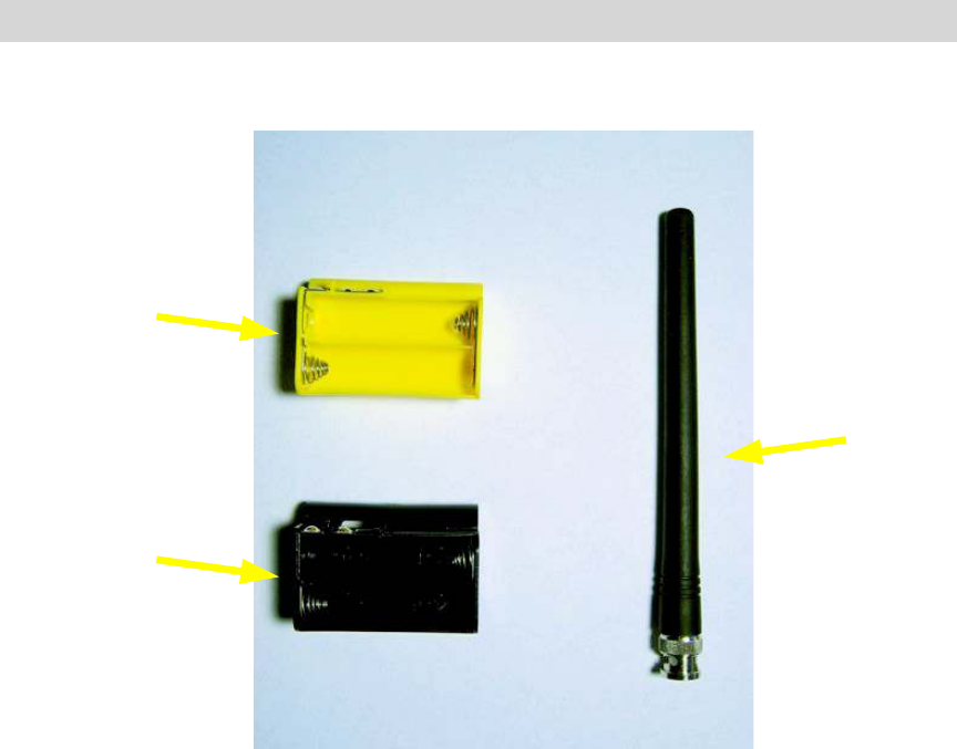
0715 Accessories
Figure 3 - 0715 Accessories
0715 User Manual"Page 15
Yellow battery
holder for
rechargeable
batteries
Antenna
Black battery
holder for
standard batteries
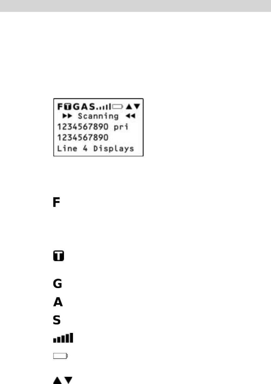
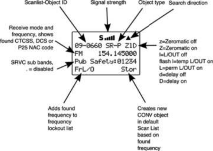
Understanding the Display Icons
Your 0715 features a high contrast, backlit Liquid Crystal Display
(LCD) to provide important information about the status of the
radio while you are programming and using it. The LCD includes
a row of icons at the top that provides information about the
status of the scanner while it is operating. Beneath this row of
icons, there are 4 rows of 16 characters each that provide
alphanumeric information for frequencies, object names, Scan
List status and menu information. Figure 4 provides an example
of the display that is shown while the radio is scanning.
Figure 4 - Scanning Display
The top row of icons are defined as follows:
The Function Key (FUNC) has been pressed. FUNC acts
as a “shift” key and typically enhances in some way the
action of the button that follows it. When using FUNC,
press the FUNC key first and release it, then press the
next key.
The scanner is currently receiving trunking control channel
data.
The attenuator is set for Global mode.
The attenuator is currently active.
The radio!s squelch circuit is open.
Signal meter indicating strength of the received signal.
Battery status indicator. Comes on solid when battery is
weak, and flashes when battery failure is imminent.
Menu position and search direction indicators.
0715 User Manual Page 16
MAN - Places scanner in Manual Mode for monitoring single
objects.
SCAN - Places scanner in Scan Mode for scanning enabled
objects, FUNC SCAN launches Spectrum Sweeper.
TUNE - Allows direct tuning of any valid frequency, FUNC TUNE
loads the current or most recently scanned frequency into TUNE
SRCH - Dedicated Search mode for service and frequency
searches
ATT - Toggles Attenuator on and off, FUNC ATT toggles Global
Attenuator mode
PRI - Toggles the Priority setting for selected or active object,
FUNC PRI toggles Priority Mode on or off for the scanner
FAV - Activates Favorites Scan Mode, FUNC FAV adds the
current object to the Favorites scan list
WX - Activates Weather scan, FUNC WX activates Skywarn mode
PGM - Places scanner in Program Mode for editing radio-wide
options, adding new objects or editing existing objects, FUNC
PGM accesses V-Scanner mode
L/OUT - Toggles Temporary Lockout on active or selected object,
FUNC L/OUT applies permanent lockout (can be changed in the
GLOB menu)
ENT - Enter key
PSE - Pauses scan or search operation on active object
0715 User Manual"Page 18

Getting Started
First Time Startup
We believe that your new 0715 is so easy to use that scannists
with at least some experience in the hobby should be able to get
up and running in a matter of just a few minutes. If you already
know the difference between a conventional channel and a
talkgroup, or a search range and a Spectrum Sweeper, we invite
you to dive right in and set the radio up to begin scanning your
first objects. If you get stuck, you can refer to this Getting Started
section, or see the relevant sections in the Detailed Menu
Reference. Otherwise, please read on and allow us to help you
get acquainted to your new scanner!
Unpack the radio
Unpack your radio carefully. Save all documentation and packing
materials in case it is necessary to return your scanner for repair.
Insert the batteries
Remove the door covering the battery compartment by pressing
gently where the door is marked OPEN and sliding the door
downwards until it stops, approximately 1/4”. Lift the door away
from the radio. Remove the supplied battery holder. Insert four
AA batteries into the holder, taking care to ensure that the
batteries are inserted according to the diagram shown inside of
the holder assembly. Insert the holder into the battery
compartment, then replace the battery compartment door by
placing it back over the batteries and sliding it upward gently until
it locks in place.
NOTE: Two battery holders are included with your 0715. The black battery
holder should be used with non-rechargeable alkaline batteries. The
yellow battery holder should be used with rechargeable NiMH or
NiCAD batteries. The radio will charge the batteries when the yellow
holder is used in conjunction with an approved AC adapter.
WARNING: Never place non-rechargeable batteries in the yellow holder.
Intentionally or accidentally recharging non-rechargeable
batteries will cause them to leak or explode.
0715 User Manual"Page 19
Attach the antenna
Remove the antenna from its protective plastic wrapper. Align the
slots on the antenna!s BNC male connector with the posts on the
radio!s BNC female connector and slide the antenna in place,
then rotate the antenna!s BNC connector 1/4 turn clockwise until
it snaps in place.
Turn the radio on
Rotate the top knob of the VOLUME/SQUELCH control
clockwise to turn the radio on. Set both the VOLUME and
SQUELCH knobs at their mid-point (12 o!clock) position.
NOTE: While 12 o!clock is a good squelch setting to start with, it may cause
your radio to miss some calls with weak signals. You will probably
want to optimize the squelch setting to set it close to threshold. To
optimize the squelch setting to be close to the best threshold, press
TUNE, then rotate the squelch control counterclockwise until a
rushing sound is heard from the speaker. Rotate the squelch control
clockwise just past the point where the rushing sound stops. The
squelch is now set to the optimum point. Please note the position of
the squelch control for future reference. Once the squelch setting is
complete, you may press PGM to exit TUNE mode.
Creating Your First New Objects
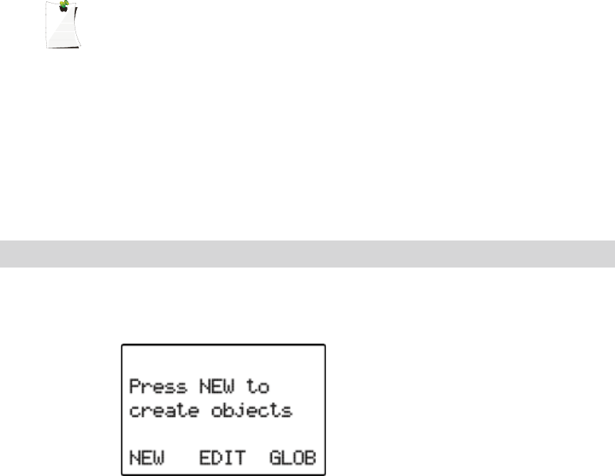
When the scanner is first turned on after it is unpacked, you are
working with a clean slate. You will notice that your scanner tells
you this:
The scanner is in program mode and is ready for you to enter the
first Objects into the memory. The scanner prompts you to
Press NEW to create objects.
You will also notice that there are three pushbutton keys beneath
the display, and above each button in the display, a label that
indicates the current function of these three keys. These keys
are called softkeys, and they function much like the softkeys on
0715 User Manual Page 20
many Automatic Teller Machines. Their meaning can change
depending on the operational state that the radio is in. Right now,
the softkeys on your radio should read as follows:
NEW EDIT GLOB
Let!s focus on the NEW softkey for a few minutes. As you might
have guessed, NEW is an invitation for you to create a new
Scannable Object (CONV, TGRP, LMIT, SRVC, or SWPR). So,
what would you like to create first? We suggest that you start
with a Conventional Channel Object (CONV) first, to get familiar
with the radio!s user interface and display.
Conventional Channel Object (CONV)
A Conventional Channel Object (CONV) is a record that stores
the parameters for a regular, non-trunked conventional AM or FM
channel. When you create a CONV object, you are creating an
object that will allow you to scan and monitor a “plain old radio
channel”, that is, a single frequency and the associated
parameters that are necessary for you to receive traffic on that
frequency.
Essential Conventional Channel parameters
CONV objects are the simplest objects supported by the radio.
By this we mean that there really isn!t that much for you to do if
you want to create one. There are only a few essential
parameters in the CONV object fields that must be set correctly
for a CONV object to work. The Frequency must be set to match
the frequency of the transmitter you want to scan or monitor, and
the MODE should be set to AU, or, if desired, AM, FM or NFM.
Note that the scanner will automatically select the default mode
based on the frequency you enter when MODE is set for AUto. In
most cases it will not be necessary to change this.
We also recommend that you label your CONV object by giving it
a name in the TAG field. This will make it easier for you to find
the CONV object later, and identify it when the scanner stops to
monitor activity. Enter your CONV object by following these
steps.
As we mentioned above, a brand new radio will launch into
Program Mode when it is first turned on, which allows for
creation and editing of Scannable Objects. If this is the first time
you have turned on your radio, you should see these softkey
labels at the bottom of your screen:
0715 User Manual"Page 21

NEW EDIT GLOB
If not, press the PGM (Program) key now.
Press the NEW softkey to begin entry of a new object.
Press the CONV softkey to begin entry of a CONVentional
Channel object. Your scanner!s display should read as follows:
Now, take a moment and study the display. You will notice that
the ! icon is active. Its purpose is to indicate that you are at the
very top position of the menu for a conventional channel object,
and there are more parameters that can be accessed if you scroll
down. We also see three new softkeys:
Save Exit Dflt
The Save softkey will save your new CONV object to the file
system when pressed (but don!t press it yet!). The Exit softkey
aborts the creation of the new CONV object, and the Dflt
softkey restores the selected CONV menu parameter to its
default setting.
If you press the $ key on the bottom of the 5-way pushbutton
pad, you can scroll down and see all of the parameters that can
be specified for a CONV object. Go ahead and take a peek -
then scroll back to the very top of the display so you can begin
entering information for your first CONV object.
HINT: Pressing FUNC # or FUNC $ will jump to the top or bottom of a
menu, respectively.
Note that as you scroll both the upward and downward scroll
indicators will illuminate to indicate that there are parameters
above and below the current cursor position, until you get to the
very end of the menu, where only the upward scroll indicator will
be on to indicate that there are no more parameters below the
current cursor position. Also note that a few lines of context
sensitive help are available for each menu item. To see the help
0715 User Manual Page 22

text for a menu item, press FUNC then press SEL on the 5-way
pushbutton pad. To exit help, press SEL again.
With the scrollable window position so that the flashing cursor
appears next to the Freq: label, key in a known local frequency
and press the ENT key, or press the DONE softkey - either one
will do the same thing. There! You just entered the frequency for
your first CONV object.
By default, your new CONV object will be tagged “Channel”. If
you!d like to change this, just scroll the screen until the flashing
cursor highlights the Tag: field, then press SEL to edit the tag.
You can move the cursor around using the the !" keys on the
5-way pushbutton pad, use the CL key to clear the old text, or
press FUNC CL to erase the entire field. To enter text, find the
letter you want to enter on the front panel of the radio, press the
numeric key beneath it, then press 1, 2, 3, or 4 depending on the
position of the letter in the group for that number. For example, to
enter FIRE, press:
3 3 F
4 3 I
7 3 R
3 2 E
Press the ENT key or DONE softkey to store the new tag
information for your CONV object.
Now you are ready to store your first CONV object. There are
other parameters that you can change, and we invite you to
scroll through the CONV menu to see the other settings that are
available. You can experiment with the different settings. If you
make a change that you aren!t certain about, press the Dflt
softkey to restore the setting to its original values.
When you!re ready, simply press the Save softkey to save your
new conventional object. Once the object is saved, you can
continue to enter other new objects, or press MAN to listen to the
CONV object you just entered, or SCAN to start scanning!
NOTE: Your scanner uses Scan Lists as a way to group objects together
according to your preferences for scanning. By default, all new
objects are placed in Scan List 01. There are a total of twenty regular
Scan Lists in your radio, a special Favorites Scan List, and a scan
list to hold Skywarn objects. Scan List membership for an object is
0715 User Manual"Page 23
assigned in the individual object menus. For now, just let your new
objects go to the default Scan List 01. Later in this section we will
show you how you can group your objects into Scan Lists.
Talkgroup Object (TGRP)
A Trunking Talkgroup Object (TGRP) is a record that stores the
parameters for a trunked talkgroup on a trunked radio system.
When you create a TGRP object, you are creating an object that
will allow you to scan and monitor a talkgroup on a particular
trunked radio system.
Essential Trunking Talkgroup parameters
As a standalone object, a TRGP object is really no more
complicated than a CONV object. The trunking system (TSYS)
that the TGRP is a member of must be specified. Each talkgroup
has a digital “address” on the trunking system, which is called the
talkgroup ID, and this must be provided. We also recommend
that you label your TGRP object by giving it a name in the TAG
field. This will make it easier for you to find the TGRP object later,
and identify it when the scanner stops to monitor activity.
Setting up and using a Trunking System (TSYS) object
We just mentioned that the TSYS is an essential parameter
needed in order for a TGRP object to function properly and
receive radio traffic. The TSYS object has its own set of essential
parameters, and these parameters vary depending on the type of
trunked radio system you plan to monitor. If you are a reasonably
experienced user you probably already know what the essential
parameters are for the system you wish to monitor. For example,
each TSYS must correctly specify the type of system being
monitored, the control channel or LCN frequencies used by the
system, and so on. A detailed description of each type of system
supported by this radio and the essential parameters required to
make the different types of trunked radio systems work properly
is provided in the Detailed Menu Reference. So, if all of this
makes sense to you then you should proceed and enter the
required data for the system you wish to monitor to make a new
TSYS as you create your TGRP. If not, please refer to the TGRP
section of the Detailed Menu Reference so that you will
understand which TSYS parameters are required for the type of
trunked radio system you wish to monitor.
The first time you make a TGRP, you must also create a TSYS
that contains the system parameters associated with the trunked
radio system itself. Once you create a TSYS object for a
particular trunked radio system, you can use the TSYS object
0715 User Manual"Page 24
over and over again without having to re-enter all of the system
data.
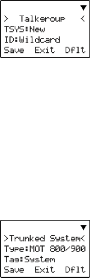
Assuming that you have already entered one or more CONV
objects (which we recommend you do prior to attempting the
entry of the slightly more complicated TGRP object), you should
press the PGM key to place your scanner into Program Mode,
then press the NEW softkey, then press the TGRP softkey. Your
radio display should appear as follows:
In the same way as with the CONV object, this menu of TGRP
parameters can be scrolled up and down to access and enter or
change the various parameters associated with a trunking
talkgroup.
For the purpose of this example, we will assume that you wish to
create a TGRP object for a Motorola Type II 800 MHz trunked
radio system, which is one of the more common types of trunked
radio systems in use. (If this is not the case, we encourage you
to refer to the Detailed Menu Reference section of this manual
for instructions that apply to the type of TSYS you wish to
monitor.)
If necessary, scroll the display so that the flashing cursor is
highlighting the TSYS field, then press the SEL key in the center
of the 5-way pushbutton pad. Your radio!s display should appear
as follows:
We are entering a new Motorola Type II 800 MHz system, so we
can leave the Type: field as-is. It!s a good idea (in fact, a
REALLY good idea, for reasons you will see as you proceed) to
0715 User Manual Page 25
scroll to the Tag: field and enter a name for the system using
the methods previously described for naming your CONV object.
We will use the tag MySystem for this particular example in the
documentation.
Next, scroll to the Frequencies: field to begin entering the
control channel frequencies for the MySystem trunked radio
system. Press the SEL key, and at the Ch01: field you should
enter the first control channel frequency for your Motorola
trunked radio system. Simply key in the frequency including the
decimal point, and press the ENT key or the DONE softkey to
store the control channel frequency. Repeat this step to add any
other control channels used by the system. Typically, a Motorola
trunked radio site or system will have one active control channel
and three backup control channels. You need only enter the
active control channel for the scanner to track the system, but if
the system switches to a backup control channel the scanner will
not receive traffic unless the frequency for the backup control
channel has been entered.
Once you have finished entering the control channels, press the
SAVE softkey. This will store the new TSYS into memory and
return you to the TGRP parameter entry. Your display will now
appear as follows:
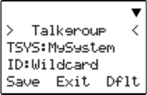
Notice that the system name has changed to reflect the name
you chose when you were entering the parameters for the
trunking system. As you enter this TGRP and other TGRP
objects for this system, you will just specify the system name
here. So, the TSYS parameters for a system need only be
entered once. You simply specify the already-entered TSYS as
needed when building more TGRP objects for the same system.
Scroll down one click to the ID: field. Note that by default, the
trunking talkgroup ID is set to Wildcard. Wildcard is a special
type of TGRP object that allows you to monitor all talkgroup call
traffic on the associated trunked radio system. Wildcard TGRP
objects allow you to quickly find and store new or unknown
talkgroups on a trunked radio system. When a Wildcard TGRP
0715 User Manual Page 26

object is mapped to an active Scan List and scanned, all
talkgroup traffic on the system is monitored, and you have the
option to save or lock out new talkgroups as they appear. You
may wish to save your TGRP object as a Wildcard with no further
changes. If so, just press the SAVE softkey to store your new
TGRP as a wildcard. By default it will take the tag name of
ID: Wildcard.
HINT: Wildcard objects are easier to find and change later if you include an
abbreviated name for the system in the tag field.
If you would rather store a TGRP object for a specific talkgroup
ID on MySystem, just press the number keys to enter the
talkgroup ID of the desired talkgroup, then press the ENT key or
the DONE softkey to store the ID.
HINT: TGRP objects are also used to receive Private/Individual Calls on
trunking systems that support these call types. Simply change the
Type: field from Group to Private. A Wildcard TGRP object with the
Type: field set to Private will monitor all Private/Individual Calls
seen on the system, or you can specify a radio ID to watch for in the
ID: field.
You!ll want to scroll down one more click to the Tag: field and
enter an easy to remember name for your talkgroup that
corresponds with its purpose on the trunked radio system. For
this example, let!s assume that this is a police dispatch
talkgroup, and we would like to use the name “POLICE
DISPATCH” for the tag. Scroll to the Tag: field and press the
SEL key on the 5-way pushbutton pad. Using the text entry
methods that you have previously employed for naming your
CONV and TSYS objects, name your new talkgroup “POLICE
DISPATCH”:
7 1 P
6 3 O
5 3 L
4 3 I
2 3 C
3 2 E
. <space>
3 1 D
4 3 I
7 4 S
7 1 P
0715 User Manual"Page 27

2 1 A
8 1 T
2 3 C
4 2 H
Press ENT or DONE to store the name, then press SAVE to store
the TGRP as a new object. As with the other object types, there
are many other parameters you can edit for the TGRP, but for
now, that!s all you have to do to start monitoring traffic on that
TGRP!
NOTE: Remember, by default all new objects are placed in Scan List 01. For
now, just let your new objects go to the default Scan List 01. Later in
this section we will show you how you can group your objects into
Scan Lists.
Using DUPE to speed up object entry
DUPE is a powerful feature that will help you when entering
multiple objects that have similar characteristics. DUPE is
especially useful when entering multiple TGRP objects that are
hosted on the same trunked radio system, or multiple CONV
objects that have similar parameters or tag names. To use
DUPE, press the PGM key, then scroll to the object that you wish
to duplicate using the !"#$ keys on the 5-way pushbutton
pad. Press the EDIT softkey, then press the DUPE softkey. An
exact copy of the object you selected is created, and the scanner
displays the newly created object menu so you can change the
parameters that need to be changed prior to saving. Be sure to
change the tag name before saving your new object. When
finished, press the SAVE softkey to save the new object.
Try using the DUPE feature now to enter a few more CONV and
TGRP objects before continuing. You might consider using
DUPE on your wildcard TGRP object to make a duplicate, then
set the Type to Private, so you!ll have a TGRP wildcard for
talkgroup calls, and another for private calls.
Basic Scanning Operation
Now that you have entered a few CONV or TGRP objects you
can experiment with Scan and Manual operation.
Activating Scan Mode will cause your scanner to scan through all
Scannable Objects that are members of enabled Scan Lists and
are not locked out. Manual Mode allows you to browse the
0715 User Manual"Page 28

Scannable Objects you have created so you can select just one
to monitor.
To activate Scan Mode, just press the SCAN key on the keypad.
Unless you have explicitly changed Scan List membership, all of
the objects you have entered so far should be in Scan List 01,
and your scanner should begin scanning these objects
immediately when you press the SCAN key. The scanner display
indicates Scan Mode as follows:
Study the two rows under the “Scanning” display. Each space
represents the status of a Scan List in your radio. The top row of
numbers represents Scan Lists 1 through 10, and the bottom row
represents Scan Lists 11 through 20. Unless you have already
enabled other scan lists in your radio, you will only see the
number “1” in the top row. All of the other spaces contain “.”
symbols, which indicates that that these other Scan Lists are
currently not enabled.
If you have included one or more TGRP objects in your
programming, and are within range of the trunked radio system
for those TGRPs, you will see the icon flash periodically while
the radio is scanning. The icon indicates that the scanner is
receiving control channel data from a trunked radio system.
To pause the scanner on an active object so that the scanner
does not resume scanning, press the PSE (Pause) key while the
scanner is stopped on that object, and press SCAN to resume
scanning.
While the scanner is Manual Mode, you can browse through the
stored objects in your scanner and select one object to monitor.
Use the # and $ keys on the 5-way pushbutton pad to scroll
through the objects assigned to the current Scan List. The " and
! keys on the 5-way pushbutton pad are used to browse up and
down through the Scan Lists, respectively. Only Scan Lists that
contain objects are shown when browsing. A quick low-high wrap
beep is played when the scanner reaches the last occupied Scan
List and wraps back to the beginning.
0715 User Manual Page 29
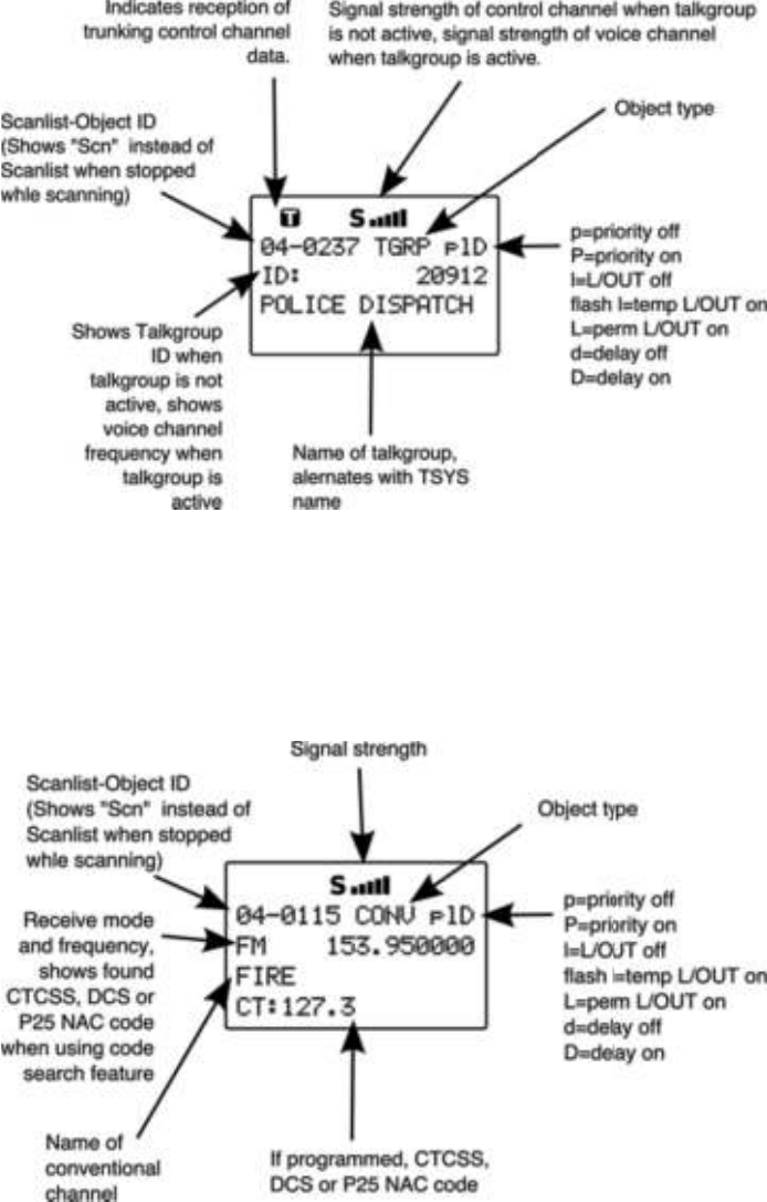
When the scanner is stopped on a TGRP while scanning, or
paused in Manual Mode, the display will appear as follows:
When the scanner is stopped on a conventional channel while
scanning, or while paused in Manual Mode, the display will
appear as follows:
0715 User Manual Page 30

Advanced Startup Topics
Congratulations! Now that you have mastered the creation of
Scannable Objects and how to monitor them using Scan and
Manual Mode, you can move on to some more advanced startup
topics.
This Advanced Startup Topics section of the manual will provide
you with more basic information about how you can create other
types of Scannable Objects, and how you can group your
Scannable Objects into different Scan Lists and work with the
Scan Lists to quickly enable or disable groups of objects that you
want to monitor. You can also read the Detailed Menu Reference
section of this manual to learn more about the different object
types and their parameters, and how to perform more advanced
operations with your scanner.
About Object Numbering
Your 0715 is different from other types of scanners in how it
stores your scannable objects in memory. Instead of fixed
channels and banks, objects are stored in the first available block
of free memory and assigned an Object ID. The Object ID is the
“address” where the object is stored in memory. You can use this
address to quickly access your stored objects when in the
Manual Mode and PGM modes. Press MAN or PGM, then key
the Object ID using the numeric keypad, then press ENT to go to
that object.
The Object ID is displayed as a four digit number in the upper
right-hand corner of the display whenever an object is selected in
Manual Mode and PGM modes, and when the scanner stops on
an active object while scanning. Additionally, the current Scan
List number is displayed prior to the Object ID when an object is
selected in Manual Mode or PGM mode, i.e.,
10-0348
indicates Object ID 0348 in Scan List 10.
Search Object Types
A very powerful feature of your 0715 is the ability to define
different types frequency searches and process them while
scanning. Frequency searches are just another type of
Scannable Object in the hierarchy of the radio!s memory
organization, so they can be manipulated and scanned in the
same manner as conventional channels and trunking talkgroups.
0715 User Manual"Page 31
There are several different types of frequency searches available
in your scanner.
Limit Search Object (LMIT)
A Limit Search Object (LMIT) is a search object that stores the
parameters necessary for the radio to search each frequency
within a lower and an upper limit for activity. A LMIT object can be
used for standalone searching – the radio just searches and
stops when activity is detected on a frequency, or for searching
that is performed while the radio is scanning. The radio treats
LMIT objects just like any other Scannable Object when in Scan
Mode. If you create a LMIT object, assign it to a Scan List and
press the SCAN key, the radio will check for activity on all the
Scannable Objects – TGRP objects, CONV objects, and even
LMIT objects. An example of when this might be handy would be
when you want to scan for activity on a collection of TGRP and
CONV objects, then run through a range of frequencies to look
for activity there, such as the entire 2 meter amateur radio band
or the entire VHF marine radio band. When used in Scan Mode,
this capability is best suited for small ranges of frequencies that
contain more frequencies than practical to program as individual
channels. Any size range can be used, but larger ranges that
take more time to search will increase the chances of missed
activity on other object types.
Essential Limit Search parameters
Much like the other object types, there are only a few parameters
that are essential in order for a search range to function correctly.
The FrLO: and FrHi: lower and upper frequency limits must be
specified, so the scanner will know where to begin the search,
and where to end the search and start again. The Mode: must
be set properly, although by default the scanner will automatically
choose the receive mode that most likely applies to the active
frequency as the search proceeds. And again, we recommend
that you give the LMIT object a name in the Tag: field so that
you can easily find or identify it later.
To create a new LMIT object, press PGM to place your scanner
into Program Mode, then press the SRCH softkey to view the
available Search types, then press the LMIT softkey. Use the
data entry methods you have already learned for CONV and
TGRP object setup to specify the FrLO: and FrHi: limits, and
provide a name for your search in the Tag: field. When finished,
press the Save softkey to store your LMIT search as a new
object.
0715 User Manual"Page 32
Once your LMIT object is saved, you can use it while scanning,
or launch the LMIT search by itself by pressing the SRCH softkey
after navigating to the LMIT object in Manual Mode.
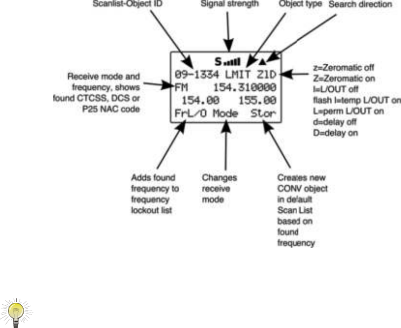
When the LMIT search stops on an active frequency, the display
will appear as follows:
HINT: It can take some time for the 0715 to process all of the
frequencies in a LMIT search. You can experiment with different size
frequency ranges to find a LMIT search setup that does not interfere
excessively with scanning of other object types.
Spectrum Sweeper Object (SWPR)
A Spectrum Sweeper Object (SWPR) is a record that stores the
parameters necessary for the radio to rapidly sweep a range of
frequencies for strong signals from nearby transmitters. A SWPR
object can be used for standalone operation – the radio just
sweeps and stops when activity is detected, or for sweeping that
is performed while the radio is scanning. The radio treats SWPR
objects just like any other Scannable Object when in Scan Mode.
If you create a SWPR object, assign it to a Scan List and press
the SCAN key, the radio will check for activity on all the enabled
Scannable Objects – TGRP objects, CONV objects, LMIT objects
and SWPR objects. An example of when this might be handy
0715 User Manual Page 33
would be when you want to scan for activity on a collection of
TGRP and CONV objects, then do a quick sweep for
transmissions from nearby transmitters.
Essential Spectrum Sweeper parameters
Like every other object type, there are certain parameters in a
SWPR record that are essential in order for the SWPR object to
function correctly. By default, a newly created SWPR object is
ready to go without any changes. In its default configuration, the
SWPR object will sweep through all of the important land mobile
radio bands and look for strong signal activity from nearby
transmitters. As you become more familiar with SWPR operation,
you may wish to include or exclude some bands in your sweeps
to check other frequency ranges or to limit the amount of time the
scanner spends sweeping frequency ranges where local
transmitter activity is less likely. This will speed up operation, and
when used while scanning, will allow the radio to return to
scanning for activity on CONV, TGRP and other enabled objects.
To create a new SWPR object, press PGM to place your scanner
into Program Mode, then press the SRCH softkey to view the
available Search types, then press the SWPR softkey. By default
the SWPR parameters are set for a general purpose sweep of all
important land mobile radio bands. Optionally, you may wish to
toggle the Type: field from All Bands to Public Safety by
pressing " on the 5-way pushbutton pad. When Public Safety is
selected, the frequency sweep will be limited to those frequency
ranges typically used for Public Safety communications. Note
that other radio services also use these ranges, so don!t be
surprised if you occasionally hear activity that is not Public Safety
related. Be sure to provide a name for your SWPR object in the
Tag: field. When finished, press the Save softkey to store your
SWPR search as a new object.
Once your SWPR object is saved, you can use it while scanning,
or launch the the Spectrum Sweeper object by itself by pressing
the SWPR softkey after navigating to the SWPR object in Manual
Mode.
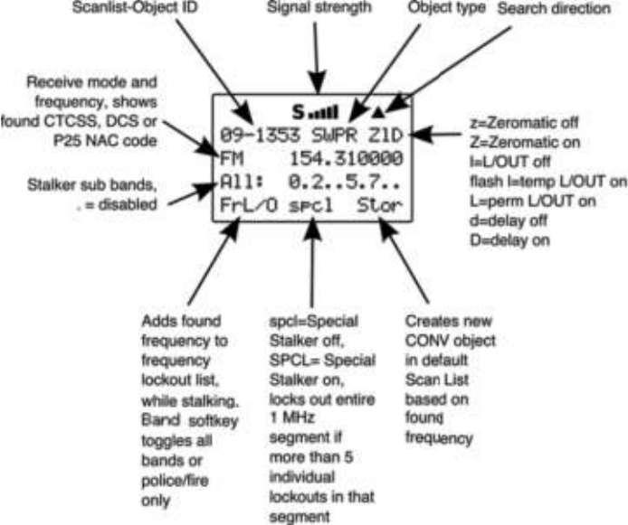
When the SWPR object stops on an active frequency, the display
will appear as follows:
0715 User Manual"Page 34
Service Search Object (SRVC)
A Service Search Object (SRVC) is similar to a LMIT search but
is optimized for a specific radio service, and can search for
activity associated with a type of service across multiple
frequency bands.
Essential Service Search parameters
The only critical parameter needed for a Service Search to
function is the service type. When you set up a Service Search,
you will want to specify the type of service that you wish to
search.
To create a new SRVC object, press PGM to place your scanner
into Program Mode, then press the SRCH softkey to view the
available Search types, then press the SRVC softkey. Scroll to
the Srvc: field and select the type of search you want to define
using the !" keys on the 5-way pushbutton pad. Service types
include Public Safety, Aircraft, Amateur, CB, Marine, FRS/GMRS/
MURS/DOT and Railroad, and provide frequency coverage as
follows:
0715 User Manual Page 35
Public Safety (PubSafety) - Searches commonly used public
safety frequencies. Groups are as follows:
"0: 33.4-46.5 MHz" " VHF Low Band
"1: 151-170 MHz" " VHF High Band
"2: 453-467 MHz" " UHF Band
"3: 764-806 MHz" " 700 MHz Band
"4: 851-869 MHz" " 800 MHz Band
Aircraft - Searches civilian and military air frequencies. Groups
are as follows:
"0: 108-118 MHz Navigation
"1: 118-137 MHz Civilian Voice
"2: 138-150 MHz Military Voice (excludes 2m Amateur)
"3: 225-400 MHz Military Voice
Ham - Searches amateur radio frequencies. Groups are as
follows:
"0: 28.0-29.7 MHz"10m Band
"1: 50-54 MHz"6m Band
"2: 144-148 MHz"2m Band
"3: 222-225 MHz"1.25cm Band"
"4: 420-450 MHz"70cm Band
"5: 902-928 MHz"33cm Band
"6: 1240-1300 MHz"23cm Band
CB - Searches the Citizens Band radio frequencies
Marine - Searches the VHF-FM marine radio band
FRS/GMRS/MURS/DOT/STAR (F/G/MURS) - Searches the
FRS, GMRS, MURS, DOT and STAR radio frequencies
Railroad - searches the Association of American Railroads
(AAR) VHF railroad frequencies used in the US and Canada
When finished, press the Save softkey to store your SRVC
search as a new object.
Once your SRVC object is saved, you can use it while scanning,
or launch the SRVC search by itself by pressing the SRCH
softkey after navigating to the SRVC object in Manual Mode.
When the SRVC search stops on an active frequency, the display
will appear as follows:
0715 User Manual"Page 36
Now, take a few moments to practice setting up each of the
different search object types by experimenting and creating
some SRVC, LMIT and SWPR objects. Remember that there is
context sensitive help available for each menu item in the object
menus. Just press FUNC, then SEL to view the help, and SEL
again to exit the help screen.
These are just a few of the many ways you can incorporate
different types of search objects in your Scan List configurations.
and, just a few of the many ways that each of the individual
search types can be configured to your preferences and needs.
Be sure to refer to the Detailed Menu Reference section of the
manual for detailed information for each of the search object
types.
Grouping Objects in Scan Lists
By default, new objects are automatically assigned to Scan List
01. Now that you have entered a variety of new objects that are,
by default, members of Scan List 01, you may want to separate
these objects into separate Scan Lists so that you can easily
enable or disable groups of objects as needed depending on
what you want to scan. There are 20 regular Scan Lists
available, a special “FAV” Scan List for one-button access to your
favorite Scannable Objects, and a Skywarn Scan List.
0715 User Manual Page 37
Although Scan Lists are similar to the “banks” that are used in
older bank/channel scanner designs, you will find that they are
much more powerful and flexible than “banks”. The number of
objects that can be grouped in a Scan List is limited only by the
scanner!s memory, and single objects can be members of
multiple Scan Lists without creating duplicate versions of those
objects and manually placing them in each Scan List where you
want them included.
You can also mix and match different object types in scan lists as
you see fit. Feel free to group your objects in the manner that
best suits your listening style. If you choose to group your objects
by geographical area, and find that the best set of Scannable
Objects for your area includes a mix of trunked talkgroups and
conventional channels, go right ahead and put them all in the
same scan list. There are no limitations as to the type of objects
that can exist together in the same scan list.
How you group objects in Scan Lists is entirely up to you! Here
are some examples of how objects can be grouped:
Geographically
You may wish to group your Scannable Objects according to the
areas where they are used. For example, assume that you
routinely travel to another town to visit family. You can assign the
channels and talkgroups for fire and police services around your
home to one Scan List, and those that are located where your
family lives in another. When you travel to visit your family, you
can no longer hear the Scannable Objects assigned to your
home Scan List, so you disable that Scan List and enable the
Scan List that contains the channels and talkgroups that are in
use in your family!s town.
By trunking system
It is possible to assign any combination of object types to any
Scan List. However, you may wish to assign TGRP objects
associated with specific trunked radio systems to specific Scan
Lists, so you can easily enable or disable monitoring of each
system by enabling or disabling the associated Scan List.
By object type
It may be desirable to segregate object types by assigning them
to specific Scan Lists. For example, you can assign a group of
LMIT or SRVC searches to a single Scan List, and easily activate
or deactivate searching on those objects by enabling or disabling
0715 User Manual"Page 38

the associated Scan List. You may wish to place your wildcard
TGRP group call or private call objects in a separate Scan List.
By application
You can group objects by their application. For example, you
may wish to place all law enforcement related objects for your
area in one Scan List, all fire and rescue objects in another, and
all business related objects in yet another Scan List. Racing fans
may wish to group objects for different cars, drivers, teams and
tracks into separate scan lists.
Mapping Objects to Scan Lists
By default, every new object you create is mapped to be a
member of Scan List 01. Scan List membership is defined in an
object!s parameters menu and is typically found at the end of the
menu.
To change Scan List membership when creating a new object,
scroll down to the Scan Lists: parameter in the object!s menu
before saving the object. With the Scan Lists: field
highlighted, use the " on the 5-way pushbutton pad to scroll
through the Scan Lists, and use the SEL button to toggle
membership for a Scan List on or off. The asterisk (*) next to the
Scan List number indicates that the object is a member of that
Scan List. Press the Save softkey to save the modified object.
To change Scan List membership for an existing object, press
the PGM key. Use the !"#$ keys on the 5-way pushbutton
pad to scroll to the existing object that you wish to change, then
press the EDIT softkey. Press the CURR softkey to edit the
current object.
NOTE: Remember, when browsing objects in Manual or Program Mode, the
arrow keys on the 5-way pushbutton pad operate as follows:
#: navigates “up” through the objects assigned to the
current Scan List
$: navigates “down” through the objects assigned to the
current Scan List
!: navigates “up” through the active Scan Lists in the radio
": navigates “down” through the active Scan Lists in the
radio
0715 User Manual"Page 39
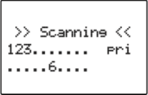
Scroll down in the object!s parameters menu to the Scan
Lists: field. With the Scan Lists: field highlighted, use the
" on the 5-way pushbutton pad to scroll through the Scan Lists,
and use the SEL button to toggle membership for a Scan List on
or off. The asterisk (*) next to the Scan List number indicates
that the object is a member of that Scan List. Press the Save
softkey to save the modified object.
Enabling and disabling Scan Lists
Scan Lists may be enabled or disabled while actively scanning,
or by accessing the individual Scan List in the Global Settings
(GLOB) menu.
To toggle a Scan List!s enabled/disabled status while scanning,
press the numeric key that corresponds with the Scan List you
wish to toggle. For example, pressing 4 while scanning will
toggle the state of Scan List 04 from enabled to disabled, or vice
versa if the Scan List is already disabled. To toggle the enabled/
disabled status for Scan Lists 11-20, press FUNC, then press a
number key, i.e., press FUNC 3 to toggle the status of Scan List
13. If you enable a Scan List that has no assigned objects, the
number for that scan list will flash in the display while the
scanner is scanning.
For example, when Scan Lists 1, 2, 3 and 16 are enabled, the
display will appear as follows while scanning:
To toggle a Scan List!s status from the Global Settings menu,
press PGM to enter Program Mode, then press the GLOB softkey.
Scroll down to the Scan Lists: item and press the SEL key on
the 5-way pushbutton pad. Scroll to the Scan List you wish to
change and press the SEL key again, then at the Enabled:
setting press the ! or " on the 5-way pushbutton pad to toggle
the Scan List on or off. Press the SAVE softkey to save settings
for that Scan List, then press SAVE again to confirm your global
changes and exit the GLOB menu.
0715 User Manual Page 40

HINT: You can also change the name of your Scan Lists in the GLOB
menu. Use the text entry techniques previously discussed for
entering object tag names.
If you inadvertently store an object with no Scan List
mappings, the object will be placed in a special “NS” Scan
List that can be accessed using the !" keys while in
Manual Mode or PGM mode. Once you scroll to the NS
scan list, you can use the #$ keys to scroll to the objects
found there and edit the Scan List setting by pressing the PGM
key, then the EDIT and CURR softkeys to see the object!s menu.
Other Startup Topics
Here are some more startup topics that will help you get more
enjoyment out of your 0715 as you become more experienced
with its operation.
Finding Stored Objects Easily
The 0715!s browse feature makes it easy to scroll to the Scan
Lists and Scannable Objects you have created, using the
!"#$ keys on the 5-way pushbutton pad while the scanner is
in PGM or Manual Mode. Here are some more methods you can
use to find stored objects quickly.
Searching For Objects Using FIND
Your 0715 provides a very useful FIND feature that allows you to
search all objects for a text string that you specify. FIND
searches for your specified text in the following places:
•In TGRP objects, the ID field and the Tag field
•In CONV objects, the Frequency field and the Tag field
•In TSYS, LMIT, SRVC and SWPR objects, the Tag field
To use FIND, press the PGM key, then press the EDIT softkey.
Press the FIND softkey, then enter the text string you wish to
search for.
Filtering By Object Type
When browsing objects in PGM mode, you can filter the objects
that are displayed by their type.
Press the PGM key on the keypad, then press the EDIT softkey.
Press the ! or " keys on the 5-way pushbutton pad to scroll the
Edit softkeys to display the filter softkeys. The filter softkeys are
as follows:
0715 User Manual"Page 41
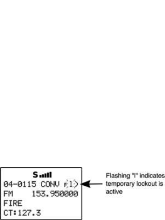
CONV
TGRP
TSYS
SRCH
SWPR
To filter browse for a specific type of object, press the softkey
that corresponds with that object type. For example, press the
CONV softkey, then use the !"#$ keys on the 5-way
pushbutton pad to browse only conventional objects.
Object Lockout
The L/OUT key is used to lock out objects. When an object is
locked out, traffic is not received on that object until it is
unlocked.
Four types of lockout functions are available in the 0715,
temporary lockout, permanent lockout, search lockout and
talkgroup lockout.
Temporary Lockout
Temporary lockout locks out an object until the scanner is turned
off. When the scanner is powered on again, all objects that have
been temporarily locked out are restored.
By default, the L/OUT key activates temporary lockout when
pressed. If desired, you can change the function of the L/OUT
key in the GLOB radio wide settings by pressing PGM, then the
GLOB softkey. Scroll to the TLO=FUNC L/O setting and press the
6 key to toggle the setting to YES to have the L/OUT key function
as a permanent lockout instead of temporary lockout.
To apply temporary lockout to an object, press the L/OUT key
while the scanner is stopped on that object during scan
operation, or navigate to an object using the 5-way pushbutton
pad while in Manual Mode or PGM mode and press the L/OUT
key. The lowercase “l” in the display flashes to indicate that
temporary lockout is applied to the object:
0715 User Manual Page 42
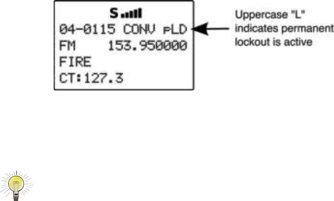
If you wish to remove temporary lockout from a single object,
navigate to the object using the 5-way pushbutton pad while in
Manual Mode or PGM mode and press the L/OUT key again.
Permanent Lockout
Permanent lockout locks out an object until it is explicitly
unlocked by you. No traffic will be received on the locked out
object while permanent lockout is active.
To apply permanent lockout to an object, press FUNC, then the L/
OUT key while the scanner is stopped on that object during scan
operation, or navigate to an object using the 5-way pushbutton
pad while in Manual Mode or PGM mode and press FUNC, then
the L/OUT key. The lowercase “l” in the display changes to
uppercase to indicate that permanent lockout is applied to the
object:
If you wish to remove permanent lockout from an object,
navigate to the object using the 5-way pushbutton pad while in
Manual Mode or PGM mode and press FUNC, then L/OUT again.
HINT: You can also toggle lockout anytime you are viewing an object menu
in Program mode by pressing L/OUT.
Search Lockout
Search lockout works with certain search objects, including
LMIT searches, some SRVC searches, and SWPR objects.
Frequency lockout is used to lock out undesired frequencies that
are found during searches.
To apply search lockout during a search, press the FrL/O
softkey while the scanner is stopped on the undesired frequency:
0715 User Manual Page 43
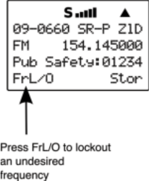
Applying search lockout to an undesired frequency adds that
frequency to the Search Lockout List, a list of frequencies that
the scanner ignores when performing searches or during
Spectrum Sweeper operations. You can edit or clear the Search
Lockout List by following these steps:
Press PGM
Press the GLOB softkey
Scroll down to the SRCH L/Outs: item and press SEL
Scroll to the frequencies you wish to remove from the lockout list
and press the Del softkey to remove them from the list.
Scroll to an empty spot and enter any frequency you wish to
manually add to the list.
Press FUNC, then the Del softkey to clear the entire list.
Talkgroup Lockout
Talkgroup lockout is similar to search lockout, as it allows you to
lockout undesired talkgroups while searching for new talkgroup
activity with wildcard TGRP objects.
To apply lockout on an undesired wildcard hit, press the lockout
during a search, press the TGL/O softkey while the scanner is
stopped on the undesired talkgroup:
0715 User Manual Page 44
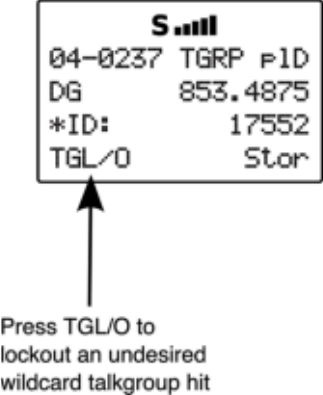
Applying wildcard lockout to an undesired talkgroup creates a
new TGRP object in the same scan list as the wildcard TGRP,
then applies permanent lockout to the new TGRP object, so that
will be ignored in the future by the scanner when scanning the
wildcard talkgroup. To unlock or edit talkgroups locked out using
the wildcard lockout feature, press PGM, then navigate to the
object using the 5-way pushbutton pad. Press FUNC, then L/OUT
to remove permanent lockout from the talkgroup. Press FUNC,
then CL to delete the TGRP object from the scanner. Press the
EDIT, then the CURR softkey to edit and save the TGRP object.
Deleting Objects
Objects that you know longer need to use can easily be deleted
from the 0715!s memory, making room for new objects.
To delete an object, press PGM, then use the !"#$ keys to
navigate to the object you wish to delete. Press FUNC CL to
delete the object. The scanner will ask you to confirm the delete
command before removing the object from the scanner!s
memory.
Priority Scan
Your 0715 scanner features Priority Scan operation for CONV
and TGRP objects. When Priority Scan is active, increased
priority is given to objects that have their Priority mode set to
ON.
Turning Object Priority On or Off
Priority for CONV and TGRP objects can be toggled on or off
using the following methods:
0715 User Manual Page 45
Press the PRI key when the scanner stops on the object while it
is active. The plD indicator in the object display will show p for
Object Priority Off, and P for Object Priority On.
Browse to an object in Manual Mode or PGM mode, then press
the PRI key to toggle Object Priority on or off. The plD indicator
in the object display will show p for Object Priority Off, and P for
Object Priority On.
Browse to an object in PGM mode. Press the EDIT, then CURR
softkeys. Use the $ key to scroll to the Priority setting. Use
the ! or " keys to toggle Priority On or Off.
When creating a new object, before saving the object scroll to
the Priority setting. Use the ! or " keys to toggle
Priority On or Off.
Turning Priority Scan Mode On or Off
While the radio is scanning, press FUNC, then PRI to toggle
Priority Scan On or Off. Priority Scan status is shown in the man
Scanning status display. PRI indicates that Priority Scan mode is
on, and pri indicates that Priority Scan mode is off.
CONV Priority Scan
When Object Priority is set to Yes for one or more CONV objects,
the scanner will sample the CONV objects for activity periodically
while scanning and monitoring other objects.
This sampling will cause a brief muting of received audio when it
occurs while another object is active.
The more CONV objects are set for Priority, the longer this audio
muting will be, since it takes a certain amount of time to sample
each Priority CONV object for activity.
TGRP Priority Scan
When Object Priority is set to Yes for one or more TGRP objects,
the scanner will give those TGRPs priority over other TGRPs
while checking a particular trunking system for activity. TGRPs
configured for Priority are checked for activity before any other
TGRPs are checked, and during the reply delay time after non-
priority TGRP calls.
Additionally, your 0715 decodes the subaudible priority data that
is present on analog Motorola talkgroup calls, and will switch to a
0715 User Manual"Page 46
priority talkgroup when the data for that talkgroup is found in the
subaudible priority data.
Audible Alarms and the ALERT LED
Your 0715 features a very powerful ALERT LED with Audible
Alarm capability that allows you to set different types of visual
and audible notifications for the different types of objects you
create.
You may have noticed that the menus for each object you create
include various settings for LED, Backlight and Alarm. You can
use these settings to design custom visual and/or audible alarms
that are triggered when activity is detected on the specified
Scannable Object.
Audible Alarm and ALERT LED Settings""
Each object you create has the following ALERT LED and
Audible Alarm settings:
LED Mode: Solid or Flash controls whether the LED
remains on solid or flashes when the object is active.
LED Color: 0-7 sets the color of the LED. By default, color 0
is used for LED off. You can change the LED colors in the Global
Settings menu.
Latch LED keeps the LED on after activity on the object is
finished. This is useful in cases where you need to know if an
object was active while you were away from the scanner.
Backlight: Off, On, Flash controls whether the backlight
remains off, comes on solid or flashes when the object is active.
Alarm: None, Chirp, Hi-Lo, Alert, Ring, 2-
Chirp, Fast Hi-Lo, DTMF # are used to set audible
alarms that play each time activity is found on the object.
ALERT LED with Audible Alarm Examples
Here are some examples of when you may wish to use the
ALERT LED with Audible Alarm capability:
•You have programmed a Talkgroup Wildcard in for a trunked
radio system you monitor in order to find new talkgroups. You
can use an Audible Alarm to alert you when the radio receives
a wildcard hit, and turn on the backlight so that you can read
the display and operate the keypad to save or lock out the new
talkgroup.
0715 User Manual"Page 47
•You have programmed you favorite amateur radio repeater in
and wish to be alerted when a QSO begins. You can use an
Audible Alarm with one of the shorter alarms (Chirp, 2-Chirp,
Fast Hi-Lo or DTMF #) to provide this indication without
covering the traffic in the QSO.
•You have included a Spectrum Sweeper object in your scan
configuration so that you can find nearby strong transmitters
while you are scanning. You can use an Audible Alarm to alert
you when the radio receives a Spectrum Sweeper hit, and turn
on the backlight so that you can read the display and operate
the keypad to save or lock out the new frequency. This
technique is also useful for TGRP wildcards.
•You wish to assign different LED colors to different types of
public safety agencies, i.e., red for fire, rescue and EMS, blue
for law enforcement, yellow for emergency management, and
so on. When there is activity you can tell if it is related to law
enforcement, fire/rescue and EMS or emergency management
at a glance, even if the transmission is short or difficult to copy.
The possibilities for the ALERT LED with Audible Alarm capability
are limited only by your imagination.
Dedicated search modes
In addition to its powerful ability to store different types of
frequency searches as objects, your scanner provides fast
access to dedicated frequency search modes that allow you to
execute searches or run the Spectrum Sweeper without having
to go through the process of setting up and saving a search
object. This is handy for those times where you need to run a
search quickly. Dedicated search modes do not create new
search objects or use previously created search objects.
Using Dedicated Spectrum Sweeper (SWPR) Mode
Dedicated SWPR mode lets you access and run the Spectrum
Sweeper easily and quickly. Press FUNC SCAN while in the
Manual, Program or Scan Modes to access the Spectrum
Sweeper dedicated mode.
0715 User Manual"Page 48
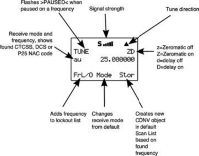
Operation of the dedicated Spectrum Sweeper mode is almost
identical to that of the object mode, with one exception. When
running the Spectrum Sweeper as a scannable object, you must
use the object menu to enable or disable the Spectrum Sweeper
sub-bands when operating in Scan Mode. When dedicated
Spectrum Sweeper mode is used, you may press the numeric
key on the keypad that corresponds with the sub-band you wish
to enable or disable. Disabling a sub-band will cause the
Spectrum Sweeper system to skip the frequencies within that
sub-band as it performs its sweeps. The sub-bands are defined
as follows:
0: 25-54 MHz VHF Low Band
1: 108-137 MHz VHF Aircraft Band
2: 137-174 MHz VHF High Band
3: 216-300 MHz 220 MHz Commercial/Amateur Band
4: 300-406 MHz UHF Military Air Band
5: 406-470 MHz UHF Band
6: 470-512 MHz UHF-T Band
7: 764-806 MHz 700 MHz Band
8: 806-869 MHz 800 MHz Band
9: 896-1300 MHz 900 MHz Band, 23 cm Amateur Band
In Public Safety, the sub bands are defined as follows:
0715 User Manual Page 49

0: 33.4-46.5 MHz VHF Low Band
1: 151-170 MHz VHF High Band
2: 453-467 MHz UHF Band
3: 764-806 MHz 700 MHz Band
4: 851-869 MHz 800 MHz Band
Using dedicated TUNE mode
Your scanner!s dedicated TUNE mode provides you with the
ability to quickly enter any frequency and monitor that frequency
for transmissions, or search up or down from that frequency for
activity.
To enter TUNE mode, press the TUNE key on the keypad. The
scanner displays the TUNE screen.
By default, TUNE mode is paused when first activated. Press
PSE to begin searching from the current frequency.
Press the # or $ keys on the 5-way pushbutton pad to change
the search direction.
Press the FrL/O softkey to add a found frequency to the lockout
list.
0715 User Manual Page 50
Press the MODE softkey to change the receive mode (AM, FM,
NFM) from the default for the current frequency range (au).
Press STOR to create a new CONV object using the found
frequency.
Use the keypad to enter a new frequency, and press ENT to
make that the TUNE frequency.
Using FUNC TUNE from any other mode will load the last active
frequency from the other mode into TUNE. For example,
pressing FUNC TUNE while parked on a trunked radio system will
load the control channel frequency into the TUNE mode if the
control channel frequency is the last frequency that the scanner
checked while scanning.
Dedicated TUNE mode will always check for the presence of
encoded squelch and digital modulation each time it finds an
active frequency. If a valid encoded squelch code is found, it will
be stored automatically when you press STOR to create a new
CONV object.
Using dedicated Limit and Service search modes
The SRCH key provides immediate access to the dedicated
search modes of your 0715. Pressing the SRCH key cycles
through each search mode in this order: Limit, Railroad, Public
Safety, Aircraft, Ham, CB, Marine, and FRS/GMRS/MURS/DOT.
LMIT Search Mode
Your scanner!s dedicated LMIT search mode provides you with
the ability to create a limit search with a search frequency range
between upper and lower limit frequencies that you specify and
perform the limit search directly without creating a new LMIT
object. You can then monitor that frequency range for
transmissions.
To enter LMIT mode, press the SRCH key on the keypad
repeatedly until the display indicates LMIT search as follows:
0715 User Manual"Page 51
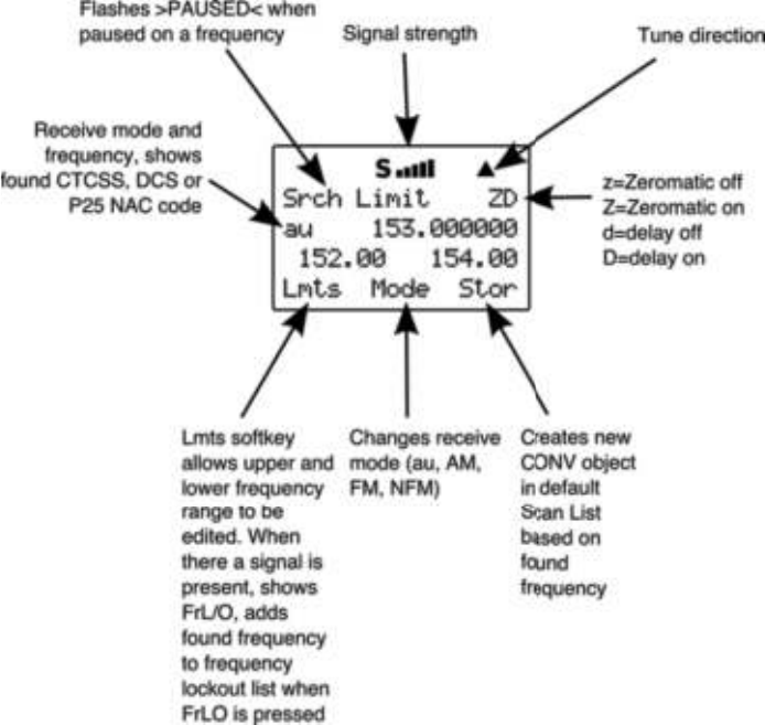
Use the Lmts softkey to set the lower and upper frequency limits
for your limit search.
Press the # or $ keys on the 5-way pushbutton pad to change
the search direction.
Press the MODE softkey to change the receive mode (AM, FM,
NFM) from the default for the current frequency range (au).
Press the FrL/O softkey to add a found frequency to the lockout
list.
Press the STOR softkey to create a new CONV object using the
found frequency.
Using dedicated SRVC mode
Your scanner!s dedicated SRVC search modes provide you with
the ability to instantly access each of the scanner!s service
search ranges without creating a new SRVC object.
0715 User Manual Page 52
To activate dedicated SRVC search mode, press the SRCH key
on the keypad repeatedly until the desired service search is
indicated on the display. The following service searches are
available:
Railroad - searches the Association of American Railroads
(AAR) VHF railroad frequencies used in the US and Canada
Public Safety (PubSafety) - Searches commonly used public
safety frequencies. Groups are as follows:
"0: 33.4-46.5 MHz" " VHF Low Band
"1: 151-170 MHz" " VHF High Band
"2: 453-467 MHz" " UHF Band
"3: 764-806 MHz" " 700 MHz Band
"4: 851-869 MHz" " 800 MHz Band
Aircraft - Searches civilian and military air frequencies. Groups
are as follows:
"0: 108-118 MHz Navigation
"1: 118-137 MHz Civilian Voice
"2: 138-150 MHz Military Voice (excludes 2m Amateur)
"3: 225-400 MHz Military Voice
Ham - Searches amateur radio frequencies. Groups are as
follows:
"0: 28.0-29.7 MHz"10m Band
"1: 50-54 MHz"6m Band
"2: 144-148 MHz"2m Band
"3: 222-225 MHz"1.25cm Band"
"4: 420-450 MHz"70cm Band
"5: 902-928 MHz"33cm Band
"6: 1240-1300 MHz"23cm Band
CB - Searches the citizen!s band radio frequencies
Marine - Searches the VHF-FM marine radio band
FRS/GMRS/MURS/DOT/STAR (F/G/MURS) - Searches the
FRS, GMRS, MURS, DOT and STAR radio frequencies
0715 User Manual"Page 53
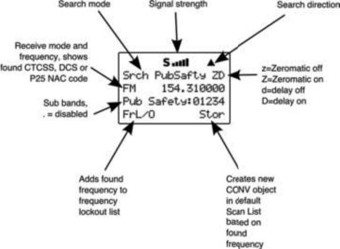
Use the numeric keypad to toggle the sub bands on and off while
searching.
Press the # or $ keys on the 5-way pushbutton pad to change
the search direction.
Press the FrL/O softkey to add a found frequency to the lockout
list.
Press the STOR softkey to create a new CONV object using the
found frequency.
Using Weather Modes
Your 0715 also functions as a powerful weather alert receiver.
There are three modes of weather alert operation available to
you.
Weather Radio Mode
Weather radio mode allows you to receive weather broadcasts
from your local weather service anytime of the day.
To use weather radio mode, simply press the WX button on the
keypad. The scanner will quickly scan and lock on to the first
active weather radio frequency it receives. You can use the # or
$ keys on the 5-way pushbutton pad to force the radio to look
for other weather radio transmitters. It is generally best to select
0715 User Manual Page 54
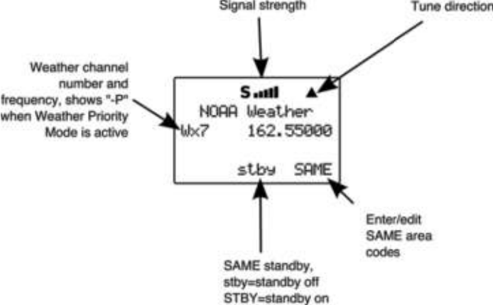
the weather radio transmitter that provides you with the strongest
signal. You can use the signal meter to help you chose the best
weather radio transmitter for your area. While operating in
Weather Radio Mode, your scanner will alert on SAME
messages that match the SAME location codes you have
entered, or all SAME messages if you do not enter any SAME
location codes.
Weather Priority Mode
Weather Priority mode samples the specified weather frequency
periodically while scanning to see if the All Hazards Warning Alert
Tone (WAT) is present. If the WAT is present, the scanner will
sound an alarm and tune to the specified weather frequency to
monitor the nature of the alert.
To activate Weather Priority Mode, follow the steps above listed
above in Weather Radio Mode to find the strongest weather
radio transmitter for your area. Once the radio is tuned to the
strongest weather radio transmitter for your location, press the
PRI key on the keypad. When in Scan Mode, the radio will check
the specified weather frequency periodically for the Warning Alert
Tone (WAT). If WAT is found, the radio will sound an alarm and
monitor the weather alert audio.
SAME Standby Mode
SAME Standby Mode locks the radio on the specified weather
frequency, where it waits to receive a Specific Area Message
0715 User Manual Page 55
Encoding (SAME) alert that corresponds with a SAME location
code that you have previously entered. If there is a match
between a sent SAME location code and one that you have
previously stored, the scanner will sound an alarm, display the
alert type, and monitor the nature of the alert.
To activate SAME Standby Mode, first you should provide at
least one SAME location code for your city, county or state. By
default, SAME mode will alert on any SAME message received if
no SAME location codes are entered. A list of SAME location
codes can be found online at this web site:
http://www.nws.noaa.gov/nwr/indexnw.htm#sametable
In addition to the code for your location, you may wish to enter
additional codes for surrounding areas and any other areas of
interest so that you can receive advance warning of adverse or
dangerous weather that may be headed in your direction.
Unlike other weather alert radios, your scanner features a
powerful SAME wildcard feature that allows you to set the radio
to alarm on partial matches of the location code. For example,
the SAME location code for Dallas, TX is 048113, which can be
broken down as follows:
0 represents a subdivision within a county, and is typically not
used.
48 is the State code for Texas
113 is the County code for Dallas County
Entering the entire 048113 code will cause the radio to receive all
SAME alerts that match the code for Dallas County.
Suppose you wanted to receive any alert for any county in the
entire state (provided that the alert is sent by your local NWS
transmitter). Using the wildcard feature you can enter a SAME
area code as follows:
*48***
This tells the radio to alert on any SAME message with a location
code that matches 48 for the state of Texas.
Your scanner also allows you to specify the event code. The
default alert code is “***”, which is best for most general purpose
0715 User Manual"Page 56
weather alert monitoring purposes. A list of event codes can be
found at this web site:
http://www.weather.gov/os/eas_codes.shtml
Each SAME location/event code storage location can be
configured for Entry ON/OFF and Lockout ON/OFF.
When a SAME location/event code storage location is set for
Entry ON, the radio will process the SAME location/event code
that is stored there. When a SAME location/event code storage
location is set for Entry OFF, that SAME location and event code
will be ignored.
When a SAME location/event code storage location is set for
Entry ON and Lockout ON, the radio will process the SAME
location/event code that is stored there, and will lock out the
specified event code. A SAME location/event code storage
location set for Entry: OFF and Lockout: ON will not be
processed, because Entry is set to OFF. In case of a conflict (i.e.,
two identical codes and events are entered, and one is locked
out), the locked out entry will take precedence.
SAME Entry Examples
Using the Dallas County, TX example above:
SAME Entry 1:
Code: 048113
Event: ***
Entry: ON
Lockout: OFF
SAME Entries 2-10:
Code: ******
Event: ***
Entry: OFF
Lockout: OFF
The above entry for 048113 will receive all SAME messages for
048113.
SAME Entry 1:
Code: 048113
Event: ***
Entry: ON
Lockout: OFF
0715 User Manual"Page 57
SAME Entry 2:
Code: 048113
Event: RWT
Entry: ON
Lockout: ON
The above combination of entries for 048113 will receive all
SAME messages for 048113, except the Required Weekly Test
(RWT) message, since the second entry is ON, with lockout ON,
and with RWT in the event field.
SAME Entry 1:
Code: 048113
Event: ***
Entry: ON
Lockout: OFF
SAME Entry 2:
Code: 048113
Event: ***
Entry: ON
Lockout: ON
The above combination of entries for 048113 will not receive any
SAME messages for 048113, since the second entry is ON, with
lockout ON, and with *** (all events wildcard) in the event field.
The entry lockout feature should be used with caution such as
not to inadvertently lock out desired SAME location or event
codes.
Entering SAME Location and Event Codes
The following steps are used to create a SAME entry that
provides all weather alerts for a given location.
Press the WX key to enter Weather mode.
Press the SAME softkey to add or edit SAME entries. The
scanner display will show the following:
0715 User Manual"Page 58
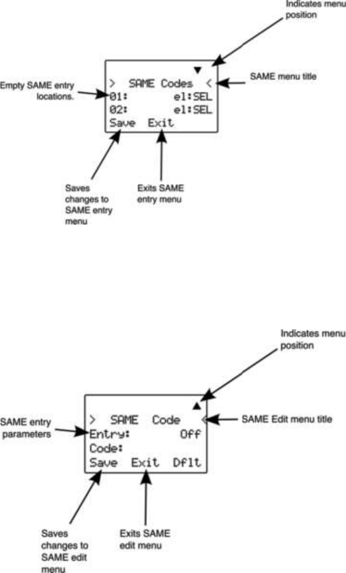
Use the # or $ keys on the 5-way pushbutton pad to scroll to
the desired SAME code entry.
Press the SEL key on the 5-way pushbutton pad to edit the
selected SAME entry. The scanner display will appear as follows:
With the Entry: field selected, press " on the 5-way
pushbutton pad to turn the entry on.
0715 User Manual Page 59

Scroll to the Code: field and press " on the 5-way pushbutton
pad to enter a SAME location code. Use the keypad to enter a
SAME code.
NOTE: The 0715 supports entry of Extended SAME codes, which can
include numbers and letters. The text entry mode is used to enter
both numerical SAME codes and extended SAME codes. To enter a
numerical SAME code, simply precede each number in the SAME
code with “1”. For example, to enter SAME code 048113, press 10
14 18 11 11 13.
Scroll to the Event: field. Note the current default of ***, which
will allow all messages for the specified SAME location code. We
recommend that you leave the event code with “***” to receive
all alerts.
Scroll to the Tag: field. We suggest that you enter a tag name
here that corresponds with the SAME location code that you
have entered. Press " on the 5-way pushbutton pad to edit the
tag name, and use the standard text entry method to enter your
tag. Using our Dallas County example, you would enter the
following:
31 D
21 A
53 L
53 L
21 A
74 S
. <space>
23 C
63 O
82 U
62 N
81 T
93 Y
Scroll to the Alarm: field. Note that you can specify different
alarm sounds for this SAME entry. We recommend that you use
the default setting here for general purpose weather alerting.
Scroll to the Lockout: field. Note that Lockout is currently set to
off. Lockout is a special purpose parameter that can be used to
lock out individual event or area codes. We recommend that you
leave Lockout set to off for general purpose weather alerting.
0715 User Manual"Page 60
When you have finished editing your SAME entry, press the
Save softkey to store the data, then press the Save softkey to
save all SAME changes and return to the Weather mode.
Activating SAME Standby Mode
After you have entered your desired SAME codes, you can
activate the SAME Standby Mode to begin standby operation.
The radio will remain silent until a SAME transmission is received
with a code that matches one that you have stored. When a
matching SAME message is received, your radio will sound a
siren alarm, then will play the audio message that follows the
Warning Alert Tone (WAT).
To activate SAME standby mode, press the WX key, use the #
or $ keys to find the best weather radio transmitter for your
location, then press the stby softkey. The softkey will change to
STBY to indicate that SAME Standby Mode is active, and the
scanner will alert when a matching SAME message is received.
Press the STBY softkey again to exit SAME Standby Mode, or
press MAN, SCAN or PGM.
Using V-Scanner Storage
Your 0715 features two types of memory storage. Main memory
is used to store your programming that is used for everyday
monitoring and scanning. V-Scanner memory is used to store
complete copies of your scanner!s main memory for later recall,
including objects, global settings and dedicated search
configurations. We call this feature V-Scanner, for “Virtual
Scanner”. Your 0715 features 21 V-Scanner storage locations,
each capable of storing a copy of your scanner!s main memory.
Having 21 Virtual Scanners is like having 21 scanners in one.
You can custom tailor a main memory configuration to suit your
needs for the type of scanning you do in different situations, then
store that configuration for later use. If you travel frequently, you
may want to create V-Scanners for the areas where you travel.
V-Scanners are also useful for backing up your configurations.
Once you have main memory configured the way you like it, you
can save it to a V-Scanner where it will remain untouched until
you delete, overwrite or recall it. Then, if you happen to make a
mistake while using your main memory that you cannot fix, you
can recall the backup data and start again.
0715 User Manual"Page 61
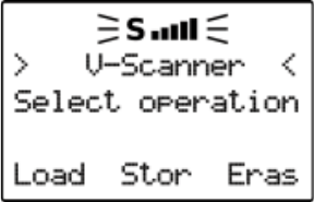
V-Scanners provide a capability that is similar to having a
computer with scanner programming software available all of the
time. Instead of connecting the computer and transferring
configuration files to and from main memory, you use V-
Scanners to save or load main memory configurations in the
field. Each V-Scanner storage location is called a V-Scanner
folder. To begin V-Scanner operations, press FUNC PGM. The
scanner display will appear as follows:
Saving Main Memory To A V-Scanner Folder
To save the current contents of your scanner!s main memory to a
V-Scanner folder, press FUNC, then PGM to enter V-Scanner
mode, then press the Stor softkey. Use the #$ keys on the 5-
way pushbutton pad to scroll to the desired V-Scanner folder,
then press the Stor softkey.
If the selected V-Scanner folder already contains data, you will
be asked if you wish to overwrite the existing data with new data
from your current version of main memory. Press the YES softkey
to proceed, or the NO softkey to cancel. If you decide the
overwrite existing data, or if the selected V-Scanner folder is
already empty, the scanner will prompt you to enter a name for
the stored V-Scanner. The scanner uses the text from Line 4 of
the Welcome Screen as a default name if the folder is empty, or
the current name if the folder contains data. You can provide
your own text here without overwriting the Line 4 Welcome
Screen text. Use the standard text entry method to type the
name you wish to use, then press the OK softkey. The scanner
will write the contents of main memory to the V-Scanner folder.
This will take approximately four seconds to complete.
Loading A Stored V-Scanner Folder To Main Memory
To load the contents of a previously saved V-Scanner folder into
your scanner!s main memory, press FUNC, then PGM to enter V-
Scanner mode, then press the Load softkey. Use the #$ keys
0715 User Manual Page 62

on the 5-way pushbutton pad to scroll to the desired V-Scanner
folder, then press the Load softkey. The scanner will ask you to
confirm that you wish to overwrite the current contents of main
memory. Press the YES softkey to proceed, or the NO softkey to
abort. The data transfer takes approximately 4 seconds to
complete.
Erasing V-Scanner Folders
You can erase V-Scanner folders when you no longer need them
and wish to make the folder storage location available for other
data.
To erase the contents of a previously saved V-Scanner folder,
press FUNC, then PGM to enter V-Scanner mode, then press the
Eras softkey. Use the #$ keys on the 5-way pushbutton pad to
scroll to the desired V-Scanner folder, then press the Eras
softkey. The scanner will ask you to confirm that you wish to
overwrite the current contents of the selected V-Scanner folder.
memory. Press the YES softkey to proceed, or the NO softkey to
abort.
Standard Text Entry Method and QuickText
Your 0715 features a high-contrast, backlit alphanumeric display
that provides constant feedback about what the radio is doing
while scanning and monitoring your “scannable objects”. To get
the most out of your scanner and this display, you will want to
name your objects as you program them into the radio. This
allows for easy identification of active objects while the radio is
scanning, and makes it easier than ever to find objects that you
wish to monitor, edit or delete using the powerful FIND feature.
Your scanner uses a simple text entry method that allows entry of
all uppercase and lowercase letters of the alphabet, numbers,
and punctuation symbols. Your scanner also features GRE!s
exclusive QuickText feature, which allows you to store up to 10
commonly used text items for instant recall while editing
alphanumeric fields.
Entering and Editing Alphanumeric Information
A Standard Text Entry Method is used for entering alphanumeric
information into the radio. This method allows easy access to
each letter in the alphabet by pressing two keys that represent
the letter.
Take a moment to study the numeric keys on the keypad and you
will notice that keys 2-9 each have three or four letters silk
0715 User Manual"Page 63
screened on the front panel just above each key. To enter a letter
in an alphanumeric text field, simply press the the number key
below the letter you wish to type first, then press the number key
that corresponds with the position of the letter in the silk screen
group. For example, the number 2 is used to access the letters
A, B and C. To type the letter A, press 2 to select the ABC group,
then 1 to select the first letter in the group, A. Likewise, to type
the letter B, press 2 to select the ABC group, then press 2 again
to select the second letter in the group. And, to type the letter C,
simply press 2, then 3 to select the third letter in the “ABC”
group.
To enter numbers in alphanumeric text fields, press 1 first, then
the number you wish to type.
To enter punctuation, press 0 first to see the first set of
punctuation, then press the number key that corresponds with
the position of the desired punctuation mark in the set.
Press the . (period) key to enter a SPACE.
While using Standard Text Entry, the FUNC key serves as a shift
key. For letters, uppercase text is typed by default, and you can
shift to lowercase by pressing the FUNC key while entering text.
For punctuation, the FUNC key accesses a second set of
punctuation marks.
The 0715 character set and corresponding entry codes are
provided below for reference.
0715 User Manual"Page 64

Char
Code
Char
Code
Char
Code
Char
Code
A 21 O 63 3 13 ? 07
B 22 P 71 4 14 !08
C 23 Q 72 5 15 "09
D 31 R 73 6 16 "00
E 32 S 74 7 17 . 0F1
F 33 T 81 8 18 - 0F2
G 41 U 82 9 19 # 0F3
H 42 V 83 0 10 _ 0F4
I 43 W 91 $ 01 @ 0F5
J 51 X 92 % 02 + 0F6
K 52 Y 93 ! 03 * 0F7
L 53 Z 94 ^ 04 & 0F8
M 61 1 11 ( 05 / 0F9
N 62 2 12 ) 06 , 0F0
Using QuickText
QuickText allows you to store up to 10 commonly used text items
for instant recall while editing alphanumeric fields. For example,
as you search for, store and name new CONV or TGRP objects,
you may find that you type the same words over and over, such
as POLICE, FIRE, SHERIFF, STATE, CITY, COUNTY, etc.
A few common QuickText words are provided for your
convenience. You can keep these, edit them to your preferences,
or replace them with your own custom QuickText words.
QuickText can be used while editing any alphanumeric text field.
To insert a stored QuickText item, while editing an alphanumeric
text field use the !" keys to position the cursor where you what
the QuickText inserted, then press the QTXT softkey. The top
row of the display will show the available QuickText phrases. Use
the #$ keys to scroll through the stored QuickText phrases, and
press SEL to insert the QuickText phrase at the cursor location.
As a shortcut, you may press the number key on the numeric
keypad that corresponds with the QuickText item you wish to
use, instead of scrolling and pressing SEL.
0715 User Manual"Page 65

Customizing QuickText
To edit the QuickText words, press PGM, then the GLOB softkey.
Scroll down to the QTXT section using the $ key on the 5-way
pushbutton pad and find the QTXT storage location that you wish
to change. Press the " key to edit the QTXT entry. Use the
standard text entry method to enter your desired text. When you
use your QTXT entry in a text field, any unused spaces will be
filled with space characters. If you want to leave room for
additional text after the QTXT is loaded into a text field, include a
space after your text, then a dollar sign ($). This will place one
space after your QTXT when you use your QTXT in a text field,
and the edit cursor will be positioned just after that space where
you can continue appending text in the text field before you save
it. For example, if you use the entry SHERIFF in the QTXT
storage location, your text entry field will look like this after you
load the QTXT “SHERIFF”:
SHERIFF !"note that cursor is positioned at end of text field
if you use the entry SHERIFF $ in the QTXT storage location,
your text entry field will look like this after you load the QTXT
“SHERIFF”:
SHERIFF !"note that cursor is positioned at end of the word
Once you are finished editing your QTXT storage location, press
the SAVE softkey to save the QTXT, then press the SAVE softkey
again to save the changes you made to the GLOB menu.
Detailed Menu Reference
Your 0715 scanner uses GRE!s exclusive Object Oriented User
Interface, which features a powerful menu system that is used to
configure the various scannable objects that your scanner is
capable of receiving. The 0715 design also includes a Global
Settings (GLOB) menu that provides unprecedented control over
the radio wide settings used throughout your scanner. This
section of the manual provides detailed information all of the
menus and menu parameters.
Each menu parameter features a Dflt softkey that can be used
to restore that can be used to restore the value to the factory
defaults. This can be very useful if you make a change to a
parameter but do not like the result.
0715 User Manual"Page 66

HINT: Remember that context sensitive help is available for every menu
parameter. Press FUNC SEL to view help for the selected
parameter. Press SEL to exit help.
HINT: It"s easy to fix things if you inadvertently change a parameter and
then can"t remember how to make it right again. Each parameter
includes a Dflt softkey, which, when pressed, restores the factory
default setting for that parameter.
0715 User Manual"Page 67

GLOB Menu Reference
The GLOB menu stores all of the radio-wide settings used by the
scanner. The GLOB menu allows you to “tweak” these settings to
your liking. The default settings will work fine for most users, but
most users will want to use the GLOB menu to personalize the
radio to suit their individual tastes. The active parameter is
always the middle parameter and is indicated by a flashing “:”.
The entire GLOB menu is shown below. Note that some GLOB
parameter changes do not take effect until the GLOB menu is
saved.
HINT: You can restore all GLOB settings to their defaults without affecting
your programmed objects or V-Scanners. Power cycle the radio, then
press 0, then 2 during the welcome message display. Press ENT to
confirm the GLOB parameter reset.
GLOB
Parameter
Options
Description
ATTEN Global or
Normal
The attenuator reduces the amount of signal at
the receiver input. This helps reduce interference
from strong nearby transmitters. Global
attenuator mode applies attenuation radio-wide,
regardless of individual object settings. In Normal
attenuator mode, the attenuator follows the
individual object attenuator setting.
Global ATTEN On or off
When the ATTEN mode is set to Global, this
controls whether the Global attenuator is on or
off.
BATTERY
NiMH,
Alkaline or
NiCad
Loads low battery profile for each different
battery type.
SOUND MODE Key or
Stlth
Controls the key beeps. Selecting Key will
provide a short beep with each keypress.
Selecting Stlth (Stealth) will mute the key beep
sounds.
ALERT MODE
Both, Tone,
Light, Off
Controls the ALERT LED and Audible Alarm
behavior. Both allows the LED and Tone. Tone
allows the audible alarm only. Light allows the
LED only. Off deactivates the ALERT LED and
Audible Alarm feature.
0715 User Manual"Page 68

GLOB
Parameter
Options
Description
LIGHT MODE
Norml,
Key, Ignre,
On, Stlth
Controls the backlight operation. Norml (Normal)
uses the backlight key on the keypad. Key
activates the backlight when any key is pressed.
Ignore activates the backlight when a key is
pressed, and that key!s normal function is
ignored if the backlight is off when it is pressed.
On causes the backlight to remain on all the
time. Stlth (Steath) disables the backlight.
LIGHT SECS 1-99
seconds
Controls the amount of time the backlight
remains on for Normal, Key and Ignore light
modes
LIGHT AREA
Both, LCD,
Keybd
Controls what area is illuminated when the
backlight is on. Both illuminates the LCD and the
keypad, LCD illuminates the display only. Keybd
(Keyboard) illuminates the keypad only.
SCAN LISTS SEL Enters sub menu for scan list settings and status
Dflt
ScanList 1-20
Sets default destination scan lists for CONV Stor
from Searches, Spectrum Sweeper and Tune
EDACS Format AFS or
DEC
Sets EDACS talkgroup ID data entry mode. AFS
uses Agency-Fleet-Subfleet notation. DEC uses
Decimal notation.
SRCH L/Outs SEL
Enters sub menu for review, editing or deletion of
search lockout frequencies
WxPri On or Off Toggles Weather Priority Mode on or of. Also
accessed by pressing WX!PRI
WX Alrm Time 0-600
seconds
Sets amount of time for weather siren to sound
after receiving matching SAME code in SAME
Standby Mode. Use 0 to stop alarm upon receipt
of 1050 Hz WAT.
DIG AGC On or Off
Sets digital AGC mode on or off. Useful to
compensate for low or high digital audio levels
caused at the system.
Supertrack On or Off Alternative DSP decoding algorithm. May help
reception on some systems.
CONTRAST 1-7 Sets LCD contrast. Use !" keys on 5-way
pushbutton pad.
OWNER SEL Enters sub menu to set Welcome Message text
display.
QTXT0-9 Text value Sets QTXT (Quick Text) 0-9 text. Use “$” to
indicate end of text.
0715 User Manual"Page 69

GLOB
Parameter
Options
Description
Color 0-7 RGB value
Sets intensity of red, green and blue LEDs. Press
SEL to edit colors. Use !" keys to scroll to R,
G or B LED settings. Use numeric keys to
activate preset intensity levels for each LED, or
use #$ keys to fine scroll intensity.
Search Delay 1-100 x
100 mS Sets wait for reply delay for all search modes
LCD BlinkOn
1-250 x 10
mS
For alternating text displays, sets the display time
for the primary display element.
LCD BlinkOff
1-250 x 10
mS
For alternating text displays, sets the display time
for the secondary display element.
LED BlinkOn
1-250 x 10
mS
When the ALERT LED setting for an object is set
to Flash, this is the amount of time the LED stays
turned on.
LED BlinkOff
1-250 x 10
mS
When the ALERT LED setting for an object is set
to Flash, this is the amount of time the LED stays
turned off.
Battery Info SEL Displays current battery voltage, DAC value and
charge time remaining if battery is charging.
Charge Time 0-99
Battery charge time in hours. 0=charger off. The
battery charger is timer based and charges at a
current rate of 150 mA. The charger is disabled
when BATTERY is set to Alkaline. A default
charge time of 9 hours is used for NiCAD
batteries, and 16 hours for NiMH batteries.
PC/IF Send SEL
Press SEL to send contents of main memory to a
PC connected to the PC/IF port.
Clone Send SEL Press SEL to send data using clone mode
Clone Recv SEL Press SEL to receive data using clone mode
Clear Hits SEL Press SEL to clear all hit counters.
Clear FAV SEL Press SEL to clear the Favorites scan list.
Memory Info SEL Press SEL to see the current memory usage.
0715 User Manual"Page 70

CONV Menu Reference
The CONV menu is used when creating new Conventional
Channel objects, or editing existing Conventional Channel
objects. All menus are shown in the scanner!s display as a three
line window that can be scrolled up or down to access the
various different parameters. The active parameter is always the
middle parameter and is indicated by a flashing “:”. The entire
CONV menu is shown below:
CONV
Parameter
Options
Description
Freq
Any
supported
frequency
in MHz
The frequency that the CONV object will use.
Tag
Alpha-
numeric
text
The alphanumeric display name for the CONV
channel. Use the standard text entry method or
QTXT to name the object.
Modulation AM, FM,
NFM, AU
Modulation setting for the CONV channel. In
most cases AU will work fine. Use AM to override
and force AM modulation, FM to force FM
modulation, NFM to force narrow FM modulation.
Sq Mode
Search,
None,
CTCSS,
DCS, P25
Sets subaudible squelch mode or Project 25
conventional digital modulation. Use Search to
automatically analyze signals to determine
squelch mode and code. Use None to ignore
subaudible squelch. Use CTCSS for tone coded
squelch, DCS for digital coded squelch, or P25
for Project 25 conventional digital operation.
Used in conjunction with Squelch Code
parameter below.
Squelch Code
CTCSS
Hz, DCS
Code, P25
NAC
Sets CTCSS tone, DCS code, or P25 NAC
depending on Sq Mode setting. Use Search to
detect tone or code value for selected squelch
type.
Scan Lists
On or Off
for Scan
Lists 1-20
Sets membership in Scan Lists. Use !" keys to
scroll through scan lists. Use SEL key to toggle
Scan List membership.
Delay On or Off
Controls whether a Delay is used to wait for reply
traffic after a transmission on the CONV channel.
Delay Time 1-200
Sets the amount of time (in 100 millisecond
intervals) for the wait for reply delay if Delay is
On, e.g., 20=2 seconds.
0715 User Manual"Page 71

CONV
Parameter
Options
Description
L/Out On or Off
Permanent lockout for the CONV channel. Also
accessed by pressing FUNC L/OUT while the
scanner is stopped on the CONV object.
Priority On or Off Turns Priority Mode on or off for the CONV
object.
Atten On or Off
When on, applies 20 dB of attenuation to all
transmissions on the CONV channel. Useful in
areas where interference from nearby strong
signals is present.
LED Flash Solid or
Flash
Controls whether the ALERT LED flashes or
remains on solid when the ALERT LED is used.
LED Color 0-7
Sets LED color to 0-7 as defined in the GLOB
menu. By default, 0=LED Off, 1=Red, 2=Yellow,
3=Green, 4=Cyan, 5=Blue, 6=Magenta, 7=White.
Latch LED On or Off
Normally the ALERT LED is active only while the
object is receiving a transmission. When Latch is
on, the ALERT LED will remain lit after the
transmission is complete, unless overridden by a
subsequent object that is also using the ALERT
LED.
Backlight
On, Off or
Flash
Controls whether the backlight should be on, off
or flashing while the object is active.
Alarm
None,
Chirp, Hi-
Lo, Alert,
Ring, 2-
Chirp, Fast
Hi-Lo,
DTMF#
Sets the Audible Alarm for the CONV object.
When an Audible Alarm is selected, the selected
alarm will play at the beginning of each
transmission on the CONV object, or anytime the
scanner stops for activity on the CONV object
while scanning.
Fav On or Off When On, the CONV object is a member of the
Favorites scan list.
Skywarn On or Off When On, the CONV object is a member of the
Skywarn scan list.
Hit Count Numeric
value
Increments each time a transmission is received
on the CONV object. Press the Dflt softkey to
reset to 0.
0715 User Manual"Page 72

TGRP Menu Reference
The TGRP menu is used when creating new Trunking Talkgroup
objects, or editing existing Trunking Talkgroup objects. All menus
are shown in the scanner!s display as a three line window that
can be scrolled up or down to access the various different
parameters. The active parameter is always the middle
parameter and is indicated by a flashing “:”. The entire TGRP
menu is shown below:
TGRP
Parameter
Options
Description
TSYS
New or
previously
stored
trunking
system
object
(TSYS)
To enter a new trunking system, use the !"
keys to scroll through the stored systems until
NEW appears, then press SEL to enter the
parameters for the new TSYS. To use a trunking
system that you have previously entered, use the
!" keys to scroll to the desired system.
ID
Decimal,
hex or AFS
depending
on TSYS
type
The digital address of the talkgroup or individual
radio ID on the trunked radio system.
Type Group or
Private
Use Group for talkgroup ID, Private for individual
radio ID.
Tag
Alpha-
numeric
text
The alphanumeric display name for the TGRP.
Use the standard text entry method or QTXT to
name the object.
Scan Lists
On or Off
for Scan
Lists 1-20
Sets membership in Scan Lists. Use !" keys to
scroll through scan lists. Use SEL key to toggle
Scan List membership.
Delay On or Off
Controls whether a Delay is used to wait for reply
traffic after a transmission on the TGRP.
Delay Time 1-200 x
100 mS
Sets the amount of time (in 100 millisecond
intervals) for the wait for reply delay if Delay is
On, e.g., 20=2 seconds.
L/Out On or Off
Permanent lockout for the TGRP. Also accessed
by pressing FUNC L/OUT while the scanner is
stopped on the TGRP object.
Priority On or Off Turns Priority Mode on or off for the TGRP
object.
LED Flash Solid or
Flash
Controls whether the ALERT LED flashes or
remains on solid when the ALERT LED is used.
0715 User Manual"Page 73

TGRP
Parameter
Options
Description
LED Color 0-7
Sets LED color to 0-7 as defined in the GLOB
menu. By default, 0=LED Off, 1=Red, 2=Yellow,
3=Green, 4=Cyan, 5=Blue, 6=Magenta, 7=White.
Latch LED On or Off
Normally the ALERT LED is active only while the
object is receiving a transmission. When Latch is
on, the ALERT LED will remain lit after the
transmission is complete, unless overridden by a
subsequent object that is also using the ALERT
LED.
Backlight
On, Off or
Flash
Controls whether the backlight should be on, off
or flashing while the object is active.
Alarm
None,
Chirp, Hi-
Lo, Alert,
Ring, 2-
Chirp, Fast
Hi-Lo,
DTMF#
Sets the Audible Alarm for the TGRP object.
When an Audible Alarm is selected, the selected
alarm will play at the beginning of each
transmission on the TGRP object, or anytime the
scanner stops for activity on the TGRP object
while scanning.
Fav On or Off When On, the TGRP object is a member of the
Favorites scan list.
Hit Count Numeric
value
Increments each time a transmission is received
on the TGRP object. Press the Dflt softkey to
reset to 0.
0715 User Manual"Page 74

TSYS Menu Reference
The TSYS menu is used when creating new Trunking System
objects, or editing existing Trunking System objects. All menus
are shown in the scanner!s display as a three line window that
can be scrolled up or down to access the various different
parameters. The active parameter is always the middle
parameter and is indicated by a flashing “:”. The entire TSYS
menu is shown below:
TSYS Parameter
Options
Description
Type
MOT
800/900,
MOT VHF/
UHF, P25
7/8/900,
P25 AUTO,
EDACS
STD,
EDACS
NAROW,
LTR
Sets the trunking system type. Choose
MOT800/900 if the system is a Motorola 800 or
900 MHz analog or digital trunked radio system
that uses the 3600 baud control channel. Use
P25 7/8/900 if the system is a Project 25 trunked
radio system operating on 700, 800 or 900 MHz
frequencies. Use P25 AUTO if the system is a
Project 25 trunked radio system operating on
VHF or UHF frequencies. Use EDACS STD for
most 800 MHz EDACS systems using the 9600
BPS EDACS control channel. Use EDACS
NAROW for most 900 MHz and some VHF/UHF
EDACS systems using the 4800 BPS EDACS
control channel. Use LTR for Logic Trunked
Radio (LTR) systems.
Tag
Alpha-
numeric
text
The alphanumeric display name for the TSYS.
Use the standard text entry method or QTXT to
name the object.
Frequencies SEL
Press SEL to enter trunked radio system
frequencies. Enter control channel frequencies in
any order for all Motorola and Project 25 trunking
systems. Enter system frequencies in LCN order
for all EDACS trunking systems. Enter system
frequencies in Home Repeater order for LTR
systems.
Dwell 0-200 x
100 mS
Sets the amount of time the scanner dwells on a
Motorola, P25 or EDACS system control channel
for activity on programmed talkgroups. Use 0 for
automatic mode, which uses control channel
information to determine when all current
talkgroup information has been broadcast by the
system.
Narrow FM Yes or No
Use Yes when the system is known to use
Narrow FM modulation. Most 900 MHz analog
trunked radio systems utilize NFM modulation.
This setting has no effect on digital trunked radio
system performance.
0715 User Manual"Page 75

TSYS Parameter
Options
Description
Atten On or Off
When on, applies 20 dB of attenuation to all
transmissions on this TSYS. Useful in areas
where interference from nearby strong signals is
present.
L/Out On or Off
Permanent lockout for the TSYS. When On, no
traffic will be received on any programmed
TGRPs for this TSYS.
Multi-Site On or Off
When On, performance is optimized for multi-site
networked trunked radio systems. The radio will
use the Threshold Hi and Threshold Lo
parameters to automatically select the best
networked site for your location. Used with
Motorola and P25 multi-site networked systems.
Threshold Hi 1-99
Available When Multi-Site is set to On. Sets the
control channel decode % threshold for a site to
be considered good when looking for a new site.
Threshold Lo 1-99
Available When Multi-Site is set to On. Sets the
control channel decode % threshold for a site to
be considered out of range, which will begin the
process of looking for a new site.
T Tables
Normal,
Splinter,
Custom
For Motorola and P25 systems only - sets
custom channel tables. Use !",to select option,
press SEL on Custom to enter custom table
information
Fleet Map SEL For Motorola Type I systems only - sets fleet map
0715 User Manual"Page 76

LMIT Menu Reference
The LMIT menu is used when creating new Limit Search objects,
or editing existing Limit Search objects. All menus are shown in
the scanner!s display as a three line window that can be scrolled
up or down to access the various different parameters. The
active parameter is always the middle parameter and is indicated
by a flashing “:”. The entire LMIT menu is shown below:
LMIT Parameter
Options
Description
FrLO
Any
supported
frequency
in MHz
A frequency that will be used as the lower limit
for the limit search range
FrHi
Any
supported
frequency
in MHz
A frequency that will be used as the upper limit
for the limit search range
Tag
Alpha-
numeric
text
The alphanumeric display name for the LMIT
search. Use the standard text entry method or
QTXT to name the object.
Modulation AM, FM,
NFM, AU
Modulation setting for the LMIT search. In most
cases AU will work fine. Use AM to override and
force AM modulation, FM to force FM
modulation, NFM to force narrow FM modulation.
Scan Lists
On or Off
for Scan
Lists 1-20
Sets membership in Scan Lists. Use !" keys to
scroll through scan lists. Use SEL key to toggle
Scan List membership.
Delay On or Off
Controls whether a Delay is used to wait for reply
traffic after a transmission is received during the
LMIT search.
Delay Time 1-200
Sets the amount of time (in 100 millisecond
intervals) for the wait for reply delay if Delay is
On, e.g., 20=2 seconds.
L/Out On or Off
Permanent lockout for the LMIT channel. Also
accessed by pressing FUNC L/OUT while the
scanner is stopped on the LMIT object.
Zeromatic On or Off
When on, enhances the scanner!s ability to lock
on to the actual center frequency of a search hit
instead of an adjacent frequency.
Atten On or Off
When on, applies 20 dB of attenuation to all hits
received on the LMIT search. Useful in areas
where interference from nearby strong signals is
present.
0715 User Manual"Page 77

LMIT Parameter
Options
Description
Search Dir #$ Sets search direction used when LMIT object is
active.
LED Flash Solid or
Flash
Controls whether the ALERT LED flashes or
remains on solid when the ALERT LED is used.
LED Color 0-7
Sets LED color to 0-7 as defined in the GLOB
menu. By default, 0=LED Off, 1=Red, 2=Yellow,
3=Green, 4=Cyan, 5=Blue, 6=Magenta, 7=White.
Latch LED On or Off
Normally the ALERT LED is active only while the
object is receiving a transmission. When Latch is
on, the ALERT LED will remain lit after the
transmission is complete, unless overridden by a
subsequent object that is also using the ALERT
LED.
Backlight
On, Off or
Flash
Controls whether the backlight should be on, off
or flashing while the object is active.
Alarm
None,
Chirp, Hi-
Lo, Alert,
Ring, 2-
Chirp, Fast
Hi-Lo,
DTMF#
Sets the Audible Alarm for the LMIT object. When
an Audible Alarm is selected, the selected alarm
will play anytime the scanner stops for activity on
the LMIT object while scanning.
Fav On or Off When On, the LMIT object is a member of the
Favorites scan list.
Hit Count Numeric
value
Increments each time a transmission is received
on the LMIT object. Press the Dflt softkey to
reset to 0.
0715 User Manual"Page 78

SRVC Menu Reference
The SRVC menu is used when creating new Service Search
objects, or editing existing Service Search objects. All menus are
shown in the scanner!s display as a three line window that can
be scrolled up or down to access the various different
parameters. The active parameter is always the middle
parameter and is indicated by a flashing “:”. The entire SRVC
menu is shown below:
SRVC
Parameter
Options
Description
Srvc
Pub Safety,
Aircraft,
Amateur,
CB,
Marine,
FRS/GM/
MURS,
Railroad
Public Safety (Pub Safety) - Searches commonly
used public safety frequencies. Groups are as
follows:
"0: 33.4-46.5 MHz
"1: 151-170 MHz
"2: 453-467 MHz
"3: 764-806 MHz
"4: 851-869 MHz
Aircraft - Searches civilian and military air
frequencies. Groups are as follows:
"0: 108-118 MHz
"1: 118-137 MHz
"2: 138-150 MHz
"3: 225-400 MHz
Amateur - Searches amateur radio frequencies.
Groups are as follows:
"0: 28.0-29.7 MHz
"1: 50-54 MHz
"2: 144-148 MHz
"3: 222-225 MHz
"4: 420-450 MHz
"5: 902-928 MHz
"6: 1240-1300 MHz
CB - Searches the citizen!s band radio
frequencies
Marine - Searches the VHF-FM marine radio
band
FRS/GMRS/MURS/DOT/STAR (F/G/MURS) -
Searches the FRS, GMRS, MURS, DOT and
STAR radio frequencies
Railroad - searches the Association of American
Railroads (AAR) VHF railroad frequencies used
in the US and Canada
0715 User Manual"Page 79

SRVC
Parameter
Options
Description
Groups
!" to
scroll, SEL
to toggle
on/off
Toggle search groups when Pub Safety, Aircraft
and Amateur service searches are used.
Tag
Alpha-
numeric
text
The alphanumeric display name for the SRVC
search. Use the standard text entry method or
QTXT to name the object.
Modulation AM, FM,
NFM, AU
Modulation setting for the SRVC search. In most
cases AU will work fine. Use AM to override and
force AM modulation, FM to force FM
modulation, NFM to force narrow FM modulation.
Scan Lists
On or Off
for Scan
Lists 1-20
Sets membership in Scan Lists. Use !" keys to
scroll through scan lists. Use SEL key to toggle
Scan List membership.
Delay On or Off
Controls whether a Delay is used to wait for reply
traffic after a transmission on the SRVC search.
Delay Time 1-200
Sets the amount of time (in 100 millisecond
intervals) for the wait for reply delay if Delay is
On, e.g., 20=2 seconds.
L/Out On or Off
Permanent lockout for the SRVC object. Also
accessed by pressing FUNC L/OUT while the
scanner is stopped on the SRVC object.
Zeromatic On or Off
When on, enhances the scanner!s ability to lock
on to the actual center frequency of a search hit
instead of an adjacent frequency.
Atten On or Off
When on, applies 20 dB of attenuation to all hits
received on the SRVC search. Useful in areas
where interference from nearby strong signals is
present.
Search Dir #$
Sets search direction used when SRVC object is
active.
LED Flash Solid or
Flash
Controls whether the ALERT LED flashes or
remains on solid when the ALERT LED is used.
LED Color 0-7
Sets LED color to 0-7 as defined in the GLOB
menu. By default, 0=LED Off, 1=Red, 2=Yellow,
3=Green, 4=Cyan, 5=Blue, 6=Magenta, 7=White.
Latch LED On or Off
Normally the ALERT LED is active only while the
object is receiving a transmission. When Latch is
on, the ALERT LED will remain lit after the
transmission is complete, unless overridden by a
subsequent object that is also using the ALERT
LED.
0715 User Manual"Page 80

SRVC
Parameter
Options
Description
Backlight
On, Off or
Flash
Controls whether the backlight should be on, off
or flashing while the object is active.
Alarm
None,
Chirp, Hi-
Lo, Alert,
Ring, 2-
Chirp, Fast
Hi-Lo,
DTMF#
Sets the Audible Alarm for the SRVC object.
When an Audible Alarm is selected, the selected
alarm will play anytime the scanner stops for
activity on the SRVC object while scanning.
Fav On or Off When On, the SRVC object is a member of the
Favorites scan list.
Hit Count Numeric
value
Increments each time a transmission is received
on the SRVC object. Press the Dflt softkey to
reset to 0.
0715 User Manual"Page 81

SWPR Menu Reference
The SWPR menu is used when creating new Spectrum Sweeper
objects, or editing existing Spectrum Sweeper objects. All menus
are shown in the scanner!s display as a three line window that
can be scrolled up or down to access the various different
parameters. The active parameter is always the middle
parameter and is indicated by a flashing “:”. The entire SWPR
menu is shown below:
SWPR
Parameter
Options
Description
Tag
Alpha-
numeric
text
The alphanumeric display name for the SWPR
search. Use the standard text entry method or
QTXT to name the object.
Type
All Bands
or Pub
Safety
Use !" to select All Bands or Public Safety. All
Bands covers the entire frequency range of the
scanner. Public Safety covers frequency ranges
commonly used for public safety
communications.
Sub-bands !", SEL
Sub bands are available when using SWPR in All
Bands or Public Safety mode. In All Bands, the
sub bands are defined as follows:
"0: 25-54 MHz
"1: 108-137 MHz
"2: 137-174 MHz
"3: 216-300 MHz
"4: 300-406 MHz
"5: 406-470 MHz
"6: 470-512 MHz
"7: 806-869 MHz
"8: 896-960 MHz
"9: 1240-1300 MHz
In Public Safety, the sub bands are defined as
follows:
"0: 33.4-46.5 MHz
"1: 151-170 MHz
"2: 453-467 MHz
"3: 764-806 MHz
"4: 851-869 MHz"
Scan Lists
On or Off
for Scan
Lists 1-20
Sets membership in Scan Lists. Use !" keys to
scroll through scan lists. Use SEL key to toggle
Scan List membership.
Delay On or Off
Controls whether a Delay is used to wait for reply
traffic after a transmission on the SWPR search.
0715 User Manual"Page 82

SWPR
Parameter
Options
Description
Delay Time 1-200
Sets the amount of time (in 100 millisecond
intervals) for the wait for reply delay if Delay is
On, e.g., 20=2 seconds.
L/Out On or Off
Permanent lockout for the SWPR search. Also
accessed by pressing FUNC L/OUT while the
scanner is stopped on the SWPR object.
Zeromatic On or Off
When on, enhances the scanner!s ability to lock
on to the actual center frequency of a search hit
instead of an adjacent frequency.
Atten On or Off
When on, applies 20 dB of attenuation to all hits
received on the SWPR search. Useful in areas
where interference from nearby strong signals is
present.
Special On or Off
SWPR works by quickly sweeping the RF
spectrum in 1 MHz increments to find nearby
strong signals. If the 1 MHz sweep indicates that
activity is present in the 1 MHz range, SWPR
sweeps that range to find the source.
Special Spectrum Sweeper mode helps improve
Spectrum Sweeper speed in locations where
numerous strong RF sources are present and in
close proximity to each other spectrally. An
example would be an area where there are many
VHF paging transmitters nearby operating in the
152 MHz range. When Special mode is on,
SWPR will skip any 1 MHz segment where 5 or
more hits have been locked out using the FrL/O
key.
Search Dir #$
Sets search direction used when SWPR object is
active.
LED Flash Solid or
Flash
Controls whether the ALERT LED flashes or
remains on solid when the ALERT LED is used.
LED Color 0-7
Sets LED color to 0-7 as defined in the GLOB
menu. By default, 0=LED Off, 1=Red, 2=Yellow,
3=Green, 4=Cyan, 5=Blue, 6=Magenta, 7=White.
Latch LED On or Off
Normally the ALERT LED is active only while the
object is receiving a transmission. When Latch is
on, the ALERT LED will remain lit after the
transmission is complete, unless overridden by a
subsequent object that is also using the ALERT
LED.
Backlight
On, Off or
Flash
Controls whether the backlight should be on, off
or flashing while the object is active.
0715 User Manual"Page 83

SWPR
Parameter
Options
Description
Alarm
None,
Chirp, Hi-
Lo, Alert,
Ring, 2-
Chirp, Fast
Hi-Lo,
DTMF#
Sets the Audible Alarm for the SWPR object.
When an Audible Alarm is selected, the selected
alarm will play anytime the scanner stops for
activity on the SWPR object while scanning.
Fav On or Off When On, the SWPR object is a member of the
Favorites scan list.
Hit Count Numeric
value
Increments each time a transmission is received
on the SWPR object. Press the Dflt softkey to
reset to 0.
0715 User Manual"Page 84

Index
...........................................................About this manual"8
..........................................................Accessories, 0715"15
.....................ALERT LED with audible alarm examples"47
...........Alphanumeric information, how to enter and edit"63
..........................................................................Antenna"20
.........................Audible alarm and ALERT LED settings"47
..............................Audible alarms and the ALERT LED"47
.........................................................Batteries, installing"19
................................................................CONV defined"10
...................................................CONV menu reference"71
..................Conventional channel essential parameters"21
...........................Conventional Channel Object (CONV)"21
.....................Dedicated Limit and Search modes, using"51
..............................................................Deleting objects"45
.........................................Display Icons, understanding"16
..................DUPE, how to use to speed up object entry"28
..................................................FCC rules for scanning"10
.........................................................................Features"2
....................................................Finding stored objects"41
.................................Finding stored objects using filters"42
.................................Finding stored objects using FIND"41
...............................................Five way pushbutton pad"17
....................................Frequency, mode and step table"91
.............................................................Front view. 0715"13
....................................Getting Familiar With Your 0715"13
...............................................................Getting Started"19
.................................................GLOB menu Reference"68
.....................................................................Introduction"1
..................................................Keypad, understanding"17
.................................Limit Search essential parameters"32
............................................Limit Search Object (LMIT)"32
..................................................................LMIT defined"10
.....................................................LMIT menu reference"77
...................................................LMIT, dedicated mode "51
.......................................................Lockout, permanent"43
..............................................................Lockout, search"44
..........................................................Lockout, talkgroup"44
........................................................Lockout, temporary"42
..............................................................Menu reference"66
.............................................................Numeric keypad"17
...................Object abbreviations used in this document"8
................................................................Object lockout"42
...............................................Object Numbering, about"31
.................................Object Oriented Scanning, what is"7
0715 User Manual"Page 85
..................Object Oriented User Interface, background"4
......................Object Oriented User Interface, overview"4
.........................Objects, creating your first new objects"20
...............................................................Operation keys"17
...................................................................Powering on"20
....................................................................Priority scan"46
........................................Priority, CONV characteristics"46
........................................Priority, TGRP characteristics"46
.............................Priority, turning on and off for objects"46
........................Priority, turning Priority mode on and off"46
..........................................................QTXT (QuickText)"65
..........................................Quicktext, how to customize"66
.............................................................Rear view, 0715"14
................................................Remote Control Protocol"88
.................................Remote control protocol, Get LCD"89
..............................Remote control protocol, Get Status"88
...............................Remote control protocol, Send Key"89
....................................................SAME entry examples"57
.....................SAME location and event codes, entering"58
.....................................................SAME standby mode"55
....................................SAME standby mode, activating"61
.............................Scan list organization, by application"39
.............................Scan list organization, by object type"39
.....................Scan list organization, by trunking system"39
............................Scan list organization, geographically"38
.................................Scan Lists, enabling and disabling"40
........................................Scan lists, grouping objects in"38
......................................Scan Lists, mapping objects to"39
............................................................Scanning Legally"11
..............................................Scanning, basic operation"28
..............................................Search modes, dedicated"48
........................................................Search object types"32
............................Service Search essential parameters"35
........................................Service search object (SRVC)"35
.........................................................................Softkeys"17
............................................Specifications (preliminary)"92
......................Spectrum Sweeper essential parameters"34
...............................Spectrum Sweeper Object (SWPR)"34
................................................................SRVC defined"10
...................................................SRVC menu reference"79
.................................................SRVC, dedicated mode"51
............................................Standard text entry method"63
................................................Startup topics, advanced"31
.......................................................Startup topics, other"41
............................................................Startup, first time"19
................................................................SWPR defined"10
0715 User Manual"Page 86
.................................................SWPR Menu Reference"82
.................................................SWPR, dedicated mode"48
...............................................Talkgroup Object (TGRP)"24
................................................................TGRP defined"9
...................................................TGRP menu reference"73
......................Trunking Talkgroup essential parameters"24
.................................................................TSYS defined"9
....................................................TSYS menu reference"75
.................................TSYS object, setting up and using"24
..................................................TUNE, dedicated mode"50
......................................................................Unpacking"19
...............................................V-Scanner storage, using"61
.............................................V-Scanner, erasing folders"63
......V-Scanner, loading a stored folder to main memory"62
...................V-Scanner, saving main memory to a folder"62
...................................................Weather modes, using"54
....................................................Weather priority mode"55
.......................................................Weather radio mode"54
0715 User Manual"Page 87

Appendix A - Remote Control Protocol Version 0.01
The 0715 includes a simple remote control interface protocol that
is suitable for use with a PC application designed to provide a
remote control and display capability. The ideal PC application
should provide a means by which a user can interact with a
visual representation of the scanner!s keypad and display.
Remote Control Mode is active at all times, and does not require
that the radio be placed in any special remote mode in order for it
to be used.
The basic remote control command/response format is as
follows:
<STX><msgCode><msgData><ETX><sum>
where:
<STX> is an ASCII “Start of Text” symbol (0x02)
<msgCode> is the code that represents the command or
response message type
<msgData> is the data that accompanies a command or a
response
<ETX> is an ASCII “End of Text” symbol (0x03)
<sum> is the sum of all bytes before sum but not including
<STX>, and is sent with every command and response for error
checking.
The following commands are currently supported in RCP Version
0.01:
Get Status
Command:
STX A ETX <sum>
Response:
STX A <mode> <sq> <battL> <battH> <rssiL>
<rssiH> <zmL> <zmH> <ledR> <ledG> <ledB> ETX
<sum>
0715 User Manual"Page 88
NOTE:!<battH> is ORed with 0x80 when on
! ! external power
Get LCD
Command:
STX L ETX <sum>
Response:
STX L <lcd0> <lcd1> ... <lcd63> <icons1>
<icons2> ETX <sum>
NOTE:!<icons1> and <icons2> are bitmapped
! ! representations of display icon status,
! ! as follows:
icons1:
bits 0-2: RSSI bars level, 0-5
bit 3: S icon
bit 4: Batt icon ON
bit 5: Batt icon BLINKING
icons2:
bit 0: 'F' icon
bit 1: 'G' icon
bit 2: 'A' icon
bit 3: 'T' icon
bit 4: up arrow icon
bit 5: down arrow icon
bit 6: LCD backlight status
Send Key
Command:
STX K <keycode> ETX <sum>
Response:
(no response)
Key codes for the Send Key command are as follows:
0715 User Manual"Page 89

Key
Code
Key
Code
Key
Code
Key
Code
SCAN 15 227 PSE 6.24
FUNC 1321 #7CLR 36
MAN 3!14 735 F2 25
WX 17 TEXT 13 829 32
SEL 8ATT 26 923 SRCH 10
FAV 4434 F3 19 L/OUT 5
PRI 11 528 MODE 25 PGM 12
TUNE 16 622 $9ENT 18
133 "2030 F1 31
NOTE: To initiate the “press and hold” action
for the Light key, send code 32 ORed
with 0x80 (value is 0xA0)
0715 User Manual Page 90

Appendix B - Frequency, Step and Mode Specifications
Frequency Range"Step Size"Default Mode
25.0000 - 26.9600 MHz"10 kHz"AM
26.9650 - 27.4050 MHz"10 kHz"AM
27.4100 - 29.5050 MHz"5 kHz"AM
29.5100 - 29.7000 MHz"5 kHz"FM
29.7100 - 49.8300 MHz "10 kHz"FM
49.8350 - 54.0000 MHz"5 kHz"FM
108.000 - 136.9916 MHz "8.33 kHz"AM
137.000 - 137.995 MHz"5 kHz"FM
138.000 - 143.9875 MHz"12.5 kHz"FM
144.000 - 147.9950 MHz"5 kHz"FM
148.000 - 150.7875 MHz"12.5 kHz"FM
150.800 - 150.8450 MHz"5 kHz"FM
150.8525 - 154.4975 MHz"7.5 kHz"FM
154.5150 - 154.6400 MHz"5 kHz"FM
154.6500 - 156.2550 MHz"7.5 kHz"FM
156.2750 - 157.4500 MHz"25 kHz"FM
157.4700 - 161.5725 MHz"7.5 kHz"FM
161.6000 - 161.9750 MHz"5 kHz"FM
162.0000 - 174.0000 MHz "12.5 kHz"FM
216.0025 - 219.9975 MHz"5 kHz"FM
220.0000 - 224.9950 MHz"5 kHz"FM
225.0000 - 379.99375 MHz"6.25 kHz"AM
380.0000 - 419.987500 MHz"12.5 kHz"FM
420.0000 - 450.000000 MHz"5 kHz"FM
450.00625 - 469.99375 MHz"6.25 kHz"FM
470.00000 - 512.00000 MHz"12.5 kHz"FM
76400000 - 775.996875 MHz"3.125 kHz"FM
794.00000 - 805.996875 MHz"3.125 kHz"FM
806.00000 - 823.987500 MHz"12.5 kHz"FM
851.00000 - 868.987500 MHz"12.5 kHz"FM
896.00000 - 901.987500 MHz"12.5 kHz"FM
902.00000 - 928.000000 MHz"5 kHz"FM
928.00125 - 939.987500 MHz"12.5 kHz"FM
940.00000 - 960.000000 MHz"6.25 kHz"FM
1240.0000 - 1300.00000 MHz"6.25 kHz"FM
*Excludes frequencies utilized by the Cellular Mobile
Radiotelephone Service: 824-848.9875 MHz and 869-893.9875
MHz
0715 User Manual"Page 91

Appendix C - General Specifications (Preliminary)
Item
Specification
Working Memory
1800 programmed objects using flexible "scannable
object" system. Program and scan conventional
channels, trunking talkgroups, limit searches, service
searches, and Spectrum Sweeper configurations as
"scannable objects" that are created, edited, grouped
and scanned using common user interface
conventions.
Virtual Scanners
21 Virtual Scanner (V-Scanner) folders, each capable
of holding the entire contents of working memory, for
a total storage capacity of over 37,800 objects.
Searches
8 preprogrammed dedicated service searches, 1
dedicated limit search. Any service or limit search can
be programmed and scanned as an object alongside
conventional channels and trunking talkgroups
Priority Talkgroup and conventional channel priority,
selectable priority sample rate and priority sample
during trunking talkgroup call
Conventional Receiver
Modes
AM, FM, NFM, CTCSS, DCS, P25 NAC
Trunking Receiver Modes Motorola Type I/II/Iii Analog and Digital, GE/Ericsson/
MA-COM EDACS Narrowband and Wideband, EF
Johnson LTR
Receiver System Triple conversion PLL super-heterodyne
1st IF 380.8 MHz (The 1st LO uses high side of receive
frequency range for VHF and UHF Low/T, and low
side of receive frequency range for >512 MHz)
2nd IF 21.4 MHz (The second LO uses low side of 1st IF)
3rd IF 455 kHz (The 3rd LO uses the low side of the 2nd IF)
Frequency Range VHF Low "25.00000 - 54.00000 MHz
VHF Aircraft"108.00000 - 136.99166 MHz
VHF High"137.00000 - 174.00000 MHz
"216.00250 – 224.9950 MHz
"225.00000 – 299.93750 MHz
UHF Low/T"300.00000 – 512.00000 MHz
UHF High"764.00000 – 960.00000 MHz*
"1240 .00000 – 1300.0000 MHz
*Excludes frequencies utilized by the Cellular Mobile
Radiotelephone Service
0715 User Manual"Page 92

Item
Specification
Preprogrammed Service
Searches
Marine
Aircraft
CB
FRS/GMRS/MURS/DOT-STAR
Public Safety
Aircraft
Amateur Radio
Railroad
Weather frequencies 162.400, 162.425, 162.450, 162.475, 162.500,
162.525, 162.550 MHz
Scanning Rate Approximately 55 channels per second
Search Rate Approximately 90 steps per second
Display LCD with amber LED backlight, 4 lines of 16
characters each, plus 13 display icons
Zeromatic Automatically zeroes receiver on correct frequency
during searches
Audio Output 250 mW
Spectrum Sweeper Band
Groups
All Bands:
Group 0 (25 – 54 MHz)
Group 1 (108 – 136.99166 MHz)
Group 2 (137 – 174 MHz)
Group 3 (216.0025 – 299.9750 MHz)
Group 4 (300 – 405.9875 MHz)
Group 5 (406 – 470 MHz)
Group 6 (470.0125 – 512 MHz)
Group 7 (764-767, 773-776, 794-797, 803-806 MHz)
Group 8 (806 – 868.9875 MHz)*
Group 9 (896 – 960, 1240 – 1300 MHz)
Public Safety Bands:
Group 0 (33.4-46.5 MHz)
Group 1 (151 – 170 MHz)
Group 2 (453 – 467 MHz)
Group 3 (764-767, 773-776, 794-797, 803-806 MHz)
Group 4 (806-869 MHz)*
*Excludes frequencies utilized by the Cellular Mobile
Radiotelephone Service
Internal Speaker 36 mm 8 ohms dynamic
Operating Voltage 6 VDC (4 ea. "AA" alkaline, NiCAD or NiMH)
External Power and
Charge Voltage
9 VDC 500 mA regulated power supply
Dimensions Approximately 2.56(w) x 1.65(d) x 5.71(h) inches, 65
(w) x 42 (d) x 145 (h) mm
0715 User Manual"Page 93

Item
Specification
Weight Approximately 8.5 ounces, 240 grams (not including
batteries and antenna)
Included accessories GRE compact helical antenna, owners manual,
alkaline battery holder, NiCAD/NiMH battery holder,
belt clip
Memory backup No backup battery required, utilizes non-volatile
EEPROM memory
0715 User Manual"Page 94