Generalaire 1099LHS User Manual HUMIDIFIER Manuals And Guides L1002568
GENERALAIRE Humidifier Manual L1002568 GENERALAIRE Humidifier Owner's Manual, GENERALAIRE Humidifier installation guides
User Manual: Generalaire 1099LHS 1099LHS GENERALAIRE HUMIDIFIER - Manuals and Guides View the owners manual for your GENERALAIRE HUMIDIFIER #1099LHS. Home:Heating & Cooling Parts:Generalaire Parts:Generalaire HUMIDIFIER Manual
Open the PDF directly: View PDF ![]() .
.
Page Count: 8
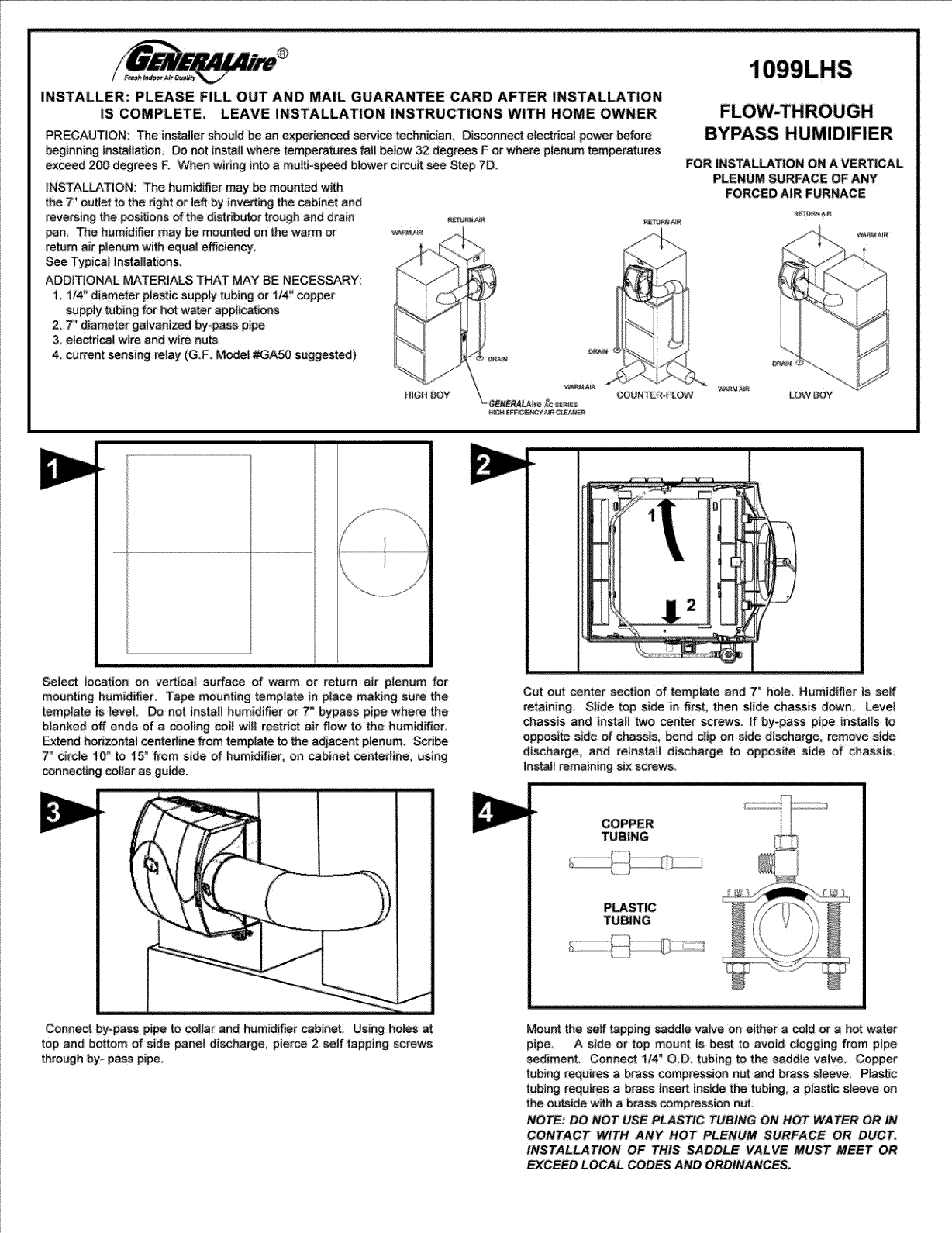
1099LHS
INSTALLER: PLEASE FiLL OUT AND MAiL GUARANTEE CARD AFTER INSTALLATION
IS COMPLETE. LEAVE INSTALLATION INSTRUCTIONS WITH HOME OWNER
PRECAUTION: The instalier should be an experien_d se_i_ technician, Dis_nsect electrical power before
beginning installation Do net instat!where temperatures fail below 32 d_rees F or where plenum temperatures
ex_d 200 degrees E When widng into a mu_i-speed blower circuit see Step 7D
iNSTALLATiON: The humidifier may be mounted with
the T' outlet to the right or !eft by inverting the cabinet and
reversing the posiSons of the distributor trough and drain R_J.._
pan, The humidifier may be mounted on the wa_ or
return air p!enum with equal effiei_cy_
See Typi_l Installations,
ADDITIONAL MATERIALS THAT MAY BE NECESSARY:
_ 114" diameter plastic supp!y tubing or t/4_' copper
Supp_t _abing _r hot water appii_tions
2_ 7" diameter gaivanized E_y-pass pipe
3. electd_t wire and wire nuts
4_ current sensing relay (G.F_ Modes #CA50 suggested)
FLOW,THROUGH
BYPASS HUMIDIFIER
FOR INSTALLATION ON A VERTICAL
PLENUM SURFACE OF ANY
FORCED AIR FURNACE
LOWBOY
Select tocation on vertica_ surface of warm or return air pIenum for
mounting humidifier, Tape mounting temptate in place making sure the
template is ]eve[ Do not tnstaii humidifier or 7" bypass pipe where the
blanbed off ends of a cooling coi_ will restri_ air flow to the humidifier.
Extend horisentat _nterline from template to the sdja_nt plenum, Scribe
7" circle I0" to _5" from side of humidifier_ on cabinet cantedine, using
_nnecting col_ar as guide.
f/j
=
Connect by-pass Pipe to _i!ar and humid_er cabinet.Using holes at
top and bottom of side panei discharge, pierce 2 self tapping screws
through by-pass pipe.
Cut out center section of template _nd 7" ho_e. Humidifier is self
retaining. S|_de top side in first, then s|ide chassis down_ Levei
chassis and instaii two canter screws. !f by-pass pipe instaiis to
opposite side of _assis, bend dip on side discharge, remove s_de
discharge_ and reinstai/ discharge to opposite side of chassis
Instaii remaining six screws.
COPPER
TUBING
PLASTIC
TUBING
Mount the self tapping saddle vatve on either a cotd or a hot water
pipe A side or top mount is best to avoid dogging from pipe
sediment Conne_ 1t4" OD_ tubing to the saddle vatve Copper
tubing requites a brass compression nut and brass s!eeve_ P_astic
tubing requires a brass _nse_ inside the tubing, a plastic sleeve On
the outside with a brass compression nut
NOTE: DO NOT USE PLASTIC TUBING ON HOT WATER OR IN
CONTACT WITH ANY HOT PLENUM SURFACE OR DUCT.
INSTALLATION OF THIS SADDLE VALVE MUST MEET OR
EY.CEED LOCAL CODES AND ORDINANCES°
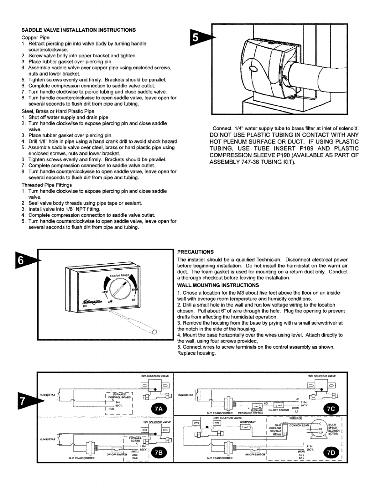
SADDLE VALVE iNSTALLATiON INSTRUCTIONS
Copper Pipe
1. Retract piercing pin into valve body by turning handle
_unterclockwise.
2, Screw valve body into upper bracket and tighten
3, Piece rubber gasket over piercing pin_
4. Assemble saddle ve!ve over cep_r pipe using enclosed screws,
nu_ and lower brackeL
5, Tighten screws evenly end firm!y_ Brackets should be pamiiei,,
6, Compiete _mpression connection to saddie va!ve outiet.
7. Turn handie clockwise to pierce tubing and cLo_ saddle valve.
8. Turn handle counterclockwise to open saddJe valve, leave open for
severe_ seconds to flush dirt from pi_ and tub}ngo
Steel Brass or Hard P!astic Pipe
1_ Shut off water supply and dre!n pipe.
2. Turn handie clockwise to expose piercing pin and dose saddle
valve_
3 Piece rubber gasket over piercing pin_
4_ Ddll _/8" hoJe in pipe using a hand crank ddii to avoid shock ha_rd_
5. Assemble saddle vaive over stee_, brass or hard plastic pipe using
enclosed screws, nuts and _ower bracket.
6. Tighten screws evenly and firmly. Brackets sheutd be paraS{eL
7, Complete compression _nnecflon to saddle vaive outlet_
8, Turn hand!e _unterdockwi_ to open saddle valve_ leave open for
severalsec_ondstoflushdirtfrom pipeand tubing,
Threaded Pipe F_ings
1. Turn handie clockwise to expose piercing pin and dose saddle
vaIve_
2, Seal valve body threads using pipe _ or sealant.
3, Instel_ valve into t/8" NPT _ing,
4. Complete compression connection to saddie valve outlet.
5. Tam handle counterclockwise to open saddle valve, leave open for
several seconds to flush dirt from pipe and tubing
Conne_ _/4" water euppfytu_ to braes flIter at inletof solenoid,
DO NOT USE PLASTIC TUBING _NCONTACT WITH ANY
HOT PLENUM SURFACE OR DUCT. IF USING PLASTIC
TUBING, USE TUBE INSERT Pt89 AND PLASTIC
COMPRESSION SLEEVE P190 (AVAILABLE AS PART OF
,ASSEMBLY 747-38 TUBING KIT),
PRECAUTIONS
The installer should be a qualified Technidan. Disconne_ electrical power
before beginning installatJono Do not instait the humidistat on the warm ,air
duct. The foam gasket is used for mounting on a return duct only. Conduct
a thorough checkout befo_ leaving the installation.
WALL MOUNTING INSTRUCTIONS
1_Chose atocation fo_ the M3 about five feet above the _oor on an inside
wa_lwith average room tem_rature and humidi_ _nd_ions.
2_ Ddil a smail hole in the walt and run iow voltage widng to the |ocation
chosen_ Pul! about 6" of wire through the hole. Plug the opening to prevent
drat_s from affecting the humidistat operation_
3 Remove the housing from the base by p_ing with a smatl screwdriver at
the notch in the side of the housing,
4 Mount the ba_ horizontally over the wires using teveL Attach directiy to
the watt, using four screws provided.
5o Connect wires to screw te_inais on the control assemb|y as shown,
Replace housing.
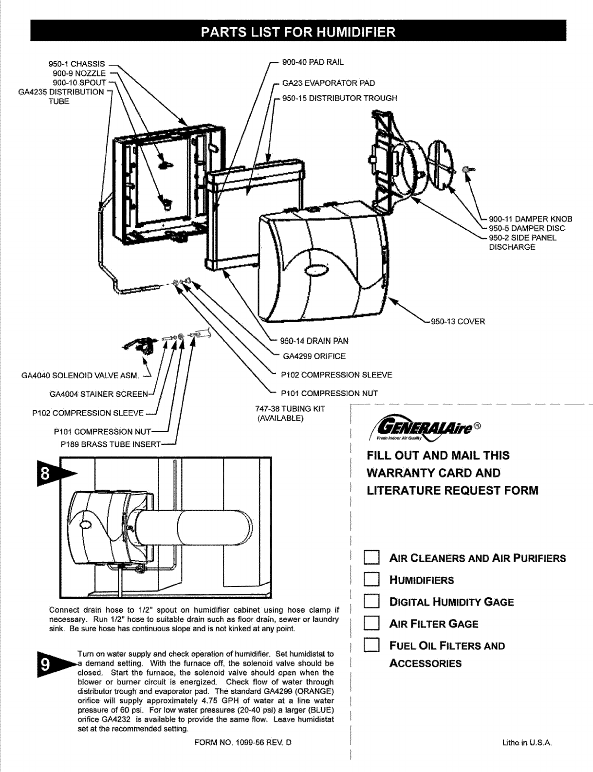
950-1CHASSIS
900-9NOZZLE
900-t0SPOUT
GA4235DiSTRiBUTiON
TUBE
900-40PAD_JL
GA23EVAPORATORPAD
DISTRIBUTORTROUGH
DAMPERKNOB
)ISC
950-2SiDEPANEL
DISCHARGE
P189BRASSTUBEiNSERT--
Connectdrain hose to lt2" spout on humidifier cabinet using hose clamp if
necessary, Run 112" hose to suitable drain such as floor drain, sewer or _aundry
sink, Be sure hose has continuous slope and is not kinked at any point.
Turn on water supply and check operation of humidifier: Set humidistat
demand setting With the furnace off_ the so{enoid vatve should be
dosed. Start the fumace_ the sotenoid valve shoutd open when the
bIower or burner circuit is energized, Check flaw of water through
distributor t_ugh and evaporator pad, The standard GA4299 (ORANGE)
orifice will supp|y approximateiy 435 GPH of water a_ a Jine water
pressure of 60 psL For low water pressures (20`40 psi) a larger (BLUE)
orifice GA4232 is available to provide the same flow. Leave humidistat
set at the recommendedi setting,
FORM NO, ! 099_56 REV_ D
DRAIN PAN
GA4299 ORIFICE
P'I02 COMPRESSION SLEEVE
k"'_ P10! COMPRESSION NUT
747°38 TUB{NG KIT
(A_/AI_BLE)
D
950-13 COVER
FILL OUT AND MAIL THIS
WARRANTY CARD AND
LITERATURE REQUEST FORM
AIR CLEANERS AND AIR PURIFIERS
DIGITAL HUMIDITY GAGE
AIR FILTER GAGE
FUEL OIL FILTERS AND
Utho in US.Ao

Thishumidifier,if propedy registered by the return of the warranty registration cord to the manufacturer, is warranted to the consumer against defec-ts in
matenals and workmanship for aperiod of five years from the date of installation_ Evaporator pads water strainers or metering oririces are not covered
by this !imited warranty or any other warranties Any other defective parts will be repaired w_hout charge except for removai, rein_aiiation and
transportation costs To obtain _pair service under this |ira|ted wa_anty_ the consumer must send the defective part or the _mplete humidifier to the
manufacturer,
THERE ARE NO EXPRESS WARRANTIES COVERING THINSHUM|D|FiER OTHER THAN AS SET FORTH ABOVE, THE IMPLIED WAR_NTIES OF
MERCHANTABILITY AND F|TNESS FOR A PARTICULAR PURPOSE ARE EXPRESSLY EXCLUDED THE MANUFACTURER ASSUMES NO
LIABiLi_ |N CONNECTION WiTH THE tNSTALLAT|ON OR USE OF THiS PRODUCT, EXCEPTAS STATED iN TH|S LiMiTED WAR_NTY. THE
MANUFACTURER W!LL iN NO EVENT BE LIABLE FOR INCIDENTAL OR CONSEQUENTIAL DAMAGES,
This limited warranty gives you spec_c lega! righ_ and you may a!so have other rights which va_ from state to state, Some states do not a!l_ either
iimitations on impiied warranties_ or exclusions from incidenta| or consequenfia| damages, so the above exclusion and iimitation may not appiy to you,
Any questions pertaining _ this iim_tedwarranty should be addressed to the manufacturer. (U S_Ao: The manufacturer has eiected not to make availab|e
the informal dispute se_tement mechanism wM_ is specified in the Magnu_mMoss Warranty Act.)
GENE_L FILTERS, iNC, GENE_ RL_RS, LTD.
NOV|, MICHIGAN 48375-1i15 SCARBOROUGH_ ONTARIO MIR3B7
WWW, GENERA_IRE,COM WWW.CGFPRODUCTS.COM
Your Humidifier is eng!neered to give helpful and troubie_free humidification. For maximum efficiency the re|lowing c|eaning procures should be cerried
out at the end of eac,_ heating season:
1. Turn off water suppty and e|ectrical power to humidifier.
2, Remove cove5 distributortrough_ evaporator pad and drain pan. Clean excessive minera_ deposits from the AT
distrib_or trough, drain pan, pad rai!s_ and humidi_er cabinet. A solution of 1/2 vin_ar & 1/2 water wil| he|p leech OUTSIDE _ECO_ENOEO
minera_ deposits. _MPERATURE SETT|_
3, if theevapomtor pad has excessive mineral deposes, re,ace with a new GA-23 evaporator pad. |nstaU t_ugh and
drain pan. Replace cover, _0°F _9°C 15%
4_ In hea_ minera! areas or if the so!enoid vatve fails to fun_ion disconnect the 1/4" water supp|y line from the -I 0°F -23°C 20%
_lenoid vaive, Carefully puii the strainer screen (PN. GA4004) from the va|ve _dy (P.N, GA4040). Clean the
minera{ de.sits from _!l par_s. !f the or_ce is dogged, it may be opened by inserting asmal_ pin_ Reinsert the fi|ter 0°F -18°C
intothe orifice ri_tting and screw the brass strainer body into the se|enoid valve, +10_F -29°C 30%
5, Re_nnect the !/4_' water !|no to the solenoid valve if necessary_ Turn on the water suppiy and check a!l p_nts for
_eakage. The operation of the un_ may _ check_ by sta_ing the furnace. The humidifier operates only when the +20OF "7°C
furnace bl_er is running or the _mer circuit is energized. The humidifier is now ready for operation. +30°F -1°C 40%
6, Ounng the summer_ t_m off wa_er s_pply and eiectrice| power to humidff_e#. Ciose air dampe_.
m
Z
DO
Zz
Z_
OZ
z
O
.?
Z
O
DO
m r-
co_
_<
rn
The operating principie of the humidi_er is based on the most efficient
and economicel means of evaporating water to the air The humidiher
uses onty 2.5 watts of e|ectd_| power during operationi le_ than the
smat_est household light bulb The heat necessa_ for evaporating water
is produced by the furnace.
The water suppIy to the humidifier is controlled by the electdc solenoid
valve_ The humidistat _nnected in series with the so|enoid provides _w
voltage _ntro! of the humidifier_ The humid|star }s designed for wall
mounting _n the living area or surface mounting on the return air duct,
ELEC-TR|CAL RATING: 24 VAC !60 Hz_
DO NOT SET RELATIVE HUMID_TY TOO HiGH DURING COLD
WEATHER_ _×CESSWE HUM|DITY MAY CAUSE CONDENSATION ON
WlNDC_'NS OR |N WALLS, REFER TO RECOMMENDED SETTINGS
AS DESCR|BED 1NTHE HUMfD_STAT OWNERS MANUAL
Water flows through astrainer, is metered through an orifice to provide
the proper amount of water, and is supplied to the evaporator pad by the
distributo_ trough. Approximately 200 CFM of air is by=pass_ from the
warm air plenum through the hum_d_her and returned to the cold air
p_enum Moisture is evaporated to the air passing through the evaporator
pad
Minerals are not bi_n into the air stream aS occurs in atomizJng
hum3d_ers; they are _eft on the evaporator pad where a high _rcentage
is cerri_ off w_h the waste water,:
When the humidifier _s instal|ed and operating, no adjustments are
necessa_ other than setting the centre| knob on the humidistat to the
desired level of humidification. Leave knob on the humidifier in "Hi" or
"W|NTER" position
To turn the humidifier off, dose water suppty va|ve, switch el_dca!
power off and turn humidistat off if furnace {s _sed for summer cooling or
venti|ating set air damper on %OW" or "SUMMER",

DERIVATION VENTILEE
INSTALLATEUR : VEU|LL_ REMPLIR ET POSTER _CARTE DE GARANT|E UNE FOIS L'|NSTALLAT|ON
TERMIN_E_ LAISSER LES DiRECTiVES D'iNSTALLATION AU PROPRI_TAIRE DE LA MA|SON.
PReCAUTiON : L!ins_ilateur doit _tre un t_hnicien qual_6 et exp6riment_. Couper I'atimentation 61_dque
avsnt de commencer iinstsHstion, Ne pas ins|aider Ysppareii dsns un endro_ o_ Js temp6rsture peut descendre POUR UNE iNSTALLATiON SUR LA
SURFACE VERTICALE DU PLENUM DE
_us 0 "C (32: °F) ou si is temp6rature du pl6num d6pssse 93 °C (200 °F). Lore d'un brsnchement & un circuit de N'IMPORTE QUELLE FOURNAISE A AiR
ventilsteur _ plus|curs vitesses, voir _'_tape 7D.
iNSTALLATION: Uhumidtficstsur devrsit _tre mont_ svec le d6bouch6
de 7 _ _ gauche ou _ droite, en inverssnt Is bo_tier et lee positions de
_sgoulottedudistributeuretdubacdevidsnge_ L!humidificsteur foum_t
_e m6me rendement_ qu'i! soit instalJ6sur un pl6num d'air ¢hsud ou sur
un pl6num de reprise d'air_ Voir les installations Typtques_
MAT_RIAUX ADDIT_ONNELS POUVANT _TRE REQUIS :
1. 'Tuba d's_imentation en plastique de lt4 pc de diam,|re ou
tube d!alimentstion en cuivre de 1/4 pc pour lee applications
pour esu chsude
2_ Tuysu de d6rivation gslvsnis6 de _5 cm (6 pc)
3: fit 61ectnque et ssrre-fits
4. Commutateur de pression d'sir (GE msd_ie n °12500 sugg6r6)
C_UD PROPULSE
SOg$.,SOL
D6cou_r la section centrs!e de _a m_tri_ et le tro_ de 7 po, Le
ch_ss}s _e rhumidfficateur est a_tonome; ins6rer la parle
sup6rieure en !a g{isss_t, puis fsire g_isser to_t te chassis vers _e
bss. Les ch_,ssts de niveau et instalment_s vis cent_ales. Si la pipe
insta_!e sur |e c6t_ oppos6 du ch_ssis, agrsfe _e fl6chissez sur |e
chassis0 enievez is eerie fst6_le, et instaiiez s_r ie c6t6 oppo_ d_
ch&ssis. Ins_Hez _essix vis restantes.
J
Connecter !e tuya_ de d_ivation su cotiier et s_ bo_t_er de
rhumi_i_teur.
En _tiiisant lee tress en hau| et ie fond de _asortie, percez de_x vie par
ia pi_,
TUYAUX EN
CUIVRE
TUYAUX EN
P_S_QUE
Menter _e robinet_vsnne _ _rier s_totatsudeur sur un tuya_ d'es_ eha_de ou d'eau
freide Un menage _st_ra_ o_ sur le _essus es_ id_s_ pou_ 6viter ur_ engorgement
_us6 par |es s_diment_ d_ _yau. Conne_er un t_yau d!un diam,, e×t; de6 mm (1/4
ps} au robinet-vanne _ _._er. Lee tuysu× en cuivre exigent un 6crou _ _mpte_ion
et un msnchon en/aiton. Les tuyaux en p_astique exigen_ un insert en laito_ b
l'tnt_rieur des tuyaux et gn manchon an ptasttque _I'ext6rieur sve¢ un _cro_ b
compression, REMARQUE : NE PAS UTILISER DE TUYAUX EN PLASTIQUE
AVEC DE L*EAU CHAUDE OU SUR UNE SURFACE DE CONTACT CHAUDE DE
PLENUM OU DE CONDUI_ L'INSTALLATION DE CE ROBINET-VANNE A
_TRIER DOlT TER OU D_PASSER LES EXIGENCES DES CODES
LOCAUX _AUTRES ORDONNANCES,
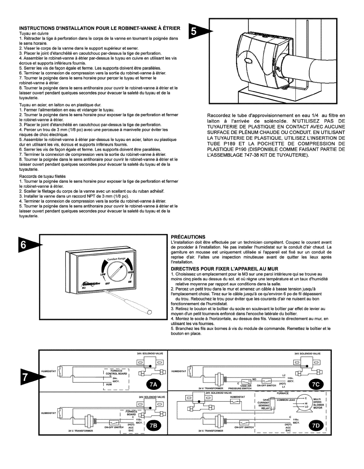
INSTRUCTIONS D'INSTALLATION POUR LE ROBINIET-VANNE A I_TRIER
Tuyau en coivre
R_t_acter _atJge _ performlon dana Io corps de _ayunna en toumant Is po_gnee dana
]e sees horaire.
2. Vissar le corps de la vanne dana le support supeneur et sorter.
3P_ocer Je joint d'_tanch_ite en caoutchouc parodessua ta tJge de Deffora_en.
4. Assembler Jarobinet_vanne _ _riet par4:tesaus ie tuyau en cu_vre en ut_ii_nt lea via
Cereus et supports inf_rieurs foumis
5 Sorter lea via de fa_n _gale et ferme. Lea eupporL_ doivent L_trepara{l_le&
6, Terminet la connexion de compression vats _ so_fe du robmet_vanne a eme_
7 Tourr_t _a_ign_e dana le sen_ hotaire poDr perce_ Io tuyau et former le
rebinet=vanne a _tnet,
8. Tourney" la _lgn_e duns le _ns anfiheraire pour euvdt le rebmet-vanne _ _r_t et le
]tosser euvert pendant quelques s_ndes pour evacuer la salete du tuyau et de Is
tuyautene
T_yau en actor, an laiten e_ en plastique dur.
Former t'alimentation en eau et vi_ge_ le _uyau
2 Teur_r {a poIgn_e dan_ _eser_ hotaire po_r exposer _afJgo de oederabon e_ former
le robinet-vanne b_trier,
3_ Pincer le joint d'(gtanch_it_ en caoutchouc par_lessus ts tige de perforation
a Percer un trou de 3 mm (I/8 #o) avoc une perceuse a man_vel_e pour evitet {as
nsq_es de choc eleetnque_
5.Assembler _erobinet-vanne _ _:ner parnassus _etuyau en ac_et, laden ou #_ast{que
duten uti]isant leavia _reus et supportg _n_rieurs faum_s
6. Sorter _es ws de fa_n egale _ ferme. Lea supports doivent _re parallaxes.
7. Term_ner la connexion de compression vers _asortie du teb_net-vanne a &trie_
& Teurner {a po_gnee clans _esees antmoraite pour ouvnr _e tobmet-vanne a ether et le
laisser ouve_t pendant quelques _o_de_ pour _vac_r _asale_6 du tuyau et de _a
tuya_eae.
Raccords de tuyau filet_s
I Tourner _a PenanCe dana _esons hota_re po_r exposer _at_ge de perforation e_ fe_mer
le rob_netovanne b_der.
2_ ScePter le filetago dD corps de la vanne avec un sceHant eu du ruben adh_mf
3 Installer _a vanne dana un raccord NPT de 3mm( U8 po)
4 Terminet Is connexion de compression vers _asortie _u rebinet-vanne _ _tner
5. Tourner _apoignee dana le sees antJhoraire pout ouvn/_e robmet-vanne _ etrier et le
la_sser ouvert pendar_ _ue_que_ _ndes pour _vacuer _asalet6 du tuya_ et de }a
tuyautene
Raccotdez le tube d'approvisiennement en eau 114 au flltre en
latton & rardvee de soleno_de. N°UTILISEZ PAS DE
TUYAUTERIE DE PLASTIQUE EN CONTACT AVEC AUCUNE
SURFACE DE PLENUM CHJ_UDE OU CONDIJ{T_ EN UT_USANT
LA TUYAUTERIE DE PLASTIQUE UTILISEZ U_NSERTION DE
TUBE P189 ET LA POCHETTE DE COMPRESSION DE
PLASTIQUE Pt90 (DIBPONI!BLE COMME FAISANT PANTIE DE
UASSEMBLAGE 747-38 KIT DE TUYAUTERIE),
PRECAUTIONS
L'ms_i_atJon d0it _t_e effectu_ par un technician competent Coupez Ie courant event
_e preceder _ I°inatallation; Ne pus instailer _'hDmidist_ _r _e conduit d'ait chaud_
garniture ee mous_ eat uniquement Dtiti_ si rapparei_ e_ fi×6 sDr Dn _ndDit de
repdse d'a_r. Faftes une inspect}on mfn_eu_ ava_ de _u_er _es iieu× apres
I'ies_lation
DIRECTIVES POUR FIXER L'APPARE|L AU MUR
"1 Chais_ssez _n em_acement pour _ M3 _r _ne pardi int_rieure qui_ _ro_ve au
roBinS _nq pieds aD dessDs d_ _L et ou r_gne une tem_rature et _ta_ d'hgmk_it_
relative moyenne pat _ppoA aux cond_iona dens _asalie.
2 Perce_z _n petit tro_ dana le mot _ amenez Dn r__b_e_ basso te_sioe _squ_b
_'emp_aeement chDisL _rez sur !e _b_e jusqu'_ _ qu'envi_'on 6 po _e fi! depessent
du trod ReboDchez le trod pour _v_er qDe les _urante d'air ne nuisent au bDn
fen_onnement de _'hum_distat.
3 Retirez _e bDDto_ et le bo_tier de _cle en _ulevant }e bo_t_et per offer de fevier aa
meyen d'unpetit to,morris e_on_ dane l'encoche taterale dU bo_be[
& Memez ie soda _ _'he_zonta_e, au dess#s des fil_&Wssez4e directement au tour, en
utiiisamleaviafournies
5. 8ranchez _es file aux boreas _ via dD module de commande; Remettez ie heatheret le
bouten en p_ace.
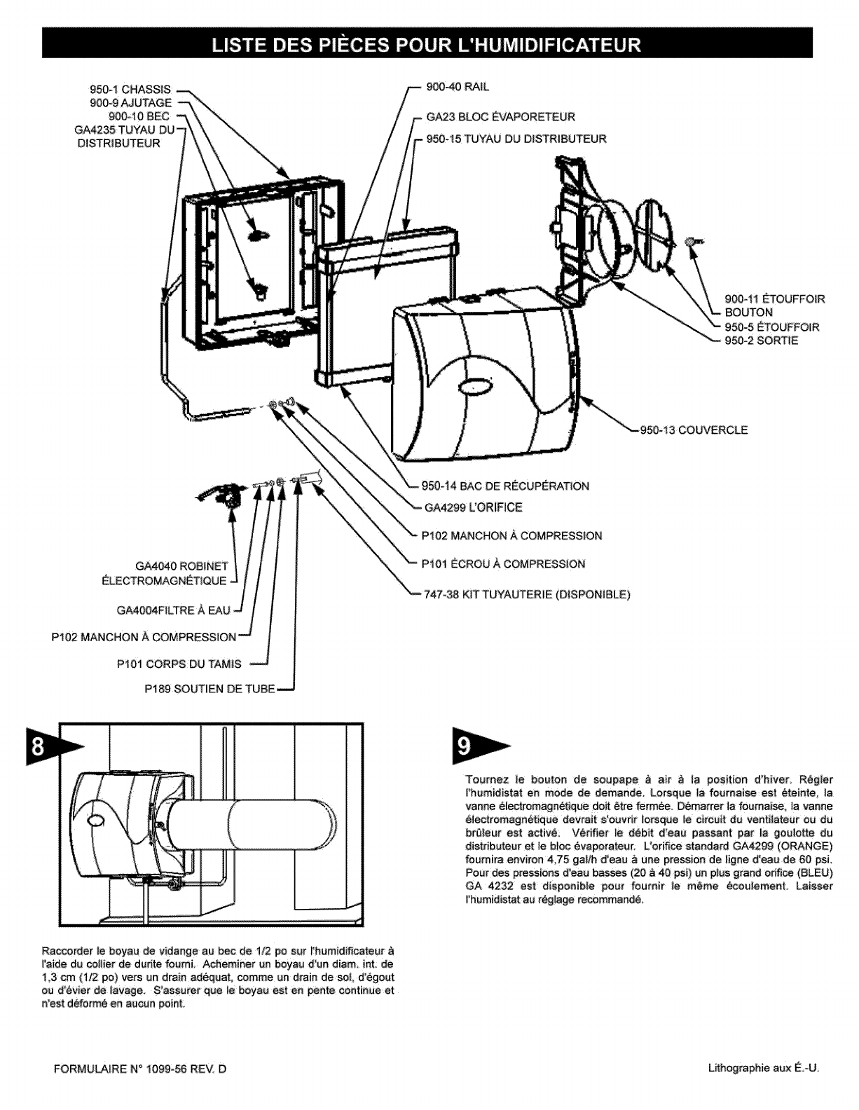
950-1 CHASS|S
900-9 _ UTAGE
900ot 0 BEC
GA4235 TUYAU
D_STRlBUTEUR
900-40 _IL
G_3 BLOC _VAPORETEUR
TUYAU DU DISTRIBUTEUR
900-11 _TOUFFOiR
BOUTON
950=5 _TOUFFO;R
950°2 SORTIE
-950_13 COUVERCLE
P101 CORPS DU TAMIS
P189 SOUTiEN DE TUBE---.J
BAC DE R_CUP_RATiON
Pi01 _CROU A COMPRESSION
KiT TUYAUTER_E (DISPON_BLE)
'Toumez ie bouton de soupape _ air _ ia position d'hiver. R_giet
I_humidistat en mode de demande. Lorsqae !a foumaise est _teinte, la
vanne eiectremagnefJque doit 6tre ferm6e. _marrer ta feumaise. {a vanne
electremagnetique devrait s'ouvdr lersque le circuit du ventilateur eu du
bra|eur est active: V_riSer le d_bit d'eau passant par la goutotte du
distdbuteuret le b_ec _vaporateur, L'ori_ce standa_ GA4299 (ORANGE)
foumira environ 4,75 gallb d'eau _ une pressien de iigne d'eau de 60 psL
Pour des pressiens d'eau basses (20 _ 40 psi) un pius grand or_ (SLEU)
GA 4232 est dispeeibte pour foumir }e m6me _ouJement. Laisser
l'humidistat au r_glage recommend6,
Raccorder le boyau de vidange au bec de 112 po sur !!humidificateur
_'aide du coIHer de dudte feumi, Achemtne_ un b_au d'un diem int: de
i ,3 em (1_ po) vers um drain ad_quat, comme un drain de sol, d!_gout
ou _'_vier de lavage. S'assut_er que le boyau est en pente continue et
n'est deform_ en a_¢un poin_i
FORMU_IRE N° 1099=56 REV. D L,ithographie aex _.-U
Cothumidi_cateur,s_iiest enregistr6 correctement en retournant ia carte d'enregistrement de ta garantie au fabriquant, est garanti au _nsommateur
centre tout defsut de matenaux et de main d'oeuvre pour une _riode de cinq ans _ par|Jr de la date d'instailation. Garnitures de vape_sateur, ecrans de
tamis de i'eau ou orifices regulateu_ ne sent pas oouverts par cette garantie fimitee ou par route autre garantie, Toute autre piece defectueuse sera
reparee sans frais_ hormis !es co_ts de d_sinsta!iation, de reinsta!iation et de transport. Pour Obtenir un service de reparation avec cette garant_e limit_e,
le consomme|ear dolt envoyer |a piece defectueuse ou I'humidificateur au templet au fabricant.
IL N'Y A AUCUNE GA_NTIE _PRESSE COUVRJkNT CE PURIHCATEUR D'AiR EN DEHORS DES DiSPOSiTiONS STIPUL_ES C|-DESSUS_ LES
GARANTIES TACiTES QUANT A _ QUALiT_ MARCHANDE ET A L'APTtTUDE A UN EMPLOI PART|CUUER SeNT EXPRESS_MENT E×CLUES. LE
FABRiCANT NE PEUT _TRE TENU RESPONSABLE POUR L'_NSTAL_TION QU L'UT|LiSAT_ON DE CE PROD_JIT, SAUF DE LA MANI_RE
{NDiQU_E DANS LA PR_SENTE GARANT_E LIMiT_E. LE FABR|CANT NE PEUT EN AUCUN CAS _TRE TENU RESPONSABLE POUR DES
DOMMAGES ACCESSOiRES OU INDiRECTS:.
Cette garantie !imitee vous donne des droits t_gau× sp_cffiques et vous pouvez jouir d'autres droits qui varient d'une juridic|ion _ i'a_tre= Co,sines
j_ridi_ions ne permettent pas de iimites s_r los garanties impiicites ou d'exc_sions pour les dommages accesso|res ou indirects; |es exclusions s_s
mentionn_s pe_vent done ne pas s'appli_er dens re|re cas_
Toute question reietive _ cette garantie |imitee doit _tre so_mise au fabr_quant. (_°_U_ : Le fabricant _ choisi de ne pas divuig_er _estermes de |'acco_
speci_s dens _e"Magn_somMoss Waranty Act 'L)
GENE_L FALTERS, INC.
NOV|, MICHIGAN 48375-_ii5
WWW,GENE_iRE.COM
GENERAL RLTERS, LTD_
SCARBOROUGH, ONTARIO MIR3B7
WWW_CGFPRODUCTS,COM
Votre h_m_dificate_r est conc_u pour foumir une humidification d!appoint sans probiemes. Po_r _neficier dun fonctionnement ma×im_m; s_ivre ies
_tapes de nettoyage c{<_essous & ia fin de cheque seison froide !
Fe_er ra_imentation en eau et en _lectncit_ de _'humidificate_r.
2:, Rotifer _etuya_ de distribution d'ea_, {e bac d_ d stn_te_5 le tampon d'_va_te_r et _ebac de _c_p_ration Le _
|amen d!_va_te_r _t _tre en_eve du haut ou du _s de i'humidificateur. Nettoy_ les d_pSts excessi_ de mineraux TEMP_PJ_TUR_
dens _e bac _u dtstributegr, _ecouvercle, tebac de rL_cu_ration, e_ le hot'tier du distributeur. Une solution moiti_ vinaigre, EX_tEU_
moiti_ eau aide & d_!oger les d_pSts de min6ra_x_
3. Si ie bl_ _va_rate_r con|ion| trop de d_p6ts de mineraux le rempiacer par un neuf" GAo23 ". Repta_r le couverde _0°F -29_0
et le tuyau d_ distdbuteur _ !a _sition adequate par dess_s le bac _u dis_buteur .!0OF .23_0
4, Dens los endroits riches en min_raux eu s_ la vanne eiectromagn@Jque est d_fat_ante, d_connec_er _a|igne
#a|imentation en ea_ de 6 mm (I/4 po) de la vanne _ectromagn_tique Rotifer _eco_s de _mis en taiton (P.N. 99-0-t8) 0°F -18°O
de I'electrovanne Retirer soigneu_ment le ill|re & tamis (P.N_ GA40_) du _ord de 1'otifice (P_N. GA404O)_ Nettoyer +10OF .29oc
les d_p6_ de minera_ de,routes les pieceso Si i'orifice est bloqu_, on pe_t I!ouvdt en y in.rant une pe_te aig_tl_e. +20oF.7o C
R_ins_rer le ill|re dens |e rac¢_rd de !'e_ et visser _e _ps de tamis en taiton darts |"_tec_revanne
5 Raccorder la cond_ite d'eau de 6mm (_/4 _) _ la vanne _iectromagn6tique au _soin. Ouvrir I'aiimentation eo ea_ et +30_F - 1°C
verifier te_ tes points de fuite. Le fonctionnement de t'apparei_ peut _tre ve_ifi_ e_ d_marrant la foumaise
L'humidificateur fonctionne uniq_ement Io_q_e le ventitateur de ia fournaise est en marche o_ q_e le circuit dg btQ|eur
est activ6. L'humidi_cate_r est maintenant pr_t _ fenctionner_
6. Pendant la p_ri_e d'_t_ former regimentation en eau et en _ectricitL, de i_h_midificateur. Fe_er }'amortisseur _ air.
_GLAGE
15%
20%
25%
30%
35%
40%
Le principe de fonctionnement de i'humidificateu_ est bas_ sur la fa_;_n la p_use_cace et la plus _cenemique d'_va_rer I!ea_ dens i'air. L'humidificateur
utili_ _niquement 2;5 watts de cou_nt _ectrique Iorsqu'il fon_onne, c'est-&-d_re moins que |a p_us petite ampoule _ectriq_e de votre maison.
chaieur n_cessaire pour l'_vaporation de I'ea_ est produite pa_ _afoumaise.
L'alimentation en eau ve_ l'humidificateur est contr6|ee par la vanne _|ectromagn_tique. L'h_midistat conne_ en s_rie avec ia "#anne
_lectromagn_tique foumit un contr6!e de basso tension _ _'h_midificateur, L'h_midostat est _n_ _ur un montage mural dens !'espace habitable ou un
montage de surface sur te _nduit de reprise d'air. CARACT_R|ST_QUES _LECTR|QUES : 24 V c.a. /60 Hz.
NE PAS R_GLER L'HUMIDIT_ RELATIVE TROP HAUT PENDANT LA P_RIODE H|VERNALE TROP D!HUMiDIT_ PEUT ENTRA_NER DE LA
CONDENSATION SUR LES VlTRES OU SUR LES MURS CONSULTER LES R_GLAGES RECOMMAND_S, D_CRITS DANS LE MANUEL DU
PROPR]_TAIRE DE UHUMIDOSTAT.
L'eau s'_couie par une cr_pine, est mesuree par un o_i_ce pour foumir _a q_antite adequate et atimente |e b|oc _vaporate_r _r |a gou!otte du
distrib_te_r. Environ 5_66 m_tres cubes par minute st d_n_v_ du p_num d'air chaud, passe pap |'h_midificateur etest renvoy_ au plenum d'air froid,
L'humidite est _va_ree dens I'air en passant par le bl_ _vaporateur_
Los mineral× ne _nt pas souses dens _e courant d'air, comme C'es_ ie cas avec los humidificate_rs bpu|verisetion; i_srestent sur le bloc 6vaporateur
o_3un fort pourcentage est evacue ave¢ !es e_u× us_es.
Lorsque i'humidificateur est ins|alto et fonct_onne_ aucun r_giage n_est n_cessaire sauf te tog|age du niveau vou|u d_h_midification pap le beaten de
_mmande sur i'h_m_distaL Laisser le _uton de i'humidificateur a ia position "H|" ou "WINTER"
Pour _eindre i'humidificateur, former !a vanne d'alimentation en eau_ met|re ho_ tension et former |'humidistat, Si |a chaudi_re sort au refroidissement
ou _ ta ventilation en _t_, _ler I'amortisseuP d'air sup "LOW°'ou "SUMMER",
