Genie CM7600 User Manual AC SCREWDRIVE GDO Manuals And Guides L0703289
GENIE Garage Door Opener Manual L0703289 GENIE Garage Door Opener Owner's Manual, GENIE Garage Door Opener installation guides
User Manual: Genie CM7600 CM7600 GENIE GENIE AC SCREWDRIVE GDO - Manuals and Guides View the owners manual for your GENIE GENIE AC SCREWDRIVE GDO #CM7600. Home:Garage Door & Opener Parts:Genie Parts:Genie GENIE AC SCREWDRIVE GDO Manual
Open the PDF directly: View PDF ![]() .
.
Page Count: 35

Check your ceiling where the power
head of your new unit will be mounted.
Plan how you wilt be mounting the power head.
It is possible that ceiling joists may not be in the
exact position needed with respect to the garage
door operator. It may be necessary to add an
additional bracket and fasteners (not included
with your new door operator kit).
Check the wall directly above the garage
door. The door operator's header bracket
must be securely fastened to this watt. Ensure
that the structure wilt provide a strong mounting
location.
Check to see if the mounting location
for the Safe-T-Beam ® System (STB) is
clear from obstruction and has a wood
surface available for attaching the STB brack-
ets. The brackets may be attached to concrete if
necessary but extra tools and special fasteners
(not supplied) will be required.
b_O'l" : 1-12 STB b_'_ck_:;£sd_;U_t_'s _;
You need a 110-120 Volt power supply
available. The outlet should be no more than
3 feet from the power head once it is mounted. (The
cord is 4 ft. in length.) SEE WARNING BELOW.
To avoid damage to your door and/or
operator, make sure you disable any door
locks prior to installing your operator.
Ensure that your door is properly balanced
and moving freely. SEE WARNING BELOW.
(NOT SHOWN) If your garage does not have
a separate entry door, you should consider
an emergency release kit (GER-2) for installation
on your garage door. See page C at the center of
this manual.
Is your garage door made of
light-weight steel, aluminum, fiberglass
or glass panels? Additional support bracing
must be added to these type doors. If this is the
case, please contact the door distributor or
manufacturer so that they can furnish you with a
"bracing kit."
,omeLink® is a universal
transceiver (a combined
transmitter and receiver), that provides a
convenient way to replace up to three hand-held
radio-frequency (RF) transmitters used to
activate devices such as gate operators, garage
door openers, entry door locks, security systems
and even home lighting. Additional HomeLink ®
information can be found at: www.homelink.com
or by calling 1.800.355.3515.
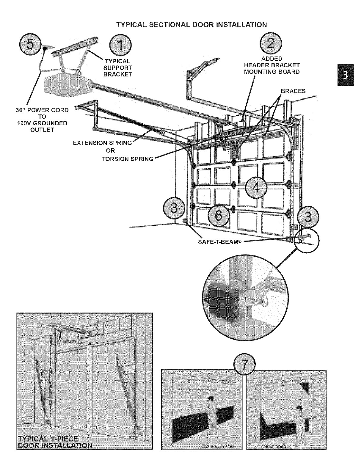
TYPICAL SECTIONAL DOOR iNSTALLATION
SUPPORT
BRACKET
ADDED
HEADER BRACKET
MOUNTING BOARD
BRACES
36" POWER CORD
TO
120V GROUNDED
OUTLET
EXTENSION SPRING
OR
TORSION SPRING
SAFE=T-BEAM®
II
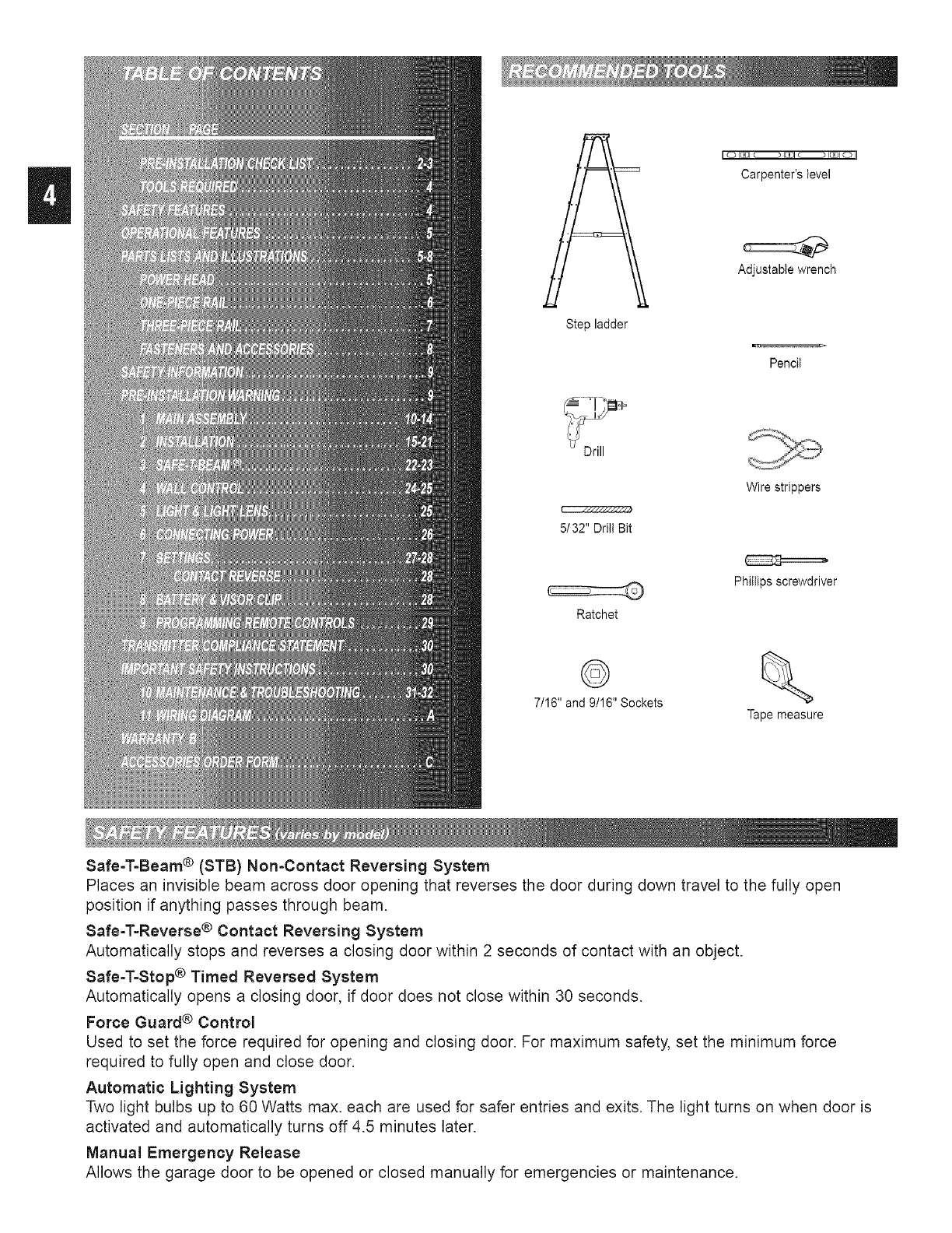
Safe-T=Beam ® (STB} Non-Contact Reversing System
Step ladder
5/32" Drill Bit
Ratchet
©
7/16" and 9/16" Sockets
I {:D I[Z31@ I_1 (:_) I_DI O II
Carpenter's level
Adjustable wrench
Pencil
Wire strippers
Phillips screwdriver
Tape measure
Places an invisible beam across door opening that reverses the door during down travel to the fully open
position if anything passes through beam.
Safe-T=Reverse ®Contact Reversing System
Automatically stops and reverses a closing door within 2 seconds of contact with an object.
Safe-T=Stop ®Timed Reversed System
Automatically opens a closing door, if door does not close within 30 seconds.
Force Guard ®Control
Used to set the force required for opening and closing door. For maximum safety, set the minimum force
required to fully open and close door.
Automatic Lighting System
Two light bulbs up to 60 Watts max. each are used for safer entries and exits. The light turns on when door is
activated and automatically turns off 4.5 minutes later.
Manual Emergency Release
Allows the garage door to be opened or closed manually for emergencies or maintenance.
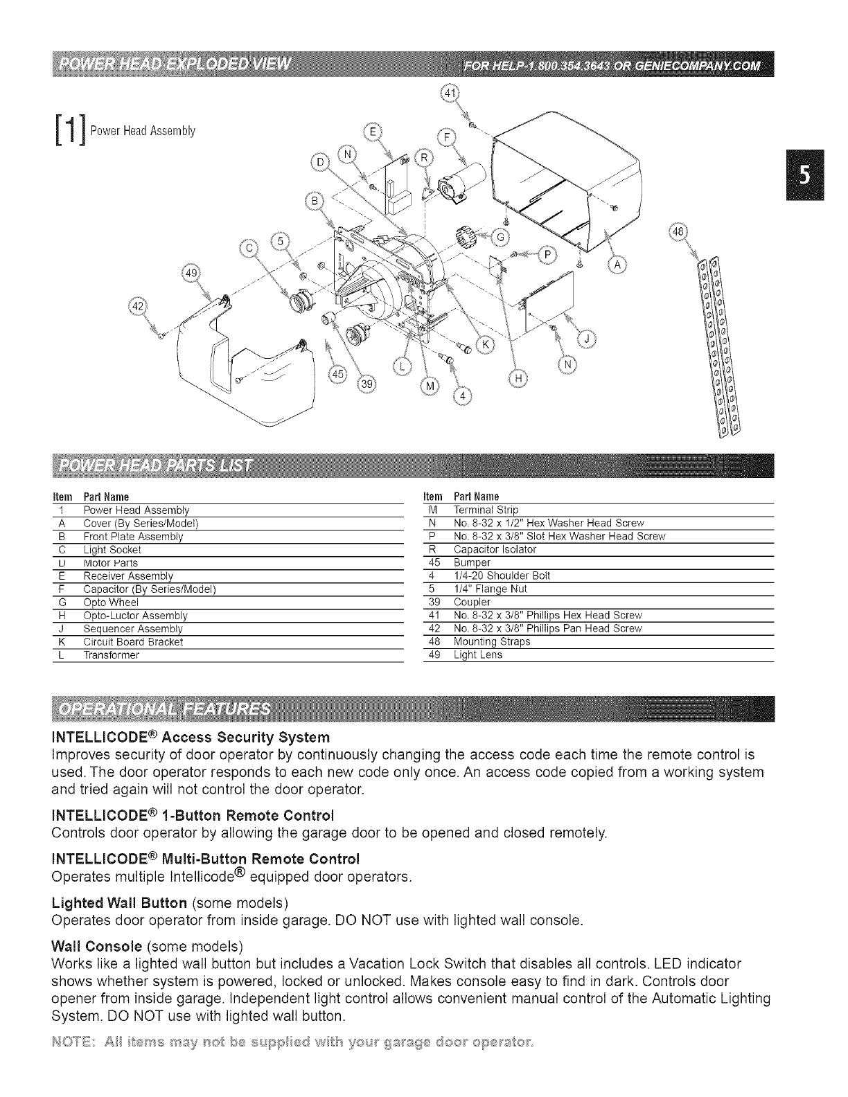
[1]P0werHeadAssemb,y
Item Part Name Item Part Name
1 Power Head Assembly M Terminal Strip
A Cover (By Series/Model) N No. 8-32 x 1/2" Hex Washer Head Screw
B Front Plate Assembly P No. 8-32 x 3/8" Slot Hex Washer Head Screw
C Light Socket R Capacitor Isolator
U Motor Harts 45 Bumper
E Receiver Assembly 4 1/4-20 Shoulder Bolt
F Capacitor (By Series/Model) 5 1/4" Flange Nut
G Opto Wheel 39 Coupler
H Opto-Luctor Assembly 41 No. 8-32 x 3/8" Phillips Hex Head Screw
J Sequencer Assembly 42 No. 8-32 x 3/8" Phillips Pan Head Screw
K Circuit Board Bracket 48 Mounting Straps
L Transformer 49 Light Lens
INTELLICODE ® Access Security System
Improves security of door operator by continuously changing the access code each time the remote control is
used. The door operator responds to each new code only once. An access code copied from a working system
and tried again will not control the door operator.
INTELLICODE ® l-Button Remote Control
Controls door operator by allowing the garage door to be opened and closed remotely.
INTELLICODE ® Multi-Button Remote Control
Operates multiple tntellicode ® equipped door operators.
Lighted Wall Button (some models)
Operates door operator from inside garage. DO NOT use with lighted wall console.
Wall Console (some models)
Works like a lighted wall button but includes a Vacation Lock Switch that disables all controls. LED indicator
shows whether system is powered, locked or unlocked. Makes console easy to find in dark. Controls door
opener from inside garage. Independent light control allows convenient manual control of the Automatic Lighting
System. DO NOT use with lighted wall button.
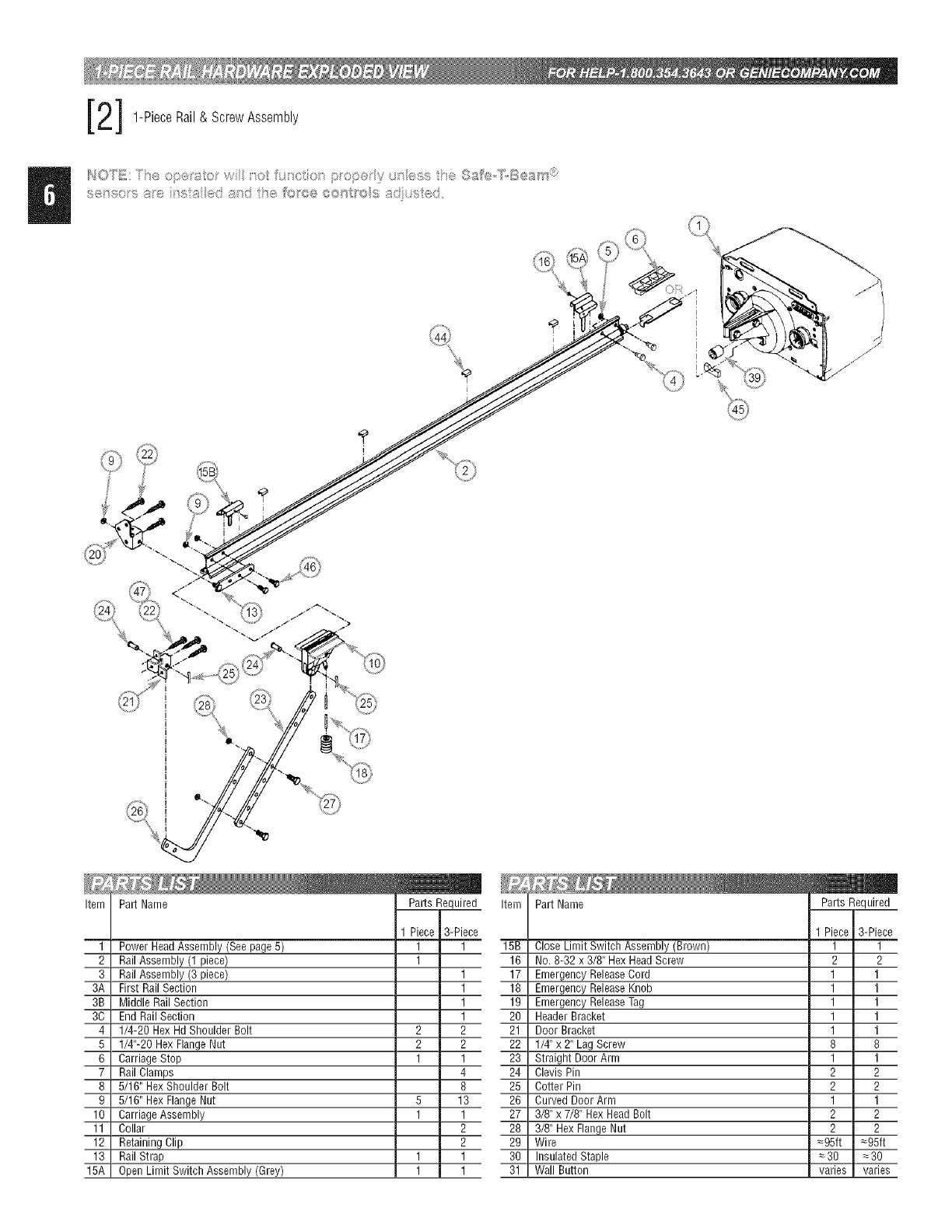
2] 1-PieceRail& ScrewAssembly
,.,,, =.., =.., ,s*, Ii]I;,IIQIIII!CI....... = = ....... ........ ...........
Item
1
2
3
3A
3B
3C
4
5
6
7
8
9
10
11
12
13
15A
Part Name Item
3-Piece
Power HeadAssembly(Seepage5) 1 1 15B
RailAssembly(1 piece) 1 16
RailAssembly(3 piece) 1 17
First RailSection 1 18
Middle RailSection 1 19
End RailSection 1 20
1/4-20 HexHdShoulder Bolt 2 2 21
1/4"-20 HexFlangeNut 2 2 22
CarriageStop 1 1 23
RailClamps 4 24
5/16" HexShoulderBolt 8 25
5/16" HexFlangeNut 5 13 26
CarriageAssembly 1 1 27
Collar 2 28
RetainingClip 2 29
RailStrap 1 1 30
OpenLimit SwitchAssembly (Grey) 1 1 31
Part Name
3-Piece
Close Limit Switch Assembly(Brown) 1 1
No. 8-32 x 3/8" HexHeadScrew 2 2
EmergencyReleaseCord 1 1
EmergencyReleaseKnob 1 1
EmergencyReleaseTag 1 1
HeaderBracket 1 1
DoorBracket 1 1
1/4"x 2" Lag Screw 8 8
Straight DoorArm 1 1
ClevisPin 2 2
Cotter Pin 2 2
Curved DoorArm 1 1
3/8" x 7/8" HexHeadBolt 2 2
3/8" HexFlangeNut 2 2
Wire _95ft =95ft
InsulatedStaple =30 _30
Wall Button varies varies
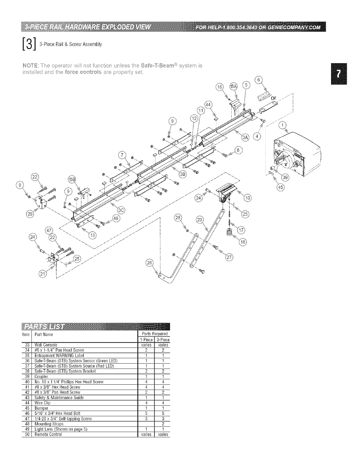
3]3-PieceRail&ScrewAssembly
8 _i ....... s.... w::; 8_;, >O>@Yd
Item
33
34
35
36
37
38
39
40
41
42
43
44
45
46
47
48
49
50
Part Name
Wall Console
#6 x 1-1/4" PanHeadScrew
EntrapmentWARNINGLabel
Safe-T-Beam(STB)SystemSensor (GreenLED)
Safe-T-Beam(STB)SystemSource (RedLED)
Safe-T-Beam(STB)System Bracket
Coupler
No. 10 x 1 1/4" Phillips HexHeadScrew
#8 x 3/8" HexHeadScrew
#8 x 3/8" PanHeadScrew
Safety & MaintenanceGuide
Wire Clip
Bumper
5/16"x 3/4"Hex HeadBolt
1/4-20 x 3/4" Self-tappingScrew
Mounting Straps
Light Lens (Shownon page5)
RemoteControl
varies
2
1
1
1
2
1
4
4
2
1
4
1
5
3
1
varies
3-Piece
varies
2
1
1
1
2
1
4
4
2
1
4
1
5
3
2
1
varies

U@@®
@
remotes
vary
by model @
_m
..... _ .i}:..//,ii
.... y
FASTENERS =Shown full size. See Parts List for description.
D.J l
q--
1/4" Shoulder bolt w/flange 1/4" x 2" Lag screw Coupler
©
1/4" Flange nut
Carriage stop (net to scale)
8/16" Shoulder bolt w/flange
g (8)
5/16" Flange nut
tn @
Collar
Clevis pin
Cotter pin
,21
3/8" Hex head bolt
3/8" Nut_
Insulated staple
#10 x 1-1/4" PhilHps hex head screw
N
#8 x3/8" Hex flange head screw
N
N
#8 x 3/8" Pan head screw
Wire clip
Rubber bumper
Clip
NI Nt
5/16" x 3/4" Hex head bolt
#8-32 x 3/8" Hex head screw #6 x 1-1/4" Pan head screw
j_
1/4"-20 Self-drilling screw
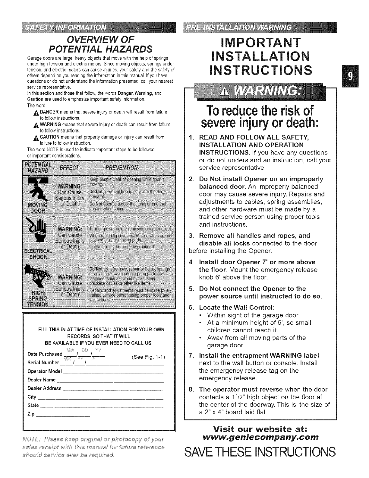
OVERVIEW OF
POTENTIAL HAZARDS
Garage doors are large, heavy objects that move with the help of springs
under high tension and electric motors. Since moving objects, springs under
tension, and electric motors can cause injuries, your safety and the safety of
others depend on you reading the information in this manual, if you have
questions or do not understand the information presented, call your nearest
service representative.
in this section and those that foilow, the words Danger, Warning, and
Caution are used to emphasize important safety information.
The word:
,_ DANGER means that severe injury or death wilt result from failure
to follow instructions.
,_ WARNING means that severe injury or death can result from failure
to follow instructions.
,_ CAUTION means that property damage or injury can result from
failure to foliow instruction.
The word f40*__: is used to indicate important steps to be followed
or important considerations.
FILL THIS IN ATTIME OF INSTALLATIONFORYOUR OWN
RECORDS,SOTHAT ITWILL
BE AVAILABLE IFYOU EVERNEEDTO CALL US.
Date Purchased / /
Serial Number / / (See Fig. 1-1 )
Operator Model
DealerName
DealerAddress
City
State
Zip
S'_ou dse vFo@eve" be ,u,_ dr_,d
IMPORTANT
INSTALLATION
INSTRUCTIONS
,
,
Toreducethe risk of
severeinjuryor death:
READ AND FOLLOW ALL SAFETY,
INSTALLATION AND OPERATION
INSTRUCTIONS. If you have any questions
or do not understand an instruction, call your
service representative.
Do Not install Opener on an improperly
balanced door. An improperly balanced
door may cause severe injury. Repairs and
adjustments to cables, spring assemblies,
and other hardware must be made by a
trained service person using proper tools
and instructions.
3. Remove all handles and ropes, and
disable all locks connected to the door
before installing the Opener.
4. Install door Opener 7' or more above
the floor. Mount the emergency release
knob 6' above the floor.
5. Do Not connect the Opener to the
power source until instructed to do so.
6. Locate theWall Control:
*Within sight of the garage door.
*At a minimum height of 5', so small
children cannot reach it.
*Away from all moving parts of the
garage door.
7. Install the entrapment WARNING label
next to the wall button or console. Install
the emergency release tag on the
emergency release.
8. The operator must reverse when the door
contacts a 11/2" high object on the floor at
the center of the doorway. This is the size of
a 2" x 4" board laid flat.
Visit our website at:
www.geniecompany.com
SAVETHESE INSTRUCTIONS
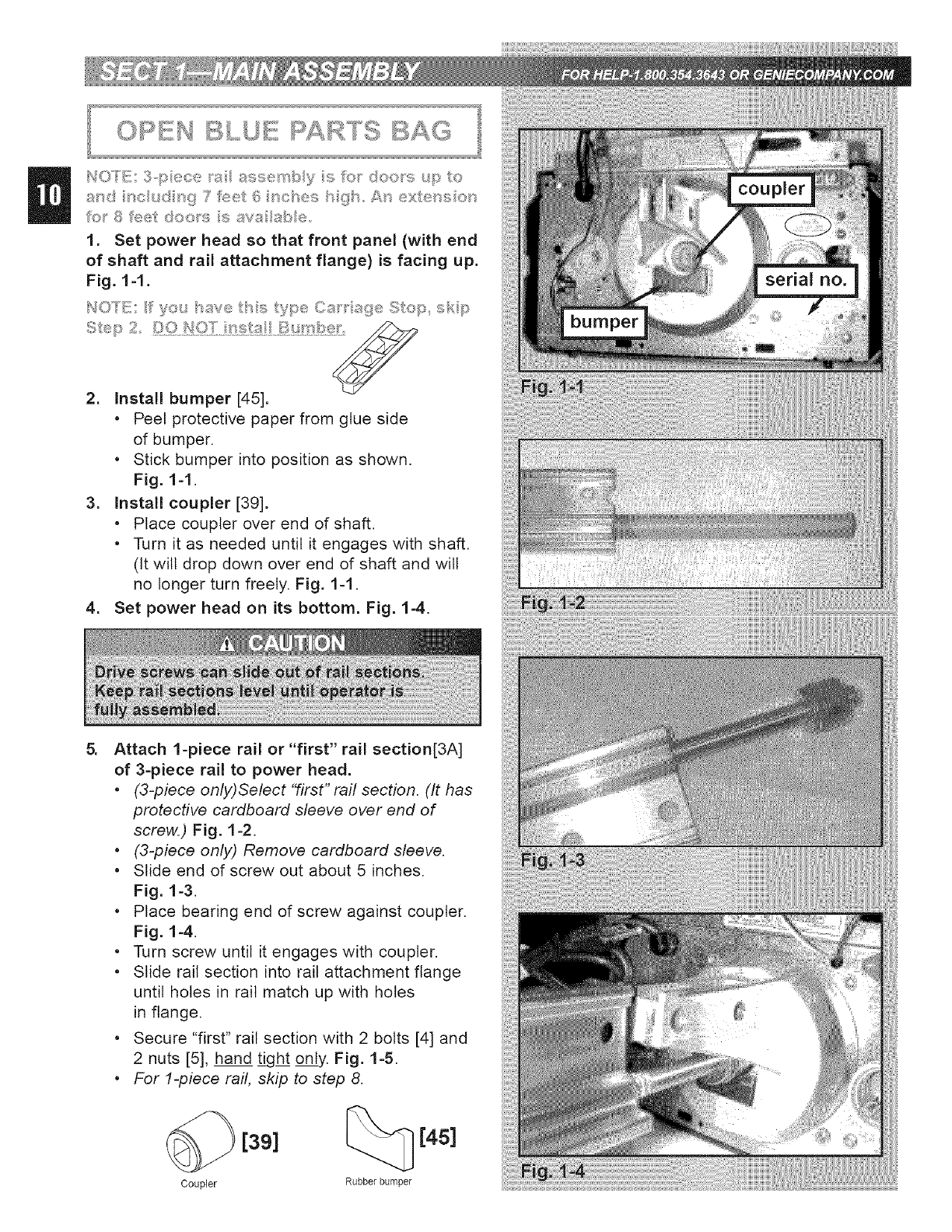
HO"I'E; 3,p ece ts assemby s Sc}__ doo_'s <p to
a/'_,d t_c_ d _g 7 f<i_ell6 _s@ses t}gt At_ ex/et_s et_
?o_'8?<:_et do®_'s says abe
1. Set power head so that front panel (with end
of shaft and rail attachment flange) is facing up.
Fig. 1-1.
I_O'TE: f yo_/_sve _/'t,s _y_:_e(it_w't _{_:_ Stop skp
tt,_p 2
2. Install bumper [45].
*Peel protective paper from glue side
of bumper.
*Stick bumper into position as shown.
Fig. 1-1.
3. Install coupler [39].
*Place coupler over end of shaft.
*Turn it as needed until it engages with shaft.
(it will drop down over end of shaft and will
no longer turn freely. Fig. 1-1.
4. Set power head on its bottom. Fig. 1-4.
Attach 1-piece rail or "first" rail section[3A]
of 3-piece rail to power head.
*(3-piece only)Select "first" raft section. (It has
protective cardboard sleeve over end of
screw.) Fig. 1-2.
*(3-piece only) Remove cardboard sleeve.
* Slide end of screw out about 5 inches.
Fig. 1-3.
* Place bearing end of screw against coupler.
Fig. 1-4.
* Turn screw until it engages with coupler.
* Slide rail section into rail attachment flange
until holes in rail match up with holes
in flange.
* Secure "first" rail section with 2 bolts [4] and
2 nuts [5], hand tight only. Fig. 1-5.
*For 1-piece rail, skip to step 8.
Coupler
[39] [4s]
Rubber bumper
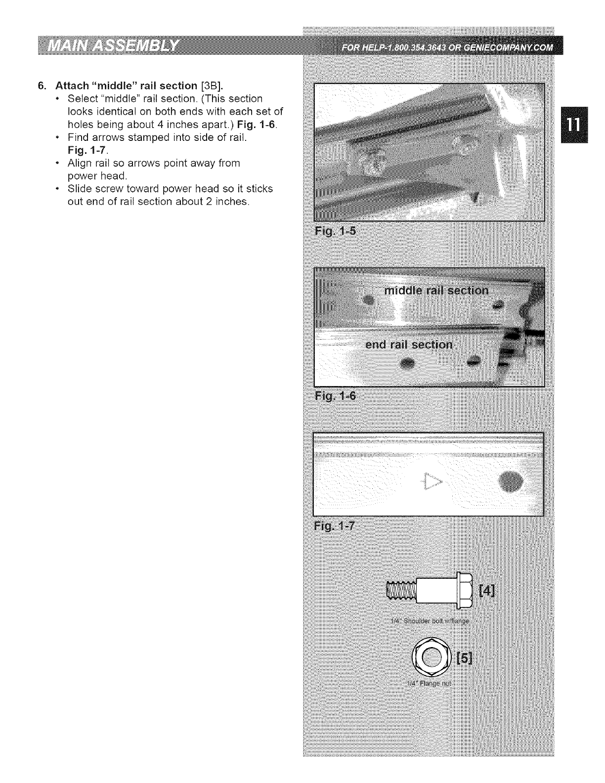
6_ Attach "middle" rail section [3B].
•Select "middle" rail section. (This section
books identical on both ends with each set of
holes being about 4 inches apart.) Fig. 1-6.
•Find arrows stamped into side of rail.
Fig. 1-7.
•Align rail so arrows point away from
power head.
•Slide screw toward power head so it sticks
out end of rail section about 2 inches.
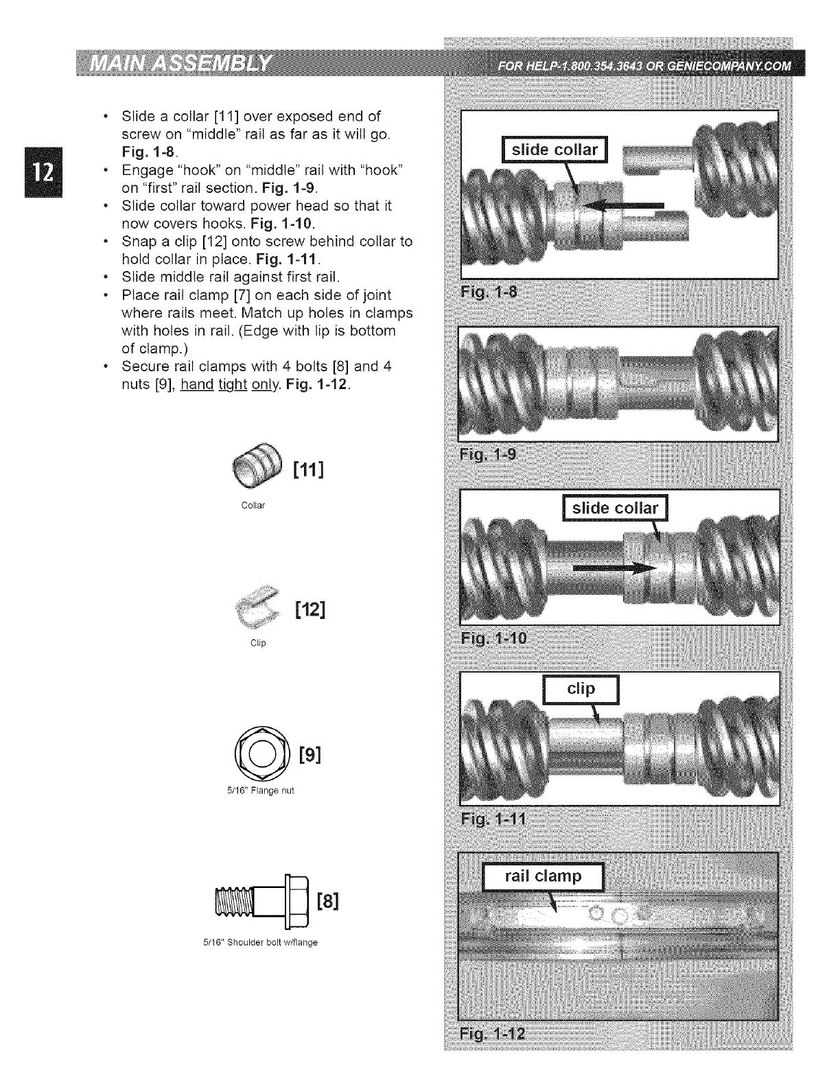
•Slide a collar [11] over exposed end of
screw on "middle" rail as far as it wilt go.
Fig. 1-8.
•Engage "hook" on "middle" rail with "hook"
on "first" rail section. Fig. 1-9.
•Slide collar toward power head so that it
now covers hooks. Fig. 1-10.
•Snap a clip [12] onto screw behind collar to
hold collar in place. Fig. 1-11.
•Slide middle rail against first rail.
•Place rail clamp [7] on each side of joint
where rails meet. Match up holes in clamps
with holes in rail. (Edge with lip is bottom
of clamp.)
•Secure rail clamps with 4 bolts [8] and 4
nuts [9], hand tight only. Fig. 1-12.
[12]
Clip
5/16" Flange nut
[8]
5/16" Shoulder bolt w/flange
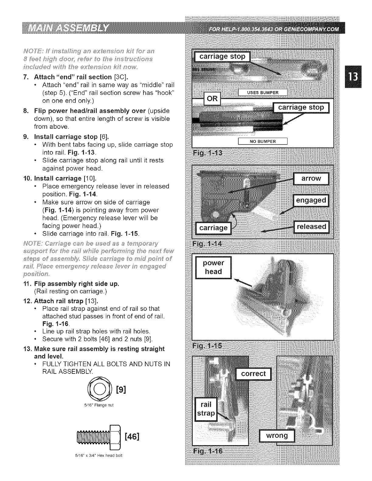
7. Attach "end" rail section [3C].
•Attach "end" rail in same way as "middle" rail
(step 5). ("End" rail section screw has "hook"
on one end only.)
8. Flip power head/rail assembly over (upside
down), so that entire length of screw is visible
from above.
9. install carriage stop [6].
• With bent tabs facing up, slide carriage stop
into rail. Fig. 1-13.
• Slide carriage stop along rail until it rests
against power head.
10. install carriage [10].
•Place emergency release lever in released
position. Fig. 1-14.
•Make sure arrow on side of carriage
(Fig. 1-14) is pointing away from power
head. (Emergency release lever wilt be
facing power head.)
•Slide carriage into rail. Fig. 1-15.
NOFi_iJ!/Oa_%Q:e oa,,',,be t_;'ed_s s _:_mp®p;s_/
_?#L £V#c.®®me;s[?®oc}f ;,'<#_t_ssehive;" M®g#g®d
11. Flip assembly right side up.
(Rail resting on carriage.)
12. Attach rail strap [13].
• Place rail strap against end of rail so that
attached stud passes in front of end of rail.
Fig. 1=16.
• Line up rail strap holes with rail holes.
• Secure with 2 bolts [46] and 2 nuts [9].
13. Make sure rail assembly is resting straight
and level.
• FULLY TIGHTEN ALL BOLTS AND NUTS IN
RAIL ASSEMBLY.
[91
5/16" Flange nut
[4S]
5/16" x 3/4" Hex head bolt
power
head
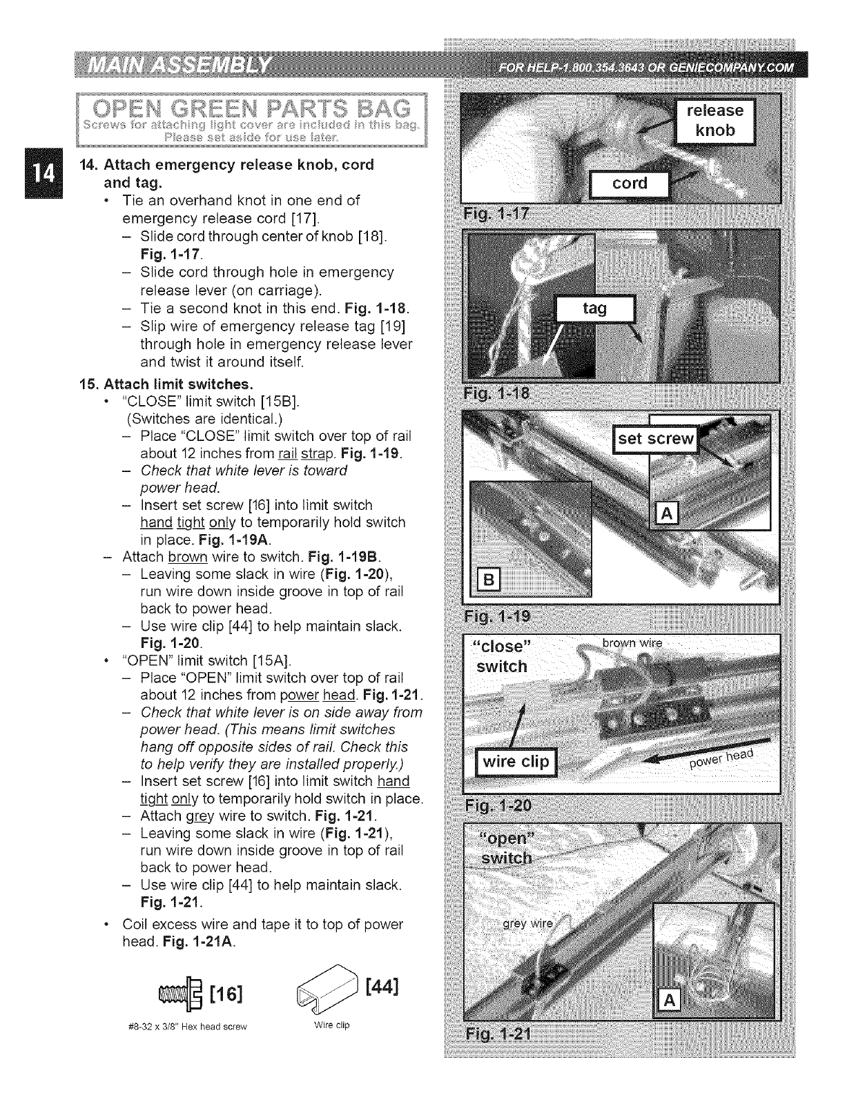
14. Attach emergency release knob, cord
and tag.
• Tie an overhand knot in one end of
emergency release cord [17].
- Slide cord through center of knob [18].
Fig. 1=17.
- Slide cord through hole in emergency
release lever (on carriage).
- Tie a second knot in this end. Fig. 1-18.
- Slip wire of emergency release tag [19]
through hole in emergency release lever
and twist it around itself.
15. Attach limit switches.
• "CLOSE" limit switch [15B].
(Switches are identical.)
- Place "CLOSE" limit switch over top of rail
about 12 inches from rail strap. Fig. 1-19.
-Check that white lever is toward
power head.
- Insert set screw [16] into limit switch
hand tight only to temporarily hold switch
in place. Fig. 1-19A.
- Attach brown wire to switch. Fig. 1-19B.
- Leaving some slack in wire (Fig. 1=20),
run wire down inside groove in top of rail
back to power head.
- Use wire clip [44] to help maintain slack.
Fig. 1=20.
"OPEN" limit switch [15A].
- Place "OPEN" limit switch over top of rail
about 12 inches from power head. Fig. 1=21.
-Check that white lever is on side away from
power head. (This means limit switches
hang off opposite sides of rail. Check this
to help verify they are installed properly.)
- Insert set screw [16] into limit switch hand
tight only to temporarily hold switch in place.
- Attach grey wire to switch. Fig. 1=21.
- Leaving some slack in wire (Fig. 1=21),
run wire down inside groove in top of rail
back to power head.
- Use wire clip [44] to help maintain slack.
Fig. 1-21.
Coil excess wire and tape it to top of power
head. Fig. 1-21A.
[16] [44]
#8-32 x 3/8" Hex head screw Wire clip
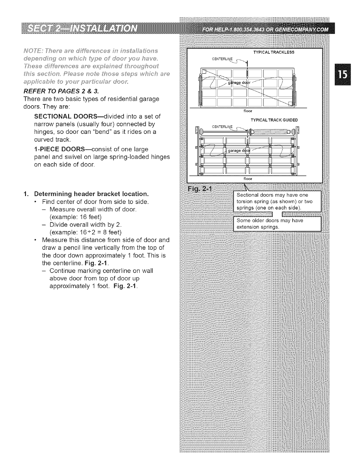
3"h®s® dJ_e?-enc®s a_'e _?t:_ Mn®d h_oudh®u
thh,_ sec ® Pk_ase noh_:__'hose ste_:¢s whFch a?-e
app icabF_ to .yo_,_-pa2'dcuF@2'd<:_oJ",
REFER TO PAGES 2 & 3.
There are two basic types of residential garage
doors. They are:
SECTIONAL DOORS--divided into a set of
narrow panels (usually four) connected by
hinges, so door can "bend" as it rides on a
curved track.
1-PIECE DOORS--consist of one barge
panel and swivel on large spring-loaded hinges
on each side of door.
Determining header bracket location.
• Find center of door from side to side.
- Measure overall width of door.
(example: 16 feet)
- Divide overall width by 2.
(example: 16+2 = 8 feet)
• Measure this distance from side of door and
draw a pencil line vertically from the top of
the door down approximately 1 foot. This is
the centerline. Fig. 2-1.
- Continue marking centerline on wall
above door from top of door up
approximately 1 foot. Fig. 2-1.
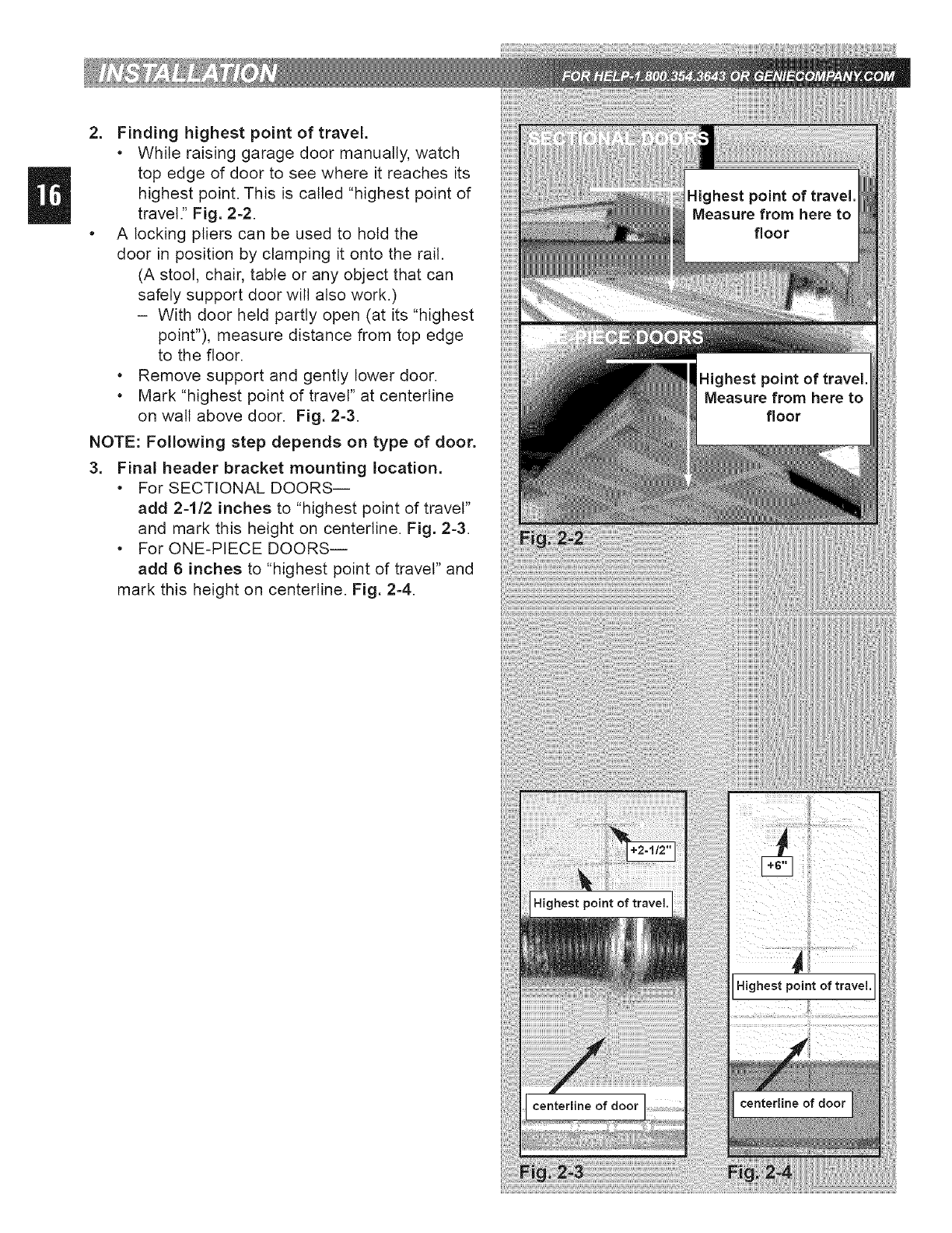
2. Finding highest point of travel.
• Whileraisinggaragedoor manually,watch
top edge of door to see where it reaches its
highest point. This is called "highest point of
travel." Fig. 2-2.
•A locking pliers can be used to hold the
door in position by clamping it onto the rail.
(A stool, chair, table or any object that can
safely support door will also work.)
- With door held partly open (at its "highest
point"), measure distance from top edge
to the floor.
• Remove support and gently bower door.
• Mark "highest point of travel" at centerline
on watt above door. Fig. 2-3.
NOTE: Following step depends on type of door.
3. Final header bracket mounting location.
• For SECTIONAL DOORS--
add 2-1/2 inches to "highest point of travel"
and mark this height on centerline. Fig. 2-3.
• For ONE-PIECE DOORS--
add 6 inches to "highest point of travel" and
mark this height on centerline. Fig. 2-4.
F,,. 11 @
( C_I OF s+,s. ;_ ........ @,,y s ,; o
_f@©/- ss #s
££ ....
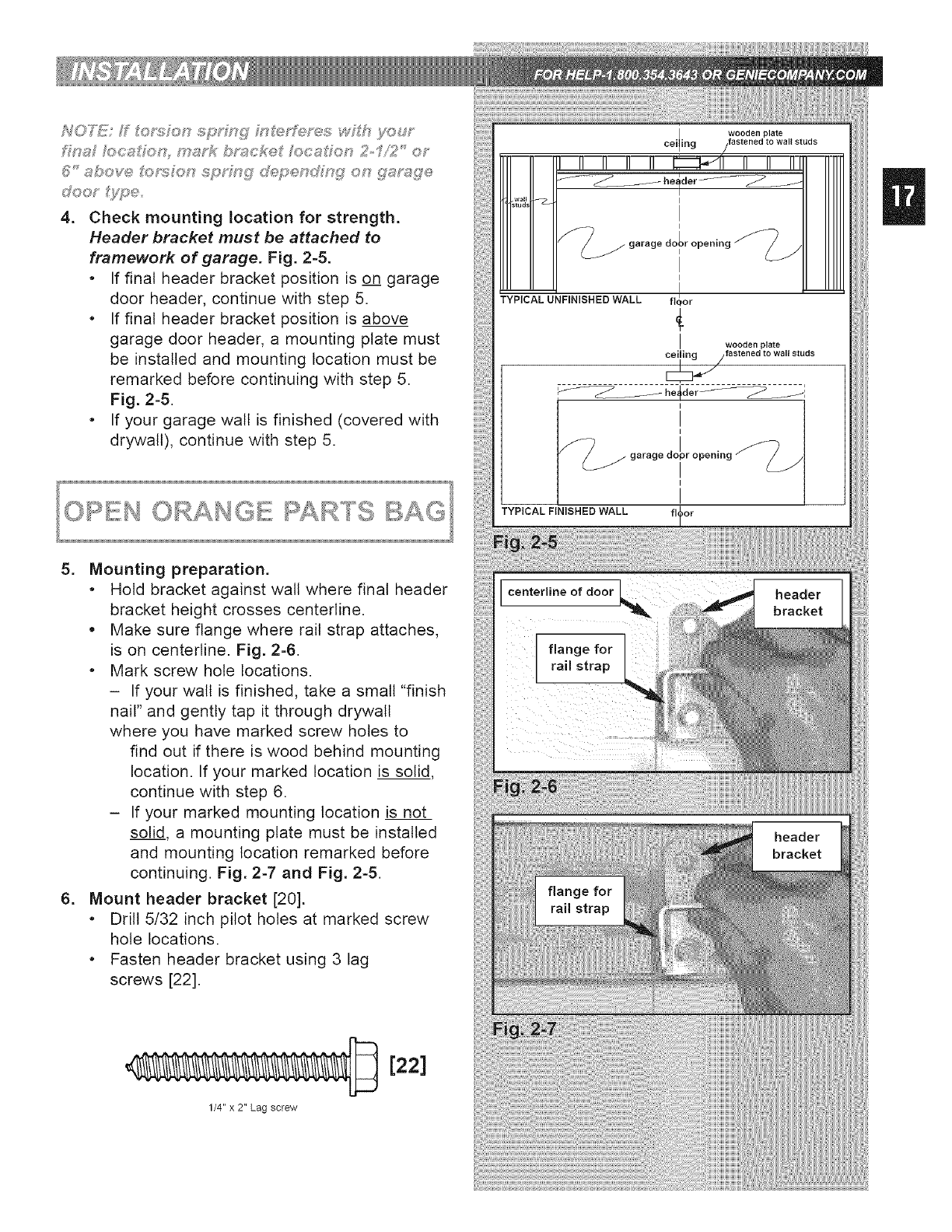
4. Check mounting location for strength.
Header bracket must be attached to
framework of garage. Fig. 2-5.
• If final header bracket position is on garage
door header, continue with step 5.
• If final header bracket position is above
garage door header, a mounting plate must
be installed and mounting location must be
remarked before continuing with step 5.
Fig. 2-5.
•If your garage wall is finished (covered with
drywall), continue with step 5.
TYPICAL FINISHED WALL
5. Mounting preparation.
• Hold bracket against wall where final header
bracket height crosses centerline.
• Make sure flange where rail strap attaches,
is on centerline. Fig. 2-6.
• Mark screw hole locations.
- If your walt is finished, take a small "finish
nail" and gently tap it through drywall
where you have marked screw holes to
find out if there is wood behind mounting
location. If your marked location is solid,
continue with step 6.
- If your marked mounting location is not
solid, a mounting plate must be installed
and mounting location remarked before
continuing. Fig. 2-7 and Fig. 2-5.
6. Mount header bracket [20].
• Drill 5/32 inch pilot holes at marked screw
hole locations.
• Fasten header bracket using 3 lag
screws [22].
1/4" x 2" Lag screw
[22]
flange for
rail strap
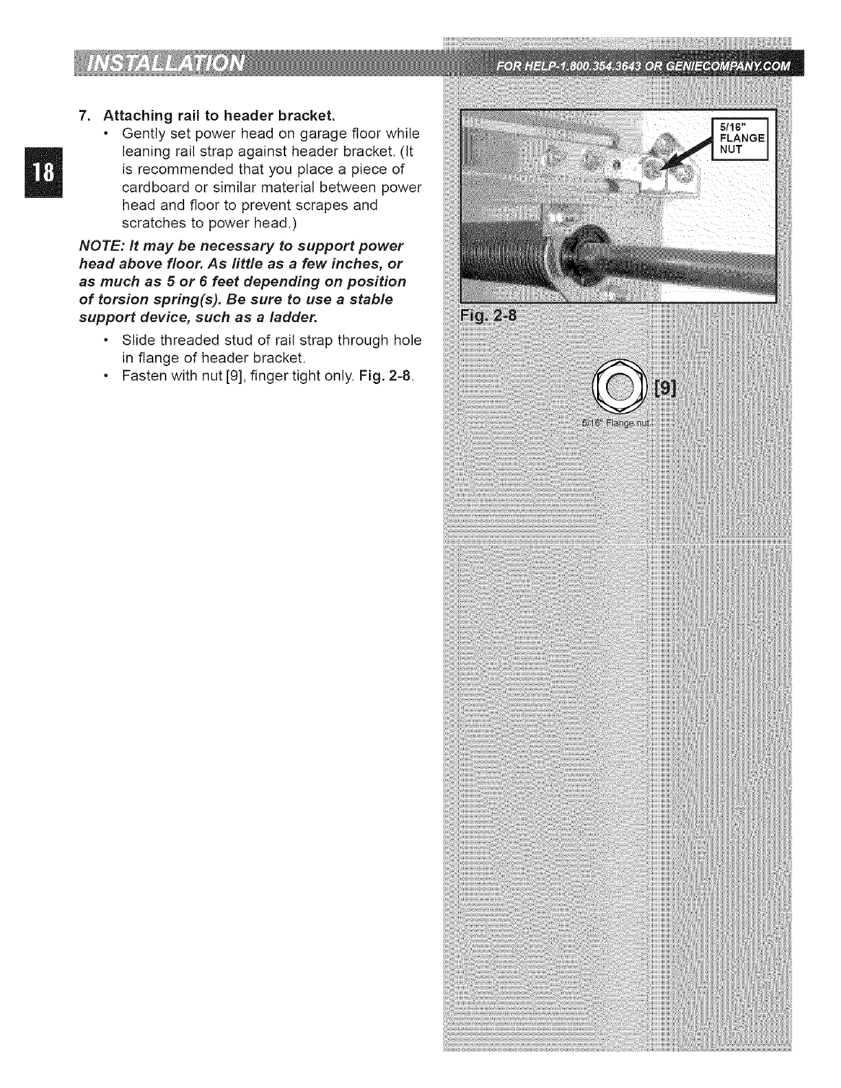
7. Attaching rail to header bracket.
•Gently set power head on garage floor while
leaning rail strap against header bracket. (It
is recommended that you place a piece of
cardboard or similar material between power
head and floor to prevent scrapes and
scratches to power head.)
NOTE: It may be necessary to support power
head above floor. As little as a few inches, or
as much as 5 or 6 feet depending on position
of torsion spring(s). Be sure to use a stable
support device, such as a ladder.
•Slide threaded stud of rail strap through hole
in flange of header bracket.
•Fasten with nut [9], finger tight only. Fig. 2-8.
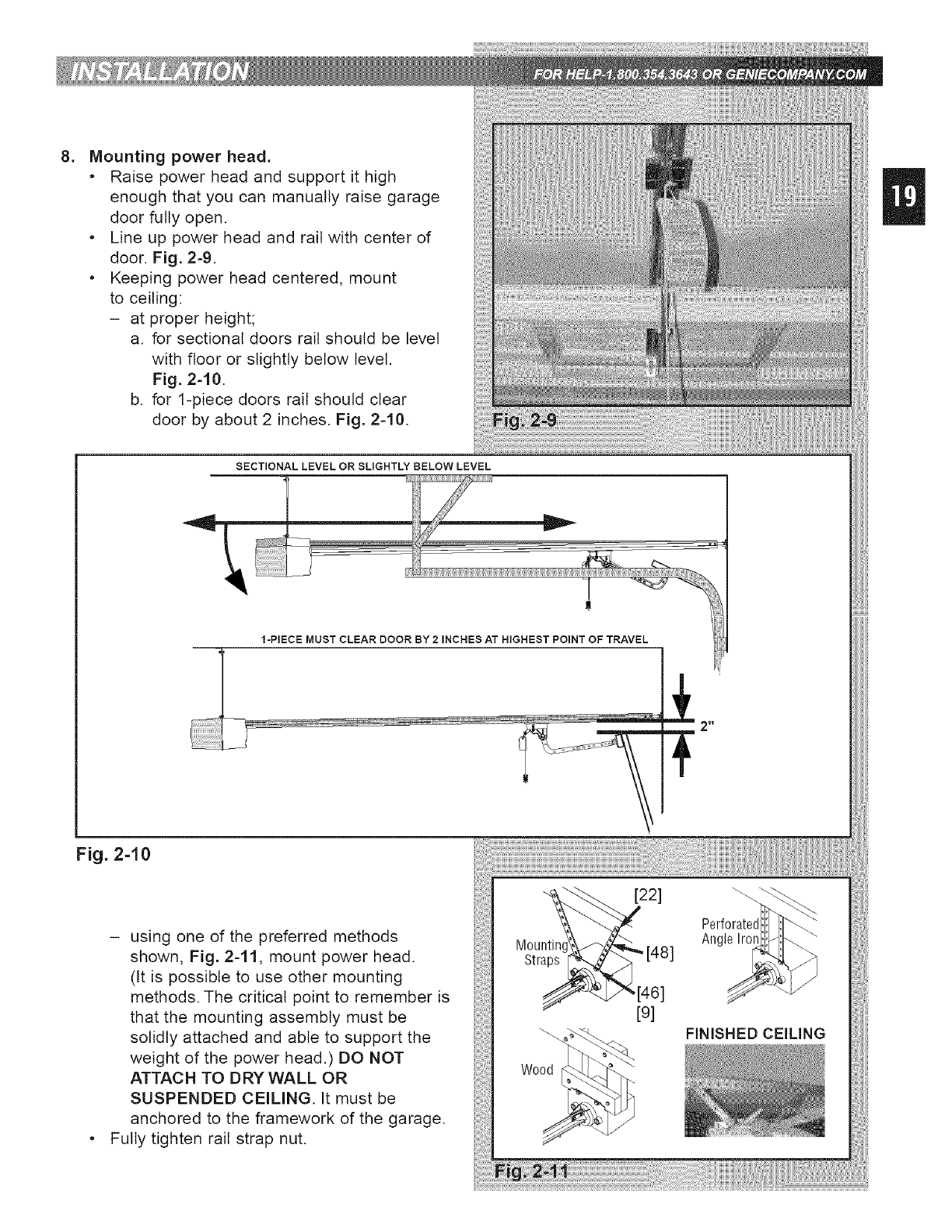
.Mounting power head.
•Raise power head and support it high
enough that you can manually raise garage
door fully open.
•Line up power head and rail with center of
door. Fig. 2-9.
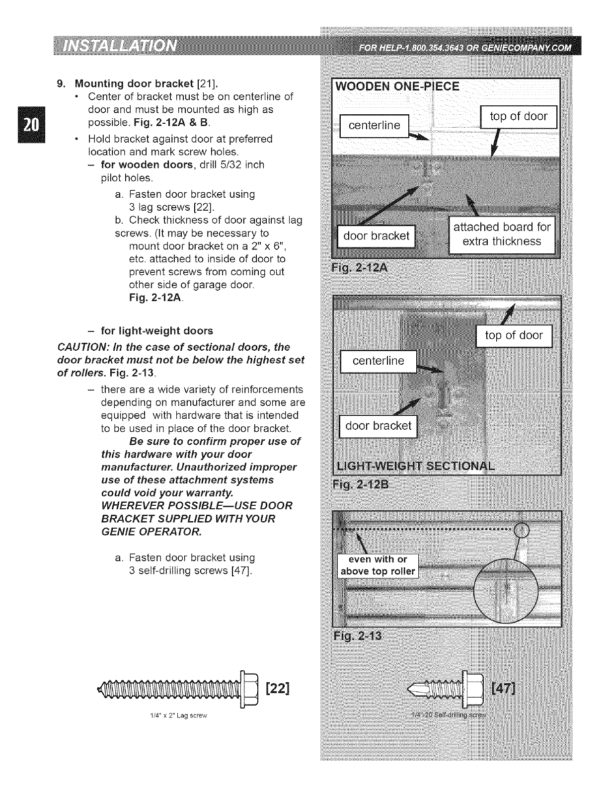
•Keeping power head centered, mount
to ceiling:
- at proper height;
a. for sectional doors rail should be level
with floor or slightly below level.
Fig. 2-10.
b. for 1-piece doors rail should clear
door by about 2 inches. Fig. 2-10.
SECTIONAL LEVEL OR SLIGHTLY BELOW LEVEL
1-PIECE MUST CLEAR DOOR BY 2 INCHES AT HIGHEST POINT OF TRAVEL
2 II
Fig. 2-10
- using one of the preferred methods
shown, Fig. 241, mount power head.
fit is possible to use other mounting
methods. The critical point to remember is
that the mounting assembly must be
solidly attached and able to support the
weight of the power head.) DO NOT
ATTACH TO DRY WALL OR
SUSPENDED CEILING. It must be
anchored to the framework of the garage.
Fully tighten rail strap nut.
Wood
Anc
FINISHED CEILING
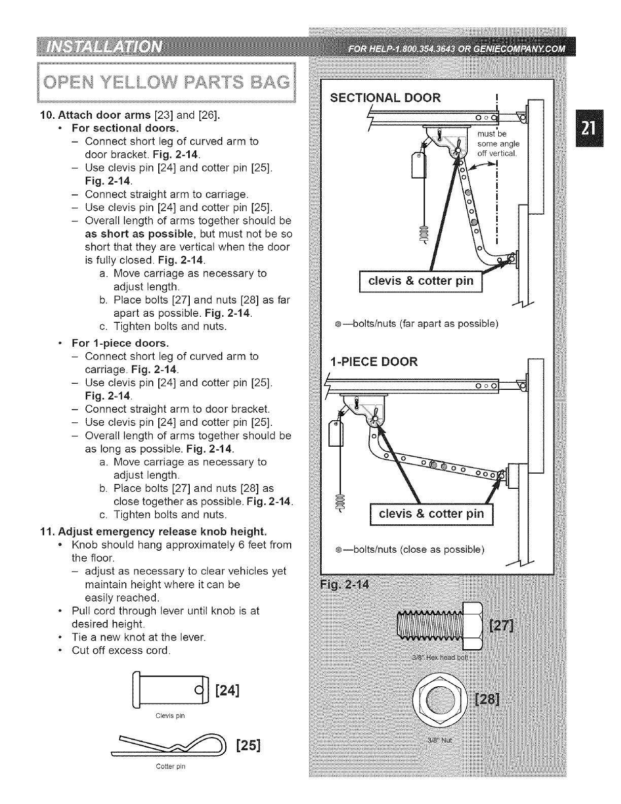
9_ Mounting door bracket [21].
•Center of bracket must be on centerline of
door and must be mounted as high as
possible. Fig. 2-12A & B.
•Hold bracket against door at preferred
location and mark screw holes.
- for wooden doors, drill 5/32 inch
pilot holes.
a. Fasten door bracket using
3 lag screws [22].
b. Check thickness of door against lag
screws. (It may be necessary to
mount door bracket on a 2" x 6",
etc. attached to inside of door to
prevent screws from coming out
other side of garage door.
Fig. 2-12A.
- for light=weight doors
CAUTION: In the case of sectional doors, the
door bracket must not be below the highest set
of rollers. Fig. 2-13.
- there are a wide variety of reinforcements
depending on manufacturer and some are
equipped with hardware that is intended
to be used in place of the door bracket.
Be sure to confirm proper use of
this hardware with your door
manufacturer. Unauthorized improper
use of these attachment systems
could void your warranty.
WHEREVER POSSIBLE--USE DOOR
BRACKET SUPPLIED WITH YOUR
GENIE OPERATOR.
a. Fasten door bracket using
3 self-drilling screws [47].
1/4" x 2" Lag screw
[22]
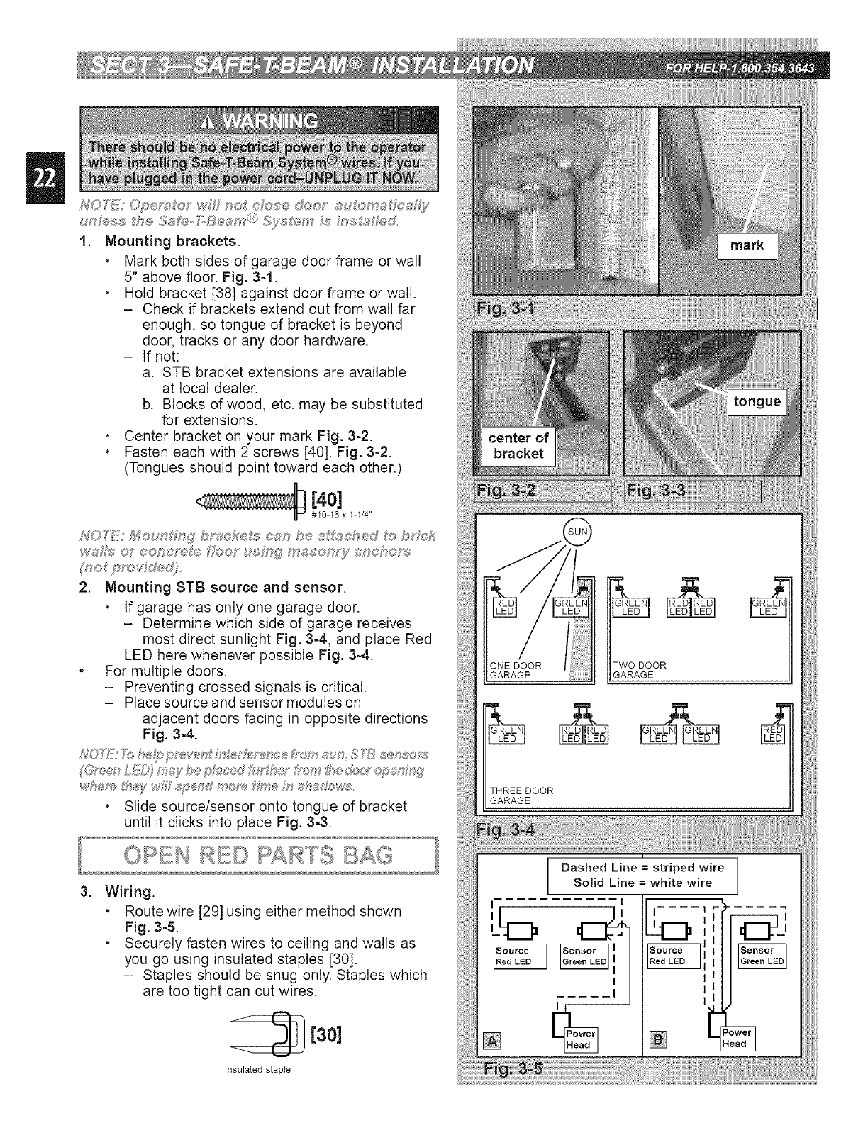
10. Attach door arms [23] and [26].
• For sectional doors.
- Connect short leg of curved arm to
door bracket. Fig. 244.
- Use clevis pin [24] and cotter pin [25].
Fig. 2-14.
- Connect straight arm to carriage.
- Use clevis pin [24] and cotter pin [25].
- Overall length of arms together should be
as short as possible, but must not be so
short that they are vertical when the door
is fully closed. Fig. 2-14.
a. Move carriage as necessary to
adjust length.
b. Place bolts [27] and nuts [28] as far
apart as possible. Fig. 2-14.
c. Tighten bolts and nuts.
• For 1-piece doors.
- Connect short leg of curved arm to
carriage. Fig. 2-14.
- Use clevis pin [24] and cotter pin [25].
Fig. 2-14.
- Connect straight arm to door bracket.
- Use clevis pin [24] and cotter pin [25].
- Overall length of arms together should be
as long as possible. Fig. 2-14.
a. Move carriage as necessary to
adjust length.
b. Place bolts [27] and nuts [28] as
close together as possible. Fig. 2-14.
c. Tighten bolts and nuts.
11. Adjust emergency release knob height.
, Knob should hang approximately 6 feet from
the floor.
- adjust as necessary to clear vehicles yet
maintain height where it can be
easily reached.
• Pull cord through lever until knob is at
desired height.
• Tie a new knot at the lever.
• Cut off excess cord.
c[] [24]
Clevis pin
, [2s]
Cotter pin
SECTIONAL DOOR
/
?
I
must be I I
:ffmi angle I I
clevis & cotter pin
@--bolts/nuts (far apart as possible)
1-PIECE DOOR
i clevis & cotter pin
@--bolts/nuts (close as possible)
1. Mounting brackets.
, Mark both sides of garage door frame or wall
5" above floor. Fig. 3=1.
, Hold bracket [38] against door frame or wall.
- Check if brackets extend out from wall far
enough, so tongue of bracket is beyond
door, tracks or any door hardware.
- If not:
a. STB bracket extensions are available
at local dealer.
b. Blocks of wood, etc. may be substituted
for extensions.
. Center bracket on your mark Fig. 3=2.
, Fasten each with 2 screws [40]. Fig. 3=2.
(Tongues should point toward each other.)
[4o]
#10-16 x 1-1/4"
2. Mounting STB source and sensor.
,If garage has only one garage door.
- Determine which side of garage receives
most direct sunlight Fig. 3=4, and place Red
LED here whenever possible Fig. 3-4.
. For multiple doors.
- Preventing crossed signals is critical.
- Place source and sensor modules on
adjacent doors facing in opposite directions
Fig. 3-4.
•Slide source/sensor onto tongue of bracket
until it clicks into place Fig. 3-3.
TWO DOOR
GARAGEGARAGE
THREE DOOR
GARAGE
=Wiring.
,Route wire [29] using either method shown
Fig. 3-5.
,Securely fasten wires to ceiling and walls as
you go using insulated staples [30].
- Staples should be snug only. Staples which
are too tight can cut wires.
[30]
Insulated staple
L
Dashed Line =striped wire
Solid Line = white wire
I I I
[]
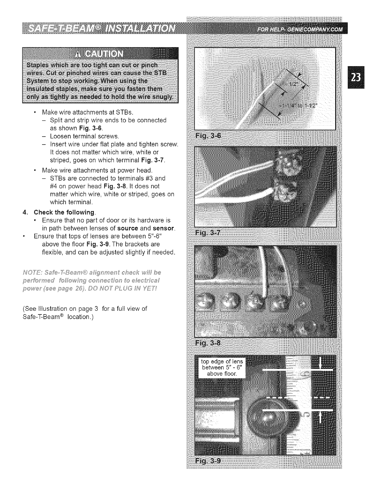
, Make wire attachments at STBs.
- Split and strip wire ends to be connected
as shown Fig. 3-6.
- Loosen terminal screws.
- Insert wire under flat plate and tighten screw.
It does not matter which wire, white or
striped, goes on which terminal Fig. 3-7.
, Make wire attachments at power head.
- STBs are connected to terminals #3 and
#4 on power head Fig. 3-8. tt does not
matter which wire, white or striped, goes on
which terminal.
4. Check the following.
, Ensure that no part of door or its hardware is
in path between lenses of source and sensor.
, Ensure that tops of lenses are between 5"-6"
above the floor Fig. 3=9. The brackets are
flexible, and can be adjusted slightly if needed.
(See Illustration on page 3 for a full view of
Safe-T-Beam ® location.)
1. Run wire from power head to wall control
, Find location for wall control:
- In sight of door and away from moving parts.
- At least 5 feet from floor, so small
children cannot reach it.
• Route wire from wall control to power head.
• Use staples to fasten wire to ceiling and wall.
NON_!: Use only _J;_p e_; nc uded
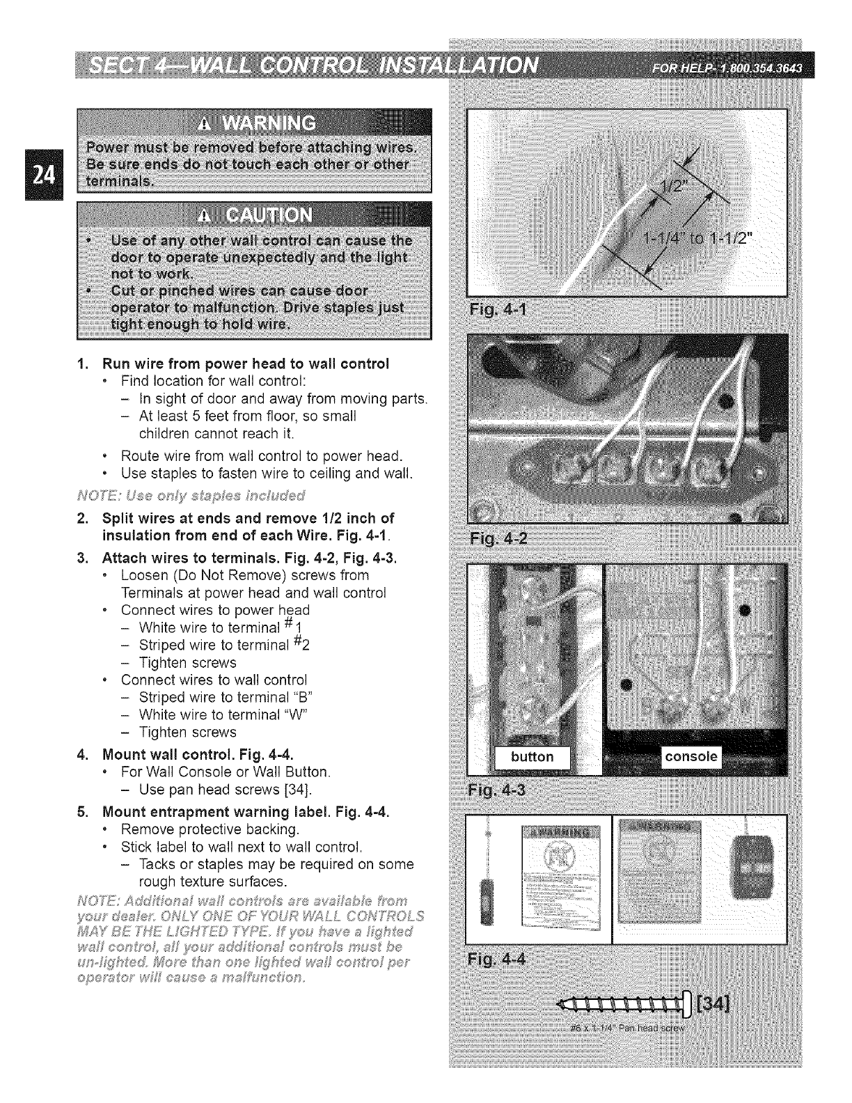
2. Split wires at ends and remove 1!2 inch of
insulation from end of each Wire. Fig. 4=1.
3. Attach wires to terminals. Fig. 4=2, Fig. 4=3.
,Loosen (Do Not Remove) screws from
Terminals at power head and wall control
• Connect wires to power head
- White wire to terminal # 1
- Striped wire to terminal #2
- Tighten screws
• Connect wires to wall control
- Striped wire to terminal "B"
- White wire to terminal "W"
- Tighten screws
4. Mount wall control. Fig. 44.
.For Wall Console or Wall Button.
- Use pan head screws [34].
5. Mount entrapment warning label. Fig. 44.
.Remove protective backing.
• Stick label to wall next to wall control.
- Tacks or staples may be required on some
rough texture surfaces.
f<:,:y d®aFef' ONLY ONE OF YOUR _LL CON'f\POLS
_;_Y BE THE L GH'_) T'_'_E. f _m,_have aZ_h%_d
ws eet_f/_oh s :y'_:,:r add _;_'®t:_af¢ot:_g'oJs m_; be
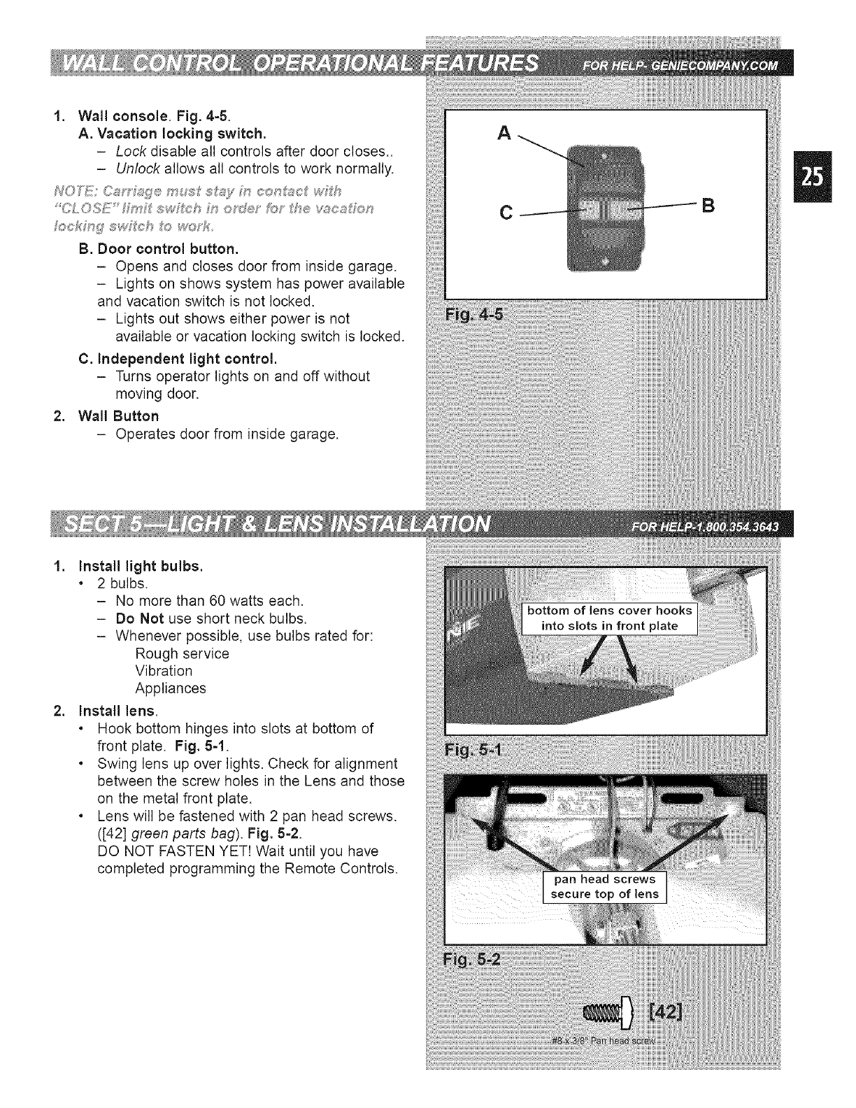
1. Wall console. Fig. 4-5.
A. Vacation locking switch.
-Lock disable all controls after door closes..
-Unlock allows all controls to work normally.
fockMg" swf_eh t_:_woTf_
B. Door control button.
- Opens and closes door from inside garage.
- Lights on shows system has power available
and vacation switch is not locked.
- Lights out shows either power is not
available or vacation locking switch is locked.
C. independent light control.
- Turns operator lights on and off without
moving door.
2. Wall Button
- Operates door from inside garage.
A
CB
.
.
Install light bulbs.
. 2 bulbs.
- No more than 60 watts each.
-Do Not use short neck bulbs.
- Whenever possible, use bulbs rated for:
Rough service
Vibration
Appliances
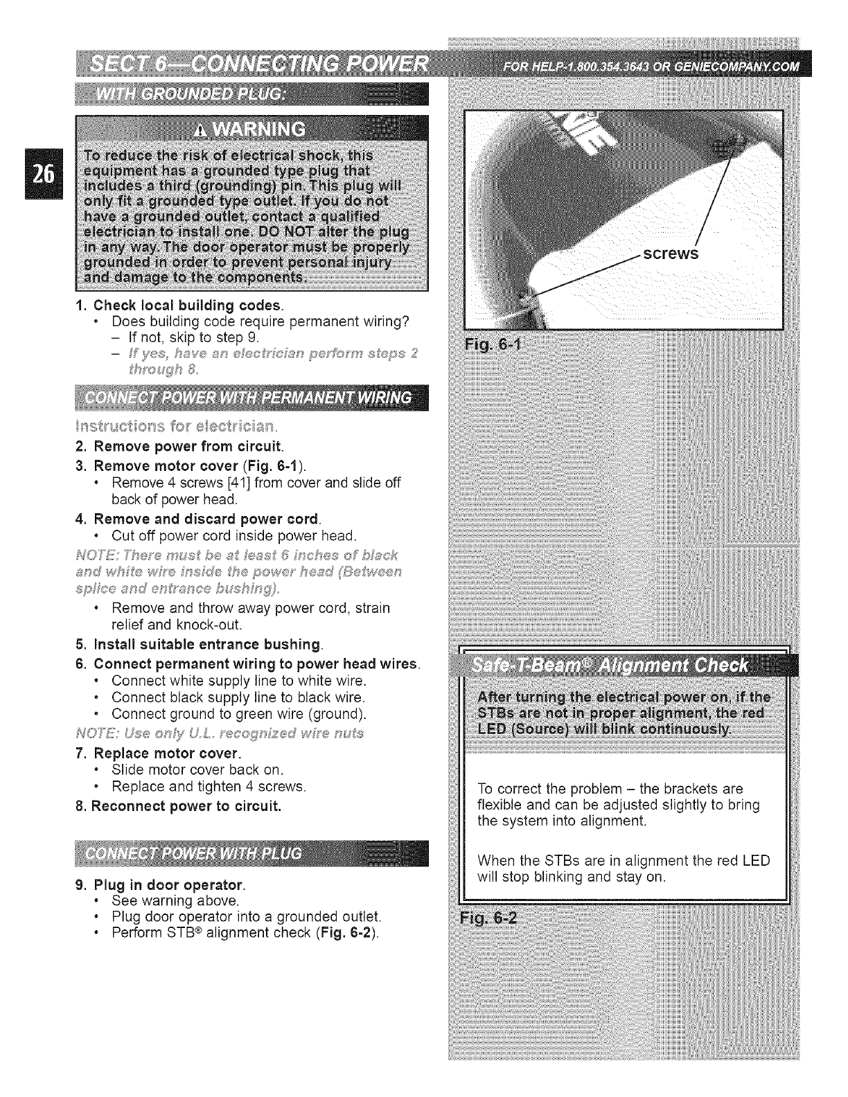
Install lens.
. Hook bottom hinges into slots at bottom of
front plate. Fig. 5=1.
. Swing lens up over lights. Check for alignment
between the screw holes in the Lens and those
on the metal front plate.
. Lens will be fastened with 2 pan head screws.
([42] green parts bag). Fig. 5-2.
DO NOT FASTEN YET! Wait until you have
completed programming the Remote Controls.
1. Check local building codes.
* Does building code require permanent wiring?
- If not, skip to step 9.
2. Remove power from circuit.
3. Remove motor cover (Fig. 64).
.Remove 4 screws [41] from cover and slide off
back of power head.
4. Remove and discard power cord.
.Cut off power cord inside power head.
. Remove and throw away power cord, strain
relief and knock-out.
5. Install suitable entrance bushing.
6. Connect permanent wiring to power head wires.
. Connect white supply line to white wire.
• Connect black supply line to black wire.
• Connect ground to green wire (ground).
NO_!!! U\se ®n_;/ U L_ ecoqn?_;,d wh-e nuJ_;
7. Replace motor cover.
. Slide motor cover back on.
•Replace and tighten 4 screws.
8. Reconnect power to circuit.
9. Plug in door operator.
. See warning above.
. Plug door operator into a grounded outlet.
. Perform STB ®alignment check (Fig. 6-2).
To correct the problem - the brackets are
flexible and can be adjusted slightly to bring
the system into alignment.
When the STBs are in alignment the red LED
will stop blinking and stay on.
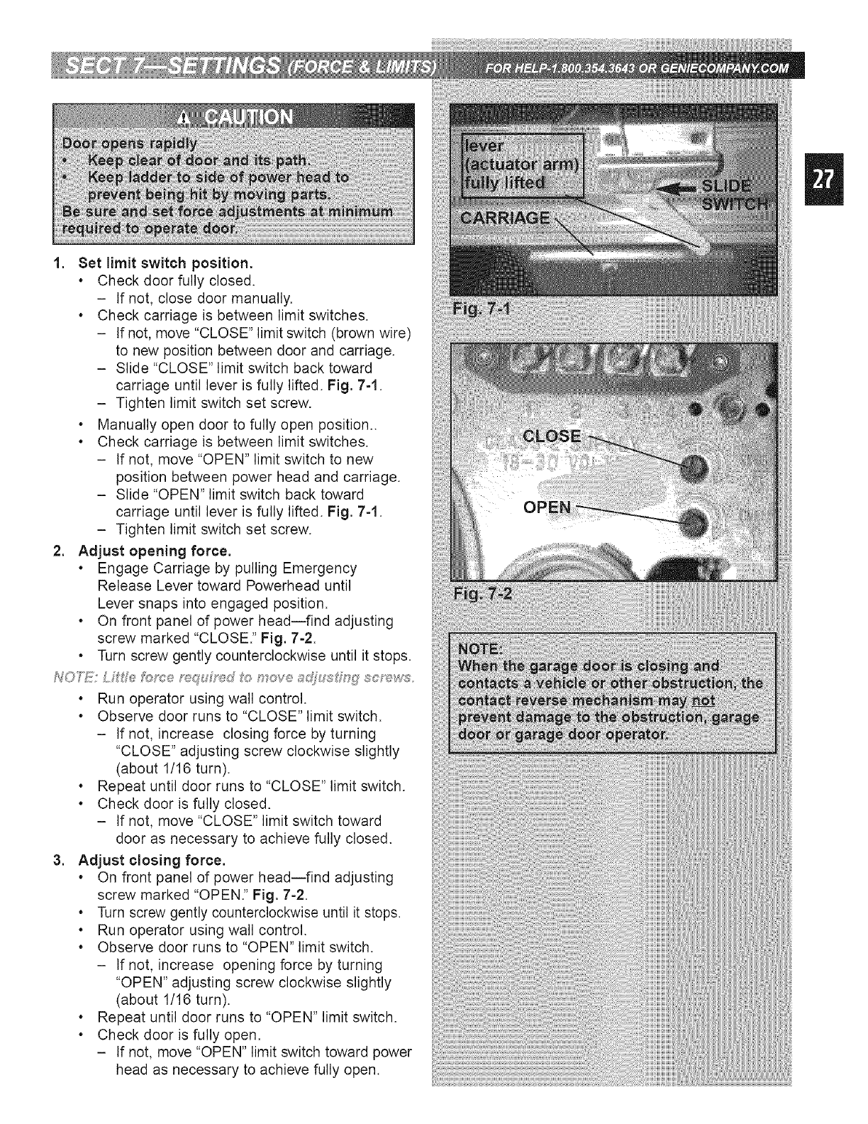
1. Set limit switch position.
,Check door fully closed.
- tf not, close door manually.
,Check carriage is between limit switches.
- If not, move "CLOSE" limit switch (brown wire)
to new position between door and carriage.
- Slide "CLOSE" limit switch back toward
carriage until lever is fully lifted. Fig. 7-1.
- Tighten limit switch set screw.
,Manually open door to fully open position..
,Check carriage is between limit switches.
- If not, move "OPEN" limit switch to new
position between power head and carriage.
- Slide "OPEN" limit switch back toward
carriage until lever is fully lifted. Fig. 7-1.
- Tighten limit switch set screw.
2. Adjust opening force.
, Engage Carriage by pulling Emergency
Release Lever toward Powerhead until
Lever snaps into engaged position.
, On front panel of power head--find adjusting
screw marked "CLOSE." Fig. 7-2.
•Turn screw gently counterclockwise until it stops.
. Run operator using wall control.
. Observe door runs to "CLOSE" limit switch.
- If not, increase closing force by turning
"CLOSE" adjusting screw clockwise slightly
(about 1/16 turn).
,Repeat until door runs to "CLOSE" limit switch.
,Check door is fully closed.
- If not, move "CLOSE" limit switch toward
door as necessary to achieve fully closed.
3. Adjust closing force.
,On front panel of power head--find adjusting
screw marked "OPEN." Fig. 7=2.
,Turn screw gently counterclockwise until it stops.
,Run operator using wall control.
,Observe door runs to "OPEN" limit switch.
- If not, increase opening force by turning
"OPEN" adjusting screw clockwise slightly
(about 1/16 turn).
,Repeat until door runs to "OPEN" limit switch.
,Check door is fully open.
- If not, move "OPEN" limit switch toward power
head as necessary to achieve fully open.
Limit switch adjustments must be completed
before running contact reverse test.
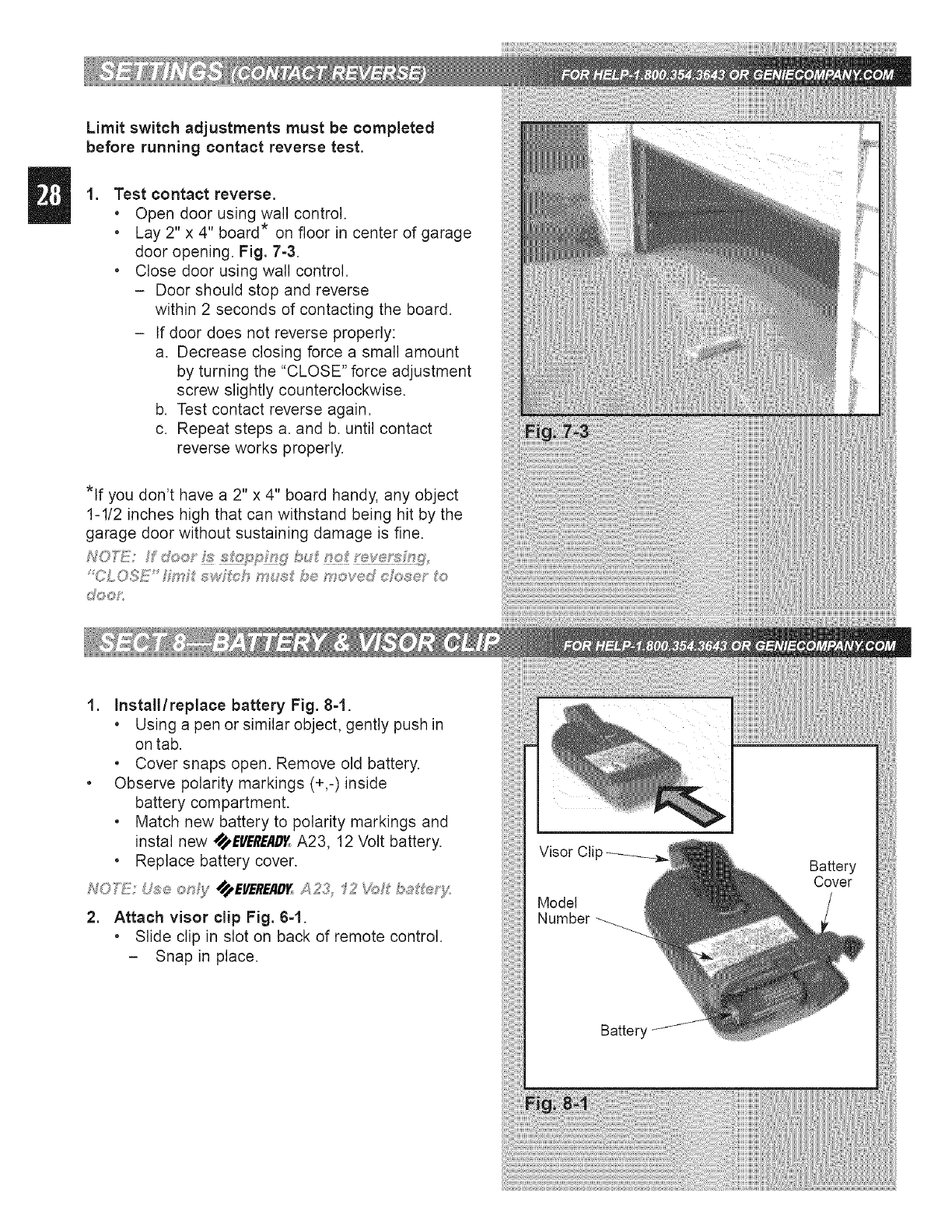
,Test contact reverse.
. Open door using wall control.
. Lay 2" x 4" board* on floor in center of garage
door opening. Fig. 7-3.
. Close door using wall control.
- Door should stop and reverse
within 2 seconds of contacting the board.
- If door does not reverse properly:
a. Decrease closing force a small amount
by turning the "CLOSE" force adjustment
screw slightly counterclockwise.
b. Test contact reverse again.
c. Repeat steps a. and b. until contact
reverse works properly.
*If you don't have a 2" x 4" board handy, any object
1-1/2 inches high that can withstand being hit by the
garage door without sustaining damage is fine.
NOD!:!!: do_:y _ _!_:_?P_::_WX7bu_ _t_;__;t f_;W
'CLOSE _4_ _,_wfch mu_ be mov®d c_2_e' o
d%_oP:
1. Install/replace battery Fig. 8-1.
. Using a pen or similar object, gently push in
on tab.
. Cover snaps open. Remove old battery.
. Observe polarity markings (+,-)inside
battery compartment.
. Match new battery to polarity markings and
instal new SS_,EVEREAD_A23, 12 Volt battery.
• Replace battery cover.
2. Attach visor clip Fig. 6-1.
.Slide clip in slot on back of remote control.
- Snap in place.
NOi"£_; £')Jc _et'_o_'edevce mus_ k_e
p_o_7 4s,mme_:Fse;_4s,sf#/e,y
h,!O_]]!_;Remo_e co '9"oFs w_'_e cos_, dec F
NO _#,]f: WG_e_puogms_ mm8 _emog,!:;c@'s_,!'e,;, must
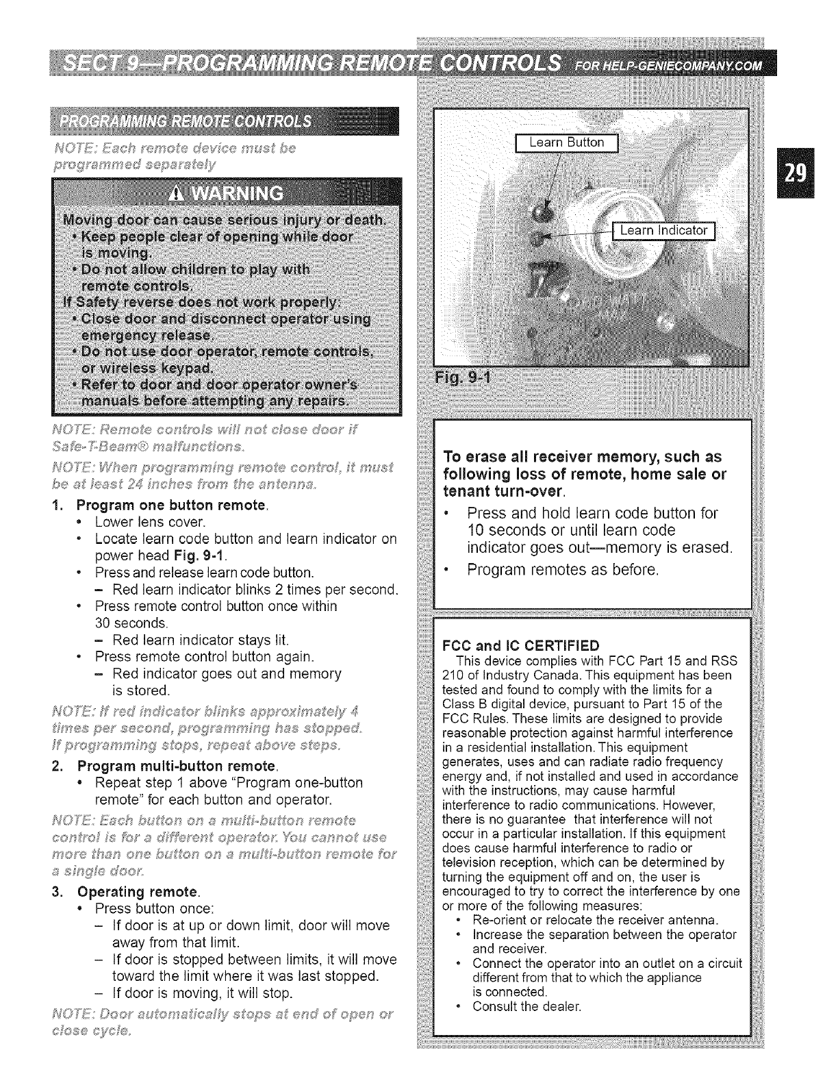
1. Program one button remote.
• Lower lens cover.
.Locate learn code button and learn indicator on
power head Fig. 9-1.
• Press and release learn code button.
-Red learn indicator blinks 2 times per second.
• Press remote control button once within
30 seconds.
-Red learn indicator stays lit.
• Press remote control button again.
- Red indicator goes out and memory
is stored.
des per seeor:_d, p_ogx_;mmm£ ha s_o_p_ed,
2. Program multi-button remote.
= Repeat step 1 above "Program one-button
remote" for each button and operator.
sf_sFngFe does
3. Operating remote.
• Press button once:
- If door is at up or down limit, door will move
away from that limit.
- If door is stopped between limits, it will move
toward the limit where it was last stopped.
- tf door is moving, it will stop.
e/ose e}_;_;/#:,_,
Learn Indicator
To erase all receiver memory, such as
following loss of remote, home sale or
tenant turn=over
• Press and hold learn code button for
10 seconds or until learn code
indicator goes out--memory is erased.
• Program remotes as before.
FCC and IC CERTIFIED
This device complies with FCC Part 15 and RSS
210 of Industry Canada. This equipment has been
tested and found to comply with the limits for a
Class B digital device, pursuant to Part 15 of the
FCC Rules. These limits are designed to provide
reasonable protection against harmful interference
in a residential installation. This equipment
generates, uses and can radiate radio frequency
energy and, if not installed and used in accordance
with the instructions, may cause harmful
interference to radio communications. However,
there is no guarantee that interference will not
occur in a particular installation. If this equipment
does cause harmful interference to radio or
television reception, which can be determined by
turning the equipment off and on, the user is
encouraged to try to correct the interference by one
or more of the following measures:
• Re-orient or relocate the receiver antenna.
• Increase the separation between the operator
and receiver.
• Connect the operator into an outlet on a circuit
different from that to which the appliance
is connected.
• Consult the dealer.
Transmitters comply with all United States and Canadian legal
requirements as of the date of manufacture. No warranty is
made that they comply with all legal requirements of any other
jurisdiction. If transmitters are to be used in another country,
the importer must determine compliance with any local laws
and regulations which may differ from United States and
Canadian requirements prior to use.
Los transmisores cumplen con todas tas reglamentaciones
legales de los Estados Unidos y del Canad, en la fecha de
fabricaci n. Ninguna garant a se da que cumplan con todas las
reglamentaciones legates de ninguna otra jurisdicd n. Si los
transmisores se van a utilizar en otro pa s, el importador debe
determinar si cumplen con las reglamentaciones y leyes
locales que puedan ser diferentes alas reglamentadones
de los Estados Unidos y del Canad, antes de usar los mismos.
Les metteurs sent conformes la r glementation am ricaine
et canadienne compter de leur date de fabrication. Aucune
garantie nest stipule indiquant qu ils sent conformes toutes
les prescriptions juridiques d autres autodt s. Si les metteurs
sont utiNs s dans d autres pays, il incombe I importateur d en
d terminer leur conformit aux lois et r gles locales pouvant
diff rer de ceNes des tats-Unis et du Canada avant toute
utitisation desdits metteurs.
Sendeger te entsprechen allen gesetziichen Bestimmungen in
den USA und Kanada zum Zeitpunkt der Herstetlung. Wir
bernehmen keine Gew hrleistung f r die Einhaltung aller
gesetzlichen Bestimmungen in anderen L ndern. Soiten
Sendeger te in anderen L ndern eingesetzt werden, so muss
der Importeur vor dem Gebrauch sichersteNen, dass die
Sendeger te auch solchen Iokalen Bestimmungen entsprechen,
welche von den Bestimmungen der USA und
Kanadas abweichen.
_°=1__@l.-Jq._ _UlEt_OI 21El-C}_-__ xt_ll_,t _@_ 9 ° _o_
xl_°l _ _IIOil _q_tol_xl°l ot_ _st_ol _LIck
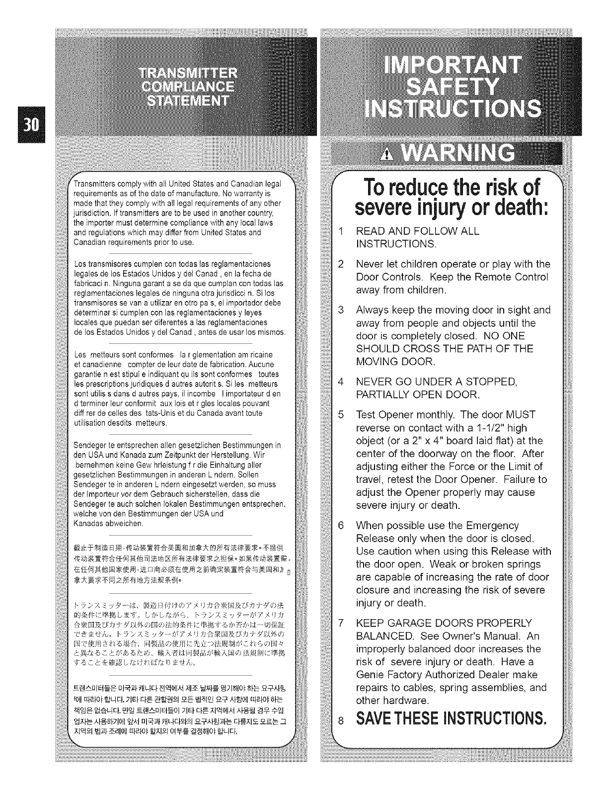
Toreducethe riskof
severeinjury or death:
READ AND FOLLOW ALL
INSTRUCTIONS.
Never let children operate or play with the
Door Controls. Keep the Remote Control
away from children.
Always keep the moving door in sight and
away from people and objects until the
door is completely closed. NO ONE
SHOULD CROSS THE PATH OF THE
MOVING DOOR.
NEVER GO UNDER A STOPPED,
PARTIALLY OPEN DOOR.
Test Opener monthly. The door MUST
reverse on contact with a 1-1/2" high
object (or a 2" x 4" board laid flat) at the
center of the doorway on the floor. After
adjusting either the Force or the Limit of
travel, retest the Door Opener. Failure to
adjust the Opener properly may cause
severe injury or death.
When possible use the Emergency
Release only when the door is closed.
Use caution when using this Release with
the door open. Weak or broken springs
are capable of increasing the rate of door
closure and increasing the risk of severe
injury or death.
7 KEEP GARAGE DOORS PROPERLY
BALANCED. See Owner's Manual. An
improperly balanced door increases the
risk of severe injury or death. Have a
Genie Factory Authorized Dealer make
repairs to cables, spring assemblies, and
other hardware.
SAVETHESEINSTRUCTIONS.
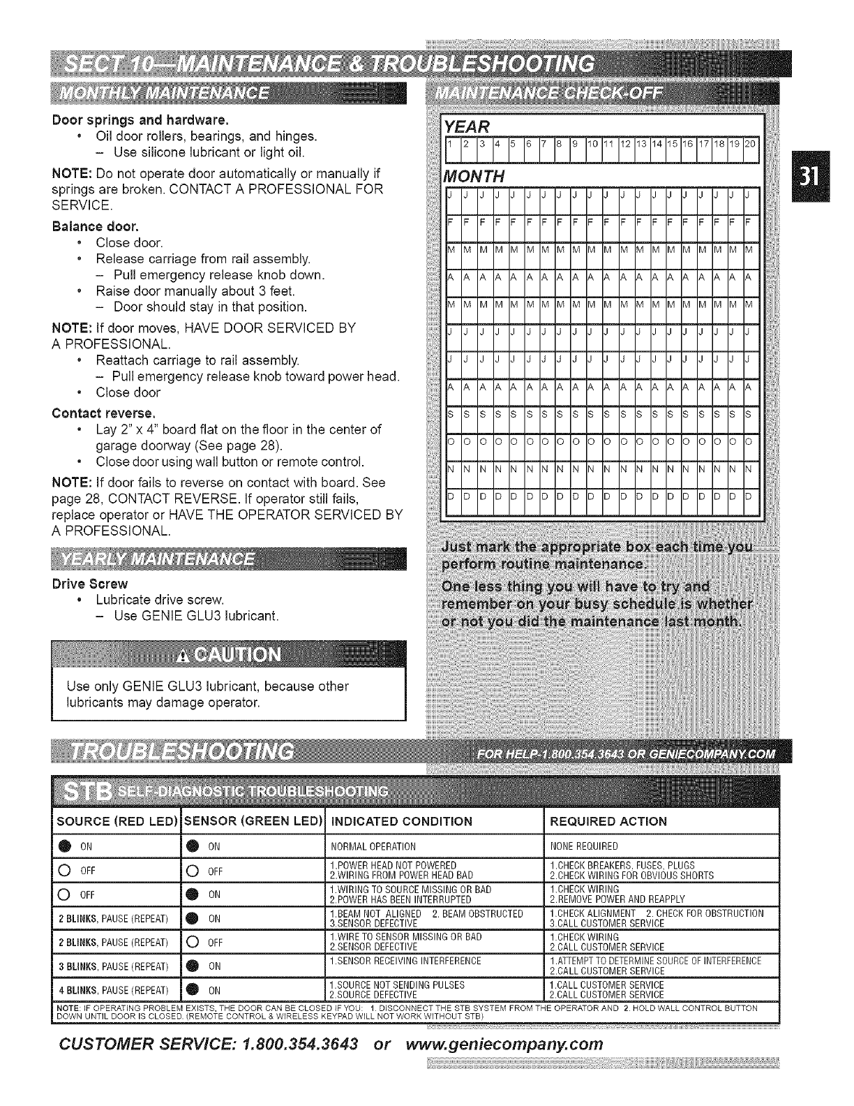
Door springs and hardware.
• Oil door rollers, bearings, and hinges.
- Use silicone lubricant or light oil.
NOTE: Do not operate door automatically or manually if
springs are broken. CONTACT A PROFESSIONAL FOR
SERVICE.
Balance door.
• Close door.
• Release carriage from rail assembly.
- Pull emergency release knob down.
• Raise door manually about 3 feet.
- Door should stay in that position.
NOTE: If door moves, HAVE DOOR SERVICED BY
A PROFESSIONAL.
• Reattach carriage to rail assembly.
- Pull emergency release knob toward power head.
• Close door
Contact reverse.
• Lay 2" x 4" board flat on the floor in the center of
garage doorway (See page 28).
• Close door using wall button or remote control.
NOTE: If door fails to reverse on contact with board. See
page 28, CONTACT REVERSE. If operator still fails,
replace operator or HAVE THE OPERATOR SERVICED BY
A PROFESSIONAL.
YEAR
Drive 8crew
• Lubricate drive screw.
- Use GENIE GLU3 lubricant.
Use only GENIE GLU3 lubricant, because other
lubricants may damage operator.
SOURCE (RED LED
0 ON
0 OFF
0 OFF
2 BLINKS, PAUSE(REPEAT)
2 BLINKS, PAUSE(REPEAT)
3BLINKS, PAUSE(REPEAT)
INDICATED CONDITION REQUIRED ACTIONSENSOR (GREEN LED
Q ON
0 OFF
0 ON
0 ON
0 OFF
• ON
0 ON
NORMAL OPERATION NONEREQUIRED
1.POWERHEAD NOT POWERED 1.CHECKBREAKERS,FUSES, PLUGS
2.WIRING FROM POWER HEAD BAD 2.CHECK WIRING FOR OBVIOUSSHORTS
1.WIRING TOSOURCE MISSING OR BAD 1.CHECKWIRING
2.POWER HAS BEENINTERRUPTED 2.REMOVE POWERAND REAPPLY
1.BEAM NOT ALIGNED 2. BEAM OBSTRUCTED 1.CHECK ALIGNMENT 2. CHECKFOR OBSTRUCTION
3.SENSOR DEFECTIVE 3.CALL CUSTOMERSERVICE
1.WIRE TO SENSORMISSING OR BAD 1.CHECKWIRING
2.SENSOR DEFECTIVE 2.CALL CUSTOMERSERVICE
1.SENSOR RECEIVINGINTERFERENCE 1.ATTEMPTTO DETERMINESOURCEOFINTERFERENCE
2.CALL CUSTOMERSERVICE
1.SOURCENOTSENDINGPULSES 1.CALLCUSTOMERSERVICE
4 BLINKS,PAUSE(REPEAT) 2.SOURCEDEFECTIVE 2.CALLCUSTOMERSERVICE
NOTE: IF OPERATING PROBLEM EXISTS, THE DOOR CAN BE CLOSED iF YOU: I DISCONNECT THE STB SYSTEM FROM THE OPERATOR AND 2 HOLD WALL CONTROL BUTTON
DOWN UNTIL DOOR IS CLOSED. (REMOTE CONTROL & WIRELESS KEYPAD WILL NOT WORK WITHOUT STB)
ii::
CUSTOMER SERVICE: 1.800.354.3643 or www.geniecompany.com
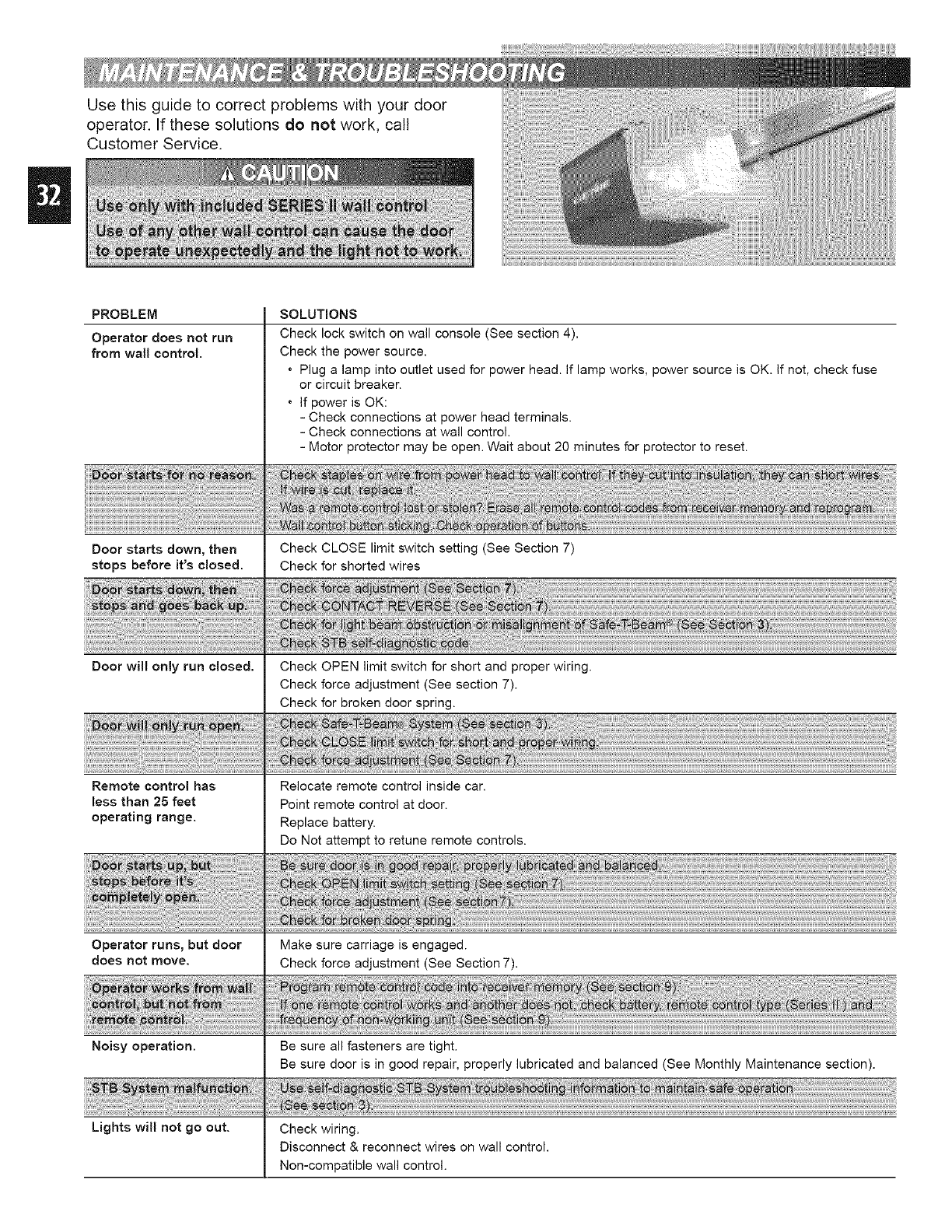
Use this guide to correct problems with your door
operator. If these solutions do not work, call
Customer Service.
PROBLEM
Operator does not run
from wail control,
Door starts down, then
stops before it's closed.
Door will only run closed.
Remote control has
less than 25 feet
operating range.
Operator runs, but door
does not move.
SOLUTIONS
Check lock switch on wall console (See section 4).
Check the power source.
• Plug a lamp into outlet used for power head. If lamp works, power source is OK. If not, check fuse
or circuit breaker.
• If power is OK:
- Check connections at power head terminals.
- Check connections at wall control.
- Motor protector may be open. Wait about 20 minutes for protector to reset.
Check CLOSE limit switch setting (See Section 7)
Check for shorted wires
Check OPEN limit switch for short and proper wiring.
Check force adjustment (See section 7).
Check for broken door spring.
Relocate remote control inside car.
Point remote control at door.
Replace battery.
Do Not attempt to retune remote controls.
Make sure carriage is engaged.
Check force adjustment (See Section 7).
Noisy operation. Be sure all fasteners are tight.
Be sure door is in good repair, properly lubricated and balanced (See Monthly Maintenance section).
Lights will not go out. Check wiring,
Disconnect & reconnect wires on wall control.
Non-compatible wall control.
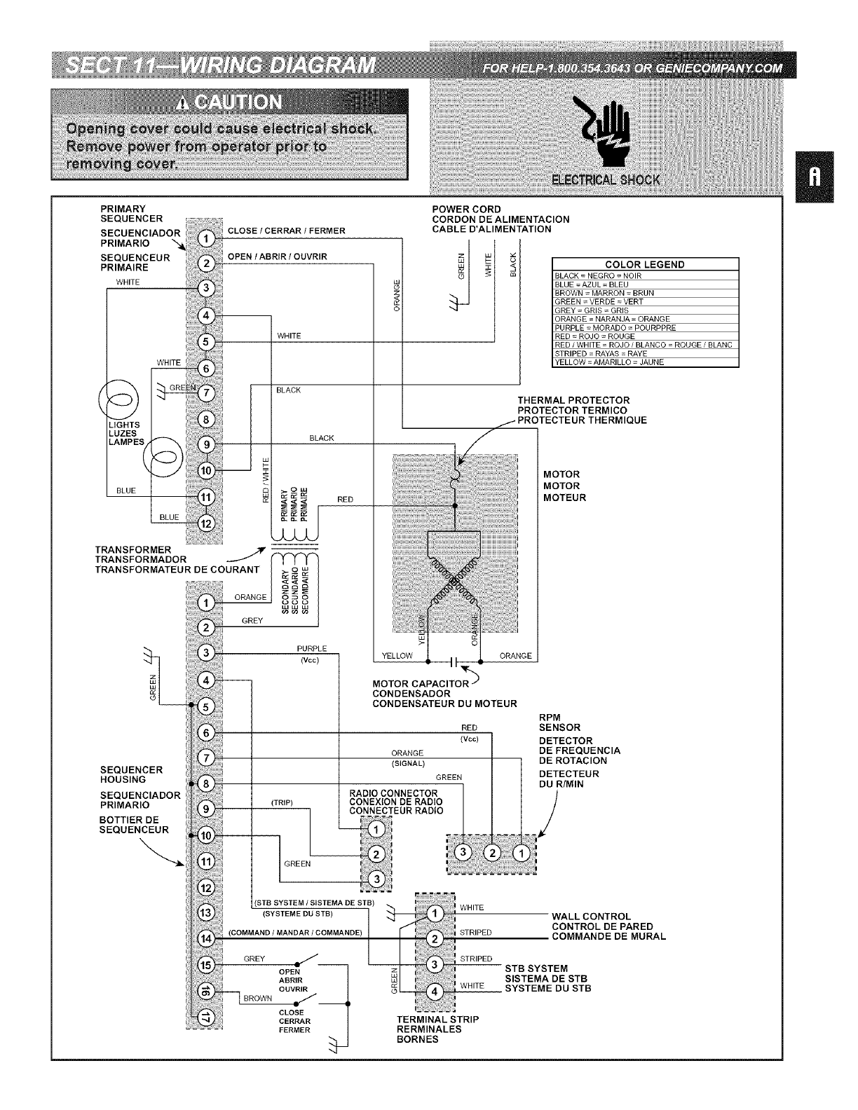
PRIMARY
SEQUENCER
SECUENCIADOR
PRIMARIO
SEQUENCEUR
PRIMAIRE
WHITE
WHITE
"-,,--J I
LIGHTS
-UZES
-AMPESj
BLUE
TRANSFORMER
CLOSE /CERRAR /FERMER
OPEN /ABRIR /OUVRIR
WHITE
h BLACK BLACK
< < < RED
POWER CORD
CORDON DE ALIMENTACION
CABLE D'ALIMENTATION
m
COLORLEGEND
BLACK= NEGRO =NOIR
BLUE =AZUL= BLEU
BROWN= MARRON=BRUN
GREEN =VERDE=VERT
GREY= GRIS = GRIS
ORANGE = NARANJA = ORANGE
PURPLE= MORADO = POURPPRE
RED = ROJO = ROUGE
RED/WHITE=ROJO/BLANCO=ROUGE/BLANC
STRIPED = RAYAS = RAYE
YELLOW =AMARILLO =JAUNE
THERMAL PROTECTOR
PROTECTOR TERMICO
THERMIQUE
MOTOR
MOTOR
MOTEUR
U
What is covered: Any defect in matedal and workmanship from
personal, normal household usein accordance with the
Owner's Manual
For how long:
H4000A-2 Series... Motor 10 years and all other parts 2 years.
H6000A-2K Series. Motor 15 years and all other parts 3 years.
18525 Series ...... Motor 2 years and all other parts 2 years.
18550-1 Series .... Motor 7 years and all other parts 2 years.
18550-2 Series .... Motor 10 years and all other parts 2 years.
ISS50-2X Series... Motor 12 years and all other parts 2 years.
18850-2M Series... Motor Lifetime* and all other parts 3 years.
18900-1 Series .... Motor 10 years and all other parts 2 years.
18900-2 Series .... Motor Lifetime* and all other parts 2 years.
18920 Series ..... Motor Lifetime* and all other parts 2 years.
ISL9S0 Series .... Motor Lifetime* and all other parts 3 years.
ISL900 Series ..... Motor and all other parts Lifetime*.
CM7600 Series.... Motor 10 years and all other parts 0 years.
CM8600 Series.... Motor Lifetime and all other parts 5 years.
PRO 95 Series..... Motor and all other parts Lifetime*.
*Lifetime l,varranty- warranted for as long asyou own your home
Who Gets the Warranty: The warranty ie limited to the
consumer who originally purchased the product.
Geographic Scope: This warranty applee only to Genie
products purchased in the United Statee and Canada.
What we wig do: If your Genie product is defective, we wil
send replacement parts or, at our option, replace it at no charge
to you. if we send replacement parts for your Genie product, we
may uee new or reconditioned replacement parts. If we choose
to replace your Genie product, we may replace it with a new or
reconditioned one of the same or eirnlar design.
LimitaDons: iMPLiEDWARRANTIES,INCLUDINGTHOSEOF
FITNESSFORA PARTICULARPURPOSEAND MERCHANTABILITY
(AN UNWRITTENWARRANTYTHATTHE PRODUCTIS FITFOR
ORDINARYUSE)ARELIMITEDTOONEYEARFROMDATEOF
PURCHASE.GENIEWiLL NOTPAYFOR;LOSSOFUSEOF
YOURGENIEPRODUCTOR PROPERTYDAMAGECAUSEDBY
YOURGENIEPRODUCTOR ITS FAILURETO WORK;ANY
SPECIAL,INCIDENTALOR CONSEQUENTIALDAMAGES;ANY
DAMAGESRESULTINGFROMMISUSEOR MODiFiCATiONOF
YOURGENIEPRODUCT.
Some statesand provincesdo not alow lirngationeon how long
an impled warranty laetsorthe exclusionof incidentalor
consequentialdamages,so theaboveexclusionemaynot apply.
Dewto get Warranty Service: To getwarranty servicefor your
Genie product, you must provide proof of date,and placeof
purchaseof the product.
1. Do-it-Yonrself-Service:CallGenieConsumerComlection toll
free at 1-800-354-3643. TrainedGenie representativeswil assist
in diagnosingthe problem and will arrangeto supply you with
required partsfor do-g-yoursel repairs. Trainedservice
representativesareavailable Monday-Friday,8:00 AM -11:00
PM, and on Saturday,11:00 AM -8:00 PM EasternTime
(subjoGto holidays.)
2. Service FromAethorizedDealers:You canobtainthe nameof
a Genieauthorizeddealerby callingtheGenieConsumer
Connectionat 1-800-654-3643.g an authorizeddealer provides
warranty service, Geniewil notreimburseyouor otherwisebe
responeiblefor those charges.
Your choiceof any one ofthe abovedescribedservice options is
your remedy under this warranty.
What This Warranty Does NotCover: This warranty does not
cover batteries (which are consideredreplaceableparts,)
instalation, commercial use,defects resulting from accidents,
damagewhile in transitto our service location or damage
reeugingfrom agerations,misuseor abuse,lackof proper
maintenance,unauthorizedrepairor modilcatione of the
product, affixing of anyattachment not provided with the
product, programming of the Remote Control Devices,
Safe-T-Beam®adiustment/Meaning,stapleethrougll wiring,
pinched or broken wires, Carriagedisengaged,ForceControl
adjustments, door out of balance, broken springs or cables,
power outages, ueeof extensioncords, rniesing or damaged
parts on discounted, Mearanced,final sale or taped cartons,
phantom operations (labor is not coveredif Openeris
functioning properly whfe teelmician is in garage), fire, Iced,
acts of God, or fafure to follow the Owner's Manual
This warranty is Die only one we wig give off yoor Genie
prodact, and it sets forth all oer responsibilities regarding
yoor Genie prodact. There are no other express warranties.
State and Province Rights: This warranty gives you specific
legal rights, and you may also have other rights that vary from
state to state add province to province.
Lo qne estd cuhierto: todo defeeto en matedales y mane de obra en el
use domGstieo personal y normal deacuerdo con el Manual del
PropietaNo.
DuraciSn:
Sede H4000A-2... Motor 10 ales y todas las demos piezas 2 ales.
Sede H6000A-2K.. Motor 15 aSos y todas las demos piezas 3 a£os.
Sede IS525 ...... Motor 2 a£os y todas las demos piezas 2 a£os.
Sede IS550-1 ..... Motor 7 aSos y todas las demos piezas 2 aSos.
Sede IS550-2 ..... Motor 10 ales y todas las dem£s piezas 2 ales.
Sede IS550-2X.... Motor 12 ales y todas los dem£s piezas 2 ales.
Sede IS850-2M... Motor Vgale[a y todas las demos piezas0 ales.
Sede IS900-1 ..... Motor 10ales y todas las demos piezas 2 ales.
Sede IS900-2 ..... Motor Vgale[a* y todas los demos piezas 2 ales.
Sede IS920 ...... Motor Vgale[a* y todas las dem£s piezas2 a£os.
Sede ISL950 ..... Motor Vgale[a* y todas las demos piezas0 a£os.
Sede ISL980 ..... Motor y todas los dem£s piezas Vgalicia.
Sede CM7600 .... Motor 10ales y redes los demos piezas 3 ales.
Sede CM8600 .... Motor Vgale[a* y redes las demos piezas 5 ales.
Sede PRO95 ..... Motor y todas las demds piezas Vitalicia*.
*Garantfa Vitaticia =se garantiza mientras usted sea el propietario de
su ease
zQuidn ohDene la garantia? La garantia est£ limitada al consumidor
que eompr0 originalmente el produeto.
Aleaace geogr_fice: Esta garanla se ap]ica sGIoa los produetos Genie
eomprados en los Estados Unidos y Canada.
Lo gee haremos: Si su produeto Genie es defectuoso, mandaremos el
reemplazo los partes o, a ope[Gn nuestra, Io reereplazaremos sin cargo
alguno para usted. Si mandamos el reemplazo las partes su producto
Genie, podemos user piezas de reereplazo nuevas o reacondicionadas.
Si optamos per cambiar su producto Genie, podemos camhiarlo per
uno nuevo o reacondicionado del mismo diseio o similar.
Limita¢ienee: LASGARANTJAS IMPL[CITAS, INCLUYENDO
AQUELLAS DE CONVENIENCIAPARA UN PROPOSITO PARTICULARY
COMERCIABILIDAD (UNA GARANTiANO ESCRITAQUE EL
PRODUCTOES APR_OPIADOPARAUSO ORDINARIO) ESTAN
LIMITADAS A UNANO A PARTIR DE LA FECHADE COMPRA.GENIE
NOPAGAR,_ POR PERDIDA DEL use DE SU PRODUCTO GENIE0
POR DAi/OS DE PROPIEDADCAUSADOS POR SU PRODUCTOGENIE
O POR LA FALLA DE TRABAJAR; POR DA%S CUALESQUIERA
ESPECIALES,INCIDENTALES0 EMERGENTES;PeR DANOS
RESULTANTESDEL MAL USO 0 LA MODIFICACIONDE SU
PRODUCTOGENIE.
AIgunos estados y provine[as no permiten limitaciones del tiempo que
dura la garantia implega o la exclusion de dales ine[dentales o
e[rcunstane[ales, entonees puede que los limitaciones de ardba no se
aplquen.
CSmo obtener servieio de garaoDa: Para obtener swvie[o de garantia
pare su producto Genie, usted debe proporeionar prueba de la fecha y
lunar de la eompra del produeto.
1. Servicio de hHcelaje: Llamar sin cargoala conexiGndel censumider
de Genie, mamande e] 1-000-354-3643. Representantesentrenades de
Genie le adstir_n endiagnoslcar e] prebiema y har£narregles pare sum-
inistrade ]aspiezas necesadas para los reparacienes debdcelaie e sea que
ustedmismo haga.Los representanfesde servicio entrenadosest_n
disponibJesde Noes a viemes, de 0:00 a.m. a 11:00 p.m. y los s£bades
de 11:00 a.m. a 8:00 p.m. hera del Este (sujete a feriades).
2. 8ervicio de distrihoidoree autorizados: Usted puede obtener el
hombre del distNhuidor autodzado de Genie lamando ala eonexiSn de[
eonsumidor de Genie, mareando el 1-800-654-3643. Si (in
distNhuider autodzado exlende una garantia de servicio, Genie no le
reemholsar£ austed ni ser_ responsable per esos cargos.
Su elecciOn de cualesquiera de los opciones de los servieios descNtos
ardba es el reeurso que tiene baio esta garantia.
Qn6 Eeta Garantia no Cnhre: Esta garantia no cubre baterias
(que coneidera lae partes reemplazables,) la instalaci0n, el use
de la propagaHda, los defeetos resultando de aeeidentes, el
dale mientrae en tr_nsito a nuestra ubieaciSn de[ eervieio o
resugar de dale de modgicacionee, el magrato o el abuse, la
faga de la coneervacion apropiada, la reparaeiGn o las
modgieaeiones no autodzadas del producto, porter de ninguna
fijaci0n no proporcion8 con el producto, programar de los
Diepositivoe del Mando a distancia, de T de Rayo Segura® el
ajuste/lirnpiar, Los alambres pelizcados o rotes, el Coche sonG,
los ajustee del Control de la Fuerza, la puerta fuera de
equlibdo, los pDmaveras o los cables rotes, lee fallas del poder,
el use de cuerdae de exteneion, perdiendo o lae partes daladas
en descontado, Mearanced, la venta final o los cartones
grabados, las operaciones fantasmales (el trabajo no se cubre
s[ el Abrelatae funciona apropiadamente ngentras tGcnieo eet_
en el garaje), el fuego, la inundaciGn, los actoe de la naturaleza,
o el fra.
Esta gaiantia es ]a uoiea que daremes a so prodnctoGenie, y
esgpula tedas nnestras respensahilidades con respeetoasn
prodocto Genie. No hay otras garanDas expresas.
Dereches de estados y previocias: Esta garantia le otorga dereehos
legales especgicos y puede que usted tenga tambidn otros dereehos
que varian de estado a eetade y de previncia a provincia.
Ce gu'eRe eenwe: toute dGfectuosit6 de matGNauet tout d_faut de fab-
rication constaf_s pendant Rdilsation norman du produit par un indi-
vidu 8 son domicile en conformed avec le Manuel de I'utilisateur.
Peedaot cemhien de temps:
SGNeH4000A-2... Moteur 10 anset toutes les autres pi_ces 2 ans.
SdNe H6000A-2K.. Moteur 15 anset toutes los autres pi_ces 3 ans.
SdNe 18525....... Moteur 2 anset toutes los autres pi_ces2 ans.
SGNe18550-1 ..... Moteur 7 anset routes los autres pi_ces2 ans.
SdNe 18550-2 ..... Moteur 10 anset routes los autres pi_ces 2 ans.
SdNe 18550-2X.... Moteur 12 anset toutes los autres pi_ces 2 ans.
SGNe18850-2M ... Moteur _ vie* et routes los autres pihces 3 ans.
SdNe 18900-1 ..... Moteur 10anset toutes lee autres pi_ces 2 ans.
SGNe18900-2 ..... Moteur _ vie*et teutes los autres pi_ees 2 ans.
SGNe18920....... Moteur _ vie*et teutes los autres pi_ees 2 ans.
SdNe ISLES0...... Moteur 8 vieet toutes los autres pi_ees 3 ans.
SGNeISLg80 ...... Moteur et toutes los autres pihees & vie'.
SdNeCM7600 ..... Moteur 10 anset routes los autres pi_ces 3 ans.
SdNeCM8600 ..... Moteur 8 vieet toutes los autres pi_ees 5 ans.
SGNePRO95 ..... Moteur et toutes los autres pihees 8 vie'.
*Garantie D vie =Garanti rant que vous restez propri_taire de votm
habitation
BGnGficiaire de la garantie: La garantie est limitGe au client qui a
acheth ingialement le produit.
Pays converts: Cette garantie s'app]ique eeulement aex produgs
Genie aehetGs aux htats-Unis et Canada.
Nee cendiDens: Sile produg Genie est dhtectueux, noue enverrons
los parties de replacement ou, solon notre choix, de le remplacer
sane Trois de notre part. Si nous envoyons lee parties de
replacement du produg, il est possiMe que nous uRlieions des
pidces de remplacement neuves ou reeondgionnhes. Si noue
dGe[done de rempiacer le produg Genie, il est possible que nous le
remp]ae[ons avec un produg neut ou recondgionnd de conception
semblable.
Limites: LES GARANTIES IMPLJCITES, Y COMPRIS LES
GARANTIES D'A-DAP-TA-TION A UN USA-GE PAR-TI-CU-LIER ET
LA GA-RAN-TIE DE VALIDITE MAR-CHAN-DE (UNE GARANTIE
TACITE QUE LE PRODUIT EST ADAPTE A L'USAGE) SeNT
LIMITEES A UN AN A COMPTER DE LA DATE D'ACHAT. GENIE
DECLINE TOUTE RESPONSABILITE EN CAS DE PERTE
D'UTILISATION DU PRODUIT OU DE DOMMAGES MATERIELS
CAUSES PAR LE PRODUIT GENIE OU PAR UN FONCTIONNEMENT
DEFECTUEUX ; DE DOMMAGES ACCIDENTELS OU INDIRECTS ;
DE DOMMAGES ISSUS DE L'UTILISATION INCORRECTE OU DE
LA MODiFICATiON DU PRODUIT GENIE.
Certains 6tats et provinces n'autodsent pas los limites de durhe
des garantiee impiicites ou I'exclusion des dommages aecidentels
ou indirects. Dane ce cos, los exclusions ci-dessue ne
s'appliquent pae.
Comment hGnhfieier dn service offert par la gerantie: Pour
pouvoir en bGnhficier, il veus Taut fournir une justifieatiw_ de la
date et du lieu de I'achat.
1, Service pont eflectner los r_peretiene soi-mhme: Appeler le
numGro saus trais du service a la clenthle Genie 1-800-354-3643.
Des agents Genie spdcialsGs vous aideront a diagnoetiquer le
probl_me et prendront lee dispositions n_ceesaires pour vous
lournir los piGces requises are que vous puiss[ez effectuer los
rGparations par vous-m£me. Voue pouvez joindre ce service de
lundi au vendredi, de 8 h _ 23 het le eamedi, de 11 h a 20 h,
heure de I'Est (saul louts fdriGs)
2, Service effeetn_ par dee teehnieiens egreds: Appeler le service
8 la c]ientGle Genie au 1-800-654-3643 qui vous communiquera le
nora d'un technicien agrGh. Sile technicien agrGh ottre un service
de garantie, lee trais encourus ne seront pas rwobours6s par Genie
et Genie ne serapas tenu responsable du rGglement des frais.
Le choix de I'une des options de service dGcdte cbdessus eet le
recours dent vous disposez sous cette garantie.
Que Cette Garantie Poe Couverture: Cette garantie pas piles
couverture (qui sontdls considhr6 des parties rempia_ablee,)
instalation, usage, dGfauts Rayon rGsuiter de accidents,
dommages dans travers_e _ notre enlplacenlent service ou
pas domrnagee qui rhsuge de ehangements, ou abus, is/anque
d'entretien propre, rhparation ou modgieations inautorisGe du
produg, apposant d'attachement cot foum[ avee le produg,
programmant de H, de T de Rayon SQr® ajustement
nettoyage,Fis pincGs ou casshs, I'Attelage a dGcienchh, los
aiustements de ContrOle de Force, la porte d'hqulibre, lee
reeeort ou lee c£bles caesGe, lee coupuree de courant, I'ueage
de ralonges, manquant oua endommagh des parties sur
escomptG, Mearanced, la vente finale ou a enregistrh des boles,
les opGrations fantSmes (la main-d'oeuvre n'eet pae couverte e[
I'Ouvre-botte fonctionne convenablement pendant que le
technicien est dane le garage), le feu, I'inondation, lee dhsastres
naturels, ou i'Gchec pour suivre le Manuel du Proprihtaire.
Cette garantie est la seole garanDe fonrnie poor le prednit et fait
valoir tontes los responsahgg£s qni vens incemhent cencernant
le produit Genie. R n'y e pas d'eotres garanties expresses.
Dregs pour los £tats et les provinces: Cette garantie vous donne
des droits jeddiques spGcgiques; los autree dregs peuvent vader
d'un atat a I'autre et d'une province a I'autre.
Z
o
==
2
o
=o
t_
,,=,
Z
o
S
,,=,
o
2
w
o
w
8
o
=o
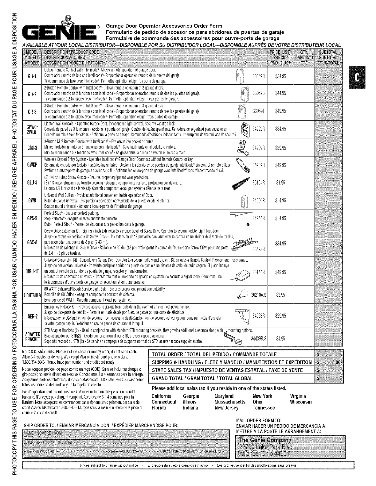
Garage Door Operator Accessories Order Form
Formulario de pedido de accesorios pare abridores de puertas de garaje
Formutaire de commande des accessoires pour ouvre=porte de garage
AVAILABLEATYOURLOCALDISTRIBUTOR=DISPONIBLEPORSU DISTRIBUIBORLOCAL=BISPONIBLEAUPRESBEVOTREDISTRIBUTEURLOCAL
DeLuxeRemoteContrdwithIntdlicode÷-ALlowsremoteoperationofgaragedoor.
GIT-1 ControladorremotodeLujoconLntdLicode÷-ProporoibnaroperacibnremotodeLapuertaddgaraje. 33069R $34.95
T_l_commandedeluxeavecIntdlicode÷-Permettraopdration_Loign"deportedegarage.
2-ButtonRemoteControlwithIntdlJcode_-AHowsremoteoperationof2garagedoors.
GIT-2 Controladorremotode2fundonesconIntellicode÷-Proporcidnaroperacidnremotodedoslaspuertaadelgaraie. 33069S $44.95
Td_commande_2fonctionsavecIntellicode÷-Permdtraopdration_Loign"deuxportesdegarage.
3-ButtonRemoteControlwithIntdlicode'_-Allowsremoteoperationofggaragedoors.
GIT-3 Controladorremotode3funcionesconIntdlicode÷-Proporcienaroperacienremotodetreslaspuertasdelgaraie. 33069T $49.95
Td_commandea3fonctionsavecIntellicode÷-Permdtraoperationdoign'troisportesdegarage.
LightedWaLlConsole-OperatesGarageDoor.independentlightcontroL.Securityvacationlock.
GPWC" Consoledeparedde3 funciones-Acetonelapuertaddgaraie.Controldeluzindependiente.Cerraduradeseguddadparevacaciones. _ 34292R $34.95
2WLB Consolemurale_ troisfonctions- Actionnelaportedegarage.Commandod'_dairageinddpendante.InterrapteurdeverroudLagedesdcudtd.
3-ButtonMiniRemoteControl/dtbIntdlicode_- Fitseadlyintopocketorpurse.
6MI-3 Minicontrdadorremotode3funcionesconIntellicode÷-Cavefdcdmenteenelbdsdloo cartera. _ 34909R $39.95
Minitdldcommande_3fonctJonsavecInteJiicode- segJissedanslapochedevestonoulesac&main.
.%
WirelessKeypadEntrySystem-OperatesIntdLicodeGarageDoorOperatorswithoutRemoteContrdorkey.
DWKP Sistemadeentradapottedado .......... _ '35282R $49.95numenoomaLambnoo-AcolonaLosabndorasdepuertasdegaraIeLntelhcodesincontrdremotoo LLave.
Systemedouvra-portedegarageaclaviersanshi- Actlonneleeouvra-portedegarageavecletdhcodesanstdeoommandenlole.
(3)1/4oz.tubesScrewGrease-Ensuresproperequipmentwearprotection.
DW-3 (3)1/4oncelubdcantedetomiHoaccionar-Aseguracomponentecorrectoprotectionpordetedoro. 35164R $1.95
Laonza1/4lubdcantdelavis(3)-Garantircomponentexactparsyst_med_fenseversuser.
UniveraalWallButton-ProvidesadditionalconvenientinsideoperationofDoor.
GWB Botbndepareduniversal-Proporcionaoperacibnconvenientedelapuertadesdeelinterior. 34960R $ 4.95
Boutonmuraluniverael-ActionneI'ouvra-portedeI'intdrieurdugarage.
PerfectStop÷-Ensuresperfectparking. _jf_-
6PS-5 StopPerfecto_-Aseguraelestacionamientoperfecto. _ _ 34964R $ 4.95
ButoirPerfectStop_-Permetdestationner_laperfectiondenslegarage.
ScrewDriveExtensionKit-EighteeninchExtensiontoincreasetravdofScrewDriveOperatortoaccommodateeightfootdoor.
JuegodeextensigndedizantedeScrewDrive-Unaextensiende18pulgadaspareaumentarlacameradeunabddordeslizabledetornHIo_.................................................................
DSX-8 pareacomodarunapuertade8 pies(2,43m.). _ $34.95
NdcessairaderaLIongeduScrewDrive-RaLIongede30dm(18pc)prdongeantlacoursedePouvra-porteScrewDrivepouruneporte_=_-_ 33523R
de2,4m(8pi)dehauteur.
UniversalConversionKit-ConvertsanyGarageDoorOperatortoesecureradiosignalsystem.Kitincludesa RemoteControl,ReceiverandTransformec.
Juegodeconversibnuniveraal-Conviertecualquierabddordepuertadegaraiea unsietemadesebalderadioseguro.Eliuegoincluye
GIRU-1T uncontrolremotodeabddordepuertadegaraje,receptorytransformador. _ 33154R $49.95
Ndcessairadeconversionuniversal-Transformetoutouvra-portedegarageensyst_medes_cudt__signalradio.Comprendune
td_commanded'ouvre-portedegarage,unr_cepteuretuntransformateuc
60WATTEnhanced/RoughServiceLightBuLb-Ensuresproperequipmentcompatability.
LIDHTBULBBombdlade60Vatios-Aseguracomponentecorrectodesistema. _ 26210A.S $2.95
Edairagede60WATT-Garantiroomponantexadparsyst_me.
EmergencyReleaseKit-Providesaccesstogaragefromoutsideintheeventofanelectricalpowerfailure.
Juegodepica-portedepestillo- Permitirentrtadadesdeporfueradegaraieporquecortedeel_ctdc.o
DER-2 N_cessairasdeD_clencbementdesecoura-Len_cessaireded_clenchementdesecoursestcon_upourvouspermettrad'acc_der 34963R $29.95
votragaragedepuisI'extddeurencasdepannedecourantetIoraqu'ik
STBAdapterBrackets(2)-UsedinconiundionwithstandardSTBmountingbrackets,theyprovideadditionalcleerancealongwith,_mountingoptions.
ADAPTERBRACKETBrasadaptadorporSTB(2)-UsadoconbrasnormalpotSTB,proveerespacioadicionak _ _ .........'_a,_'_Q_£ $4.95 ..........................................................
SupportsraccordduSTB(2)-SeservirencompagniedesupportsnormalduSTB,assurerespacesuppl_mentaira. -¢_
NoC.O.D.shipments.Pleaseincludecheckormoneyorder,donotsendcash.
Allow3-4weeksfordelivery.WeacceptVisaorMastereardphoneorders.
1.800.354.3643.Pleasehavepartnumberandcreditcardready
Noseaceptanpedidosdepagecentreentrega(COD).Sirvaseincluirsuchequeo
Direpostal;noenviedineroenetedivo.Concedanos3a 4semanasparalaentrega.
Aceptamospedidostelef0nicosdeVisao Nastercard.1.800.3£4.3643.Sirvasetoner
listoslosndmerosdelmodeloydelatarjetadecredito.
Pasd'expeditioncentreremboumement.Veuillezinclureunchequeouunmandat
bancaire.N'envoyezpasd'argentcomptant.Accordezde3a 4semainespourla
livraison.Nousacceptonsloscommandospartelephoneavecpaiementparcartede
creditVisaouNastercard.1.800.354.3643.Ayezsouslamainlenumerodelapieceet
celuidelacartedecredit.
TOTAL ORDER/TOTAL DEL PEDIDO /COMMANDE TOTALE
SHiPPiNG & HANDLING IFLETE YMANEJO IMANUTENTION ET EXPEDITION
STATE SALES TAX IIMPUESTO DE VENTAS ESTATAL ITAXE DE VENTE
GRAND TOTAL /GRAN TOTAL /TOTAL GLOBAL
Please add local sales tax if you reside in one of the states listed.
California Georgia Maryland New York
Connecticut illinois Massachusetts Ohio
Florida indiana New Jersey Tennessee
Virginia
Wisconsin
SHIPORDERTO:/ENVIARMERCANCiACON:/EXPI_DIERMARCHANDISEPOUR: MAILORDERFORMTO:
ENVIARHACERUN PEDIDODE MERCANCIAA:
METTREA LA POSTELE ARRANGEMENT/_:
Prices subiect to change without notice * El precio esta suieto a carnbios sin awso * Les prix peuvef_t subir des modifications sans preavis i
