GeoPrecision LAN905R10 LAN-Interface (US) User Manual Lan Interface
GeoPrecision GmbH LAN-Interface (US) Lan Interface
Contents
- 1. LAN_Interface_manual
- 2. Attachment to Manual
LAN_Interface_manual
Manual Deutsch / English V1.0 Release 15.07.2013
LAN-Interface-(US)
Herzlichen Glückwunsch Sie zum Kauf Ihres neuen LAN-Interfaces. Sie haben damit ein dem neuesten Stand der Technik entsprechendes
Gerät erworben. Bitte lesen Sie diese Kurz-Anleitung genau durch, bevor Sie das Gerät installieren.
Best.-Nr. Gerätetyp
LAN-INTERFACE LAN Interface 433,92 MHz Version
LAN-INTERFACE-US LAN Interface 915 MHz USA Version
Allgemeine Beschreibung
Das LAN-Interface ermöglicht unter Verwendung einer Ethernet-Infrastruktur die Kommunikation mit drahtlosen Geräten über eine größere
Entfernung hinweg. Die Platzierung mehrer Interfaces an unterschiedlichen Standorten ermöglicht den Zugriff auf räumlich verteilte Endgeräte
von einem zentralen Ort aus. Diese Kurzanleitung behandelt die Standortwahl, Aufstellung und den Anschluss des Interfaces.
Hinweise zur Nutzung
Zur Nutzung des LAN-Interfaces wird eine konfigurierte Ethernet-Infrastruktur mit 100MBit Übertragungsrate benötigt. Das Gerät ermöglicht im
Zusammenspiel mit der HW4-Software die Kommunikation mit geeigneten Funkgeräten. Zur Konfiguration der Ethernet-Parameter des LAN-
Interface wird ein PC mit HW4 oder einem gängigen Webbrowser (z.B. Firefox, InternetExplorer) benötigt, welcher in die gleiche Ethernet-
Infrastruktur eingebunden ist. Das LAN-Interface und das mitgelieferte Steckernetzteil sind ausschließlich für die Verwendung im
Innenraumbereich ausgelegt.
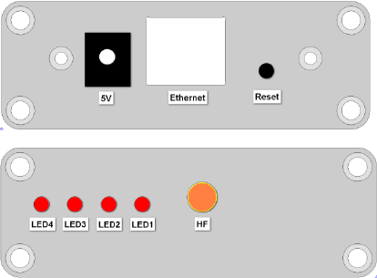
Geräteansicht und Standardkonfiguration
Rückansicht:
Frontansicht:
Anschlüsse und LED’s:
5V Netzteilanschluss
Ethernet RJ45-Netzwerkanschluss
Reset Drucktaster zum Zurücksetzen der Netzwerkkonfiguration in den Auslieferungszustand.
HF Antennenanschluss
LED1 Spannungsversorgung
LED2 Funkdaten werden gesendet (blitzend)
LED3 Empfangene Funkdaten werden verarbeitet (blitzend)
LED4 Status, blinkend in folgenden variablen Intervallen (s.u.)
Das LAN-Interface ist bei Auslieferung mit folgenden Netzwerkeinstellungen konfiguriert:
IP 192.168.1.120
Netmask 255.255.255.0
Gateway 192.168.1.1
DNS 192.168.1.1
Netzwerkname rotroniclan
DHCP an
GP-Port 6767
Standortwahl
Für eine optimale Sende- und Empfangsreichweite ist der Standort in trockenen Innenräumen nach folgenden Kriterien zu wählen:
• Waagerecht, frei zugänglich (nicht durch Gegenstände verstellt)
• Keine metallischen Gegenstände (Wasserleitungen, Stahlschränke, o.ä.)
• Idealerweise besteht eine „Sichtverbindung“ zwischen Antenne und anzusprechendem Gerät
• Sonneneinstrahlung, Feuchtigkeit und Temperaturwechsel vermeiden
Anschluss
Stabantenne im Uhrzeigersinn auf den goldfarbenen HF-Anschluss aufschrauben. Die Montage der Antenne erfolgt ausschließlich über die
Überwurfmutter. Das Gerät mit einem geeigneten Patchkabel über die Ethernet-Buchse mit der Netzwerkinfrastruktur verbinden. Den
Klinkenstecker des Netzteils mit der 5V-Buchse des Gerätes verbinden.
Hinweis:
Bei Änderungen am Antennen- oder Netzwerkanschluss ist das Gerät vorher vom Stromnetz zu trennen!
Reset:
Drucktaster zum Zurücksetzen der Netzwerkkonfiguration in den Auslieferungszustand
.
Erste
Inbetriebnahme:
Nachdem das Gerät zum ersten Mal mit dem Stromnetz verbunden wurde, leuchtet LED1 auf und das LAN-Interface durchläuft die folgende
Startphase, deren Status durch LED4 gezeigt wird:
25ms: Netzwerkkonfiguration wird per DHCP abgefragt.
100ms: DHCP-Anfrage Fehlgeschlagen, keine benutzerdefinierten Einstellungen vorhanden. Die Netzwerkschnittstelle wurde automatisch mit
den Werten bei Auslieferungszustand konfiguriert.
1s: Netzwerkkonfiguration wurde erfolgreich vom DHCP-Server bezogen.
2s: Benutzerdefinierte Netzwerkkonfiguration (DHCP-Nutzung deaktiviert).
Die Netzwerkkonfiguration sollte nun über das Webinterface oder die HW4-Software (siehe auch Dokumentation der HW4) angepasst und
individualisiert werden. (weiter Informationen s. Anleitung
)
Technische Daten:
Gehäuse Aluminium, Schutzart IP20
Antennenanschluss HF via 50Ω SMA-Stecker
Übertragungsdistanz der Funkschnittstelle: bis zu 100 m
Einsatzbereich -20 bis +85 °C, max. 90% Luftfeuchte
Netzwerkanschluss Fast Ethernet (10/100MBit) via RJ45-Stecker
Stromversorgung 5VDC Klinkenstecker
Stromaufnahme Max. 200 mA
LAN-Interface-(US)
Congratulations on your purchase of the new state-of-the-art LAN-Interfae. Please read these short instructions carefully before installing the
device.
General description
The LAN interface communicates with wireless devices over a greater distance by using an Ethernet infrastructure. The placement of multiple
interfaces in different locations provides access to spatially distributed devices from a central location. This quick reference guide is limited to
the description of the main features and the installation of the device.
Handling
The LAN interface requires a configured Ethernet infrastructure with a transfer rate of 100MBit. The device enables the interaction with the HW4
software to communicate with appropriate radio equipment. To configure the Ethernet parameters of the LAN interface, a PC with HW4 or a
standard Web browser (eg Firefox, Internet Explorer) which is integrated into the same Ethernet infrastructure is required. The LAN interface
and the included AC adapter designed exclusively for use in interior areas.
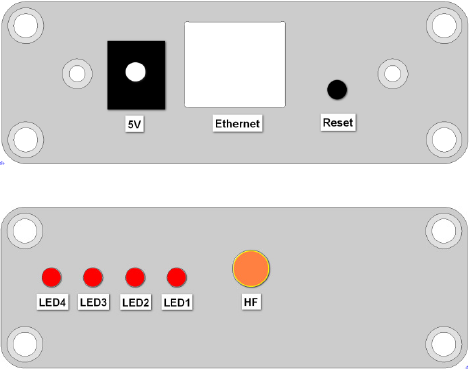
Device View and Standard Configuration
Rear view
Front view:
Connectors and LED’s
5V Power supply connector
Ethernet RJ45- Network Connection
Reset Push button to reset the network configuration to factory default.
HF Antenna connection
LED1 Power supply
LED2 Radio data is sent (blinking)
LED3 Received radio data is processed (flashing)
LED4 Status, blinking in the following variable intervals (see below)
The LAN interface is configured upon delivery with the following network settings
IP 192.168.1.120
Netmask 255.255.255.0
Gateway 192.168.1.1
DNS 192.168.1.1
Network name rotroniclan
DHCP on
GP-Port 6767
Choice of location:
For optimal transmission and reception range the interior site of placement has to meet the following criteria:
• Horizontal, freely accessible (not blocked by objects).
• Do not place close to metallic objects (water pipes, steel cabinets, etc.).
• Ideally, there is a "visual connection" between the antenna and the device.
• Avoid direct sunlight, moisture and temperature changes.
Connection
Screw the antenna clockwise to the gold colored RF connector. Mount he antenna only by turning the nut. Connect the device via the Ethernet
port to the network infrastructure by using an appropriate patch cable. Connect the AC adapter to the mains and the 5V jack of the device.
Note Prior to changes of the antenna or network connection, the device has to be separated from the mains!
Reset Push button to reset the network configuration to its factory defaults.
Initial Setup
After the device is connected for the first time the mains LED1 starts flashing. The LAN-Interface now follows the below start-up-sequence,
shown by LED4:
25ms: Network configuration is queried via DHCP.
100ms: DHCP request failed, no custom settings available. The network interface is
automatically configured with factory settings.
1s: Network configuration was successfully obtained from the DHCP server.
2s: Custom network configuration (DHCP disabled).
Now the network configuration should be customized by using HW4 software (further information see manual).
Technical Specifications:
Housing Alu, protection class IP20
Antenna connector HF via 50Ω SMA-connector
Transmission distance
of the radio interface Up to 100 m
Range of use -20 to +85 °C, max. 90% air humidity
Network Connection Fast Ethernet (10/100MBit) via RJ45 connector
Power Supply 5VDC jack connector
Current consumption Max. 200 mA
Please note: The devices are available with several different radio frequencies, depending on the local regulations of the country (e.g.: 433 MHz
in Europe, parts of Africa and Asia, 905 MHz in USA and Canada, ...). It is in the responsibility of the user, not to use devices that are not
allowed in the country of usage.
Compliance informations (only for USA/Canada):
a) User Information according to FCC 15.21:
Changes or modifications not expressly approved by the party responsible for compliance could void the user’s authority to operate the
equipment.
b) Part 15 Statement according FCC 15.19/RSS Gen Issue 3 Sect. 7.1.3
This device complies with Part 15 of the FCC Rules and with Industry Canada license-exempt RSS standard(s). Operation is subject to the
following two conditions: (1) this device may not cause harmful interference, and (2) this device must accept any interference received, including
interference that may cause undesired operation.
Le présent appareil est conforme aux CNR d'Industrie Canada applicables aux appareils radio exempts de licence. L'exploitation est autorisée
aux deux conditions suivantes : (1) l'appareil ne doit pas produire de brouillage, et (2) l'utilisateur de l'appareil doit accepter tout brouillage
radioélectrique subi, même si le brouillage est susceptible d'en compromettre le fonctionnement.
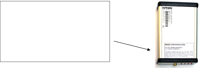
LAN-Interface (US): FCC-ID: 2AARELAN905R10 / IC Certification No IC: 11303A-LAN905R10
Model: LAN-Interface (US)
FCC-ID: 2AARELAN905R10
IC: 11303A-LAN905R10
This device complies with Part 15 of the FCC Rules.
Operation is subject to the following two conditions: (1) this
device may not cause harmful interference, and (2) this
device must accept any interference received, including
interference that may cause undesired operation.
(Label assembled on bottom side of the device)