Geophysical Survey Systems 3101A 3101A Antenna User Manual GENERAL FAXFORM
Geophysical Survey Systems, Inc. 3101A Antenna GENERAL FAXFORM
Users Manual
3101A Antenna
System Settings and User Notes
The World Leader in
Subsurface Ima
g
in
g
™
Geophysical Survey Systems, Inc.
Tel 603.893.1109 • Fax 603.889.3984
sales@geophysical.com
www.geophysical.com
August, 2010
Copyright© 2001, 2010 Geophysical Survey Systems, Inc.
All rights reserved
including the right of reproduction
in whole or in part in any form
Published by Geophysical Survey Systems, Inc.
12 Industrial Way Drive
Salem, New Hampshire 03079
Printed in the United States
GSSI, RADAN, and SIR are registered trademarks of Geophysical Survey Systems, Inc.
Geophysical Survey Systems, Inc. Model 3101A Series Antennas
System Settings and User Notes
Limited Warranty, Limitations Of Liability And Restrictions
Geophysical Survey Systems, Inc. hereinafter referred to as GSSI, warrants that for a period of
24 months from the delivery date to the original purchaser this product will be free from defects
in materials and workmanship. EXCEPT FOR THE FOREGOING LIMITED WARRANTY,
GSSI DISCLAIMS ALL WARRANTIES, EXPRESS OR IMPLIED, INCLUDING ANY
WARRANTY OF MERCHANTABILITY OR FITNESS FOR A PARTICULAR PURPOSE.
GSSI's obligation is limited to repairing or replacing parts or equipment which are returned to
GSSI, transportation and insurance pre-paid, without alteration or further damage, and which in
GSSI's judgment, were defective or became defective during normal use.
GSSI ASSUMES NO LIABILITY FOR ANY DIRECT, INDIRECT, SPECIAL, INCIDENTAL
OR CONSEQUENTIAL DAMAGES OR INJURIES CAUSED BY PROPER OR IMPROPER
OPERATION OF ITS EQUIPMENT, WHETHER OR NOT DEFECTIVE.
Before returning any equipment to GSSI, a Return Material Authorization (RMA) number must
be obtained. Please call the GSSI Customer Service Manager who will assign an RMA number.
Be sure to have the serial number of the unit available
Geophysical Survey Systems, Inc. Model 3101A Series Antennas
System Settings and User Notes
FCC Notice (for U.S. Customers):
This device complies with part 15 of the FCC Rules:
Operation is subject to the following conditions:
1. This device many not cause harmful interference, and
2. This device must accept any interference received, Including interference that may cause
undesired operation
Warning: Changes or modifications to this unit not expressly approved by the party responsible for
compliance could void the user’s authority to operate the equipment.
Operation of this device is restricted to law enforcement, fire and rescue officials, scientific research
institutes, commercial mining companies, and construction companies. Operation by any other party is a
violation of 47 U.S.C. § 301 and could subject the operator to serious legal penalties.
Coordination Requirements
(a) UWB imaging systems require coordination through the FCC before the equipment may be used. The
operator shall comply with any constraints on equipment usage resulting from this coordination.
(b) The users of UWB imaging devices shall supply detailed operational areas to the FCC Office of
Engineering and Technology who shall coordinate this information with the Federal Government through
the National Telecommunications and Information Administration. The information provided by the
UWB operator shall include the name, address and other pertinent contact information of the user, the
desired geographical area of operation, and the FCC ID number and other nomenclature of the UWB
device. This material shall be submitted to the following address:
Frequency Coordination Branch, OET
Federal Communications Commission
445 12th Street, SW
Washington, D.C. 20554
ATTN: UWB Coordination
(d) Users of authorized, coordinated UWB systems may transfer them to other qualified users and to
different locations upon coordination of change of ownership or location to the FCC and coordination
with existing authorized operations.
(e) The NTIA/FCC coordination report shall include any needed constraints that apply to day-to-day
operations. Such constraints could specify prohibited areas of operations or areas located near authorized
radio stations for which additional coordination is required before operation of the UWB equipment. If
additional local coordination is required, a local coordination contact will be provided.
(f) The coordination of routine UWB operations shall not take longer than 15 business days from the
receipt of the coordination request by NTIA. Special temporary operations may be handled with an
expedited turn-around time when circumstances warrant. The operation of UWB systems in emergency
situations involving the safety of life or property may occur without coordination provided a notification
procedure, similar to that contained in CFR47 Section 2.405(a)-(e), is followed by the UWB equipment
user.
Notice: Use of this device as a wall imaging system is prohibited by FCC regulations.
Geophysical Survey Systems, Inc. Model 3101A Series Antennas
System Settings and User Notes
Canadian Requirements for RSS-220
Canadian Requirements of RSS-220 for Ground
Antennas
This Ground Penetrating Radar Device shall be operated only when in contact with or within 1 m of the
ground.
This Ground Penetrating Radar Device shall be operated only by law enforcement agencies, scientific
research institutes, commercial mining companies, construction companies, and emergency rescue or
firefighting organizations.
Cet appareil de radar de sol (ou géoradar) ne doit être utilisé qu’en contact avec le sol ou à 1 m maximum
au dessus du sol.
Cet appareil de radar de sol ne doit être utilisé que par les forces de l’ordre, les instituts de recherche
scientifiques, les sociétés minières, les sociétés de construction, et les organisations de secours d’urgence
ou de combat du feu.
Canadian Requirements of RSS-220 for Hand-held
Antennas
This In-wall Radar Imaging Device shall be operated where the device is directed at the wall and in
contact with or within 20 cm of the wall surface.
This In-wall Radar Imaging Device shall be operated only by law enforcement agencies, scientific
research institutes, commercial mining companies, construction companies, and emergency rescue or
firefighting organizations.
Cet appareil de radar de structure (murs, poutres, dalles…) ne doit être utilisé qu’en contact avec la
structure ou à 20 cm maximum décollé de cette structure.
scientifiques, les sociétés minières, les sociétés de construction, et les organisations de secours d’urgence
ou de combat du feu.
Canadian Requirements of RSS-220 for Search and
Rescue Antennas
This Through-wall Radar Imaging Device shall be operated only by law enforcement agencies or
emergency rescue or firefighting organizations that are under a local, provincial or federal authority. The
equipment is to be operated only in providing services and for necessary training operations.
Cet appareil de radar au travers des murs ne doit être utilisé que par les forces de l’ordre ou les
organisations de secours d’urgence ou de combat du feu qui sont sous une autorité locale, provinciale ou
fédérale. Cet équipement ne doit être utilisé que dans le cadre de services et pour les opérations
d’entrainement nécessaires.

Geophysical Survey Systems, Inc. Model 3101A Series Antennas
System Settings and User Notes
Certificate
To Whom it may concern:
This is to certify that electromagnetic radiation emissions from transducers (antenna with
transmitting and receiving electronics) manufactured by Geophysical Survey Systems, Inc.
(GSSI) DO NOT constitute a safety or health hazard to operating personnel.
Emissions from GSSI transducers are below the 10mW/cm² (100W/m²) level specified by the
United States Occupational Safety and Health Administration (OSHA) regulations
Paragraph 1910.97 states:
"For normal environmental conditions and for incident electromagnetic frequencies from
100 MHz to 100 GHz, the radiation protection guide is
10 mW/cm² (milliwatt per square centimeter) as averaged over any possible 0.1 hour
period."
Emissions data using GPR SIR System-10, SIR-2, SIR-3, SIR-4, SIR-8, SIR-20, SIR-2000 and
SIR-3000 (at the standard Pulse Repetition Frequency of 100 KHz) with the antenna Models
listed and levels of Electromagnetic Radiation are specified herein:
Following is the average power density data at 5cm and wide band.
ANTENNA
(MHz) AVERAGE POWER DENSITY
(W/m2 @ 5 cm)
OSHA SPEC.
(W/m2)
100 Less than 0.0001 100
200 Less than 0.0001 100
300 Less than 0.0001 100
270 Less than 0.0001 100
400 Less than 0.0001 100
500 Less than 0.0001 100
900 Less than 0.0001 100
1000 Less than 0.0001 100
1600 Less than 0.0001 100
GEOPHYSICAL SURVEY SYSTEMS, INC.
Alan E. Schutz
VP Technology
Geophysical Survey Systems, Inc. Model 3101A Series Antennas
System Settings and User Notes
This page intentionally left blank.

Geophysical Survey Systems, Inc. Model 3101A Series Antennas
System Settings and User Notes
Ground Penetrating Radar Coordination Notice And
Equipment Registration
Note: This form is only for Domestic United States users. The Federal Communications
Commission (FCC) requires that all users of GPR who purchased antennas after July 15th, 2002
register their equipment and areas of operation. If you have purchased any of the antennas listed
in question 6 after July 15th, 2002, you must fill out this form and Fax and Mail to the FCC.
Failure to do this is a violation of Federal law.
1. Date:
2. Company name:
3. Address:
4. Contact Information [contact name and phone number]:
5. Area Of Operation [state(s)]:
---Continued on next page.
Geophysical Survey Systems, Inc. Model 3101A Series Antennas
System Settings and User Notes
6. Equipment Identification:
Brand Name: Geophysical Survey Systems, Inc.
Antenna Model No. (center frequency): CHECK all antennas being registered.
Model Frequency FCC ID
4105 2.0 GHz QF74105
5100 1.5 GHz QF75100
5101 1.0 GHz QF75100
4108F 1.0 GHz QF74108F
HandyScan 1.0 GHz QF7HANDYSCAN
3101 900 MHz QF73101D
5103A 400 MHz QF75103A
TerraVision 400 MHz QF7TERRAVISION
5104 270 MHz QF75104
5106 200 MHz QF75106
7. Receipt Date Of Equipment:
Fax this form to the FCC at: 202-418-1944
And
Mail to:
Frequency Coordination Branch, OET
Federal Communications Commission
445 12th Street, SW
Washington, D.C. 20554
ATTN: UWB Coordination
Do not send this information to GSSI.
Geophysical Survey Systems, Inc. Model 3101A Series Antennas
System Settings and User Notes
Table Of Contents
Model 3101A Antenna................................................................................................... 1
System Setup - Standard Settings.............................................................................. 1
Preset Settings:.................................................................................................. 1
Deeper Profiling:................................................................................................. 1
Signal Position.................................................................................................... 2
Gain Check......................................................................................................... 2
Using Your 3101A Antenna with a Survey Wheel....................................................... 3
Model 611 (3 5/6” wheel).................................................................................... 3
Model 616 Minicart (4” wheel) ............................................................................ 3
Model 62X Survey Cart ...................................................................................... 4
Antenna Specifications ............................................................................................... 4
Geophysical Survey Systems, Inc. Model 3101A Series Antennas
System Settings and User Notes

Geophysical Survey Systems, Inc. Model 3101A Series Antennas
System Settings and User Notes
Model 3101A Antenna
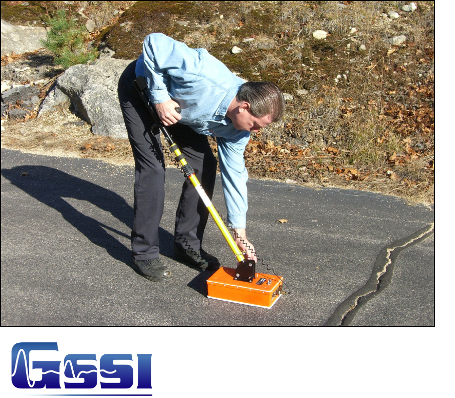
Thank you for purchasing a GSSI 3101A. The Model 3101A antenna is a high frequency antenna
that is designed for applications requiring very fine resolution and shallow depth penetration in a
variety of materials. Please take a moment to examine your shipment to familiarize yourself with
this manual. If you need assistance, GSSI technical support can be reached Monday-Friday, 8am-
5pm, US Eastern Time at (800) 524-3011, or at (603) 893-1109 (International). You can also
access technical support on the web at www.geophysical.com.
The Model 3101A can be used in continuous, survey wheel or static stacking modes. Please
consult your control unit documentation for instructions on configuring your system for data
collection modes.
System Setup - Standard Settings
Preset Settings:
System Run Mode: Survey Wheel (recommended) or Continuous
Range: 15 ns
Number of Gain Points: 3
Vertical Low Pass Filter: 2500 MHz
Vertical High Pass Filter: 225 MHz
Samples per Scan: 512
Bits per Sample: 16
Scans per Second: Set to 64 (increase to 120 when using survey wheel).
Deeper Profiling:
Setup Mode: Manual
System Run Mode: Survey Wheel (recommended) or Continuous
Range: 30 – 50 ns
Number of Gain Points: 3
Vertical Low Pass Filter: 2500 MHz
Vertical High Pass Filter: 225 MHz
Samples per Scan: 512
Bits per Sample: 16
Scans per Second: to 64 (increase to 120 when using survey wheel).
1
Geophysical Survey Systems, Inc. Model 3101A Series Antennas
System Settings and User Notes
Signal Position
Place the antenna on the ground and use the Automatic Signal Position selection. The system
will servo and place the direct coupling pulse at the top of the time range window.
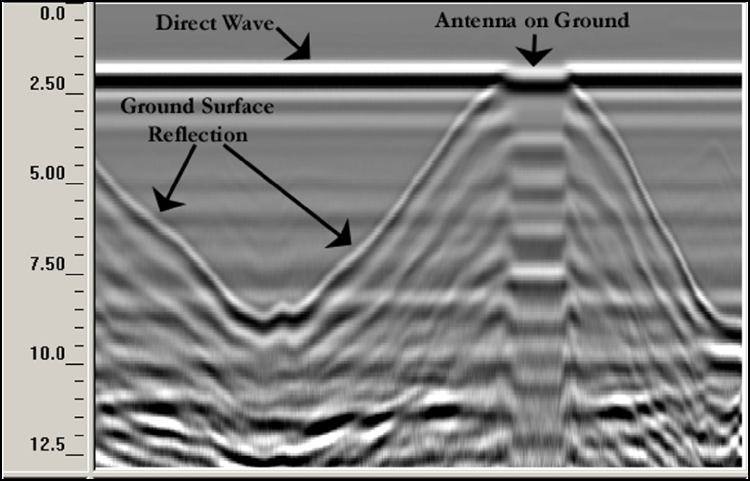
To test that you have the correct position, raise the antenna off the ground and you will observe
on your system that the antenna transmit pulse (direct wave) will separate from the reflection
from the ground. The higher that you raise the antenna, the further apart will be the two pulses.
Newer control units such as the SIR-3000 and the SIR-20 have advanced algorithms to locate the
surface position. If you would like to assure that the direct coupling pulse (time zero) is recorded,
the user should place the Signal Position Servo in the manual mode. The signal should then be
moved down in the time range window until the entire surface pulse is visible and there is some
‘dead time’ or flat trace visible above the direct coupling pulse in the time range window. If you
are using your 3101A with the SIR-3000, it will be necessary to set the SURFACE% to zero in
order to check the signal position. Please consult the SIR-3000 User’s Manual for additional
instructions on this point.
Gain Check
The surface pulse should be about 2/3 the width of the screen. If it is greater, reduce the Gains
manually. If the signal appears too small, you can manually increase the Gains, but the first gain
point should never exceed 10dB; the last gain point should not exceed 65dB.
2
Geophysical Survey Systems, Inc. Model 3101A Series Antennas
System Settings and User Notes
Using Your 3101A Antenna with a Survey Wheel
By using a survey wheel with your antenna you can more easily relocate targets to the survey
surface, and perform distance-based processing functions in RADAN without having to distance
normalize your data.
Survey wheels are available as a separate purchase. If you do not already own one, please contact
your GSSI Sales Representative to discuss the features and benefits of each type.
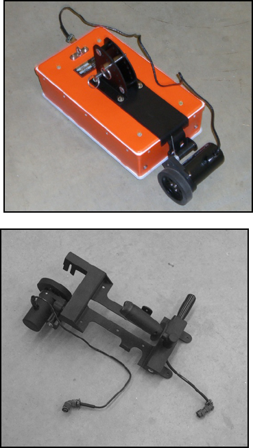
Model 611 (3 5/6” wheel)
Ticks/foot: 609.6
Ticks/meter: 2000
To attach the 611, simply undo the four screws holding
the antenna’s tow handle bracket and sandwich that 611
bracket plate between the antenna and the tow handle
bracket. Replace the four screws to secure.
Model 616 Minicart (4” wheel)
Ticks/foot: 486
Ticks/meter: 1590
To attach the 616, first undo the four screws holding
the antenna’s tow handle. Set the tow handle bracket
aside, but retain the four screws and washers. Attach
the 616 assembly to the 3101A with the four screws.
Connect the two leads from the 616 to the two small
connectors on the antenna.
The wheel of the Model 616 can be removed and
relocated on the cart to allow the antenna to scan with
the dipoles oriented 90 degrees to normal.
3
Geophysical Survey Systems, Inc. Model 3101A Series Antennas
System Settings and User Notes
4
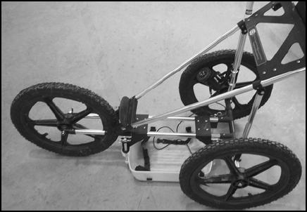
Model 62X Survey Cart
Ticks/foot: -487.8
Ticks/meter: -1583
The 3101A can be placed in the white plastic
antenna holder of the 62X cart for use on
rougher terrain or for large area surveys.
Note: Due to size limitations, a regular,
straight connector control cable will not fit the
3101A and the 62X cart. Be sure that you have
a control cable with a 90 degree connector on
the antenna end. GSSI makes a 2-meter control cable with a 90 degree connector that is designed
specifically to work with this cart.
Antenna Specifications
Center frequency: 900 MHz
Pulse duration: 1.1 ns
Depth of penetration: 0- 6 ft depending on dielectric permittivity
Size of sensor: 13×7.5×3.5 inches (33×20×8cm)
Weight of sensor: 7 lbs 4 oz. (3.4 kg)
Survey Wheel: Model 611 (3 5/6” wheel): 2000 ticks/meter
609.6 ticks/foot
Model 62X (three wheeled) Cart: -1583 ticks/meter
-487.8 ticks/foot
Model 616 cart (4.8” wheel): 1234.5 ticks/meter
486 ticks/foot