Geophysical Survey Systems 50400 50400 Antenna User Manual GENERAL FAXFORM
Geophysical Survey Systems, Inc. 50400 Antenna GENERAL FAXFORM
Users Manual
PendingFCCAppproval
Model 50400
System Settings and User Notes
The World Leader in
Subsurface Imaging™
Geophysical Survey Systems, Inc.
Tel 603.893.1109 • Fax 603.889.3984
sales@geophysical.com
www.geophysical.com
June, 2008
Copyright © 2008 Geophysical Survey Systems, Inc.
All rights reserved
including the right of reproduction
in whole or in part in any form
Published by Geophysical Survey Systems, Inc.
12 Industrial Way
Salem, New Hampshire 03079
Printed in the United States
GSSI, RADAN, and SIR are registered trademarks of Geophysical Survey Systems, Inc.
Geophysical Survey Systems, Inc. Model 5400 Antenna
System Settings and User Notes
Limited Warranty, Limitations Of Liability And Restrictions
Geophysical Survey Systems, Inc. hereinafter referred to as GSSI, warrants that for a period of
24 months from the delivery date to the original purchaser this product will be free from defects
in materials and workmanship. EXCEPT FOR THE FOREGOING LIMITED WARRANTY,
GSSI DISCLAIMS ALL WARRANTIES, EXPRESS OR IMPLIED, INCLUDING ANY
WARRANTY OF MERCHANTABILITY OR FITNESS FOR A PARTICULAR PURPOSE.
GSSI's obligation is limited to repairing or replacing parts or equipment which are returned to
GSSI, transportation and insurance pre-paid, without alteration or further damage, and which in
GSSI's judgment, were defective or became defective during normal use.
GSSI ASSUMES NO LIABILITY FOR ANY DIRECT, INDIRECT, SPECIAL, INCIDENTAL
OR CONSEQUENTIAL DAMAGES OR INJURIES CAUSED BY PROPER OR IMPROPER
OPERATION OF ITS EQUIPMENT, WHETHER OR NOT DEFECTIVE.
Before returning any equipment to GSSI, a Return Material Authorization (RMA) number must
be obtained. Please call the GSSI Customer Service Manager who will assign an RMA number.
Be sure to have the serial number of the unit available
MN30-266 Rev -
Geophysical Survey Systems, Inc. Model 5400 Antenna
System Settings and User Notes
FCC Notice (for U.S. Customers):
This device complies with part 15, class F of the FCC Rules:
Operation is subject to the following conditions:
1. This device many not cause harmful interference, and
2. This device must accept any interference received, Including interference that may cause
undesired operation
Warning: Changes or modifications to this unit not expressly approved by the party responsible for
compliance could void the user’s authority to operate the equipment.
Operation of this device is restricted to law enforcement, fire and rescue officials, scientific research
institutes, commercial mining companies, construction companies and private parties operating on behalf
of these groups. Operation by any other party is a violation of 47 U.S.C. § 301 and could subject the
operator to serious legal penalties.
Coordination Requirements
(a) UWB imaging systems require coordination through the FCC before the equipment may be used. The
operator shall comply with any constraints on equipment usage resulting from this coordination.
(b) The users of UWB imaging devices shall supply detailed operational areas to the FCC Office of
Engineering and Technology who shall coordinate this information with the Federal Government through
the National Telecommunications and Information Administration. The information provided by the
UWB operator shall include the name, address and other pertinent contact information of the user, the
desired geographical area of operation, and the FCC ID number and other nomenclature of the UWB
device. This material shall be submitted to the following address:
Frequency Coordination Branch, OET
Federal Communications Commission
445 12th Street, SW
Washington, D.C. 20554
ATTN: UWB Coordination
(d) Users of authorized, coordinated UWB systems may transfer them to other qualified users and to
different locations upon coordination of change of ownership or location to the FCC and coordination
with existing authorized operations.
(e) The NTIA/FCC coordination report shall include any needed constraints that apply to day-to-day
operations. Such constraints could specify prohibited areas of operations or areas located near authorized
radio stations for which additional coordination is required before operation of the UWB equipment. If
additional local coordination is required, a local coordination contact will be provided.
Notice: Use of this device as a wall imaging system is prohibited by FCC regulations.
MN30-266 Rev -

Geophysical Survey Systems, Inc. Model 5400 Antenna
System Settings and User Notes
For U.S. Customers
Ground Penetrating Radar Coordination Notice And Equipment Registration
Note: This form is only for Domestic United States users. The Federal Communications
Commission (FCC) requires that all users of GPR who purchased antennas after July 15th, 2002
register their equipment and areas of operation. If you have purchased any of the antennas listed
in question 6 after July 15th, 2002, you must fill out this form and fax or mail to the FCC.
Failure to do this is a violation of Federal law.
1. Date:
2. Company name:
3. Address:
4. Contact Information [contact name and phone number]:
5. Area Of Operation [state(s)]:
---Continued on next page.
MN30-266 Rev -
Geophysical Survey Systems, Inc. Model 5400 Antenna
System Settings and User Notes
6. Equipment Identification:
Brand Name: Geophysical Survey Systems, Inc.
Antenna Model No. (center frequency): CHECK all antennas being registered.
Model Frequency FCC ID
52600 2.6 GHz QF752600
4105 2.0 GHz QF74105
5100B 1.6 GHz QF75100
5101 1.0 GHz QF75101
4108F 1.0 GHz QF74108F
HandyScan 1.0 GHz QF7HANDYSCAN
3101D 900 MHz QF73101D
5103 400 MHz QF75103
5103A 400 MHz QF75103A
50400 400 MHz QF750400
TerraVision 400 MHz QF7TERRAVISION
5104 270 MHz QF75104
5106 200 MHz QF75106
7. Receipt Date Of Equipment:
Fax this form to the FCC at: 202-418-1944
Or
Mail to:
Frequency Coordination Branch, OET
Federal Communications Commission
445 12th Street, SW
Washington, D.C. 20554
ATTN: UWB Coordination
Do not send this information to GSSI.
MN30-266 Rev -

Geophysical Survey Systems, Inc. Model 5400 Antenna
System Settings and User Notes
Certificate
To Whom it may concern:
This is to certify that electromagnetic radiation emissions from transducers (antenna with
transmitting and receiving electronics) manufactured by Geophysical Survey Systems, Inc.
(GSSI) DO NOT constitute a safety or health hazard to operating personnel.
Emissions from GSSI transducers are below the 10mW/cm² (100W/m²) level specified by the
United States Occupational Safety and Health Administration (OSHA) regulations
Paragraph 1910.97 states:
"For normal environmental conditions and for incident electromagnetic frequencies from
100 MHz to 100 GHz, the radiation protection guide is
10 mW/cm² (milliwatt per square centimeter) as averaged over any possible 0.1 hour
period."
Emissions data using GPR SIR System-10, SIR-2, SIR-3, SIR-4, SIR-8, SIR-20, SIR-2000 and
SIR-3000 (at the standard Pulse Repetition Frequency of 100 KHz) with the antenna Models
listed and levels of Electromagnetic Radiation are specified herein:
Following is the average power density data at 5cm and wide band.
ANTENNA
(MHz) AVERAGE POWER DENSITY
(W/m2 @ 5 cm) OSHA SPEC.
(W/m2)
100 Less than 0.0001 100
200 Less than 0.0001 100
300 Less than 0.0001 100
270 Less than 0.0001 100
400 Less than 0.0001 100
500 Less than 0.0001 100
900 Less than 0.0001 100
1000 Less than 0.0001 100
1600 Less than 0.0001 100
2600 Less than 0.0001 100
GEOPHYSICAL SURVEY SYSTEMS, INC.
Alan E. Schutz
Engineering Director
MN30-266 Rev -
Geophysical Survey Systems, Inc. Model 5400 Antenna
System Settings and User Notes
This page intentionally left blank.
MN30-266 Rev -
Geophysical Survey Systems, Inc. Model 5400 Antenna
System Settings and User Notes
Table Of Contents
Model 5400 Antenna ...................................................................................................... 1
System Setup - Standard Settings .............................................................................. 1
Signal Position .................................................................................................... 2
Gain Check ......................................................................................................... 2
Specifications .............................................................................................................. 2
MN30-266 Rev -
Geophysical Survey Systems, Inc. Model 5400 Antenna
System Settings and User Notes
MN30-266 Rev -
Geophysical Survey Systems, Inc. Model 5400 Antenna
System Settings and User Notes
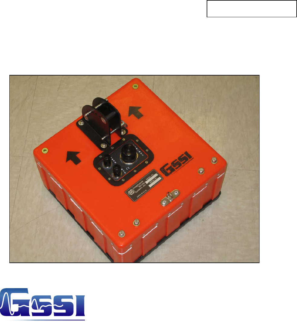
Model 50400 Antenna
The Model 50400 antenna has greatly improved resolution performance over previous GSSI
mid-frequency antennas, such as the Model 3105 (300 MHz). The Model 50400 can be used in
continuous, survey wheel or static stacking modes.
System Setup - Standard Settings
Preset Settings:
Range/Depth is approximately 2.5m (8 ft) assuming a dielectric constant of 9.
Setup Mode: Manual
System Run Mode: Survey Wheel (recommended) or Continuous
Range: 50 ns
Number of Gain Points: 5
Vertical Low Pass Filter: 800 MHz
Vertical High Pass Filter: 100 MHz
Samples per Scan: 512
Bits per Sample: 16
Scans per Second: Set to 120 (recommended).
Deep Profiling:
For approximately 5 m (16 ft) with a dielectric of 9.
Setup Mode: Manual
System Run Mode: Survey Wheel (recommended) or Continuous
Range: 100 ns
Number of Gain Points: 5
Vertical Low Pass Filter: 800 MHz
Vertical High Pass Filter: 100 MHz
Samples per Scan: 1024
Bits per Sample: 16
Scans per Second: Set to 120 (recommended).
MN30-266 Rev - 1
Geophysical Survey Systems, Inc. Model 5400 Antenna
System Settings and User Notes
MN30-266 Rev - 2
Signal Position
Place the antenna on the ground and use the Automatic Signal Position selection. The system
will servo and place the direct coupling pulse at the top of the time range window.
To test that you have the correct position, raise the antenna off the ground and you will observe
on your system that the antenna transmit pulse will separate from the reflection from the ground.
The higher that you raise the antenna, the further apart will be the two pulses.
To assure that the direct coupling pulse (time zero) is recorded the user should place the signal
Position servo in the manual mode. The signal should then be moved down in the time range
window until the entire surface pulse is visible and there is some ‘dead time’ or flat trace visible
above the direct coupling pulse in the time range window.
Gain Check
The surface pulse should be about 2/3 the width of the screen. If it is greater, reduce the Gains
manually. If the signal appears too small you can manually increase the Gains, but the first gain
point should never exceed 10dB, the last gain point should not exceed 65dB.
Specifications
Center frequency: 400 MHz
Pulse duration: 2.5 ns
Depth of penetration: 0-16 ft depending on dielectric permittivity
Size of sensor: 12×12×6.5 inches (30×30×17cm)
Weight of sensor: 14 lbs (6.4 kg)