Geophysical Survey Systems 5104 5104 Antenna User Manual GENERAL FAXFORM
Geophysical Survey Systems, Inc. 5104 Antenna GENERAL FAXFORM
Users Manual
Model 5104 Antenna
System Settings and User Notes
We Provide Complete Survey Solutions
Information People Can Use
Since 1970
Geophysical Survey Systems, Inc.
13 Klein Drive, P.O. Box 97
North Salem, NH 03073-0097
Phone: (603) 893-1109 / FAX: (603) 889-3984
www.geophysical.com
Manual MN30-192 Rev -
sales@geophysical.com

Geophysical Survey Systems, Inc. Model 5104 Antenna
System Settings and User Notes
Limited Warranty, Limitations Of Liability And Restrictions
Geophysical Survey Systems, Inc. hereinafter referred to as GSSI, warrants that, for a period of
12 months from the delivery date to the original purchaser, GSSI's products will be free from
defects in materials and workmanship. EXCEPT FOR THE FOREGOING LIMITED
WARRANTY, GSSI DISCLAIMS ALL WARRANTIES, EXPRESS OR IMPLIED,
INCLUDING ANY WARRANTY OF MERCHANTABILITY OR FITNESS FOR A
PARTICULAR PURPOSE. GSSI's obligation is limited to repairing or replacing parts or
equipment which are returned to GSSI, transportation and insurance pre-paid, without alteration
or further damage, and which in GSSI's judgment, were defective or became defective during
normal use.
GSSI ASSUMES NO LIABILITY FOR ANY DIRECT, INDIRECT, SPECIAL, INCIDENTAL
OR CONSEQUENTIAL DAMAGES OR INJURIES CAUSED BY PROPER OR IMPROPER
OPERATION OF ITS EQUIPMENT OR SOFTWARE, WHETHER OR NOT DEFECTIVE.
Before returning any equipment to GSSI, a Return Material Authorization (RMA) number must
be obtained. Please call the GSSI Customer Service Manager who will assign an RMA number.
Be sure to have the serial number of the unit available.
GSSI does not convey any license under its patent or other intellectual property rights or the
rights of others.
Note: Information in this manual is subject to change without notice. Please consult the
manual updates supplied with your system and contact GSSI with any additional
questions.
Copyright© 2004 Geophysical Survey Systems, Inc.
All rights reserved, including the right of reproduction in whole or in part in any form
Published by Geophysical Survey Systems, Inc.
13 Klein Drive
North Salem, New Hampshire 03073-0097
Printed in the United States
GSSI and SIR are registered trademarks of
Geophysical Survey Systems, Inc.
Manual MN30-240 Rev -
Geophysical Survey Systems, Inc. Model 5104 Antenna
System Settings and User Notes
FCC Notice (for U.S. Customers):
This device complies with part 15 of the FCC Rules:
Operation is subject to the following conditions:
1. This device many not cause harmful interference, and
2. This device must accept any interference received, Including interference that may cause
undesired operation
Warning: Changes or modifications to this unit not expressly approved by the party responsible for
compliance could void the user’s authority to operate the equipment.
Operation of this device is restricted to law enforcement, fire and rescue officials,
scientific research institutes, commercial mining companies, and construction
companies. Operation by any other party is a violation of 47 U.S.C. § 301 and could
subject the operator to serious legal penalties.
Coordination Requirements.
(a) UWB imaging systems require coordination through the FCC before the equipment may
be used. The operator shall comply with any constraints on equipment usage resulting from this
coordination.
(b) The users of UWB imaging devices shall supply detailed operational areas to the FCC
Office of Engineering and Technology who shall coordinate this information with the Federal
Government through the National Telecommunications and Information Administration. The
information provided by the UWB operator shall include the name, address and other pertinent
contact information of the user, the desired geographical area of operation, and the FCC ID number
and other nomenclature of the UWB device. This material shall be submitted to the following
address:
Frequency Coordination Branch., OET
Federal Communications Commission
445 12th Street, SW
Washington, D.C. 20554
ATTN: UWB Coordination
(d) Users of authorized, coordinated UWB systems may transfer them to other qualified
users and to different locations upon coordination of change of ownership or location to the FCC and
coordination with existing authorized operations.
(e) The NTIA/FCC coordination report shall include any needed constraints that apply to
day-to-day operations. Such constraints could specify prohibited areas of operations or areas
located near authorized radio stations for which additional coordination is required before operation
of the UWB equipment. If additional local coordination is required, a local coordination contact will be
provided.
(f) The coordination of routine UWB operations shall not take longer than 15 business days
from the receipt of the coordination request by NTIA. Special temporary operations may be handled
with an expedited turn-around time when circumstances warrant. The operation of UWB systems in
emergency situations involving the safety of life or property may occur without coordination provided
a notification procedure, similar to that contained in CFR47 Section 2.405(a)-(e), is followed by the
UWB equipment user.
NOTICE: Use of this device as a wall imaging system is prohibited by FCC regulations.
Manual MN30-192 Rev -
Geophysical Survey Systems, Inc. Model 5104 Antenna
System Settings and User Notes
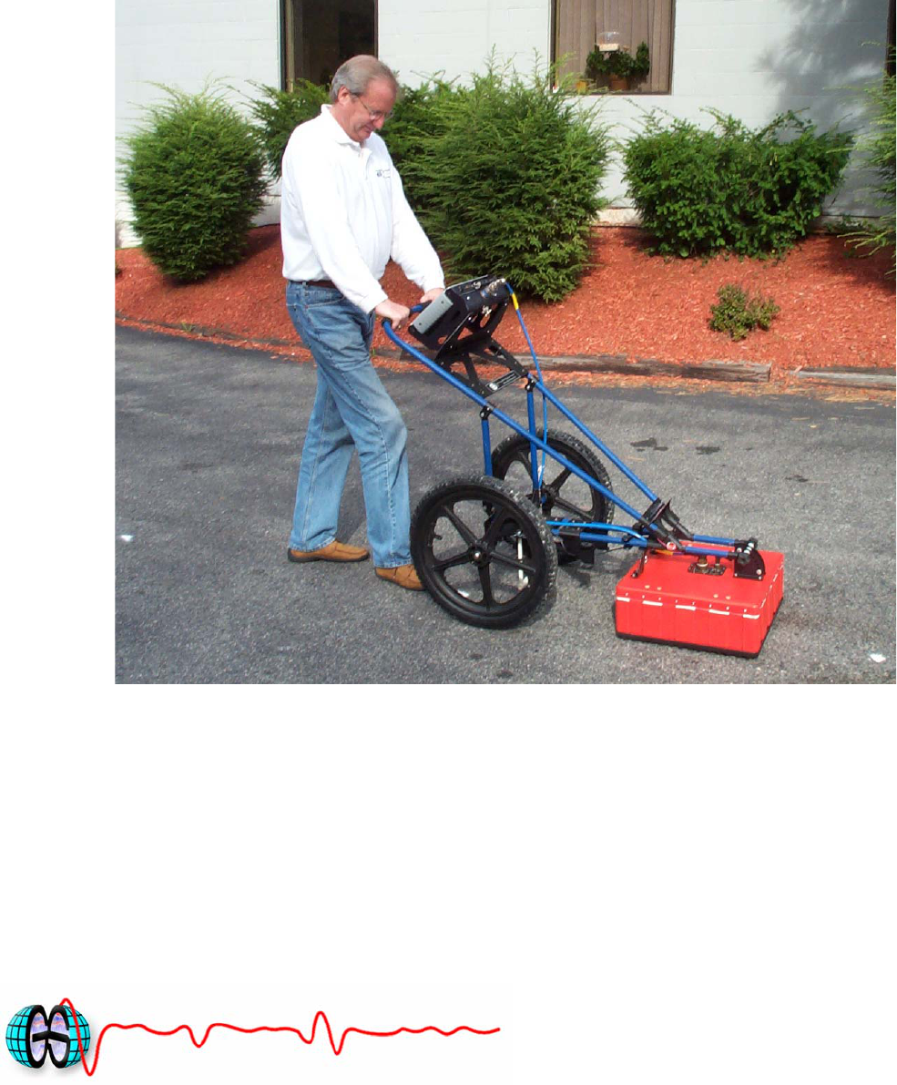
Model 5104 Antenna
The Model 5104 antenna has greatly improved resolution performance over previous GSSI
mid-frequency antennas, such as the Model 3105 (300 MHz). The Model 5104 can be used in
continuous, survey wheel or static stacking modes. The Model 5104 has a center frequency of
275 MHz when measured in air.
System Setup - Standard Settings
Shallow Profiling: Range/Depth is approximately 5m (15 ft) assuming a dielectric constant of
9.
Setup Mode: Manual
System Run Mode: Survey Wheel (recommended) or Continuous
Range: 100 ns
Number of Gain Points: 5
Vertical Low Pass Filter: 800 MHz
Vertical High Pass Filter: 30 MHz
Samples per Scan: 512
Bits per Sample: 16
Scans per Second: Set to maximum scan rate allowed by the SIR System used..
Deep Profiling: For approximately 8 m (25 ft) with a dielectric of 9.
Setup Mode: Manual
System Run Mode: Survey Wheel (recommended) or Continuous
Range: 175 ns
Number of Gain Points: 5
Vertical Low Pass Filter: 800 MHz
Vertical High Pass Filter: 30 MHz
Samples per Scan: 1024
Bits per Sample: 16
Scans per Second: Set to maximum scan rate allowed by the SIR System used..
Manual MN30-192 Rev - 1
Geophysical Survey Systems, Inc. Model 5104 Antenna
System Settings and User Notes
Signal Position
Place the antenna on the ground and use the Automatic Signal Position selection. The system
will servo and place the direct coupling pulse at the top of the time range window.
To test that you have the correct position, raise the antenna off the ground and you will observe
on your system that the antenna transmit pulse will separate from the reflection from the ground.
The higher that you raise the antenna, the further apart will be the two pulses.
To assure that the direct coupling pulse (time zero) is recorded the user should place the signal
Position servo in the manual mode. The signal should then be moved down in the time range
window until the entire surface pulse is visible and there is some ‘dead time’ or flat trace visible
above the direct coupling pulse in the time range window.
Gain Check
The surface pulse should be about 2/3 the width of the screen. If it is greater, reduce the Gains
manually. If the signal appears too small you can manually increase the Gains, but the first gain
point should never exceed 10dB, the last gain point should not exceed 65dB.
Specifications
Center frequency: 275 MHz
Pulse duration: 3.6 ns
Depth of penetration: 0-25 ft depending on dielectric permittivity
Size of sensor: 17.5×17.5×7.5 inches (44.5×44.5×19cm)
Weight of sensor: 19 lbs (8.6 kg)
Manual MN30-192 Rev - 2