Geophysical Survey Systems 62000 62000 User Manual GENERAL FAXFORM
Geophysical Survey Systems, Inc. 62000 GENERAL FAXFORM
Users Manual
Model 62000 Palm Antenna
System Settings and User Notes
The World Leader in
Subsurface Imaging™
Geophysical Survey Systems, Inc.
Tel 603.893.1109 • Fax 603.889.3984
sales@geophysical.com
www.geophysical.com
February, 2009
Copyright© 2009 Geophysical Survey Systems, Inc.
All rights reserved
including the right of reproduction
in whole or in part in any form
Published by Geophysical Survey Systems, Inc.
12 Industrial Way
Salem, New Hampshire 03079
Printed in the United States
GSSI, RADAN, and SIR are registered trademarks of Geophysical Survey Systems, Inc.
Geophysical Survey Systems, Inc. Model 62000 Palm Antenna
System Settings and User Notes
Limited Warranty, Limitations Of Liability And Restrictions
Geophysical Survey Systems, Inc. hereinafter referred to as GSSI, warrants that for a period of
24 months from the delivery date to the original purchaser this product will be free from defects
in materials and workmanship. EXCEPT FOR THE FOREGOING LIMITED WARRANTY,
GSSI DISCLAIMS ALL WARRANTIES, EXPRESS OR IMPLIED, INCLUDING ANY
WARRANTY OF MERCHANTABILITY OR FITNESS FOR A PARTICULAR PURPOSE.
GSSI's obligation is limited to repairing or replacing parts or equipment which are returned to
GSSI, transportation and insurance pre-paid, without alteration or further damage, and which in
GSSI's judgment, were defective or became defective during normal use.
GSSI ASSUMES NO LIABILITY FOR ANY DIRECT, INDIRECT, SPECIAL, INCIDENTAL
OR CONSEQUENTIAL DAMAGES OR INJURIES CAUSED BY PROPER OR IMPROPER
OPERATION OF ITS EQUIPMENT, WHETHER OR NOT DEFECTIVE.
Before returning any equipment to GSSI, a Return Material Authorization (RMA) number must
be obtained. Please call the GSSI Customer Service Manager who will assign an RMA number.
Be sure to have the serial number of the unit available
MN31-290 Rev -
Geophysical Survey Systems, Inc. Model 62000 Palm Antenna
System Settings and User Notes
FCC Notice (for U.S. Customers):
This device complies with part 15, class F of the FCC Rules:
Operation is subject to the following conditions:
1. This device many not cause harmful interference, and
2. This device must accept any interference received, including interference that may cause
undesired operation
Warning: Changes or modifications to this unit not expressly approved by the party responsible for
compliance could void the user’s authority to operate the equipment.
Operation of this device is restricted to law enforcement, fire and rescue officials, scientific research
institutes, commercial mining companies, construction companies and private parties operating on behalf
of these groups. Operation by any other party is a violation of 47 U.S.C. § 301 and could subject the
operator to serious legal penalties.
Coordination Requirements
(a) UWB imaging systems require coordination through the FCC before the equipment may be used. The
operator shall comply with any constraints on equipment usage resulting from this coordination.
(b) The users of UWB imaging devices shall supply detailed operational areas to the FCC Office of
Engineering and Technology who shall coordinate this information with the Federal Government through
the National Telecommunications and Information Administration. The information provided by the
UWB operator shall include the name, address and other pertinent contact information of the user, the
desired geographical area of operation, and the FCC ID number and other nomenclature of the UWB
device. This material shall be submitted to the following address:
Frequency Coordination Branch, OET
Federal Communications Commission
445 12th Street, SW
Washington, D.C. 20554
ATTN: UWB Coordination
(d) Users of authorized, coordinated UWB systems may transfer them to other qualified users and to
different locations upon coordination of change of ownership or location to the FCC and coordination
with existing authorized operations.
(e) The NTIA/FCC coordination report shall include any needed constraints that apply to day-to-day
operations. Such constraints could specify prohibited areas of operations or areas located near authorized
radio stations for which additional coordination is required before operation of the UWB equipment. If
additional local coordination is required, a local coordination contact will be provided.
Notice: Use of this device as a wall imaging system requires the use of a “deadman switch” as
supplied by GSSI.
MN31-290 Rev -

Geophysical Survey Systems, Inc. Model 62000 Palm Antenna
System Settings and User Notes
For U.S. Customers
Ground Penetrating Radar Coordination Notice And Equipment Registration
Note: This form is only for Domestic United States users. The Federal Communications
Commission (FCC) requires that all users of GPR who purchased antennas after July 15th, 2002
register their equipment and areas of operation. It is required that you fill out this form and fax or
mail to the FCC.
Failure to do this is a violation of Federal law.
1. Date:
2. Company name:
3. Address:
4. Contact Information [contact name and phone number]:
5. Area Of Operation [state(s)]:
---Continued on next page.
MN31-290 Rev -

Geophysical Survey Systems, Inc. Model 62000 Palm Antenna
System Settings and User Notes
6. Equipment Identification:
Brand Name: Geophysical Survey Systems, Inc.
Antenna Model No. (center frequency): List all antennas being registered.
Model Frequency
FCC ID (QF7 followed
by Model #)
7. Receipt Date Of Equipment:
Fax this form to the FCC at: 202-418-1944
Or
Mail to:
Frequency Coordination Branch, OET
Federal Communications Commission
445 12th Street, SW
Washington, D.C. 20554
ATTN: UWB Coordination
Do not send this information to GSSI.
MN31-290 Rev -
Geophysical Survey Systems, Inc. Model 62000 Palm Antenna
System Settings and User Notes
Table of Contents
Model 62000 Palm Antenna .......................................................................................... 1
System Setup - Standard Settings .............................................................................. 1
“Deadman” Switch Operation (IMPORTANT!) .................................................... 1
Signal Position .................................................................................................... 2
Gain Check ......................................................................................................... 3
The Marker Switch ............................................................................................. 3
Integrated Survey Wheel .................................................................................... 3
To change the wheel position ............................................................................. 3
Antenna Specifications ............................................................................................... 5
MN31-290 Rev -
Geophysical Survey Systems, Inc. Model 62000 Palm Antenna
System Settings and User Notes
MN31-290 Rev -
Geophysical Survey Systems, Inc. Model 62000 Palm Antenna
System Settings and User Notes
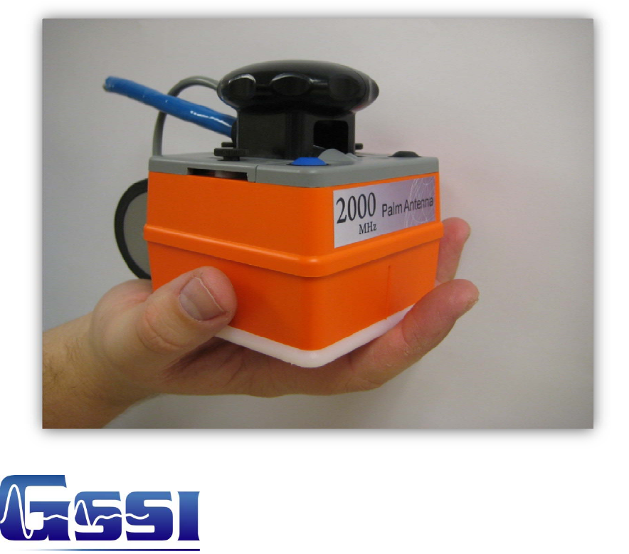
Model 62000 Palm Antenna
Thank you for purchasing the Model 62000, 2000 MHz Palm Antenna. The Palm Antenna
combines exceptionally fine resolution in a small package. Its small size will help the concrete
scanning professional to get into areas which are too tight for conventional antennas.
The Palm antenna incorporates an integrated survey wheel which can change position and allow
you to use the antenna in a cross-polarized configuration to aid in the detection of non-metallic
objects. The Palm antenna also comes with an integrated control cable with a length of 7 m
(22.75 feet). There is also an antenna safety attachment point 1.5 m (5 feet) from the antenna. If
you are working high above the ground, GSSI recommends attaching the safety point to your belt
so that the antenna will not be damaged if you drop it.
The Palm antenna is backward compatible with previous GSSI SIR Systems.
Note: The indented vertical lines on the sides of the antenna housing denote the center of the
antenna. When marking locations on the concrete, this is the reference point on the antenna to
mark.
System Setup - Standard Settings
Note: You must follow these setup instructions exactly to use the Model 62000 antenna.
Positioning of the signal will be the last step in the process.
Setup Mode: Manual
System Run Mode: Survey Wheel (recommended) or Continuous
Range: 5-8 ns
Scans/foot (meter): 90 (300)
Number of Gain Points: 4, Auto Gain
Vertical Low Pass FIR Filter: 4000 MHz
Vertical High Pass FIR Filter: 500 MHz
Vertical High Pass IIR Filter: 10 MHz
Samples per Scan: 256 or 512
Bits per Sample: 16
Scans per Second: Set to the maximum scan rate allowed by the SIR System used
“Deadman” Switch Operation (IMPORTANT!)
In order to comply with various emissions standards imposed by various governments, the Palm
antenna incorporates a “Deadman” switch which will turn off the transmitter when the operator
is not using the antenna. The Palm antenna incorporates two “Deadman” devices: the blue button
on the top of the antenna housing and the survey wheel. When neither of these is used, the
antenna will shut off after 10 seconds. It will resume instantly if the survey wheel is moved or
the button is pressed.
MN31-290 Rev - 1
Geophysical Survey Systems, Inc. Model 62000 Palm Antenna
System Settings and User Notes
You must hold down the Blue button whenever the SIR-3000 System is doing the following:
1. Booting from the initial logo screen into your chosen data collection application
(TerraSIRch, ConcreteScan, Quick3D)
2. Changing any collection parameter (Depth, Range, Filters, Position, Dielectric, Sampling
Density, Gains).
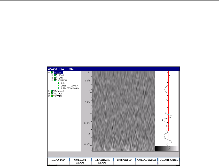
If the “Deadman” switch is not held down during any of the above, your screen will look like the
image below. If that happens, hold down your “Deadman” switch and change your Range/Depth.
The antenna will re-initialize and you should see horizontal bands scrolling across the screen.
This process may take several seconds.
Figure 1: “Deadman” switch not held down, transmitter turned off.
Once you begin to collect data, the survey wheel will act as the “Deadman” switch. You can let
go of the blue button and as long as the wheel is turning, the transmitter will stay on.
Signal Position
1. Place the antenna on the concrete floor and use the Automatic Signal Position selection.
• If you are in ConcreteScan, this is done by pressing the Run/Stop button twice.
• If you are in TerraSIRch, go to Collect>Position> and toggle from Auto to Manual and then
back to Auto.
• You may need to try this 2 to 3 times to get the system to lock on to the surface pulse. If
after 3 tries the surface reflection is not in the signal window, point the antenna into the air
and again try the Automatic Position.
2. To test that you have the correct position, raise the antenna off the ground and you will
observe on your system that the antenna transmit waveform will separate from the
MN31-290 Rev - 2
Geophysical Survey Systems, Inc. Model 62000 Palm Antenna
System Settings and User Notes
reflection from the ground. The higher that you raise the antenna, the further apart will be
the two waveforms.
Gain Check
GSSI recommends allowing the SIR System to automatically set gain levels. Place the antenna in
contact with the concrete so that the SIR System sets values which are appropriate for the
material. Be sure to hold down the “Deadman” switch while re-initializing the gains.
The Marker Switch
The black button on the top of the antenna housing is a remote marker switch. Pushing this while
collecting data will put a user mark in the data. This is useful for situations when you want to
record the location of a surface feature or other important item in the data.
Integrated Survey Wheel
Your Palm antenna incorporates a survey wheel for collecting data in Distance (Survey Wheel)
mode. While it is still possible to collect Continuous (Time based) data with the Palm antenna,
the survey wheel cannot be removed from the antenna.
GSSI recommend calibrating the survey wheel by following the instructions presented in your
SIR-System manual. For convenience the calibration value is approximately 1697 counts/foot
(5568/m). Note that this value is subject to change and you should calibrate your own survey
wheel for accuracy.
The survey wheel can be moved to the side of the antenna in order to collect data with the
antenna elements in the cross-polarized configuration. Please see the GSSI Handbook for
RADAR Inspection of Concrete for a discussion of the benefits of this technique.
To change the wheel position
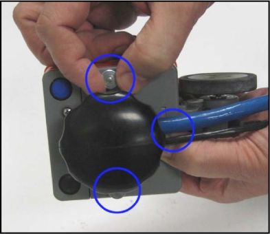
1.
Remove the three thumb screws (blue enclosures in Figure 2) securing the survey wheel
attachment plate.
Figure 2: Remove thumb screws.
MN31-290 Rev - 3
Geophysical Survey Systems, Inc. Model 62000 Palm Antenna
System Settings and User Notes
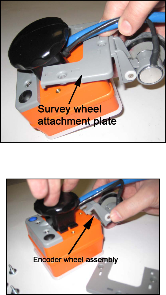
2. Lift the gray, plastic survey wheel attachment plate off of the antenna and set aside
(Figure 3).
Figure 3: Remove attachment plate.
3. Swing the encoder wheel assembly to one side of the antenna (Figure 4). The side you
choose has no effect on the data.
Figure 4: Reposition wheel assembly.
MN31-290 Rev - 4
Geophysical Survey Systems, Inc. Model 62000 Palm Antenna
System Settings and User Notes
MN31-290 Rev - 5
4. Secure the wheel assembly to the antenna by screwing the attachment plate back to the
antenna. Note that the two tabs on the encoder wheel assembly will need to go into the two
cutouts on the attachment plate. (Figure 5).
Figure 5: Re-secure the encoder assembly.
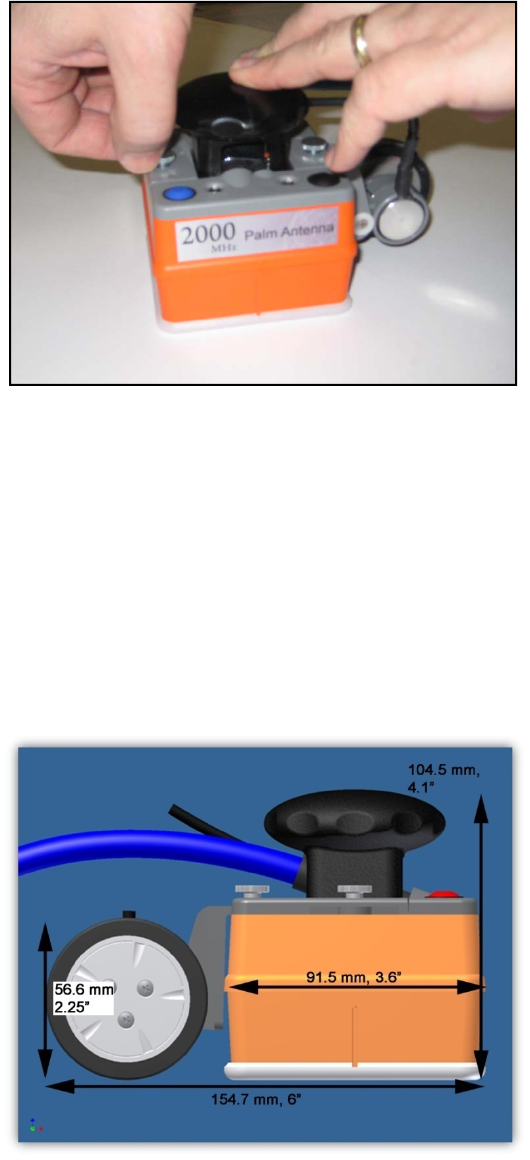
Antenna Specifications
Center frequency: 2000 MHz
Weight: 0.5 kg (1.1 lbs) without control cable
1.5 kg (3.3 lbs) with control cable
Control cable length: 7 meters (22.75 feet)
Pulse duration: 0.5 ns
Penetration Depth: 0-0.3 meters (0-12 inches) depending on concrete conditions