Geophysical Survey Systems INTERRAGATOR INTERRAGATOR User Manual interra2 o2 01
Geophysical Survey Systems, Inc. INTERRAGATOR interra2 o2 01
Contents
- 1. Manual
- 2. Manual addendum
Manual

Vermeer®
Interragator® II
Ground Penetrating Radar (GPR) System
ACS
Interragator_II_o2_01
Serial No. 178 -
Order No. 105400T23
Cabled No. 105400T24
Operator’s Manual
This device complies with part 15 of the FCC Rules:
Operation is subject to the following conditions:
1. This device many not cause harmful interference, and
2. This device must accept any interference received, Including interference that may cause undesired operation
Warning: Changes or modifications to this unit not expressly approved by the party responsible for compliance could void the user’s authority
to operate the equipment.
Operation of this device is restricted to law enforcement, fire and rescue officials, scientific research institutes, commercial mining
companies, and construction companies. Operation by any other party is a violation of 47 U.S.C. § 301 and could subject the
operator to serious legal penalties.
Coordination Requirements.
(a) UWB imaging systems require coordination through the FCC before the equipment may be used. The operator shall comply with any
constraints on equipment usage resulting from this coordination.
(b) The users of UWB imaging devices shall supply detailed operational areas to the FCC Office of Engineering and Technology who
shall coordinate this information with the Federal Government through the National Telecommunications and Information Administration. The
information provided by the UWB operator shall include the name, address and other pertinent contact information of the user, the desired
geographical area of operation, and the FCC ID number and other nomenclature of the UWB device. This material shall be submitted to the
following address:
Frequency Coordination Branch., OET
Federal Communications Commission
445 12th Street, SW
Washington, D.C. 20554
ATTN: UWB Coordination
(d) Users of authorized, coordinated UWB systems may transfer them to other qualified users and to different locations upon coordination
of change of ownership or location to the FCC and coordination with existing authorized operations.
(e) The NTIA/FCC coordination report shall include any needed constraints that apply to day-to-day operations. Such constraints could
specify prohibited areas of operations or areas located near authorized radio stations for which additional coordination is required before operation
of the UWB equipment. If additional local coordination is required, a local coordination contact will be prov ided.
(f) The coordination of routine UWB operations shall not take longer than 15 business days from the receipt of the coordination request by
NTIA. Special temporary operations may be handled with an expedited turn-around time when circumstances warrant. The operation of UWB
systems in emergency situations involving the safety of life or property may occur without coordination provided a notification procedure, similar to
that contained in CFR47 Section 2.405(a)-(e), is followed by the UWB equipment user.

-2 Interragator II GPR System
INTRODUCTION
This manual contains operation instructions for the Interragator II Ground Penetrating Radar System. The instructions,
illustrations, and specifications in this manual are based on the latest information available at time of publication. Your system
may have product improvements and options not yet contained in this manual.
To provide a better view, certain photographs or illustrations in this manual may show the GPR system partially assembled.
Never operate the system in this condition. Keep all shields in place.
Do not attempt any maintenance on the GPR system. If you encounter a problem that you do not understand or cannot solve,
contact your Vermeer dealer.
A copy of this manual is supplied with each system. Keep this manual with the GPR system and available for reference at all
times. Additional copies are available through your dealer. When ordering additional manuals, use the order number listed on the
front cover and the quantity needed.
Vermeer Manufacturing Company reserves the right to make changes at any time without notice or obligation
VERMEER®, VERMEER® Logo, INTERRAGATOR®, and ATLAS BORE PLANNER® are trademarks of Vermeer Manufacturing Company.
PANASONIC TOUGHBOOK is a trademark of Matsushita Electric Industrial Co. Ltd.
MICROSOFT is a trademark of Microsoft Corp.
SMART TWO + is a trademark of Cadex Electronics Inc.
SEIKO is a trademark of Seiko Instruments, Inc.
RADAN NT is a trademark of Geophysical Survey Systems, Inc.
LAPLINK is a trademark of Traveling Software, Inc.
This Used Equipment Registration form must be completely filled out and returned to Vermeer
Manufacturing Company. This will enable Vermeer to send you safety/product information if
necessary. Type or legibly print in English. Send to Vermeer Mfg Co, Attn: Customer Data
Center, PO Box 200, Pella, IA 50219, USA. If the card has been removed, call 641-628-3141
or 800-829-0051. Be prepared to supply the model & serial number of your machine.
Model SN
Vermeer Manufacturing Company
Used Industrial Equipment Registration Form
Customer Type Information: (Which of the following best describes you as a customer?)
New Owner Information: (Please Print and Complete All Fields)
Former Owner Information: Attachment Information
❏ Check to request OPERATOR’S MANUAL 18 Model: 19 Serial No.:
1a. Customer Type (check one):
(also check 1b/1c for lined types*)
❏ A. City/County/State ‹ ‹ ‹
❏ B. Federal/Military
❏ C. Rental Center
❏ D. Golf Course
❏ E. Contractor ‹ ‹ ‹ ‹ ‹
❏ F. Utility Company ‹ ‹ ‹ ‹
❏ G. Nursery or Tree Growing
1b. * If City/County/State, indicate primary work performed (Please check one box)
❏ a. Electric ❏ c. Highway Department ❏ e. Parks and Recreation
❏ b. Streets and Sanitation❏ d. Water / Sewer ❏ f. Landfill ❏ g. Other
---------------------------------------------------------------------------------------------------
1c. * If Contractor or Utility, indicate primary work performed (Please check one box)
❏ a. Electric ❏ j. Pipeline ❏ n. Golf Course Construction❏ r. Land Cleaning
❏ d. Water/Sewer ❏ k. Irrigation ❏. Roads ❏ s. General Trenching
❏ h. Landscaping ❏ l. Tree Service ❏ p. General Construction ❏ t. Boring
❏ i. Telephone ❏ m. Gas ❏ q. Waste Processing/Landfill❏ u. CATV o v. Other
2 Contact Name: 12 Title: 21 Purchase Date:
3 Business Name: 13 National/Global Account? ❏ Yes
4 Parent Company: 14 Business Phone: ( )
5 Address 1: 15 Home Phone: ( )
6 Address 2: 16 Fax: ( )
7 City: 8 County: 17 E-mail:
9 State (Province)/Region: 10 Postal Code: 11 Country:
Name: 25 Attachment #1:
Address: 26 Att #1 Serial #:
27 Attachment #2:
City: State/Region: 28 Att #2 Serial #:
Postal Code: Country: 29 Trailer & Serial #:


Interragator II GPR System -5
SERVICE
Do not attempt to service this system without the assistance of a Vermeer dealer. This is a complex machine which often involves
complex service procedures.
There are also many components which are not user-serviceable. Do not attempt any service which you do not fully understand,
nor any service that you cannot do accurately and safely without proper tools and equipment.
If you encounter a problem that you do not understand or cannot solve, contact your Vermeer dealer.
VERMEER NEW INDUSTRIAL EQUIPMENT LIMITED WARRANTY
(EFFECTIVE NOVEMBER 1, 1998)
WARRANTY PERIOD 12 Months / 1000 Hours
Vermeer Mfg. Co. (hereinafter “Vermeer”) warrants each new Industrial product of Vermeer’s manufacture to be free from defects in
material and workmanship, under normal use and service for one (1) full year after initial purchase/retail sale or 1000 operating
hours, whichever occurs first. This Limited Warranty shall apply only to complete machines of Vermeer’s manufacture, parts are
covered by a separate Limited Warranty. EQUIPMENT AND ACCESSORIES NOT OF VERMEER’S MANUFACTURE ARE
WARRANTED ONLY TO THE EXTENT OF THE ORIGINAL MANUFACTURER’S WARRANTY AND SUBJECT TO
THEIR ALLOWANCE TO VERMEER ONLY IF FOUND TO BE DEFECTIVE BY SUCH MANUFACTURER.
EXTENDED WARRANTY OPTIONS ARE AVAILABLE FOR PURCHASE.
WARRANTY TERMS
During the Limited Warranty period specified above, any defect in material or workmanship in any warranted item of Vermeer
Industrial Equipment not excluded below shall be repaired or replaced at Vermeer’s option without charge by any authorized
independent Vermeer dealer. The warranty repair or replacement must be made by a Vermeer independent authorized dealer at the
dealer’s location. Vermeer will pay for replacement parts and such authorized dealer’s labor in accordance with Vermeer’s labor
reimbursement policy. Vermeer reserves the right to supply remanufactured replacement parts as it deems appropriate.

-6 Interragator II GPR System
RETAIL PURCHASER RESPONSIBILITY:
This Limited Warranty requires proper maintenance and periodic inspections of the Industrial Equipment as indicated in the
Operator’s Manual furnished with each new Industrial Equipment. The cost of routine or required maintenance and services is the
responsibility of the retail purchaser. The retail purchaser is required to keep documented evidence that these services were
performed.
This Vermeer New Industrial Equipment Limited Warranty may be subject to cancellation if the above requirements are not
performed.
Vermeer Industrial Equipment with known failed or defective parts must be immediately removed from service.
EXCLUSIONS AND LIMITATIONS
The warranties contained herein shall NOT APPLY TO:
1) Any defect which was caused (in Vermeer’s sole judgment) by other than normal use and service of the Industrial Equipment,
or by any of the following; (i) accident (ii) misuse or negligence (iii) overloading (iv) lack of reasonable and proper maintenance
(v) improper repair or installation (vi) unsuitable storage (vii) non-Vermeer approved alteration or modification (viii) natural
calamities (ix) vandalism (x) parts or accessories installed on Industrial Equipment which were not manufactured or installed
by Vermeer authorized dealers (xi) the elements (xii) collision or other accident.
2) Any Industrial Equipment whose identification numbers or marks have been altered or removed or whose hourmeter has been
altered or tampered with.
3) Any Industrial Equipment which any of the required or recommended periodic inspection or services have been performed
using parts not manufactured or supplied by Vermeer or meeting Vermeer Specifications including, but without limitation,
engine tune-up parts, engine oil filters, air filters, hydraulic oil filters, and fuel filters.
4) New Industrial Equipment delivered to the retail purchaser in which the warranty registration has not been completed and
returned to Vermeer within ten (10) days from the date of purchase.
5) Any defect which was caused (in Vermeer’s sole judgment) by operation of the Industrial Equipment not abiding by standard
operating procedures outlined in the Operator’s Manual.
6) Engine, battery, and tire Limited Warranties and support are the responsibility of the respective product’s
manufacturer.

Interragator II GPR System -7
7) Transportation costs, if any, of transporting to the Vermeer dealer.
8) The travel time of the Vermeer dealer’s service personnel to make a repair on the retail purchaser’s site or other location.
9) In no event shall Vermeer’s liability exceed the purchase price of the product.
10) Vermeer shall not be liable to any person under any circumstances for any incidental or consequential damages (including but
not limited to, loss of profits, out of service time) occurring for any reason at any time.
11) Diagnostic and overtime labor premiums are not covered under this Limited Warranty Policy.
12) Depreciation damage caused by normal wear, lack of reasonable and proper maintenance, failure to follow
operating instructions, misuse, lack of proper protection during storage.
13) Accessory systems and electronics not of Vermeer’s manufacture are warranted only to the extent of such manufacturer’s
respective Limited Warranty, if any.
14) Down hole toolage is not covered under this warranty.
15) Wear items which are listed by product group below:
ENVIRONMENTAL: Belts, Chain, Wear Strips, Cutter Wheels, Pockets, Knives, Service Items, Shear Bar/Bed Knife, Sprockets,
Brake Pads, Bolts/Torqued Parts, Wear Blocks, Hammermill Bearings, Discharge Conveyor Belts, Hoses, Clutches, Clutch
Components, Hammers, Teeth, Blades, Oil Filters, Fuel Filters, Screens, Rods, Rotor Plates, Rollers
TRACK: Digging Chain, Base Plates, Cups, End Idler, Wear Plates/Track Frames, Flashings, Pins At Pivot Points, Sprockets, Teeth,
Boom Wear Items, Track Chain, Conveyor Belts, Plastic Wear Strips, Pivot Rings
TRENCHLESS: Fan Belts, Lights On Light Kits, Wear Bars, Rollers, Tooling, Valve Seats, Track Guides, Track Chain, Track
Sprockets, Drive Chuck, Earth Stakes, Water Hoses, Leaf Chain, Wear Blocks, Clamping Vise Parts, Packing Assemblies, Jaws,
Water Swivels, Rod Loader Parts, Track Pads, Track Idlers, Rod
RUBBER TIRE: Bearings, End Rollers, Belts, Pins, Trench Cleaner, Tires, Bucket, Brake Pads, Clutches, Track Sprockets,
Sprockets, Chains, Bushings, Booms, Rubber Shielding, Bucket Teeth, Plow Blades, Rock Wheel Teeth, Augers, Track Idlers
PARTS WARRANTY: Parts replaced in the warranty period will receive the balance of the first year New Industrial Equipment
Limited Warranty, during the first (12) months or 1000 hours whichever comes first. Replacement parts after the original machine

-8 Interragator II GPR System
warranty, are warranted to be free from defects of material for ninety (90) days or the part will be repaired or replaced, without labor
coverage for removal or reinstallation.
EXCLUSIONS OF WARRANTIES: EXCEPT FOR THE WARRANTIES EXPRESSLY AND SPECIFICALLY MADE HEREIN,
VERMEER MAKES NO OTHER WARRANTIES, AND ANY POSSIBLE LIABILITY OF VERMEER HEREUNDER IS IN LIEU OF
ALL OTHER WARRANTIES, EXPRESS, IMPLIED, OR STATUTORY, INCLUDING, BUT NOT LIMITED TO, ANY WARRANTIES
OF MERCHANTABILITY OR FITNESS FOR A PARTICULAR PURPOSE. VERMEER RESERVES THE RIGHT TO MODIFY,
ALTER AND IMPROVE ANY PRODUCT WITHOUT INCURRING ANY OBLIGATION TO REPLACE ANY PRODUCT
PREVIOUSLY SOLD WITH SUCH MODIFICATION. NO PERSON IS AUTHORIZED TO GIVE ANY OTHER WARRANTY, OR TO
ASSUME ANY ADDITIONAL OBLIGATION ON VERMEER’S BEHALF.
MANUFACTURED BY:
VERMEER MANUFACTURING COMPANY
Copyright © 2002
1210 Vermeer Road East, P.O. Box 200
Pella, Iowa 50219-0200
All rights reserved.

Interragator II GPR System -9
PATENTS This machine may be covered by one or more of the following patents:
(Other U.S. and foreign patents pending.)
CA D 79,593 US Pat. #5,074,063 US Pat. #5,611,496 US Pat. #5,950,942 US Pat. #6,360,830
CC 95 914 404.5 US Pat. #5,088,532 US Pat. #5,657,803 US Pat. #6,014,996 US Pat. #6,367,564
CC ZL96195734.4 US Pat. #5,205,181 US Pat. #5,659,985 US Pat. #6,050,350 US Pat. #6,374,928
DE 696 11 846 US Pat. #5,219,380 US Pat. #5,687,807 US Pat. #6,109,367 US Pat. #6,382,330
DE Des. 96 006 85.4 US Pat. #5,237,888 US Pat. #5,692,548 US Pat. #6,119,376 US Pat. #6,389,360
EP 772,543 US Pat. #5,291,964 US Pat. #5,692,549 US Pat. #6,138,932
EP 885,343 US Pat. #5,394,583 US Pat. #5,704,142 US Pat. #6,154,987
GB 2,053,636 US Pat. #5,507,441 US Pat. #5,720,354 US Pat. #6,161,630
HK 1015859 US Pat. #5,509,220 US Pat. #5,746,278 US Pat. #6,195,922
RU 2,141,907 US Pat. #5,544,055 US Pat. #5,768,811 US Pat. #6,247,544
RU 2,158,952 US Pat. #5,553,407 US Pat. #5,778,991 US Pat. #6,289,997
RU 2,163,963 US Pat. #5,556,253 US Pat. #5,819,859 US Pat. #6,290,155
RU 2,175,368 US Pat. #5,574,642 US Pat. #5,845,689 US Pat. #6,308,787
US Des. Pat. #308,682 US Pat. #5,588,474 US Pat. #5,904,210 US Pat. #6,315,062
US Des. Pat. #396,837 US Pat. #5,590,041 US Pat. #5,941,320 US Pat. #6,332,502
US Pat. #4,848,423 US Pat. #5,607,280 US Pat. #5,944,121 US Pat. #6,357,537
This machine may be covered by one or more of the following licensed patents:
US Pat. #4,694,913 US Pat. #4,867,255 US Pat. #5,148,880
US Pat. #4,858,704 US Pat. #4,953,638 US Pat. #5,799,740
This page intentionally left blank.
Interragator II GPR System Receiving and Delivery Report i
Receiving and Delivery Report
DEALER PREP
Check or perform the following:
General
___ Check that all loose items are included with the system.
___ Ensure Operator’s Manual is with the system.
___ Check for shipping damage or shortage.
___ Check decal condition.
___ Check all phases of operation.
___ Complete “Dealer/Customer Information,” page -ii
___ Complete “Identification Number - Record,” page -ii.
ii Receiving and Delivery Report Interragator II GPR System
DEALER/CUSTOMER INFORMATION
IDENTIFICATION NUMBER - RECORD
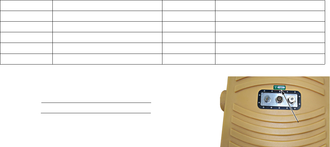
Antenna
Model Number
Serial Number
dealer: owner:
address: address:
city: city:
state/province: state/province:
zip/postal code: zip/postal code:
country: country:

Interragator II GPR System Receiving and Delivery Report iii
Thermal Printer
Model Number
Serial Number
Interragator II GPR System
Model Number
Serial Number
iv Receiving and Delivery Report Interragator II GPR System
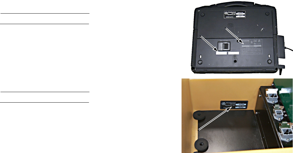
Panasonic Toughbook Computer
Model Number
Serial Number
Cart
Model Number
Serial Number
DELIVERY
Check, perform, and review the following with the customer:
___ overview of how the system works
___ system safety

Interragator II GPR System Bill of Materials v
Bill of Materials
MATERIALS LIST
Item Number Description of Part Required
296250373 Interragator II GPR System (GPR200) w/ 300 MHz Antenna, Deployment Cart, and Toughbook Computer 1
286810001 Interragator II 300 MHz Antenna 1
286811001 Antenna Housing 1
296268529 Antenna Housing w/ Skid Plate Runners 1
286863001 Antenna Mounting Knobs (Locating Boss) 2
296250359 Skid Plate Runners Kit, plastic 1
286812001 Interragator II Deployment Cart Assembly 1
296268530 Deployment Cart Housing 1
296268531 Lower Control Cable 1
296268532 Battery/Connector Panel w/ 3-pin connectors 1
296268533 Control Cable Connector Plate, metal 1
286817001 Wheels; 20″ diameter, solid core 2
286818001 Survey Wheel Encoder 1
296268534 Antenna Clamp (right side) 1
296268535 Antenna Clamp (left side) 1
286864001 Antenna Mounting Bracket, metal 2
286820001 Antenna Clamp Knobs 2
296250374 Battery Bracket in Storage Compartment 1
296250434 Counterweight, metal w/ Vermeer decal 1

vi Bill of Materials Interragator II GPR System
142410001 Operator's Manual Box 1
296250436 Cart Handle Arms, fiberglass 2
296250437 Plunger Pins (for cart handle adjustment) 2
296268537 Storage Compartment Cover w/ hinge 1
286813001 Deployment Cart Handle 1
296250438 Handle Pins 2
286815001 Cable Ties, Velcro 4
296268541 Computer Mounting Plate Assembly incl. all brackets, cables, & electronic components 1
296268542 Computer Mounting Plate 1
296250363 DC-DC Converter for Toughbook computer incl. cables 1
296268543 DC-DC Converter Brackets 2
296268544 Front Retainer Bracket (left side) 1
296268545 Front Retainer Bracket (right side) 1
296268546 Thumb Screws for front retainer brackets 2
296268547 Computer Mounting Plate Stops (set of 2) 1
296268548 Support Brackets for mounting plate w/ screws (set of 2) 1
296268549 Interface Box w/ power & comm lights; incl. ethernet, power, and GPR data cabling 1
296268550 Ethernet Connector Cover w/ gasket & thumb screw 1
296268553 Panasonic CF-28 Toughbook Computer (Model # CF-28MCFGZDM) 1
296268554 CD-ROM Drive, Read-Write Capabilities 1
296250291 AC Power Supply 1
296268555 Battery for CF-28 Toughbook 1
296250366 Stylus Pen 3
Item Number Description of Part Required

Interragator II GPR System Bill of Materials vii
296268556 Sunshade for CF-28 Toughbook 1
296250371 12 VDC “Smart” Battery 2
278519001 Battery Charger 1
296268558 Battery only; without wiring harness or pouch 1
296250441 Battery Wiring Harness w/ “smart” circuit 1
286869001 Auto Adapter / Inverter (400W, 2 outlet) 1
296268559 Battery Replacement Kit (battery only and inverter) 1
296250442 Connector (2-pin Hirschman, male) 1
296268560 Connector (3-pin Hirschman, male) 1
296268561 Adapter Cable for battery (5-pin to 3-pin) 1
296268562 Adapter Cable for battery (3-pin to 5-pin) 1
286861001 Seiko Thermal Printer Package (optional) 1
286829001 Seiko Thermal Printer 1
286830001 Seiko Printer Paper (box of 5 rolls) 1
286831001 Seiko AC Power Supply and cord 1
286832001 Seiko Serial Printer Cable 1
296268563 Printer Case w/ paper holder, canvas 1
286865001 Radan to Bitmap (RAD2BMP) Software (optional) 1
286833001 RADAN Data Processing Software - Main Module Only (optional) 1
296250444 RADAN Data Processing Software - Utility Locating Module (optional); must have Main Module also 1
296268567 Interragator II Operator's Manual (untethered); for systems with the Panasonic CF-28 Toughbook 1
296268568 Interragator II Operator's Manual (tethered); for systems with the Panasonic CF-28 Toughbook 1
Item Number Description of Part Required
This page intentionally left blank.
Interragator II GPR System Table of Contents vii
TABLE OF CONTENTS
Receiving and Delivery Report. . . . . . . . . . . . . . . . . . . . . . . . . i
Dealer Prep . . . . . . . . . . . . . . . . . . . . . . . . . . . . . . . . . . . . . . . . i
General. . . . . . . . . . . . . . . . . . . . . . . . . . . . . . . . . . . . . . . . i
Dealer/Customer Information. . . . . . . . . . . . . . . . . . . . . . . . . . ii
Identification Number - Record . . . . . . . . . . . . . . . . . . . . . . . . ii
Antenna . . . . . . . . . . . . . . . . . . . . . . . . . . . . . . . . . . . . . . . ii
Thermal Printer. . . . . . . . . . . . . . . . . . . . . . . . . . . . . . . . . . iii
Interragator II GPR System . . . . . . . . . . . . . . . . . . . . . . . . iii
Panasonic Toughbook Computer . . . . . . . . . . . . . . . . . . . iv
Cart. . . . . . . . . . . . . . . . . . . . . . . . . . . . . . . . . . . . . . . . . . iv
Delivery . . . . . . . . . . . . . . . . . . . . . . . . . . . . . . . . . . . . . . . . . . iv
Bill of Materials . . . . . . . . . . . . . . . . . . . . . . . . . . . . . . . . . . . . . v
Safety Messages . . . . . . . . . . . . . . . . . . . . . . . . . . . . . . . . . 10-1
How the GPR System Works . . . . . . . . . . . . . . . . . . . . . . . 15-1
Intended Use . . . . . . . . . . . . . . . . . . . . . . . . . . . . . . . . . . . .15-1
General System Description . . . . . . . . . . . . . . . . . . . . . . . .15-2
Theory of Operation. . . . . . . . . . . . . . . . . . . . . . . . . . . . . . .15-3
Soil Parameters Affecting GPR Data. . . . . . . . . . . . . . . . . .15-6
Electrical Conductivity . . . . . . . . . . . . . . . . . . . . . . . . . . . . .15-6
Dielectric Constant. . . . . . . . . . . . . . . . . . . . . . . . . . . . . . . .15-6
Soil Parameters Affecting GPR Data. . . . . . . . . . . . . . . . . .15-7
Conductivity Map Of the United States . . . . . . . . . . . . . . . .15-8
Soil Properties Summary. . . . . . . . . . . . . . . . . . . . . . . . . . 15-10
Soil Parameters Summary . . . . . . . . . . . . . . . . . . . . . . . . 15-11
System Assembly and Features . . . . . . . . . . . . . . . . . . . . 20-1
GPR System Components . . . . . . . . . . . . . . . . . . . . . . . . . 20-1
GPR System Setup . . . . . . . . . . . . . . . . . . . . . . . . . . . . . . . 20-2
Battery Installation. . . . . . . . . . . . . . . . . . . . . . . . . . . . . . . . 20-7
Hot-Swapping Batteries . . . . . . . . . . . . . . . . . . . . . . . . 20-8
Computer Installation Setup . . . . . . . . . . . . . . . . . . . . . . . . 20-9
Battery Charger and Batteries. . . . . . . . . . . . . . . . . . . . . . 20-12
Battery Charger . . . . . . . . . . . . . . . . . . . . . . . . . . . . . 20-13
Battery - Charging Procedure . . . . . . . . . . . . . . . . . . 20-15
System Computer Components . . . . . . . . . . . . . . . . . . . . 20-16
Primary Processing Unit Battery . . . . . . . . . . . . . . . . . . . . 20-17
Thermal Printer . . . . . . . . . . . . . . . . . . . . . . . . . . . . . . . . . 20-18
System Software . . . . . . . . . . . . . . . . . . . . . . . . . . . . . . . . 20-20
System Start-Up . . . . . . . . . . . . . . . . . . . . . . . . . . . . . . . . . 25-1
System Start-Up Procedure . . . . . . . . . . . . . . . . . . . . . . . . 25-1
System Controls . . . . . . . . . . . . . . . . . . . . . . . . . . . . . . . . . 30-1
Main Menu Page . . . . . . . . . . . . . . . . . . . . . . . . . . . . . . . . . 30-1
Exit . . . . . . . . . . . . . . . . . . . . . . . . . . . . . . . . . . . . . . . . 30-1
Project Information. . . . . . . . . . . . . . . . . . . . . . . . . . . . 30-1
Data Collection. . . . . . . . . . . . . . . . . . . . . . . . . . . . . . . 30-2
viii Table of Contents Interragator II GPR System
Data Playback . . . . . . . . . . . . . . . . . . . . . . . . . . . . . . . . 30-2
File Management. . . . . . . . . . . . . . . . . . . . . . . . . . . . . . 30-2
Help . . . . . . . . . . . . . . . . . . . . . . . . . . . . . . . . . . . . . . . . 30-2
Information - Software . . . . . . . . . . . . . . . . . . . . . . . . . . 30-3
Antenna Initialization - Controls . . . . . . . . . . . . . . . . . . . . . 30-3
Soil Type . . . . . . . . . . . . . . . . . . . . . . . . . . . . . . . . . . . . 30-4
Background Removal Level Key . . . . . . . . . . . . . . . . . . 30-4
Decrement Depth Function . . . . . . . . . . . . . . . . . . . . . . 30-5
Increment Depth Function . . . . . . . . . . . . . . . . . . . . . . . 30-5
Antenna Initialization . . . . . . . . . . . . . . . . . . . . . . . . . . . 30-5
Go . . . . . . . . . . . . . . . . . . . . . . . . . . . . . . . . . . . . . . . . . 30-6
File Information . . . . . . . . . . . . . . . . . . . . . . . . . . . . . . . 30-6
Exit. . . . . . . . . . . . . . . . . . . . . . . . . . . . . . . . . . . . . . . . . 30-6
Data Collection and Playback - Controls . . . . . . . . . . . . . . 30-7
New File or Open. . . . . . . . . . . . . . . . . . . . . . . . . . . . . . 30-7
Open a Second File (Split Screen Viewing) . . . . . . . . . 30-8
Stop/Pause . . . . . . . . . . . . . . . . . . . . . . . . . . . . . . . . . . 30-8
Scroll Left. . . . . . . . . . . . . . . . . . . . . . . . . . . . . . . . . . . . 30-8
Scroll Right . . . . . . . . . . . . . . . . . . . . . . . . . . . . . . . . . . 30-8
Display Color . . . . . . . . . . . . . . . . . . . . . . . . . . . . . . . . . 30-9
Display Contrast . . . . . . . . . . . . . . . . . . . . . . . . . . . . . . 30-9
Zoom . . . . . . . . . . . . . . . . . . . . . . . . . . . . . . . . . . . . . . 30-10
Locate . . . . . . . . . . . . . . . . . . . . . . . . . . . . . . . . . . . . . 30-10
Depth Calibration. . . . . . . . . . . . . . . . . . . . . . . . . . . . . 30-10
Antenna Initialization . . . . . . . . . . . . . . . . . . . . . . . . . . 30-10
File Information . . . . . . . . . . . . . . . . . . . . . . . . . . . . . . 30-11
Print Data. . . . . . . . . . . . . . . . . . . . . . . . . . . . . . . . . . . 30-11
Exit. . . . . . . . . . . . . . . . . . . . . . . . . . . . . . . . . . . . . . . . 30-11
Survey Preparation . . . . . . . . . . . . . . . . . . . . . . . . . . . . . . . 35-1
Plan the Survey . . . . . . . . . . . . . . . . . . . . . . . . . . . . . . . . . .35-2
Data Collection. . . . . . . . . . . . . . . . . . . . . . . . . . . . . . . . . . . 40-1
Project Information. . . . . . . . . . . . . . . . . . . . . . . . . . . . . . . .40-7
Project Information - Enter . . . . . . . . . . . . . . . . . . . . . . 40-8
Data Collection Parameter Setup. . . . . . . . . . . . . . . . . . . . .40-9
Background Removal Level . . . . . . . . . . . . . . . . . . . . . . . .40-12
Survey Wheel Calibration. . . . . . . . . . . . . . . . . . . . . . . . . .40-14
Survey Wheel - Calibration Procedure . . . . . . . . . . . . 40-15
Subsurface Soil Parameters . . . . . . . . . . . . . . . . . . . . . . .40-17
Antenna Initialization . . . . . . . . . . . . . . . . . . . . . . . . . . . . .40-18
Basic Antenna Initialization - Procedure . . . . . . . . . . . 40-19
Data Collection - Basic Procedure . . . . . . . . . . . . . . . . . . .40-21
Backup Cursor Feature . . . . . . . . . . . . . . . . . . . . . . . . . . .40-26
Backup Cursor Instructions. . . . . . . . . . . . . . . . . . . . . 40-27
Depth Calibration Procedure (for Collection and Playback)40-28
Target Selection Procedure (for Collection and Playback) 40-30
Data Playback and Review . . . . . . . . . . . . . . . . . . . . . . . . . 45-1
Data Playback - Basic Procedure . . . . . . . . . . . . . . . . . . . .45-1
Depth Calibration . . . . . . . . . . . . . . . . . . . . . . . . . . . . . . . . .45-7
Target Selection. . . . . . . . . . . . . . . . . . . . . . . . . . . . . . . . . .45-8
Split Screen Viewing . . . . . . . . . . . . . . . . . . . . . . . . . . . . . .45-8
Print Results. . . . . . . . . . . . . . . . . . . . . . . . . . . . . . . . . . . . . 50-1
Other GPR System’s Data Printing Options. . . . . . . . . . . . .50-3
Basic Instructions. . . . . . . . . . . . . . . . . . . . . . . . . . . . . . . . .50-3
Interragator II GPR System Table of Contents ix
File Management . . . . . . . . . . . . . . . . . . . . . . . . . . . . . . . . . 55-1
Data File Transfer . . . . . . . . . . . . . . . . . . . . . . . . . . . . . . . .55-1
File Deletion. . . . . . . . . . . . . . . . . . . . . . . . . . . . . . . . . . . . .55-2
Data Processing . . . . . . . . . . . . . . . . . . . . . . . . . . . . . . . . . 60-1
Examples . . . . . . . . . . . . . . . . . . . . . . . . . . . . . . . . . . . . . . . 65-1
Single Buried Pipe . . . . . . . . . . . . . . . . . . . . . . . . . . . . . . . .65-1
Multiple Buried Utilities. . . . . . . . . . . . . . . . . . . . . . . . . . . . .65-1
Stacked Utilities . . . . . . . . . . . . . . . . . . . . . . . . . . . . . . . . . .65-2
Utility in a Trench. . . . . . . . . . . . . . . . . . . . . . . . . . . . . . . . .65-2
Poorly Resolved Targets . . . . . . . . . . . . . . . . . . . . . . . . . . .65-3
Surveying Parallel to a Pipe. . . . . . . . . . . . . . . . . . . . . . . . .65-4
Mapping Geologic Features. . . . . . . . . . . . . . . . . . . . . . . . .65-5
Identifying GPR Data Limit. . . . . . . . . . . . . . . . . . . . . . . . . .65-5
Ringing in GPR Record . . . . . . . . . . . . . . . . . . . . . . . . . . . .65-6
Unexpected Ground Conditions. . . . . . . . . . . . . . . . . . . . . .65-7
System Operation Guide. . . . . . . . . . . . . . . . . . . . . . . . . . . 70-1
GPR System . . . . . . . . . . . . . . . . . . . . . . . . . . . . . . . . . . . . . 70-1
Proper System Start-Up. . . . . . . . . . . . . . . . . . . . . . . . . . . .70-1
GPR System Will Not Start . . . . . . . . . . . . . . . . . . . . . . . . .70-3
During System Assembly . . . . . . . . . . . . . . . . . . . . . . . 70-3
During System Start-Up . . . . . . . . . . . . . . . . . . . . . . . . 70-4
Interragator II Software Program - Start . . . . . . . . . . . . 70-5
Antenna Communication - Re-Establish. . . . . . . . . . . . 70-6
System Lock-Up Response . . . . . . . . . . . . . . . . . . . . . 70-6
System After Lock-Up (Worse Case) - Restart. . . . . . . 70-7
System Software - Restore . . . . . . . . . . . . . . . . . . . . . 70-7
Software Upgrades - Install. . . . . . . . . . . . . . . . . . . . . . . . 70-10
Getting Started. . . . . . . . . . . . . . . . . . . . . . . . . . . . . . 70-10
Software - Install . . . . . . . . . . . . . . . . . . . . . . . . . . . . 70-11
Antenna (300 MHz) - Upgrade. . . . . . . . . . . . . . . . . . 70-11
Software Upgrade - Final Check . . . . . . . . . . . . . . . . 70-11
Error Messages and Troubleshooting . . . . . . . . . . . . . . . . 70-12
Error Message “Radar Not Found”. . . . . . . . . . . . . . . 70-12
Storage Card Not Found/Memory Is Full . . . . . . . . . . 70-12
File Open Error. . . . . . . . . . . . . . . . . . . . . . . . . . . . . . 70-13
Error Message 1064. . . . . . . . . . . . . . . . . . . . . . . . . . 70-13
Program Stops and Green “Power” Light Is Flashing. 70-14
During Startup, Power and Communication Light
Do Not Light Up . . . . . . . . . . . . . . . . . . . . . . . . 70-14
During Startup, Communication Light
Does Not Light Up. . . . . . . . . . . . . . . . . . . . . . . 70-15
Battery Light on CF-28 Toughbook is Red. . . . . . . . . 70-16
Antenna (300 MHz). . . . . . . . . . . . . . . . . . . . . . . . . . . . . . . 70-16
Antenna Software Upgrade. . . . . . . . . . . . . . . . . . . . . . . . 70-16
Software Upgrade - Final Check . . . . . . . . . . . . . . . . 70-19
Antenna Waveform - Check . . . . . . . . . . . . . . . . . . . . 70-20
Antenna Housing - Replace . . . . . . . . . . . . . . . . . . . . . . . 70-22
New Runner Skids - Install . . . . . . . . . . . . . . . . . . . . . . . . 70-26
Runner Skids - Replace . . . . . . . . . . . . . . . . . . . . . . . . . . 70-27
2-Wheel Deployment Cart Platform . . . . . . . . . . . . . . . . . . 70-28
Lower Control Cable - Repair/Replace . . . . . . . . . . . . . . . 70-28
Battery/Connector Panel - Replace. . . . . . . . . . . . . . . . . . 70-28
Battery Board - Remove. . . . . . . . . . . . . . . . . . . . . . . 70-29
x Table of Contents Interragator II GPR System
Battery/Connector Board - Install/Replace . . . . . . . . . 70-30
Hirschman (2-Pin Battery) Connector - Wire . . . . . . . . 70-30
Connector Cover and Bottom Plate - Install . . . . . . . . 70-31
Storage Compartment Cover - Replace . . . . . . . . . . . . . . 70-32
Cart Wheel - Replace . . . . . . . . . . . . . . . . . . . . . . . . . . . . 70-32
Survey Wheel Encoder - Replace. . . . . . . . . . . . . . . . . . . 70-33
Survey Wheel Encoder . . . . . . . . . . . . . . . . . . . . . . . . 70-33
Survey Wheel Encoder - Remove . . . . . . . . . . . . . . . . 70-34
Survey Wheel Encoder - Reassemble/Replace . . . . . 70-34
System Batteries . . . . . . . . . . . . . . . . . . . . . . . . . . . . . . . . . 70-36
Proper Use, Conditioning, and Storage . . . . . . . . . . . . . . 70-36
Battery - Retrain . . . . . . . . . . . . . . . . . . . . . . . . . . . . . . . . 70-36
Smart Battery Capability - Restore . . . . . . . . . . . . . . . . . . 70-37
System Battery - Replace. . . . . . . . . . . . . . . . . . . . . . . . . 70-38
Battery Connector (2-Pin or 3-Pin) - Replace. . . . . . . . . . 70-40
Thermal Printer. . . . . . . . . . . . . . . . . . . . . . . . . . . . . . . . . . . 70-42
Error Messages and Troubleshooting. . . . . . . . . . . . . . . . 70-42
Printer Does Not Turn ON . . . . . . . . . . . . . . . . . . . . . . 70-42
Printer Not Found . . . . . . . . . . . . . . . . . . . . . . . . . . . . 70-42
Printer Does Not Respond. . . . . . . . . . . . . . . . . . . . . . 70-43
Printer Results Incoherent. . . . . . . . . . . . . . . . . . . . . . 70-43
Printer Out of Paper. . . . . . . . . . . . . . . . . . . . . . . . . . . 70-44
Thermal Printer - Test. . . . . . . . . . . . . . . . . . . . . . . . . . . . 70-44
Seiko Printer Baud Rate - Change . . . . . . . . . . . . . . . . . . 70-44
Paper - Install . . . . . . . . . . . . . . . . . . . . . . . . . . . . . . . . . . 70-47
GPR System Packing and Shipping Instructions . . . . . . . 70-48
Container - Manufacturer Provided . . . . . . . . . . . . . . . 70-48
Shipping Container - Rugged Plastic. . . . . . . . . . . . . . 70-50
Freight Box - Large Vermeer. . . . . . . . . . . . . . . . . . . . 70-53
Glossary . . . . . . . . . . . . . . . . . . . . . . . . . . . . . . . . . . . . . . . . 75-1

Interragator II GPR System Safety Messages 10-1
Section 10: Safety Messages
General safety messages appear in this Safety Messages section. Specific safety messages are located in
appropriate sections of the manual where a potential hazard may occur if the instructions or procedures are not
followed.
A signal word “DANGER”, “WARNING”, or “CAUTION” is used with the safety alert symbol.
Safety signs with signal word “DANGER”, “WAR NING ”, or “CAUTION” are located near specific hazards.
DANGER Imminent hazards which, if not avoided, will result in serious personal injury or death.
WARNING Potential hazards or unsafe practices which, if not avoided, could result in serious personal
injury or death.
CAUTION Potential hazards or unsafe practices which, if not avoided, could result in minor personal
injury or product or property damage.
SAFETY SYMBOL EXPLANATION
This is the safety alert symbol. This symbol is used in combination with an
exclamation mark or other symbols to alert you to the potential for bodily injury
or death.

10-2 Safety Messages Interragator II GPR System
WARNI NG : Read Operator’s Manual and safety signs before operating machine.
WARNI NG : Check machine before operating. Machine must be in good operating condition
and all safety equipment installed and functioning properly.
WARNI NG : The accuracy of the data obtained by the Interragator II GPS system is highly dependent
upon accurate data gathering, data input, and proper use of the software. The data is not intended to
replace the need for future on-site utility locating, measuring, and verification procedures which are
essential for accurate placement of new underground installations and avoidance of existing utilities. Do
not use or rely upon this data for avoidance of underground utilities.
WARNI NG : Drilling into a gas line can cause serious injury or death from explosion or fire. Drilling into
an electric line can result in electrocution. Looking at the laser light from fiber optic cables can cause eye
damage. Utility services can be damaged causing service interruption. Do not use or rely upon this
Interragator II GPS system for avoidance of underground utilities. OSHA CFR 29 1926.651 requires that
the estimated location of underground utilities be determined prior to the bore. When the drilling operation
approaches the estimated location, the exact location of the underground installations must be determined
by safe and acceptable means.
Interragator II GPR System Safety Messages 10-3
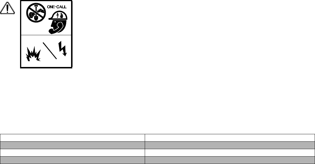
Before you start any digging project, don’t forget to call the local One-Call system in your area and any utility
company that does not subscribe to the One-Call system. For areas not represented by One-Call Systems
International, contact the appropriate utilities company or national regulating authority to locate and mark the
underground installations. If you don’t call, you may have an accident or suffer injuries; cause interruption of
services; damage the environment; or, experience job delays.
The One-Call representative will notify participating utility companies of your proposed digging activities. If
you are in the U.S. or Canada, and do not know the number for the local One-Call representative in your area,
dial the North American One-Call number, 1-888-258-0808, for this information. Utilities will then mark their
underground facilities by using the following international marking code:
WARNING: Always contact your local One-Call system before the start of your digging
project. The Interragator II GPS system is intended to be used with other utility locating
methods, such as the use of the One-Call system and potholing.
Electric shock or gas explosion can kill.
Red . . . . . . . . . . . . . . . . . . . . . . . . . . . . . . . . .Electric Yellow . . . . . . . . . . . . . . . . . . . . . . . . . . . . Gas, Oil, or Petroleum
Orange . . . . . . . . . . Communication, Telephone, TV Blue. . . . . . . . . . . . . . . . . . . . . . . . . . . . . . . . . . . . . Potable Water
Green/Brown . . . . . . . . . . . . . . . . . . . . . . . . . . Sewer White . . . . . . . . . . . . . . . . . . . . . . . . . . . . . Proposed Excavation
Pink . . . . . . . . . . . . . . . . . . . . . . . . . . . . . Surveying

10-4 Safety Messages Interragator II GPR System
WARNI NG : Failure to follow any of the preceding safety instructions, or those that follow within this
manual, could result in serious injury or death. This system is to be used only for those purposes for
which it was intended, as explained in this Operator’s Manual.