Geophysical Survey Systems MINIHR Ground penetrating radar User Manual Structure Scan III
Geophysical Survey Systems, Inc. Ground penetrating radar Structure Scan III
Users Manual

StructureScan
TM Mini HR
Quick Start Guide
A Fast Check List For Field
Operation
StructureScan Mini HR ....................................................................................................1
Section 1: Getting Started................................................................................................3
Section 2: Configuring the Structure Scan Mini HR .........................................................5
Section 3: Collecting Data..............................................................................................10
Section 4: Data Playback and Review ...........................................................................16
Section 5: Reset to Factory Settings..............................................................................22
Section 6: StructureScan Mini HR 3D - Collecting and Processing 3D Data .................23
Appendix A: Inventory of Your System ..........................................................................39
Appendix B: Battery/Charger Information ......................................................................40
Appendix C: Sample Data..............................................................................................41
Appendix D: Laser Information.......................................................................................45
Copyright © 2009-2011 Geophysical Survey Systems, Inc. MN70-635 Rev-
All Rights Reserved

Limited Warranty, Limitations Of Liability And Restrictions
Geophysical Survey Systems, Inc. hereinafter referred to as GSSI, warrants that for a period of 24 months from the delivery date to the
original purchaser this product will be free from defects in materials and workmanship. EXCEPT FOR THE FOREGOING LIMITED
WARRANTY, GSSI DISCLAIMS ALL WARRANTIES, EXPRESS OR IMPLIED, INCLUDING ANY WARRANTY OF
MERCHANTABILITY OR FITNESS FOR A PARTICULAR PURPOSE. GSSI's obligation is limited to repairing or replacing parts
or equipment which are returned to GSSI, transportation and insurance pre-paid, without alteration or further damage, and which in
GSSI's judgment, were defective or became defective during normal use.
GSSI ASSUMES NO LIABILITY FOR ANY DIRECT, INDIRECT, SPECIAL, INCIDENTAL OR CONSEQUENTIAL
DAMAGES OR INJURIES CAUSED BY PROPER OR IMPROPER OPERATION OF ITS EQUIPMENT, WHETHER OR NOT
DEFECTIVE.
Before returning any equipment to GSSI, a Return Material Authorization (RMA) number must be obtained. Please call the GSSI
Customer Service Manager who will assign an RMA number. Be sure to have the serial number of the unit available.
Regulatory Information
Please see the GSSI Manual CD or our website, www.geophysical.com/regulatoryinformation.htm, for current information and
FCC Registration Form, including:
• FCC Notice for U.S. Customer
• Canadian Requirements for RSS-220
• Declaration of CE Conformance
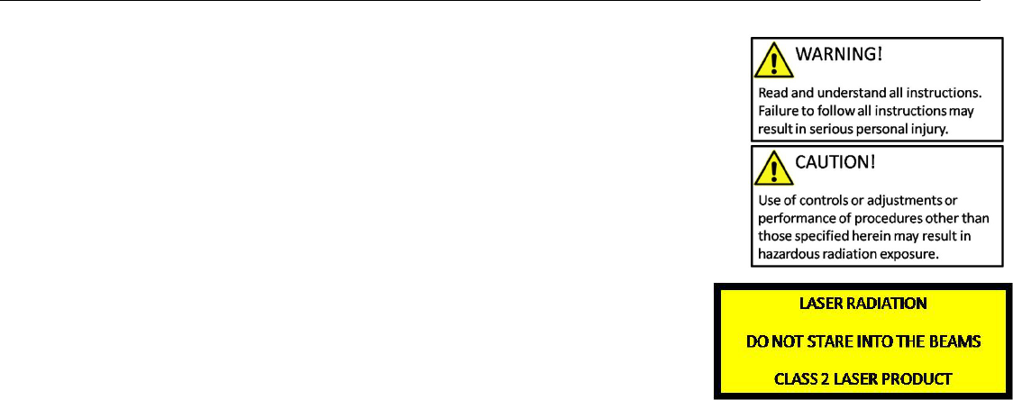
Laser Cautions and Warnings
Please see Appendix D for important laser cautions and warnings.
Garantie limitée, limites de responsabilité et restrictions
Geophysical Survey Systems, Inc, ci-après dénommé GSSI, garantit à l'acheteur original de ce produit que, pendant une
période de 24 mois à compter de la date de livraison, ce dernier sera exempt de défauts de matériaux et de fabrication.
EXCEPTE POUR CETTE GARANTIE LIMITÉE, GSSI REJETTE TOUTE GARANTIE, EXPLICITE OU IMPLICITE,
Y COMPRIS TOUTE GARANTIE DE QUALITE MARCHANDE OU D'ADEQUATION A UN USAGE
PARTICULIER. L’obligation de GSSI est limitée à la réparation ou le remplacement de pièces ou équipements qui sont
retournés à GSSI, transport et assurance prépayés, sans altération ni d'autres dommages, et qui, d’après GSSI, étaient
défectueux ou sont devenus défectueux lors d’une utilisation normale.
GSSI N'ASSUME AUCUNE RESPONSABILITE POUR LES DOMMAGES DIRECTS, INDIRECTS, SPÉCIAUX,
INCIDENTS OU CONSEQUENTS OU BLESSURES CAUSEES PAR UNE BONNE OU MAUVAISE UTILISATION
DE SON EQUIPEMENT DÉFECTUEUX OU NON.
Avant de retourner tout équipement à GSSI, une autorisation de retour matériel (RMA) doit être obtenue. Appelez s'il
vous plaît le service clientèle GSSI qui attribuera un numéro de RMA. Soyez sûr d'avoir le numéro de série de l'unité.
Informations réglementaires
L'utilisation des antennes GSSI est régie par différents organismes de réglementation à travers le monde. Certains modèles
d'antenne spécifiques doivent être certifiés pour un fonctionnement légal dans votre pays. Merci de lire et comprendre les
passages suivants de réglementation qui s'appliquent à votre antenne. Une liste des antennes certifiées par région peut être
trouvée sur www.geophysical.com / regulatoryinformation.htm.
Avis
La mise en œuvre est soumise aux deux conditions suivantes: (1) cet appareil ne doit pas provoquer d'interférences et (2)
cet appareil doit accepter toute interférence, y compris les interférences qui peuvent causer un fonctionnement non désiré
de l'appareil.
Quick Start Guide StructureScan Mini HR
Geophysical Survey Systems, Inc.
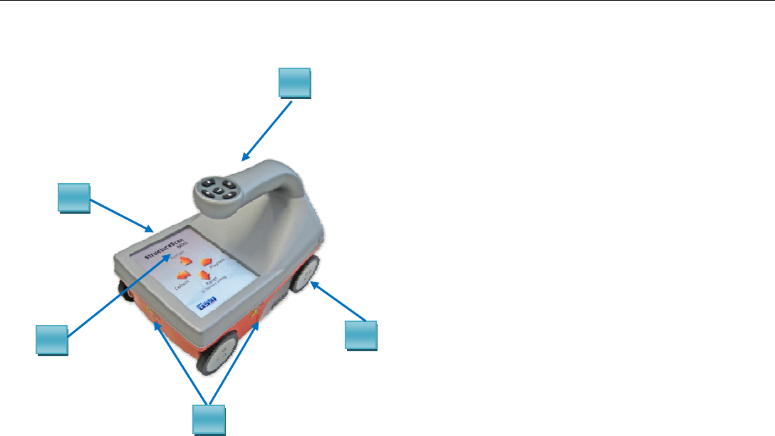
StructureScan Mini HR
Front/Top View 1
3
2
4
4
2 Easy to use operator interface with
color display screen
3 Survey wheel encoder
4 Guiding laser for locating
1 Ergonomic handle and controls

Quick Start Guide StructureScan Mini HR
Geophysical Survey Systems, Inc.
Back View
7
6
8
6 Wrist strap
7 Battery
8 SDR Card/Slot
9 USB-B Port
5 Power Button
9
5
Quick Start Guide StructureScan Mini HR
Geophysical Survey Systems, Inc.
Section 1: Getting Started
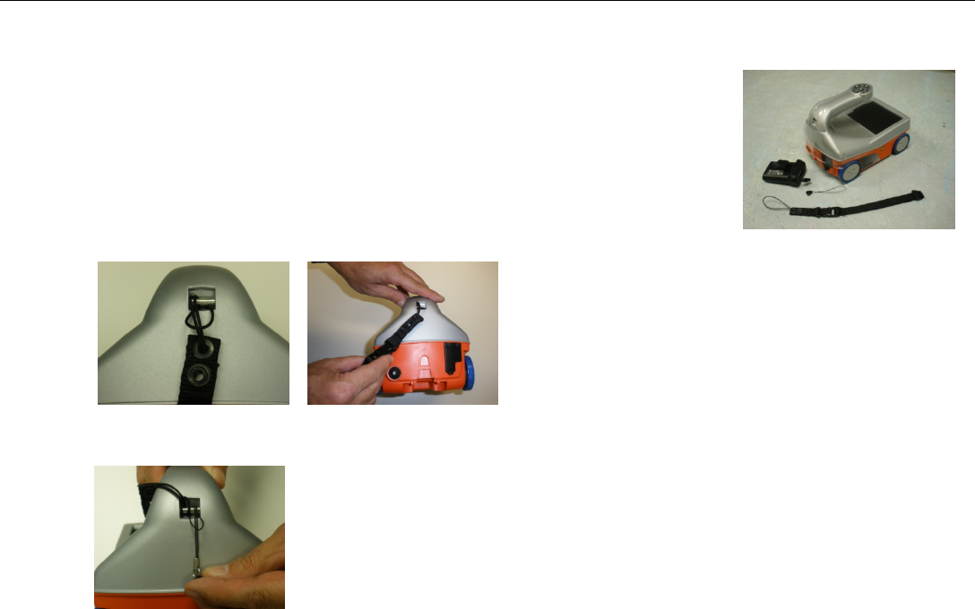
1 Preparing the StructureScan Mini HR.
• Remove the protective plastic cover.
• Remove the blue tape from the wheels.
• Attach the wrist strap to the back of the Mini HR. The wrist strap should go
around your wrist to prevent the Mini from being dropped.
• Attach the lanyard to the back of the MiniHR. The battery lanyard will attach to this lanyard to prevent the
battery from falling out.
Quick Start Guide StructureScan Mini HR
Geophysical Survey Systems, Inc. 2
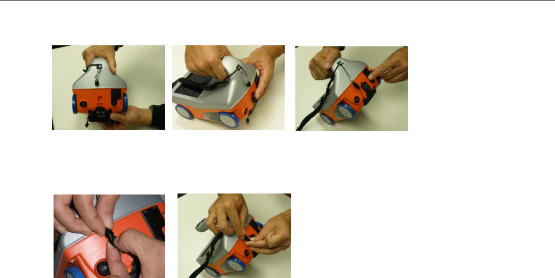
• Insert the battery into the battery slot in back of the Mini HR. Lift the tab upward and “snap” the tab into
place.
• Attach the battery lanyard to the lanyard on the Mini HR.
Quick Start Guide StructureScan Mini HR
Geophysical Survey Systems, Inc. 3
•
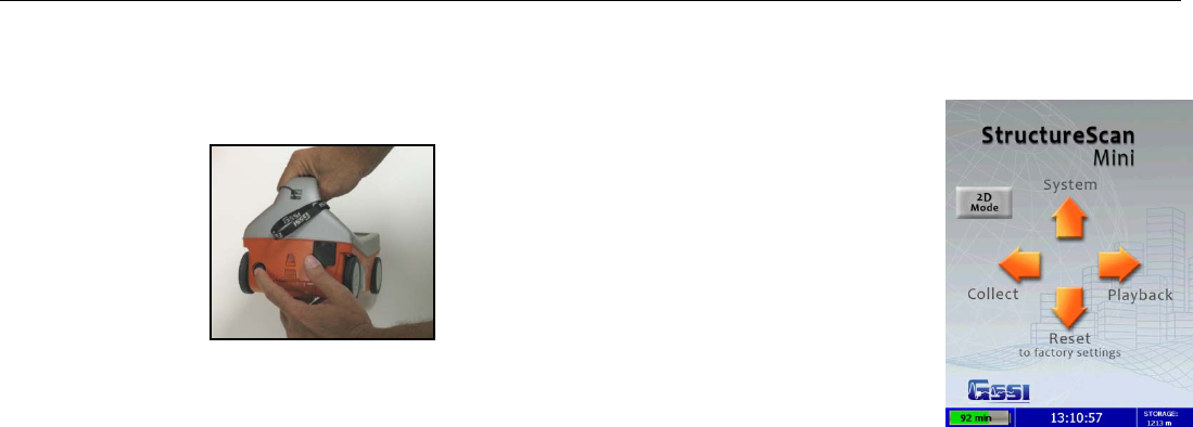
2 Powering up the StructureScan Mini HR.
• Press the power button. A green light will illuminate on the power button.
• After a few seconds, the system will boot up and the splash screen (Main Menu)
is displayed.
• The Green/Gray bar that is displayed on the lower left hand corner is a battery
life indicator. This will display how much battery time is remaining.
• The current time (as stored in the Mini HR) is displayed at the bottom of the screen.
• How much storage you have left (the distance you have left to scan) is displayed on the lower right hand
corner.
Quick Start Guide StructureScan Mini HR
Geophysical Survey Systems, Inc. 4
3 To power off the Mini HR, simply press and hold the power button for approximately 2 seconds. Then you may
remove the battery by pressing down on the tab of the battery and pulling down.
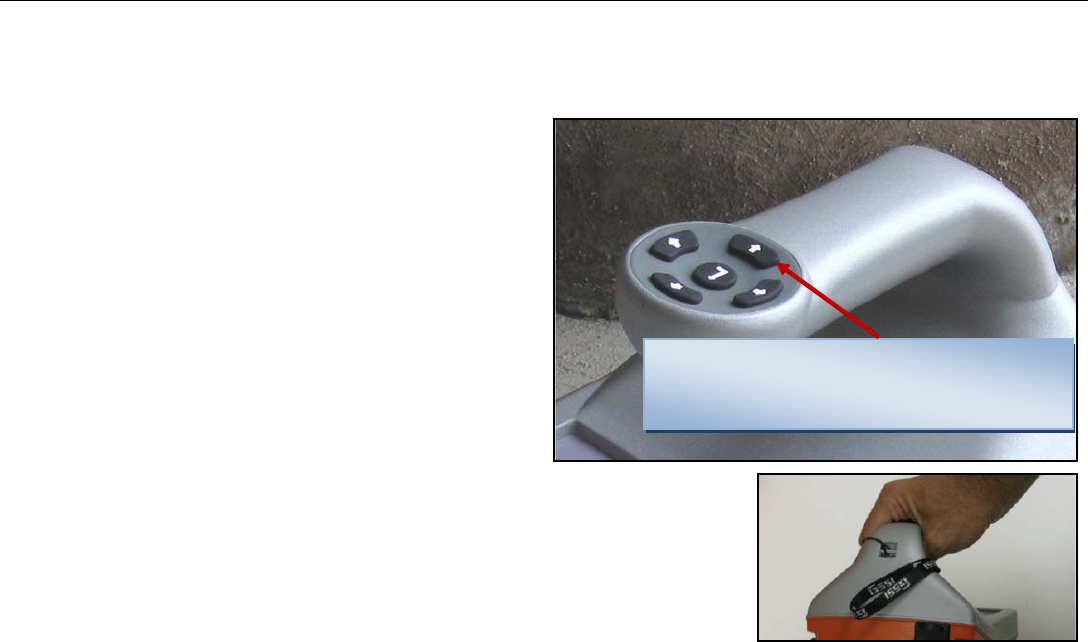
4 Note the buttons on the handle of the Mini HR.
They will be referred as Left ArrowÍ, Right Arrow
Î, Up Arrow Ï, Down Arrow Ð, and the Enter
buttons relative to the screen.
5 Depending upon the orientation of the screen on the
Mini HR (Left or Right depending upon which hand
you use), the Left, Right, Up, and Down buttons are
switched. However, you will still be pressing Í Î,
Ï, and Ð buttons, regardless of the orientation of
the screen. The Enter button ( ) is located in the
center of the keypad. button
• At any time and unless otherwise noted, you
may press the Arrow button closest to the rear
of the Mini HR to return to the previous screen or menu.
This will be known as the “Back” button.
Unless otherwise noted, this button,
regardless of orientation, will return you to
the previous screen or menu.
Quick Start Guide StructureScan Mini HR
Geophysical Survey Systems, Inc. 5
Section 2: Configuring the Structure Scan Mini HR
Before collecting any data, configure your Mini HR for 2D or
3D data collection by pressingSystem Menu Options
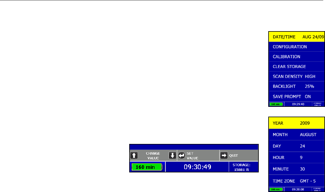
1 From the Main Menu, select System by pressing Ï.
2 Use Ï and Ð buttons to highlight the appropriate options under the System Menu.
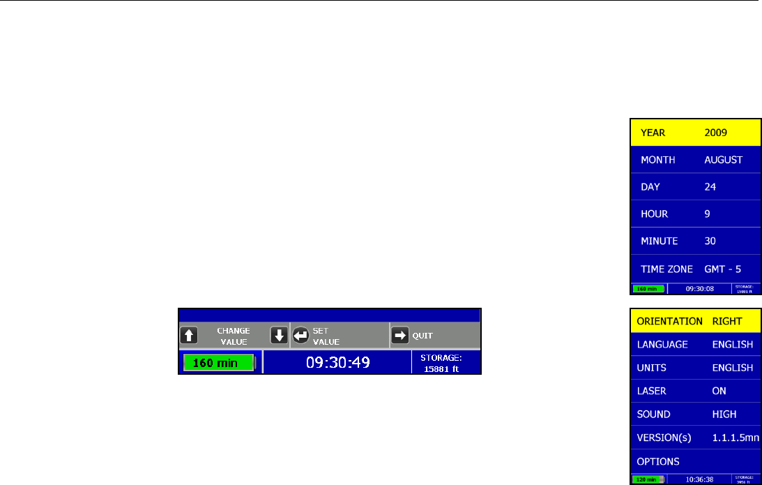
Date/Time: Configuring Date and Time
1 Highlight Date/Time and then press .
2 Highlight any of the options you wish to change and then press . The following options
will appear at the bottom of the screen:
• Change Value – Use Ï and Ð to change the value.
• Set Value – Press to accept
your change.
• Quit – Press Î to quit WITHOUT
saving the changes.
3 Press Î to return to the previous menu.
Quick Start Guide StructureScan Mini HR
Geophysical Survey Systems, Inc. 6
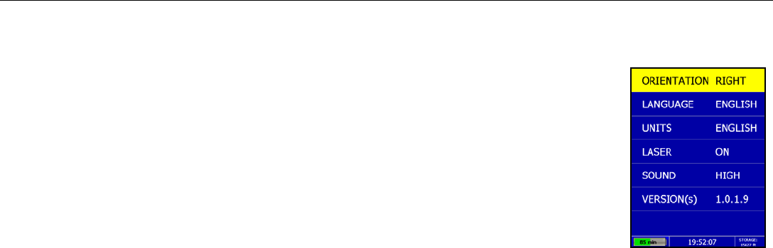
Configuration: Configuring Orientation, Language, Units, Laser, and Sound
1 Highlight Configuration and then press .
2 Press Ï Ð to select the appropriate options:
• Orientation – Press to toggle between Right or Left. This will flip the screen to
allow for either right or left handed operation.
• Language – Press to select your language preference.
• Units – Press to toggle between English or Metric.
• Laser – Press to toggle laser On or Off. If configured On, the laser will light up in
the Collect Menu only. Note: The laser will blink (whether configured On or Off)
when battery life is low (10%). Caution: Do not stare into beam.
• Sound – Press to toggle between High, Medium, Low, or Off.
• Version(s) – Press to display the version number of the software. Please visit GSSI’s web site for updates
to the firmware.
3 Press Î to return to the previous menu.
Quick Start Guide StructureScan Mini HR
Geophysical Survey Systems, Inc. 7
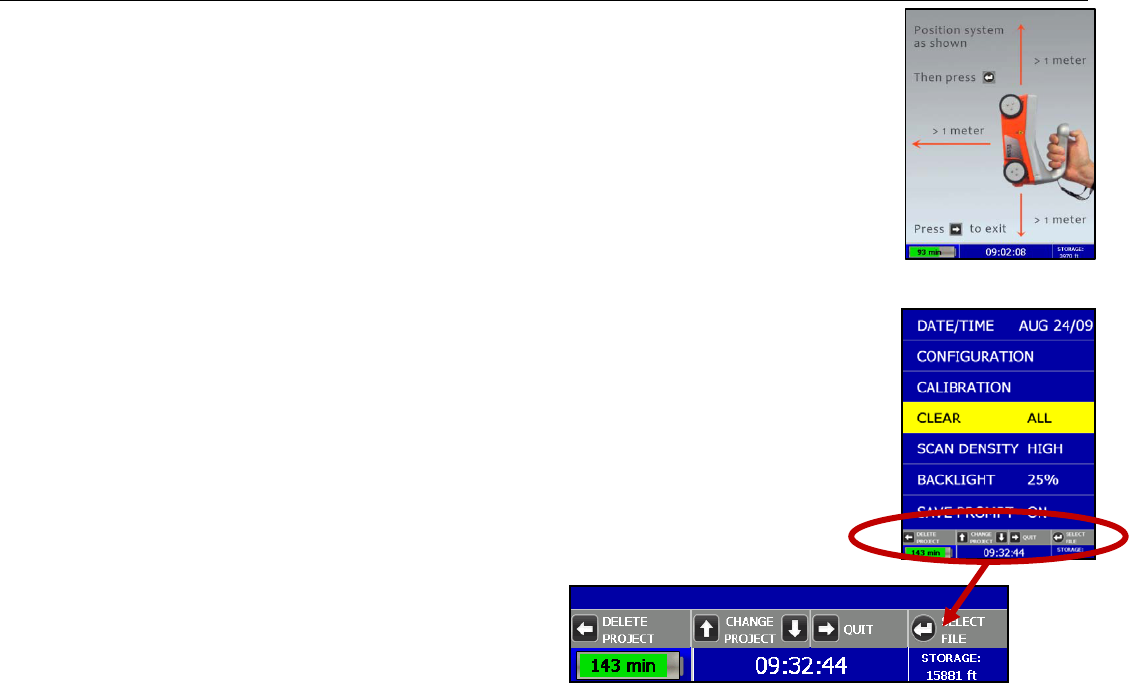
Calibration: Auto Calibrations for Surface and Brightness
1 Highlight Calibration and press
a) Hold the Mini HR upside down about 1 meter (3 ft) from any surface.
b) Press . The Auto-Calibration will take several seconds.
2 Press Î to return to the previous menu.
The Mini HR will then shut down after calibration and will require a re-startClearing
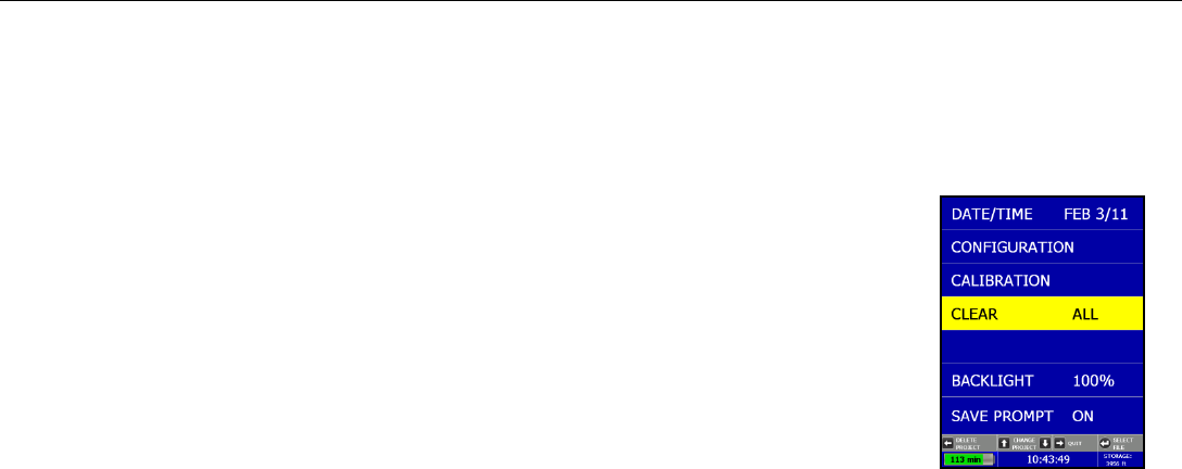
Storage: Deleting Saved Data
A project is a folder which holds individual files.
1 Highlight Clear Storage and press
2 At the bottom of the screen, a new set of options is displayed.
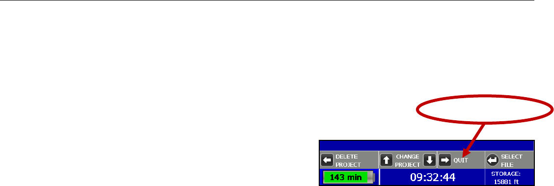
Deleting All Projects or Deleting Specific Projects
All Projects: If you wish to delete ALL of your projects and all the files associated with each
project:
1 Press Í when Clear All is displayed.
2 Press Ï to confirm, Ð to cancel the deletion.
Quick Start Guide StructureScan Mini HR
Geophysical Survey Systems, Inc. 8
Specific Projects: If you wish to delete a specific project or specific files within a project:
1 Press Ï Ð to select the specific project.
2 Press Í to delete that entire project (and all the files associated with that project).
3 Press Ï to confirm, Ð to cancel.
4 At any time, you may press Î to quit.
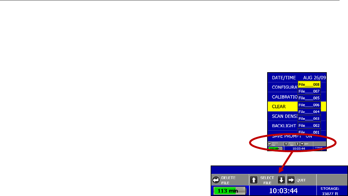
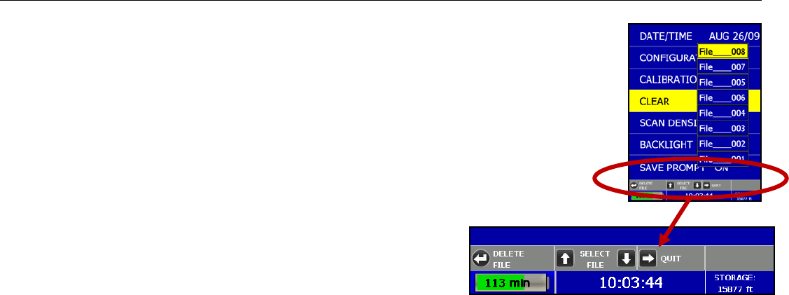
Specific Files in a Specific Projects: Deleting specific files within a specific project:
1 Press Ï Ð to select a specific project.
2 Press to select that project.
3 Press Ï Ð to select a specific file.
4 Press button to delete the selected file.
5 Press Ï to confirm, Ð to cancel.
6 At any time, you may press Î to quit.

Quick Start Guide StructureScan Mini HR
Geophysical Survey Systems, Inc. 9
Scan Density: Selecting the Scan Density
1 Highlight Scan Density.
2 Press to toggle between High and Normal.
• High – The Mini HR will scan at 8 scans/cm (approximately 240 scans/ft). Use this is when you are looking
for very small objects.
• Normal – The Mini HR will scan at 4 scans/cm (approximately 120 scans/ft). Use this is when you are
looking for normal size objects.
Note: Disabled in 3D data collection mode
Backlight: Setting the Brightness of the Mini HR Backlight
1 Highlight Backlight.
2 Press to toggle between 25%, 50%, 75%, or 100%.
Save Prompt: Whenever Saving, Have the System Prompt You to Save or Save Automatically
1 Highlight the Save Prompt.
2 Press to toggle between On or Off.
• On – The system will prompt you to save a file after you choose to save a file.
• Off – The system will save the file automatically after you choose to save a file.
Quick Start Guide StructureScan Mini HR
Geophysical Survey Systems, Inc. 10
Section 3: Collecting Data
After the configuration is complete, you are now ready to collect data.
Important Note: To assure consistency of StuctureScan Mini HR’s naming of the files collected
and saved, it is highly recommended that the SD card be inserted prior to any data collection.
Collect Menu Options
1 From the Main Menu, select Collect by pressing Í.
2 Use Ï Ð buttons to highlight the appropriate options under the Collect Menu.
Before you begin to collect data you may want to configure the Mini HR for a particular
scan/project.
Project: Saving Files to a Specific Project
1 Highlight Project and press
2 Highlight a Project number and press . All files that you save during collection will be saved under this
project. (Note: you may want to take field notes to document what files were saved in which project).
Depth: Selecting the Depth Where You are Scanning
1 Highlight Depth.
2 Press to toggle between 8, 12, and 16 inches (20, 30, and 40 cm).
Quick Start Guide StructureScan Mini HR
Geophysical Survey Systems, Inc. 11
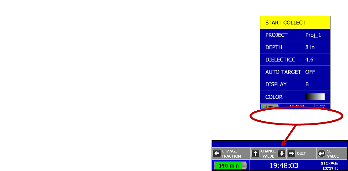
Dielectric: Selecting the Approximate Dielectric of the Area You are
Scanning
1 Highlight Dielectric and press . Change the Dielectric value by:
• Press Í to change the number after the decimal point.
• Press Ï Ð to change the number before the decimal point.
• Press Î to quit WITHOUT saving the new value.
• Press to set your new value.
Having the correct value will improve your depth accuracy. A higher value is necessary for
young concrete or concrete that is under water.
• Less than 2 months/outside in wet environment, use 9+
• Younger than 12 months/outside, use 7-8
• Older than 12 months/indoor/dry, use 5-6
For more detailed information on concrete dielectric values, refer to the
GSSI Handbook for RADAR Inspection of Concrete that came with your
system on the documentation CD.
Quick Start Guide StructureScan Mini HR
Geophysical Survey Systems, Inc. 12
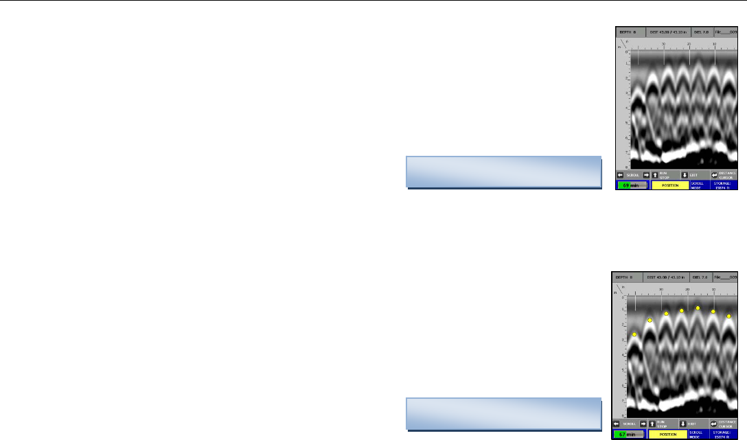
Auto target: Allowing the Mini HR to Automatically Pick Your Targets
1 Highlight Auto Target.
2 Press to toggle between On and Off.
• On – The Mini HR will place dots on what it interprets as targets as you collect data, and when pulling
the Mini straight back.
• Off – No dots and no interpretation will be done by the Mini HR
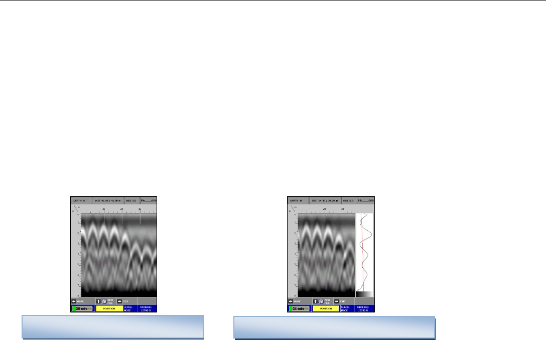
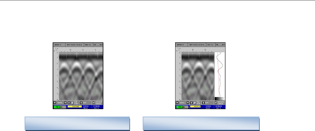
Display: While Collecting Data, Display Data Only or Data + O-Scope
1 Highlight Display.
2 Press to toggle between B (data only) and A+B (data + o-scope).
Data only display during collection Data + O-Scope display during collection
Quick Start Guide StructureScan Mini HR
Geophysical Survey Systems, Inc. 13
Color: Choosing the Colors You Want Displayed During Data Collection
1 Highlight Color.
2 Press to toggle between five the different color schemes available for data display
during collection.
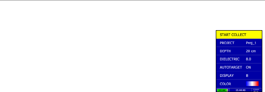
Collecting Data and Marking Your Targets
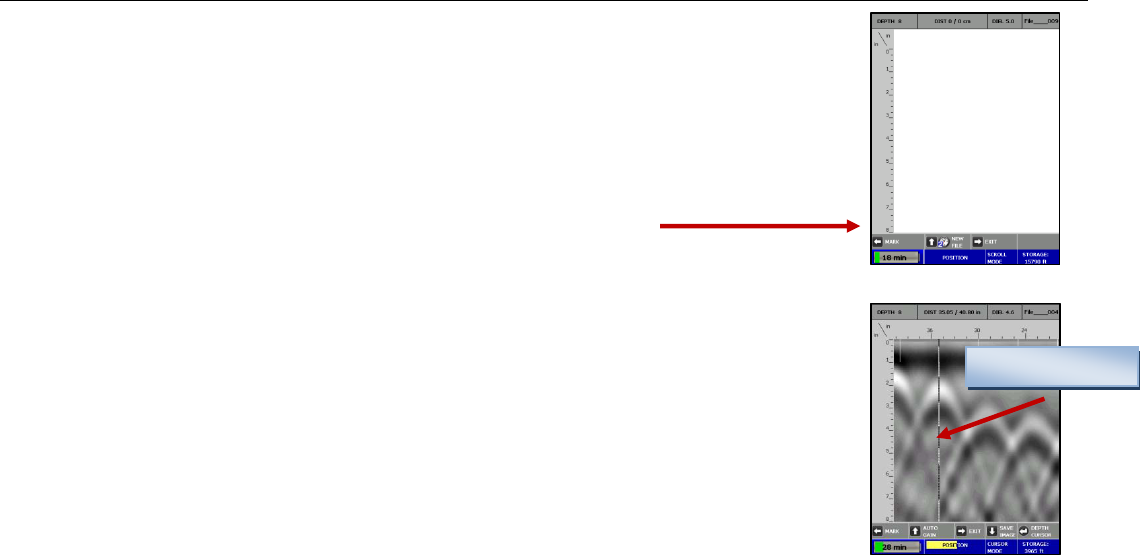
1 Highlight Start Collect and press . This screen is displayed.
2 Note the information at the top of the screen:
• Depth – The depth you have chosen for this scan.
• Dist. – The distance you have scanned.
• Diel. – The dielectric you have chosen for this scan.
• “File____XXX” – The filename of this scan if you choose to save this file.
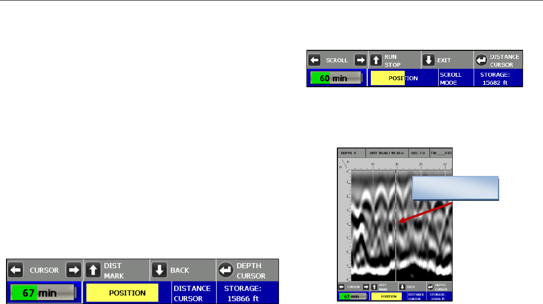
3 Move your cart forward. Data only gets collected when you move the cart forward.
4 Once you start seeing hyperbolas on the screen, pull the system straight back along your
survey line. You will see a vertical line (the backup cursor) scroll along your data.
When that vertical line is right over the apex of the hyperbola, the center of the antenna
is over that target.
Note: When you pull the Mini HR straight back, and if you configured Auto Target On, the Mini will interpret
target locations by placing yellow dots on the targets.
Backup Cursor
Quick Start Guide StructureScan Mini HR
Geophysical Survey Systems, Inc. 14
5 The center of the antenna is directly under the Mini HR. After marking the location of the target on the ground
using the laser (if configured On) at each side of your cart as a guide (or the groove on each side of the cart as a
guide if the laser is configured Off). Push the cart straight forward or move the cart to do another line scan. No
data will be collected until you have passed the spot where you started to reverse.
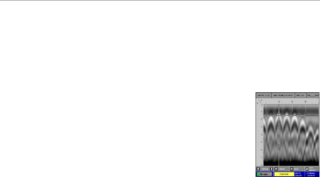
6 If you wish, you may calibrate depth (optional). Match the target location in the data to its location in your survey
area. Drill down to that target and measure the depth.
a) Backup the Mini HR and press “Depth Cursor” to display crosshairs and set them over the target in the
data.
b) Press Ï Ð to line up the horizontal line in the middle of first dominant color of that
target.
c) Press to Set Depth.
d) Press Ï Ð until the Depth in the upper left hand corner matches the measured
depth.
e) Press Í to Set Depth. The vertical scale will adjust and the dielectric will be
updated. Please note that this is only an approximation of the true depth because the
dielectric value or constant can change with depth and across the site.
f) Press Î to continue scanning.
Quick Start Guide StructureScan Mini HR
Geophysical Survey Systems, Inc. 15
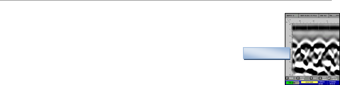
7 Auto Gain Feature
At times, while collecting data, the screen may be over or under gained. To correct this, backup
the Mini HR and press Ï Auto Gain. This will correct the gain without changing the dielectric.
Continue forward to collect data with the new gain setting.
8 Save Image `
To save an image of the data that was collected, backup the Mini HR and press Ð Save Image.
The file will save as a Bitmap file.
Over Gained
9 Other Options
• While collecting data (with no backup cursor on the screen), press and HOLD Ï (New File) to save your
current file. If you have configured Save Prompt On, you will be prompted to confirm the save. Press Ï to
save, Ð to not save the data. If you have configured Save Prompt Off, it will save automatically.
• Press Í to place a user mark in your data.
• Press Î to exit. If you have configured Save Prompt On, you will be prompted to confirm the save. Press Ï
to save, Ð to not save the data. If you have configured Save Prompt Off, it will save automatically.
Helpful Hint: Make a sketch map of your survey area with immovable objects as reference points. Sketch in your survey
files, note the start and stop points, direction of travel, and file name on the map. This will make it much easier to relocate
your targets after the survey.
Helpful Hint: The top of a target is generally the middle of the first positive peak for metal targets (rebar, tensioned cable,
wires in PVC, conduit). If you are working in a grayscale color table, the positives are white. If the utility is air or gas
filled (empty PVC, voids) the top of the target is the middle of the first negative peak (black). Please refer to Appendix C
for examples of the different types of data.
Quick Start Guide StructureScan Mini HR
Geophysical Survey Systems, Inc. 16
Section 4: Data Playback and Review
The Playback menu provides tools to help you interpret your data. None of these functions are required to get
interpretable data. They are simply meant to help you in the interpretation of the data. These functions do not permanently
change your data or affect your saved data in any way. More intensive processing can be done in the RADAN processing
program (sold separately).
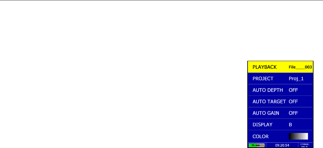
Playback Menu Options
1 From the Main Menu, select Playback by pressing Î.
2 Use Ï Ð to highlight the appropriate options under the Playback Menu.
Before you begin to playback data (Playback), you may want to configure the Mini HR to
give you some helpful tools in the interpretation of the data.
Project: Selecting a Specific Project to Select a Specific File to Playback
1 Highlight Project.
2 Highlight and press to select the project where the file you want to play back is
located.
3 Use Ï Ð to scroll down or up.
4 Highlight and press to select the specific file you want to play back.

Quick Start Guide StructureScan Mini HR
Geophysical Survey Systems, Inc. 17
Auto Depth: Automatically Adjusting Depth Scale
1 Highlight Auto Depth.
2 Press to toggle between Auto and Orig.
• Auto – The Mini HR will estimate the depth of targets and automatically adjust the Depth Scale.
• Orig – The Mini HR will use the original value set during collection.
Auto Target: Allowing the Mini HR to Automatically Pick Your Targets
1 Highlight Auto Target.
2 Press to toggle between On and Off.
• On – The Mini HR will place dots on what it interprets as targets.
• Off – No dots and no interpretation will be done by the Mini HR.
Note: Auto Target is for information purposes only and you should carefully examine your data to ensure that the
Mini HR has correctly located objects.
Auto Gain: Allowing the Mini HR to Automatically Configure the Gain
1 Highlight Auto Gain.
2 Press to toggle between On and Off.
• On – The Mini HR will reconfigure the gain.
• Off – The Mini HR will use the gain used during data collection.
Quick Start Guide StructureScan Mini HR
Geophysical Survey Systems, Inc. 18
Display: While Viewing Data, Display Data Only or Data + O-Scope
1 Highlight Display.
2 Press to toggle between B (data only) and A+B (data + O-scope).
Data only display during collection Data + O-Scope display during collection
Color: Choosing the Colors to Display during Data Collection
1 Highlight Color.
2 Press to toggle between five different color schemes to be displayed during collection.
Quick Start Guide StructureScan Mini HR
Geophysical Survey Systems, Inc. 19
Playing Back the Selected File
1 Highlight Playback.
2 Press to play back the selected file.
Note at the top of the screen the following information:
• Depth
Data with Auto Target OFF
• Distance
• Dielectric
• File name
While in Playback, you will have an option to toggle between four different modes by simply pressing the Enter button.
The mode you are in will be displayed at the bottom of the screen.
Scroll Mode – Allows you to scroll your data left and right
Distance Cursor Mode – Allows you to move a vertical line left and right on your data
Depth Cursor Mode – Allows you to move a horizontal line up and down on your data.
Set Depth Mode – Allows you to set a known depth to your targets.
Data with Auto Target ON
Quick Start Guide StructureScan Mini HR
Geophysical Survey Systems, Inc. 20
Scroll Mode
Í Î – Scroll through your data.
Ï – Run Stop, while your data is scrolling, press Up Arrow to stop
and start the scrolling. Hold this button for 2 seconds will load the
next file in the project.
Ð – Exit back to the Playback menu. If you added or deleted any targets, the system will prompt you to save your targets.
Press Ï for Yes, Ð for No.
– Switch to Distance Cursor Mode.
Vertical Line
Distance Cursor Mode
Í Î – Move the vertical line left and right.
Ï – Place a user mark at the location of the vertical line.
Ð – Return to Scroll Mode.
- Switch to Depth Cursor Mode.
Quick Start Guide StructureScan Mini HR
Geophysical Survey Systems, Inc. 21
Depth Cursor Mode
Ï Ð – Move the horizontal line up and down.
Í – Toggles between placing and deleting a dot to mark a target where the cross hairs are.
Î – Return to Distance Cursor Mode.
- Switch to Set Depth Mode.
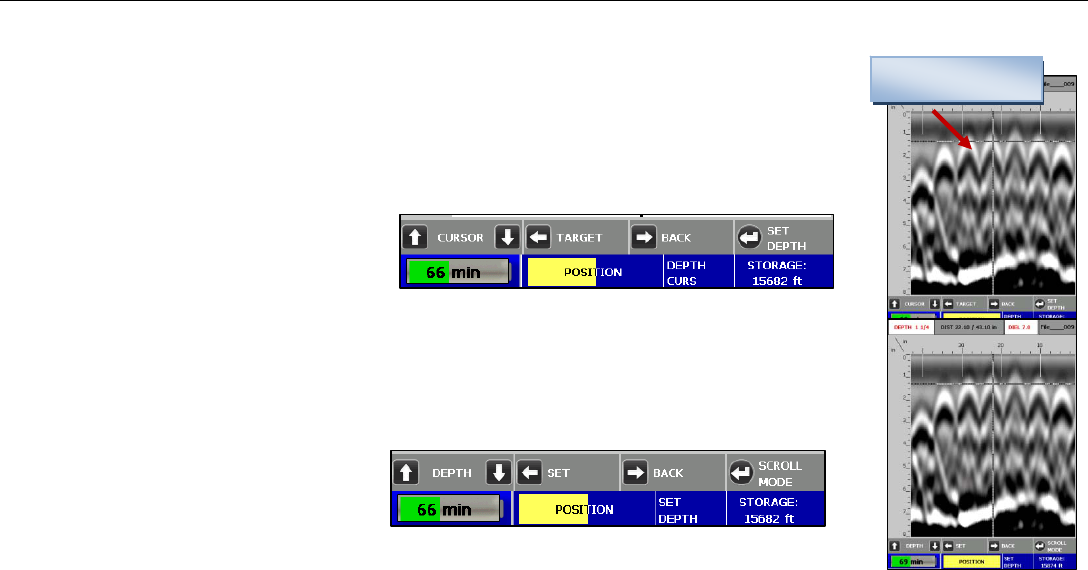
Set Depth Mode
Ï Ð – Entering a known depth for the target in the crosshairs. The upper left hand corner displays
the depth
Horizontal Line
Í – Once the correct depth is displayed, set the depth. Note: If the depth of a target changes, this
will automatically change the dielectric.
Î – Return to Depth Cursor Mode.
– Switch to Scroll Mode.

Quick Start Guide StructureScan Mini HR
Geophysical Survey Systems, Inc. 22
Section 5: Reset to Factory Settings
This will reset the Mini HR to the factory settings. This will NOT delete the data you have saved.
Simply press the Down Arrow from the Main Menu.
Ï to Confirm.
Ð to Cancel.
Quick Start Guide StructureScan Mini HR
Geophysical Survey Systems, Inc. 23
Section 6: StructureScan Mini HR 3D - Collecting and Processing
3D Data
The StructureScan Mini HR comes with 3D collecting and
processing if you have purchased this feature. You may also upgrade
to this feature with your current StructureScan Mini HR if you did
not originally purchase this feature. Contact your GSSI sales
representative for upgrade information.
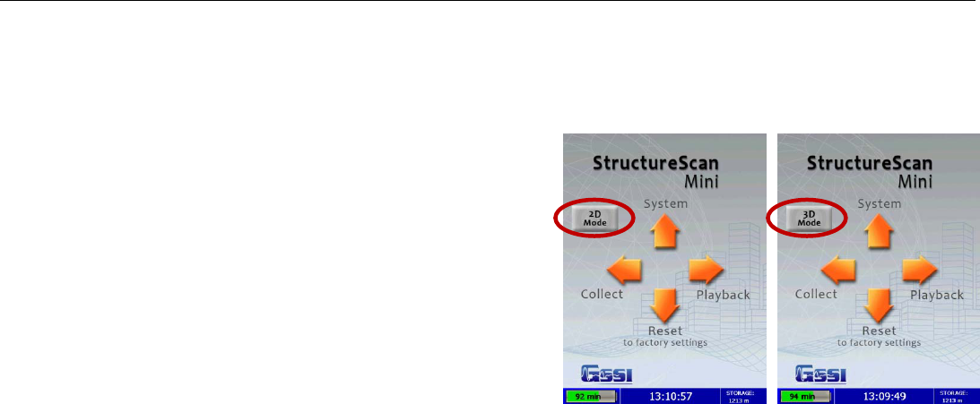
If you have the 3D feature, there will be a new option on the screen
upon booting your StructureScan Mini HR. There will be a button
that allows you to toggle between 2D and 3D mode. Simply press the
Enter Key to toggle between 2D and 3D mode.
Quick Start Guide StructureScan Mini HR
Geophysical Survey Systems, Inc.
Configuring the StructureScan Mini HR for 3D Collection
1 From the Main Menu, select System by pressing Ï.
2 Use Ï and Ð buttons to highlight the appropriate options under the System Menu.
Date/Time: Configuring Date and Time
1 Highlight Date/Time and press .
2 Highlight any of the options you wish to change and press The following options will
appear at the bottom of the screen:
• Change Value – Use Ï and Ð to change the value.
• Set Value – Press the Enter button to accept your change.
• Quit – Use Î to quit WITHOUT saving the changes.
24
3 Press Î to return to the previous menu.
Configuration: Configuring Orientation, Language, Units, Laser, and Sound
1 Highlight Configuration and press .
Quick Start Guide StructureScan Mini HR
Geophysical Survey Systems, Inc. 25
2 Press Ï Ð to select the appropriate options:
• Orientation – Press to toggle between Right or Left. This will flip the screen
to allow for either right or left handed operation..
• Language – Press to select your language preference.
• Units – Press to toggle between English or Metric.
• Laser – Press to toggle laser On or Off. If configured On, the laser will light up in
the Collect Menu only. Note: The laser will blink (whether configured On or Off)
when battery life is low (10%).
Caution: Do not stare into beam.
• Sound – Press to toggle between High, Medium, Low, or Off.
• Version(s) – Press to display the version number of the software. Please visit
GSSI’s web site for updates to the firmware.
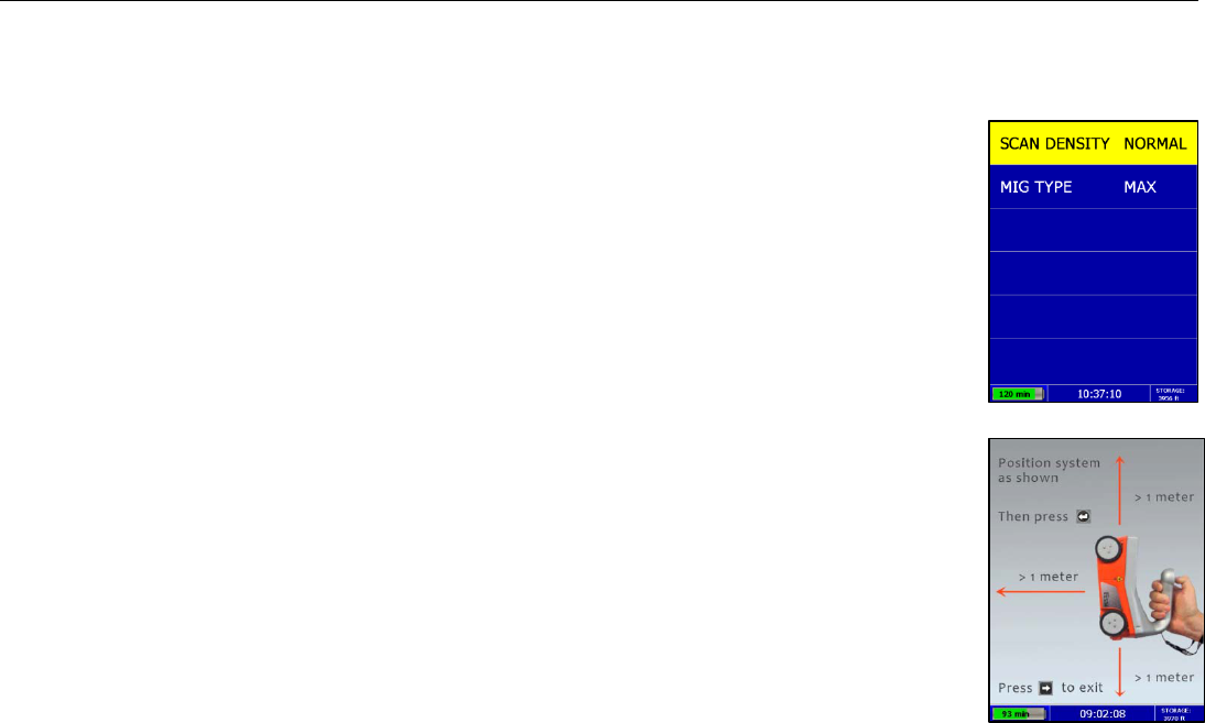
• Options – Press to configure Scan Density and Migration Type.
• Scan Density – Press to toggle between Normal and Low.
• Normal – The Mini HR will scan at 8 scans/cm (approximately 240 scans/ft).
• Low – The Mini HR will scan at 4 scans/cm (approximately 120 scans/ft).
• Mig Type – When Migrating the data, whether to use the full samples or half
samples.
• Max – Full number of samples (slower processing, but clearer picture).
• Half – Every other sample (faster processing, but not as clear picture).
• Press Î to return to the previous menu.
Quick Start Guide StructureScan Mini HR
Geophysical Survey Systems, Inc. 26
3 Press Î to return to the previous menu.
Calibration: Auto Calibrations for Surface and Brightness
1 Highlight Calibration and press .
a) Hold the Mini HR upside down about 1 meter (3 ft) from any surface.
b) Press . The Auto-Calibration will take several seconds.
2 Press Î to return to the previous menu.
Clear Storage: Deleting Saved Data
A project is a folder which holds individual files.
1 Highlight Clear Storage and press .
2 At the bottom of the screen, a new set of options is displayed.
Quick Start Guide StructureScan Mini HR
Geophysical Survey Systems, Inc. 27
Deleting All Projects or Deleting Specific Projects
All Projects: If you wish to delete ALL of your projects and all the files associated with each project:
1 Press Í when Clear All is displayed.
2 Press Ï to confirm, Ð to cancel the deletion.
Specific Projects: If you wish to delete a specific project or specific files within a project:
1 Press Ï Ð to select the specific project.
2 Press Í to delete that entire project (and all the files associated with that project).
3 Press Ï to confirm, Ð to cancel.
4 At any time, you may press Î to quit.
Quick Start Guide StructureScan Mini HR
Geophysical Survey Systems, Inc. 28
Specific Files in a Specific Projects: Deleting specific files within a specific project:
1 Press Ï Ð to select a specific project.
2 Press to select that project.
3 Press Ï Ð to select a specific file.
4 Press Î to delete the selected file.
5 Press Ï to confirm, Ð to cancel.
6 At any time, you may press Î to quit.
Backlight: Setting the Brightness of the Mini HR Backlight
1 Highlight Backlight.
2 Press to toggle between 25%, 50%, 75%, or 100%.
Save Prompt: Whenever Saving, Have the System Prompt
You to Save or Save Automatically
1 Highlight Save Prompt.
2 Press to toggle between On or Off.
• On – The system will prompt you to save a file after you choose to save a file.
• Off – The system will save the file automatically after you choose to save a file.
Quick Start Guide StructureScan Mini HR
Geophysical Survey Systems, Inc. 29
Collecting 3D Data
After your configuration is complete, you are now ready to 3D collect data.
Important Note: To assure consistency of StuctureScan Mini HR’s naming of the files collected
and saved, it is highly recommended that the SD card is inserted prior to any data collection.
Collect Menu Options
1 From the Main Menu, select Collect by pressing Í.
2 Use Ï Ð buttons to highlight the appropriate options under the Collect Menu.
Before you begin to collect data (Collect), you may want to configure the Mini HR for a particular
project.
3D Project: Saving Files to a Specific Project
1 Highlight Project and press
2 Highlight a Project number and press All files that you save during collection will be saved under this project.
(Note: you may want to take field notes to document what files went under which project).
Depth: Selecting the Depth Where You are Scanning
1 Highlight Depth.
2 Press to toggle between 8, 12, and 16 inches (20, 30, and 40 cm).
Quick Start Guide StructureScan Mini HR
Geophysical Survey Systems, Inc. 30
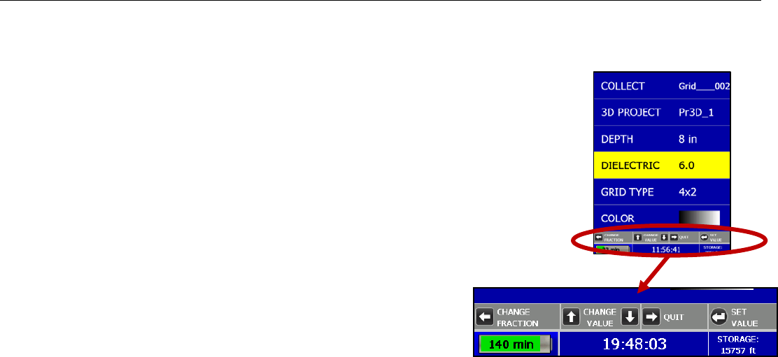
Dielectric: Selecting the Approximate Dielectric of the Area You are Scanning
1 Highlight Dielectric and press Change the Dielectric value by:
• Í to change the number after the decimal point.
• Ï Ð to change the number before the decimal point.
• Î to quit WITHOUT saving the new value.
• Press to set your new value.
Having the correct value will improve your depth accuracy. A higher value is necessary for
young concrete or concrete that is under water.
• Less than 2 months/outside in wet environment, use 9+
• Younger than 12 months/outside, use 7-8
• Older than 12 months/indoor/dry, use 5-6
For more detailed information on concrete dielectric values, refer to the
GSSI Handbook for RADAR Inspection of Concrete that came with your
system on the documentation CD.

Quick Start Guide StructureScan Mini HR
Geophysical Survey Systems, Inc. 31
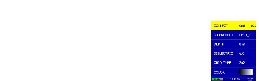
Grid Type: Toggle to Select Grid Size
1 Highlight Grid Type.
2 Press to toggle between 1 x 1, 2 x 2, or 4 x 2 (30 x 30, 100 x 100, 60 x 60, 120 x 60 cm)
Color: Choosing the Colors You Want Displayed During Data Collection
1 Highlight Color.
2 Press to toggle between five different color schemes to be displayed during collection.
Quick Start Guide StructureScan Mini HR
Geophysical Survey Systems, Inc. 32
Collect: Collect 3D Grid
Highlight Collect and press enter to begin collecting 3D data
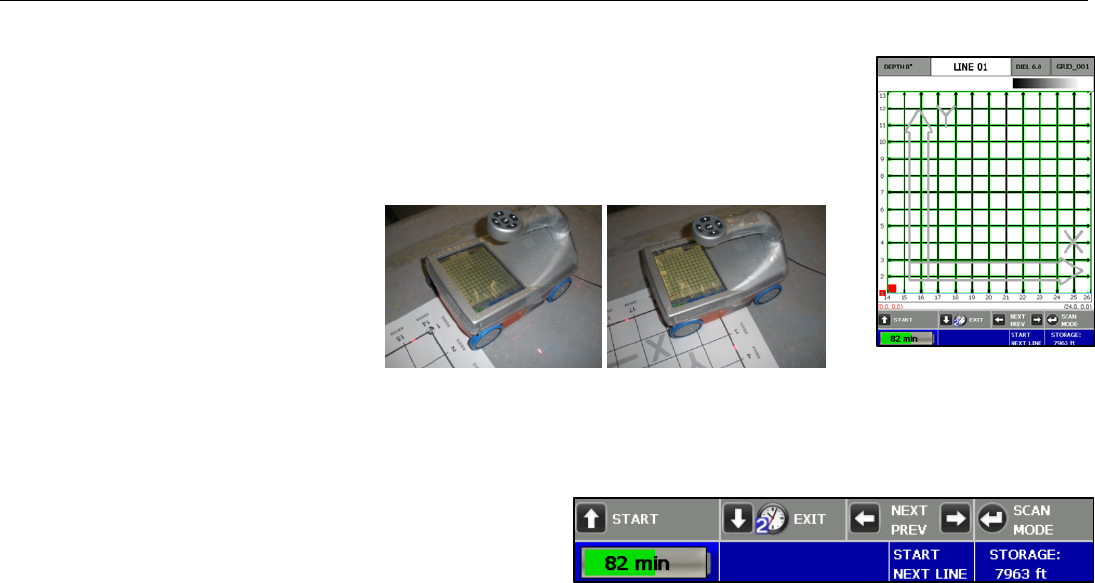
1 Begin by lining up the Mini HR with the appropriate pad. Using the lasers, line up the
laser pointing forward with Line 1. Line up the side lasers with the start line of the pad.
2 Once you have lined up the
Mini HR, Press the Start Button
Ï and then roll the Mini HR to
the other end of the grid. The
Mini HR will automatically stop
collecting once it reaches the end
of the grid.
3 Return the Mini HR to the start of the grid and line up the lasers with the next line and repeat the process until all
the lines needed are collected.
4 Note at the top of the screen. This displays which line number you should be collecting.
5 You may press the “Next\Prev” buttons, (Left\Right)
ÍÎ, to scan a specific line. This can be used if you
do not collect a line correctly and need to redo
a line.
6 Press Scan Mode, to toggle the view of the scan.
Quick Start Guide StructureScan Mini HR
Geophysical Survey Systems, Inc. 33
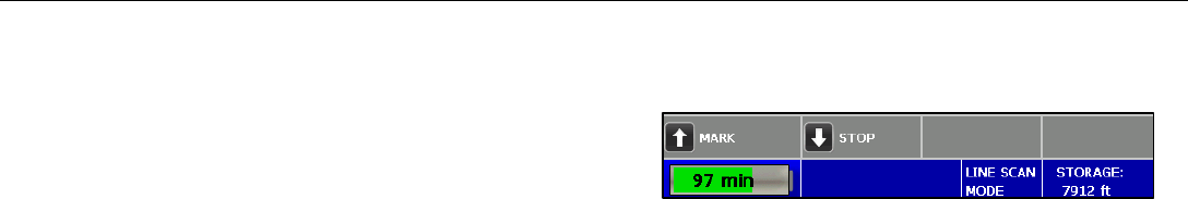
7 During collection, you may:
• Press the Mark Button Ï to place a mark in the data
as a reference point.
• Press the Stop Button Ð and hold for two seconds to
stop collecting that particular line because of an
obstacle.
8 When you are done collecting all the lines, press and hold the Exit Button Ð for two seconds. The Mini HR will
save, process, and display the grid (See Playback section for processing saved data).
Quick Start Guide StructureScan Mini HR
Geophysical Survey Systems, Inc. 34
Playback: Processing and Drawing the 3D Grid
There are two ways to process and draw the 3D Grid.
1 After you finished collecting the data by pressing and holding the Exit Button Ï for two seconds, The Mini HR
will save, process, and display the grid.
OR
2 From the Main Menu,press Î to select Playback
a) Highlight 3D Project and press to select the appropriate project and then select
the appropriate Grid.
b) Highlight Playback and press to process and draw the grid.
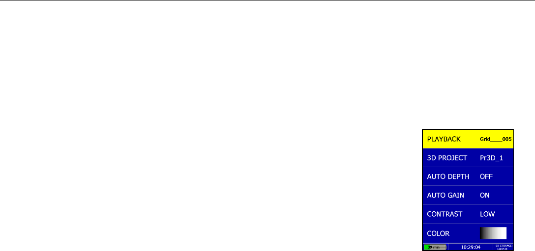
Other Playback Menu Options
Auto Depth – Press to toggle between On and Off.
• On – The Mini HR will estimate the depth of targets and automatically adjust the
Depth Scale.
• Off – The Mini HR will use the original value set during collection.
Auto Gain - Press to toggle between On and Off.
• On – The Mini HR will reconfigure the gain.
Quick Start Guide StructureScan Mini HR
Geophysical Survey Systems, Inc. 35
• Off – The Mini HR will use the gain used during data collection.
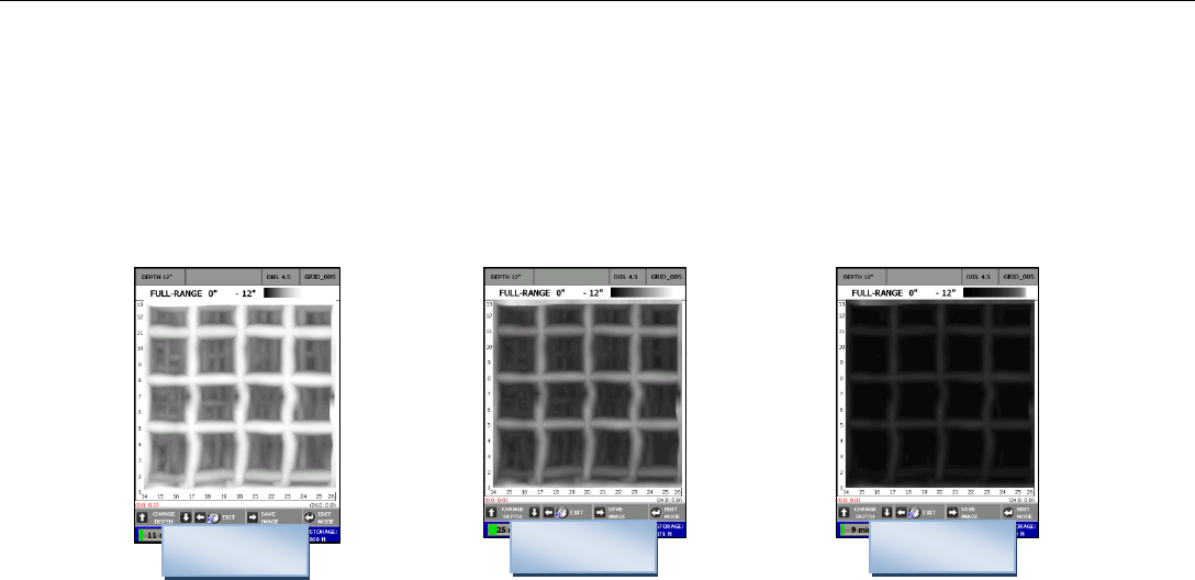
Contrast - Press to toggle between Lowest, Low, Medium, High, Highest.
• The lower the contrast, the more “positive” colors are displayed.
• The higher the contrast, the more “negative” colors are displayed.
• See the color scale below to see how much color is displayed as you toggle through these options. Low or
Medium are good defaults.
Color – Press to toggle between colors for display of the data.
Lowest Medium Highest
Once the Mini HR has processed the data, it will display the grid. You will be in Depth Slice Mode as noted at the bottom
of the screen.
Quick Start Guide StructureScan Mini HR
Geophysical Survey Systems, Inc. 36
Modes
You may press the Enter button to toggle between different modes for display and edit purposes.
They are: Depth Slice Mode, Cursor Mode, Color Mode, and Select Profile Mode.
Depth Slice Mode
1 The initial display will be the Full Range of the grid. Pressing the Ï from the Full Range will
decrease the range depth by ½ inch (1.27 cm) increments. Pressing the Ð will slice down
through the image in ½ inch (1.27 cm) increments. Note the top of the screen. It will display
the depth of the slice or the total depth of the slice.
2 Press Í and hold for two seconds to Exit.
3 Press Î to save the image as a .bmp file.
4 Press to toggle to Cursor Mode.
Cursor Mode
This will display crosshairs on the data so that X and Y coordinates located at the top of the screen
may be noted as the location of a target.
1 Press Ï Ð buttons to move the crosshair in the Y Direction.
2 Press Î to change the menu to the X Direction Mode so that you may move the crosshair in
the X Directions by pressing Ï Ð.
3 Note the X and Y coordinates at the top of the screen as you move the cross hairs.
4 Press Í to set a mark at the location of the crosshairs.
Quick Start Guide StructureScan Mini HR
Geophysical Survey Systems, Inc. 37
• Press Ð to place a dot at the location of the crosshairs.
• Press Í to place a line following the vertical line of the crosshairs.
• Press to return back to Edit Mode View.
5 Press to toggle to Color Mode.
Color Mode: Allow to change data color and contrast
1 Press Í to toggle between different colors.
2 Press Ï Ð to change the contrast of the screen.
3 Press to toggle to Select Profile Mode.
Select Profile Mode: Displays a specific 2D profile on the screen
1 Press Í Î to select which profile to display.
2 Press Ð to display the 2D profile.
• Press ÍÎ to display previous or next 2D Profile
• Press Ï to turn Focus on or off
• Press Ð to return to Select Profile Mode
• Press to change Dielectric.
• Press Ï Ð to change the Dielectric Value
• Press Í to return to the previous screen
Quick Start Guide StructureScan Mini HR
Geophysical Survey Systems, Inc. 38
• Press Î to change the gain
• Press to set the new Dielectric.
3 Press to return to Depth Slice Mode
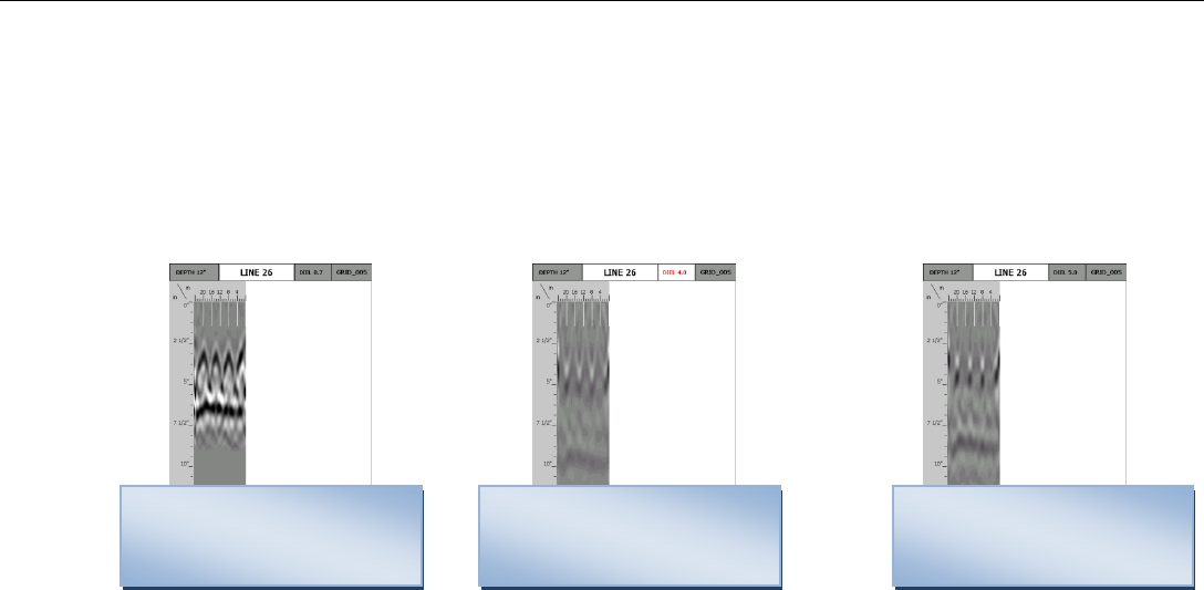
Note: When changing and setting the dielectric, the system will redisplay the data. The goal is to have “dots”
instead of hyperbolas’.
Dielectric Too High,
Hyperbola tails point down.
Adjust Dielectric Down
Dielectric Too Low,
Hyperbola tails point up . Dielectric about Right,
Displays Dots and no or
Adjust Dielectric Up very little tails.
Quick Start Guide StructureScan Mini HR
Geophysical Survey Systems, Inc. 39
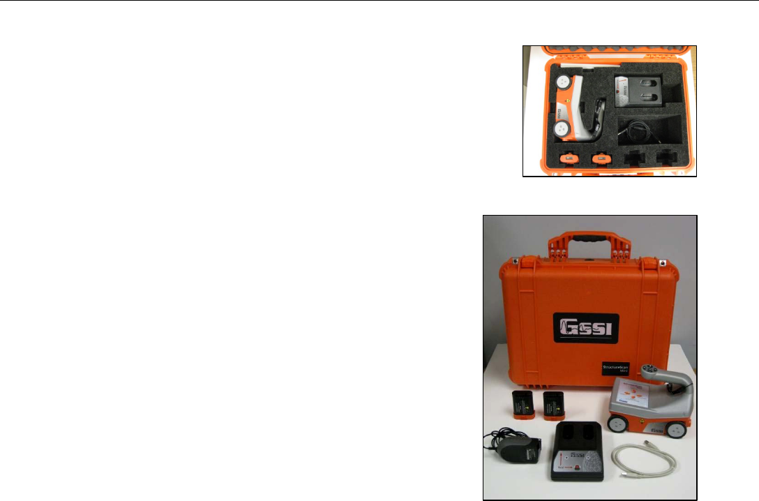
Appendix A: Inventory of Your System
• StructureScan Mini HR
• SD card (already inserted into the back of the Mini)
• Battery charger (2 slots)
• Battery charger adapter
• International plugs for the battery charger adapter (3)
• Quick Start Guide (this manual)
• USB cable
• Batteries (2)
• GSSI wrist strap
• Training DVD
• Resource CD
• Transit case
Note: If you wish to transfer any saved data to your PC, simply remove the SD
card and transfer the data to your PC.
Quick Start Guide StructureScan Mini HR
Geophysical Survey Systems, Inc. 40
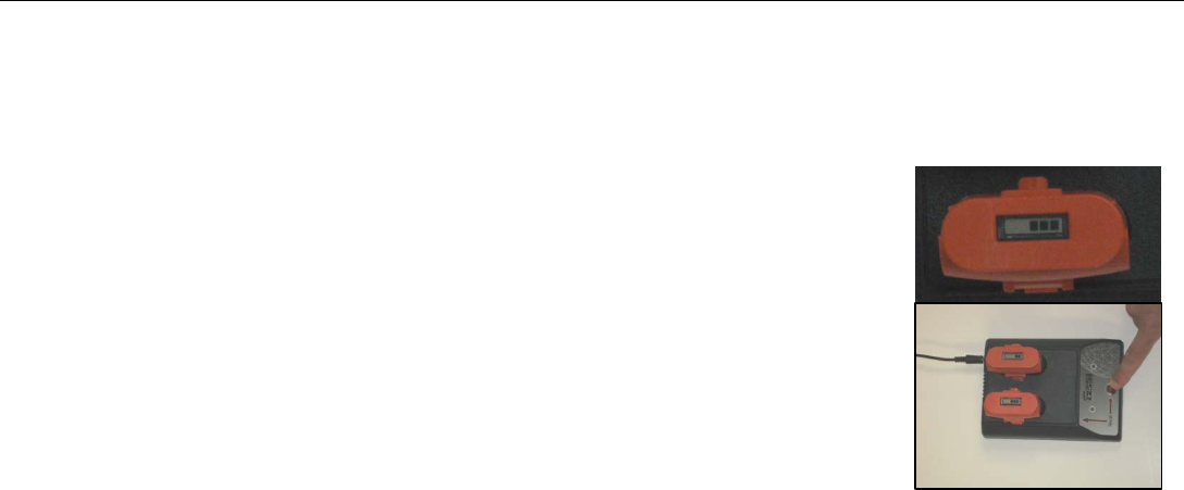
Appendix B: Battery/Charger Information
Your system comes with a two-slotted battery charger and adapter. It also comes with
three international interchangeable plugs.
• To charge your batteries, simply attach the adapter to the charger and plug in the
adapter. Insert one or both batteries. The batteries will charge one at a time. The bars
located at the top of the batteries will indicate how much charge is left in the battery.
• At times, you may wish to re-calibrate a battery. Simply insert a battery into the slot
on the left and press the RECAL button
• LED Lights – As the batteries are charging, the LED lights for each slot will do
different things.
• No Lights – No Batteries
• Green Flash – Fast Charging
• Green Solid – Fully Charged
• Yellow Flash – Recalibrating
• Yellow/Green – Recalibrated
• Yellow Solid – Standby
• Red Flash – Error
Quick Start Guide StructureScan Mini HR
Geophysical Survey Systems, Inc. 41
• If the charger remains plugged in and there are NO batteries in the charger, the charger will eventually begin to
“beep.” Since this can be annoying, it is recommend that you unplug the charger when not in use.
Appendix C: Sample Data
These examples are presented for informational use only. Conditions may be different at your site that may cause the
images to look different from the data shown here.
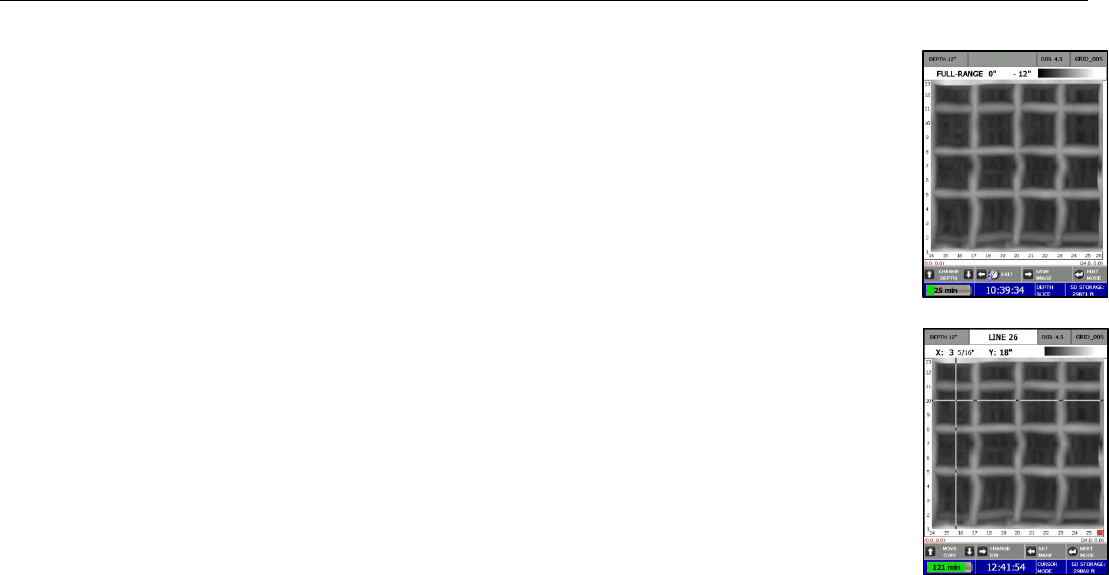
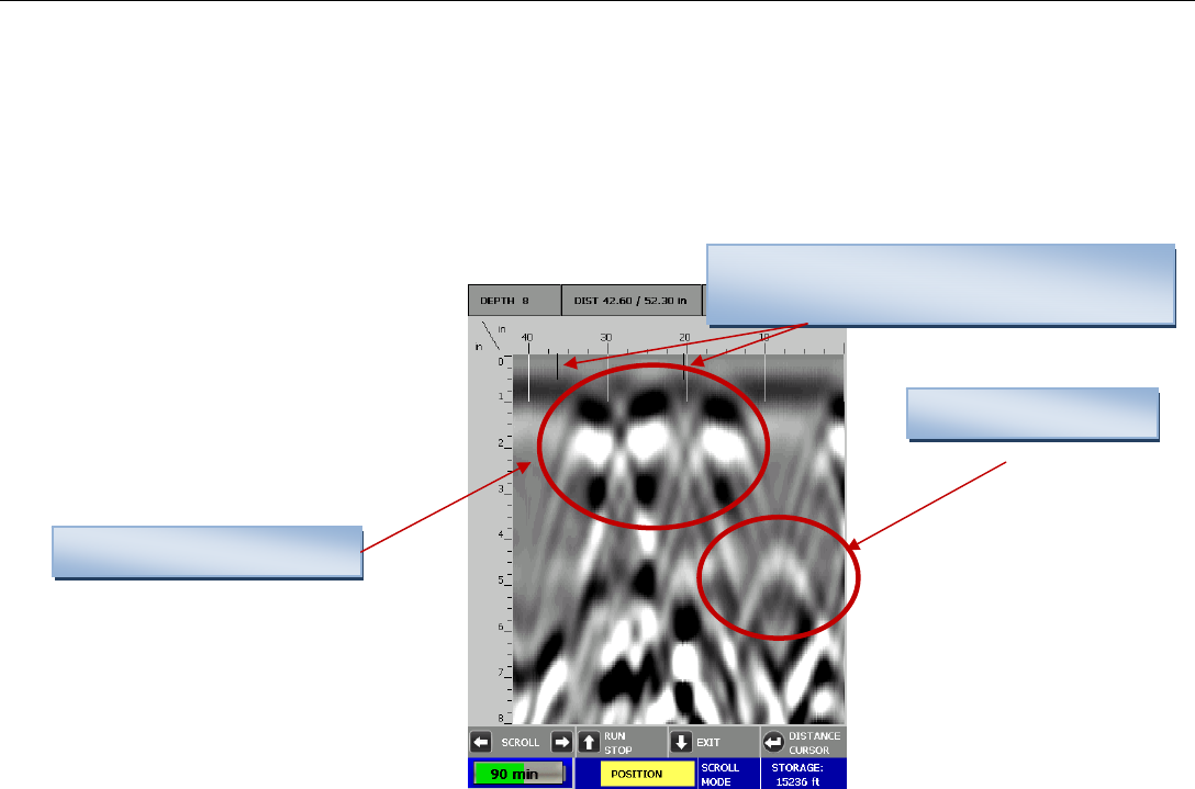
Example 1 – Concrete Block Data
Filled cell with rebar
Voids (2) within the
User Marks entered during collection to
identify the ends of each block (black lines)
Quick Start Guide StructureScan Mini HR
Geophysical Survey Systems, Inc. 42
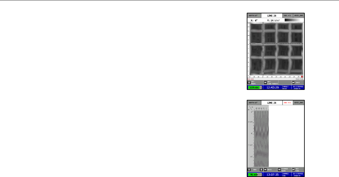
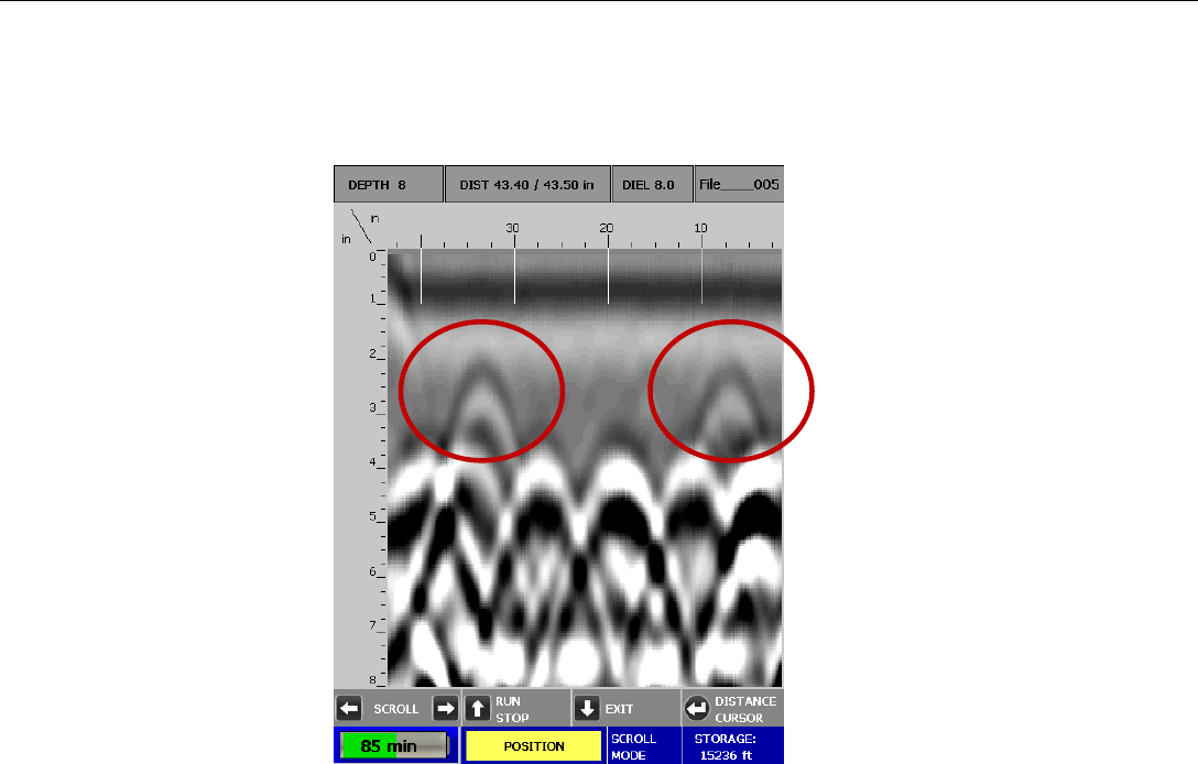
Example 2 – Rebar Data
This is an example of rebar. Note the distance between the peaks here (as well as at the location if you marked the area) is
approximately 8 inches. Also note the approximate depth, the brightness of the hyperbolas, and they tend to be at a
constant depth over short distances.
Quick Start Guide StructureScan Mini HR
Geophysical Survey Systems, Inc. 43
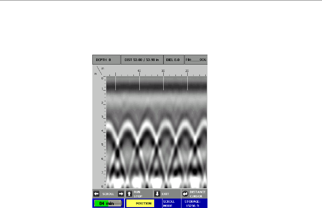
Example 3 – Mesh Data
This is an example of mesh. Note the distance between the peaks here (as well as at the location if you marked the area) is
approximately 6 inches. Note the approximate depth and the brightness of the hyperbolas. Wire mesh depths may be more
uneven than rebar.
Quick Start Guide StructureScan Mini HR
Geophysical Survey Systems, Inc. 44
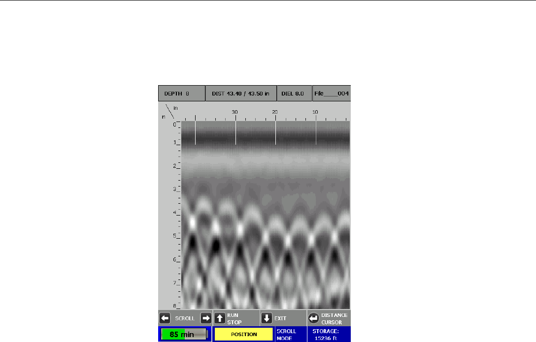
Example 4 – PVC
This is an example of two PVC pipes. Note that they tend to be dimmer than rebar.
Quick Start Guide StructureScan Mini HR
Geophysical Survey Systems, Inc. 45
Appendix D: Laser Information
Laser Information: General
• Do not intentionally point the laser into your eye. Do not look directly into the laser
light source.
• Do not place the laser in a position that may cause anyone to stare into the laser
beam intentionally or unintentionally.
• Always power down the unit when not in use.
• Never view a laser through an optical device such a binoculars or a
microscope.
Laser Information: Specific for the StructureScan Mini
HR
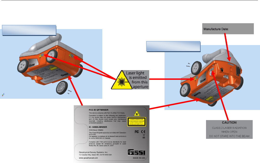
• Do not remove or deface any product labels.
• This product contains lasers used as guides. Do not stare into any of the beams.
• You may configure the lasers on or off. From the Main menu:
1 Select Ï Configure
2 Press Ï Ð and highlight Configuration and press Enter.
3 Press Ï Ð and highlight LASER

Quick Start Guide StructureScan Mini HR
Geophysical Survey Systems, Inc. 46
4 Press to toggle the laser On or Off.
• This product is designed to be opened by Field Service Professionals employed and/or trained by Geophysical
Survey Systems, Inc only. Do not open this product. Tampering with this product voids all warranties.
• The laser has no serviceable parts.
• The laser will flash several times during system boot up.
• The laser will blink (whether Laser is configured On or Off) when the battery life is low (10%)
• Remove the battery whenever transporting the product.
• Remove the battery whenever doing any self maintenance to the product, such as cleaning the windows of
the lasers.
• If the lasers are configured On and the lasers are not working during collection of data, do not open the product.
The product must be serviced by an authorized GSSI employee or representative only.
• If the lasers are configured On, they will work only while in the Collect Menu option.
• The lasers will remain on (if Laser is configured On) even if the unit goes into sleep mode.
Quick Start Guide StructureScan Mini HR
Geophysical Survey Systems, Inc. 47
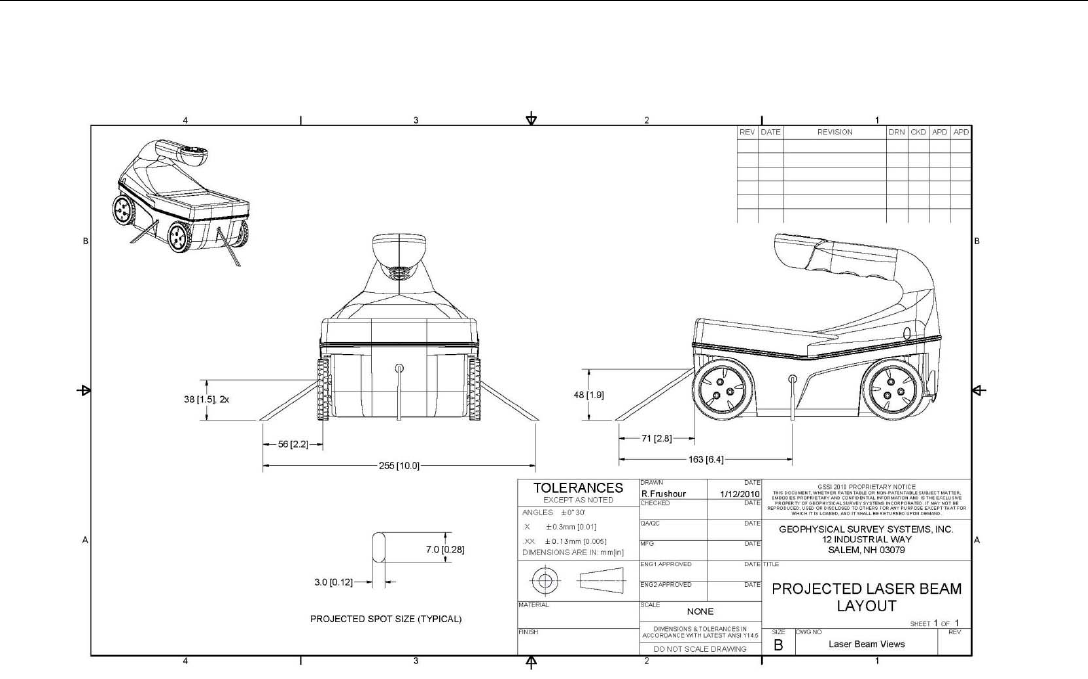
Laser Information: Projected Laser Beam Layout
Quick Start Guide StructureScan Mini HR
Geophysical Survey Systems, Inc. 48
Laser Information: Label Placement Diagrams
Front/Bottom View
Back/Bottom View